JP3801975B2 - Molding information display method and molding information management system for molding machine - Google Patents
Molding information display method and molding information management system for molding machine Download PDFInfo
- Publication number
- JP3801975B2 JP3801975B2 JP2002324362A JP2002324362A JP3801975B2 JP 3801975 B2 JP3801975 B2 JP 3801975B2 JP 2002324362 A JP2002324362 A JP 2002324362A JP 2002324362 A JP2002324362 A JP 2002324362A JP 3801975 B2 JP3801975 B2 JP 3801975B2
- Authority
- JP
- Japan
- Prior art keywords
- information
- molding machine
- display
- production
- control device
- Prior art date
- Legal status (The legal status is an assumption and is not a legal conclusion. Google has not performed a legal analysis and makes no representation as to the accuracy of the status listed.)
- Expired - Fee Related
Links
Images


Description
【0001】
【発明の属する技術分野】
本発明は、成形機の成形情報表示方法および成形情報管理システムに関し、特に、成形機の状態に関する成形情報を一目で確認可能な成形機の成形情報表示方法および成形情報管理システムに関するものである。
【0002】
【従来の技術】
従来から射出成形機において、成形の安定度を確認するためにショット毎のモニタデータをトレンドグラフとして表示させている。トレンドグラフは、射出成形機の表示部の他に、複数の射出成形機を監視・管理する上位コンピュータの表示部においても表示される。上位コンピュータの表示部では、監視している射出成形機についてのモニタデータの変動をトレンドグラフによって一目で確認することができる。モニタデータの表示には、ドットがプロットされて表示されるトレンドグラフの他に、数値で表示される数値表示がある。ここでモニタデータとは、成形サイクル毎に収集される成形特性を代表する成形機の動作モニタデータであり、加熱筒温度、射出充填時間、射出最前進位置、射出完了スクリュー位置、射出完了最前進圧力、成形品自体の特性(重量、寸法、画像など)等のことである。モニタ項目毎の測定データは、モニタデータとしてトレンドグラフまたはトレンド数値で表示される(例えば、特許文献1や特許文献2を参照)。
【0003】
【特許文献1】
特開平3−199025号公報(第2図)
【特許文献2】
特開2002−52590号公報(第2図)
【0004】
【発明が解決しようとする課題】
上記のトレンドグラフ表示やトレンド数値表示では全体の傾向を見るには、非常に良い表示ではあるが、生産切替えを行うと、表示するモニタデータが切替えの前後で異なってくるため、連続的に表示する場合には整合性のないものとなってしまう。また、生産切替えは、オペレータが成形機にて金型交換や材料交換作業を行うため、成形機から離れた場所にある上位コンピュータでは操作が困難である。
【0005】
本発明の目的は、上記の問題に鑑み、モニタデータに対してロット番号等の生産番号を付与し、上位コンピュータにて生産番号を用いた表示および生産切替時のデータ更新を可能にした成形機の成形情報表示方法および成形情報管理システムを提供することにある。
【0006】
【課題を解決するための手段および作用】
本発明に係る成形機の成形情報表示方法および成形情報管理システムは、上記目的を達成するために、次のように構成される。
【0007】
本発明に係る第1の成形機の成形情報表示方法(請求項1に対応)は、成形機またはこの成形機の運転を補助する周辺機器の状態を検出する各種検出器と、検出器から状態に係る情報を取り入れる制御装置および成形機を監視・管理する上位制御装置とを備え、上位制御装置の表示部が情報をショット毎にグラフまたは数値で表示する成形機システムにおいて、制御装置が情報に対してロット番号等の生産番号情報を付与し、上位制御装置が生産番号情報に基づいて生産切替えを判断し、情報を表示する画面の一部の表示内容をクリアすることを特徴とする。
【0008】
第1の成形情報表示方法によれば、上位制御装置の表示部において、情報に付与されたロット番号等の生産番号を取得し、この生産番号に基づいて生産切替えを判断し、情報を表示する画面の一部の表示内容をクリアするので、容易に上位制御装置において情報を表示する画面の一部の表示内容のクリアが行われる。
【0009】
本発明に係る第1の成形情報管理システム(請求項2に対応)は、成形機またはこの成形機の運転を補助する周辺機器の状態を検出する各種検出器と、検出器から状態に係る情報を取り入れる制御装置および成形機を監視・管理する上位制御装置とを備え、上位制御装置の表示部が情報をショット毎にグラフまたは数値で表示する成形機システムにおいて、制御装置が情報に対してロット番号等の生産番号情報を付与する生産番号情報付与部を備え、上位制御装置が生産番号情報に基づいて生産切替えを判断する生産切替判断部と、生産切替時に情報を表示する画面の一部の表示内容をクリアする情報更新表示部を備えることを特徴とする。
【0010】
第1の成形情報管理システムによれば、上位制御装置の表示部において、生産番号情報付与部によって付与されたロット番号等の生産番号情報に基づいて生産切替えを、生産切替判断部が判断し、情報更新表示部が情報を表示する画面の一部の表示内容をクリアするので、上位制御装置において容易に情報を表示する画面の一部の表示内容のクリアが行われる。
【0011】
【発明の実施の形態】
以下に、本発明の好適な実施形態を添付図面に従って説明する。
【0012】
なお、実施形態で説明される構成、形状、大きさおよび配置関係については本発明が理解・実施できる程度に概略的に示したものにすぎない。従って本発明は、以下に説明される実施形態に限定されるものではなく、特許請求の範囲に示される技術的思想の範囲を逸脱しない限り様々な形態に変更することができる。
【0013】
図1は、本発明が適用される成形機として射出成形機の例を示し、当該射出成形機に対して配備された周辺機器および制御システムを示す。101は射出成形機である。射出成形機101は、支持台102の上にベッド103を備え、ベッド103の上に射出装置104と型締め装置105が設けられている。射出成形機101の型締め装置105の近傍には成形品を撮像するディジタルカメラ(あるいはDVビデオカメラやビデオカメラ)121が設けられる。射出成形機101には射出成形の稼働を補助する周辺機器が配備される。周辺機器としては、金型温調機106、ドライヤ107、金型交換機108、材料混合機109などが配備されている。また、射出成形機101には、射出成形機の動作状態を検出する各種検出器が設けられている。射出成形機101には、例えば、加熱シリンダ113の温度を測る温度センサ131、スクリューの位置を検出するスクリュー位置検出部132、射出圧力を測る圧力センサ133等の検出器が設けられている。これらの検出器から、射出成形機101の動作状態に係る情報を得る。動作状態に係る情報からモニタデータとして、加熱筒温度、充填時間、射出最前進位置、可塑化時間、V−P切換圧力、充填ピーク圧、射出最前進圧力、サイクル時間等の情報を得る。さらに射出成形機101に対しては、監視・管理用の上位コンピュータ110が設けられている。なお、上位コンピュータ110は、射出成形機101以外の図示しない複数台の射出成形機も監視・管理をする。
【0014】
支持台102には、内部にマイクロコンピュータで構成されたプロセスコントローラ111が設けられる。支持台102の側部の外面には、タッチパネルで構成される操作・表示装置112が設けられている。操作・表示装置112に設けられた操作キーを操作することで成形作業に必要な指令を与えることができる。なお、ここで操作・表示装置112がタッチパネルであるとしたが、複数のキーボタンを備える表示部であってもよい。
【0015】
射出装置104は、プラスチック材料を可塑化する加熱シリンダ113と、加熱シリンダ113に供給されるプラスチック材料を貯蔵するホッパー114と、射出シリンダ115とから構成される。加熱シリンダ113の内部には、スクリュー113cが設けられている。ホッパー114から加熱シリンダ113の内部に供給されたプラスチック材料は、外周に巻かれたヒータ113bで加熱され、可塑化されながら計量が行われ、スクリュー113cの回転動作で先端側に送られ、スクリュー113cの前進で先端ノズル113aから射出される。射出シリンダ115では、駆動動力源として油圧駆動装置が用いられる。
【0016】
型締め装置105は、金型を備え、当該金型に加熱シリンダ113の先端ノズル113aから射出されたプラスチックが充填され、冷却して固化した後に、金型を開いて成形品を取出す装置である。型締め装置105では、水平に例えば4本のタイバー91が設けられている。タイバー91には、その先端に固定盤92が固定され、さらにタイバー91に沿って自在に動く可動盤93が取りつけられている。可動盤93は、型締めシリンダ117のピストンロッド94によって動かされる。固定盤92には固定型116aが設けられる。可動盤93には可動型116bが設けられる。固定型116aと可動型116bで金型116が形成される。型締め装置105は型締めシリンダ117を備える。型締めシリンダ117とピストンロッド94の作用で固定盤92に向かって可動盤93が移動し、固定型116aと可動型116bが合わせられると、金型116が形成される。固定型116aと可動型116bの対向する面に成形品を形作るための凹部が形成されている。加熱シリンダ113の先端ノズル113aから固定盤92を通して金型116の内部空間に対して可塑化されたプラスチック材料が充填される。加熱シリンダ113がプラスチック材料の射出を行うとき、金型116が開かないようにするために、型締めシリンダ117から強い型締め力が与えられる。
【0017】
上記の射出装置104と型締め装置105の各々の動作は、射出成形機101による連続して成形品を作る稼働状態において、一定の動作の順序関係を保ちながら繰返される。これらの動作の順序は、プロセスコントローラ111によるシーケンス制御によって与えられる。射出成形の工程は、主に、型締工程、射出工程(充填工程と保圧工程)、計量・冷却工程、型開き工程、突き出し工程から成る。各工程では型の開閉で3秒、射出工程(充填+保圧)で3秒、計量時間で6〜8秒(計量中に型では冷却を行う)、突き出し工程で1〜2秒がかかり、全行程で13〜16秒のサイクル時間で行われる。
【0018】
射出成形機101での射出装置104と型締め装置105の動作に基づく射出成形作業では、本体である射出成形機101の動作に関連して周辺機器である金型温調機106、ドライヤ107、金型交換機108、材料混合機109などが動作し、射出成形の生産作業を補助している。金型温調機106は金型116の温度を調整する機械であり、ドライヤ107は成形材料を乾燥する機械であり、金型交換機108は成形品に応じて金型116を交換する機械であり、材料混合機109は複数の材料を用いるときにこれを混合してホッパー114に供給する機械である。周辺機器としてはその他に取出しロボット、材料供給装置、搬送用コンベア、ランナ粉砕機、冷却装置等があるが、図1ではその図示が省略されている。以上の周辺機器の各々の動作は、破線122に示すごとく、射出成形機101のプロセスコントローラ111によって制御される場合もある。また周辺機器の各々の動作状態は、対応する検出器で検出され、動作状態に関する情報はプロセスコントローラ111に送給される。
【0019】
また、射出成形機101に設けられた温度センサ131、スクリュー位置検出部132、圧力センサ133等の検出器から、射出成形機101の動作状態に係る情報が、図示しない信号線を介してプロセスコントローラ111に送給される。
【0020】
上記射出成形機101に対して監視・管理用の上位コンピュータ110が設けられている。上位コンピュータ110は、通信ケーブル118によって射出成形機101のプロセスコントローラ111と接続されている。上位コンピュータ110は、射出成形機101の設置場所の近くに設けることもできるし、通信手段を経由して離れた場所に設けることもできる。離れた場所に置かれた上位コンピュータ110とプロセスコントローラ111を接続する場合には、各々は通信制御部および通信部を有し、通信回線として機能する通信ケーブル118を経由してデータ等のやり取りを行う。
【0021】
上位コンピュータ110は、プロセスコントローラ111を介して射出成形機101の動作状態に係るモニタデータを取得する。また、上位コンピュータ110はプロセスコントローラ111を介して射出成形機101および金型温調機106などの周辺機器の稼働状態を取得し、監視・管理する機能を有している。図1では、1台の射出成形機101のみが示されているが、実際には、同様な構成を有する複数台の射出成形機が設けらている。従って、上位コンピュータ110は、複数台の射出成形機の稼働を管理するように構成されている。
【0022】
次に図2に基づいてプロセスコントローラ111に関する構成を中心にして監視・管理・制御システムの全体構成を説明する。
【0023】
プロセスコントローラ111によって制御される対象は、射出成形機101の射出装置104および型締め装置105と、周辺機器201に含まれる金型温調機106、ドライヤ107、金型交換機108、材料混合機109などである。射出成形機101における射出装置104や型締め装置105では、これらの装置の駆動装置として含まれる油圧駆動装置の各種の弁機構あるいは各種の電動駆動装置も制御対象に含まれる。射出装置104、型締め装置105、金型温調機106、ドライヤ107、金型交換機108、材料混合機109の各々に対してプロセスコントローラ111の出力部から動作を指示する指令信号が出力される。射出装置104、型締め装置105、金型温調機106、ドライヤ107、金型交換機108、材料混合機109の各々には、各装置の動作状態を検出する検出器104a,105a,106a,107a,108a,109aが設けられている。図示例では、各装置の検出器は1つしか示されていないが、実際には、各種の状態量を検出することから各検出器はセンサ群によって構成されている。検出器104a〜109aから出力される検出信号は、プロセスコントローラ111の入力部204に入力される。
【0024】
また、プロセスコントローラ111は、射出成形機101の動作状態を各種検出器131,132,133から受信する。温度センサ131からは加熱シリンダ113の温度を受信する。加熱シリンダ113の温度にはノズル、加熱筒前部、加熱筒中部、加熱筒後部の温度があり、ここでは、ノズルの温度を検出している。温度センサ131はノズルの部分に位置しており、熱電対によって温度を感知する。スクリュー位置検出部132は、スクリュー113cの移動部材からスクリュー113cの位置を検出する。圧力センサ133は油圧回路を流れる油圧力を検出する。
【0025】
プロセスコントローラ111は、CPU203および入力部204と出力部202と記憶部206によって構成される。CPU203は、演算部205と制御部207とタイマ208を含む。演算部205は、記憶部206から制御プログラムや成形条件等の各種情報に関するデータを取り出して、射出成形機101の動作および周辺機器201の動作を制御し、射出成形による成形品の連続生産を実行し、射出成形機101による射出成形の稼働・運転を継続する。また記憶部206には、少なくとも、各種の動作のための制御プログラム206A、成形条件のデータ206B、成形品情報のデータ206C、射出成形機101の状態に関するデータ206D、稼働情報に関するデータ206E、操作・表示装置112の表示を制御する表示プログラム206Fが記憶されている。なお、表示プログラム206Fによって行われた処理結果が出力部202を介して、上位コンピュータ110に送信されるようにしてもよい。この場合、上位コンピュータ110は受信した処理結果に応じて表示部110aに、射出成形機101の操作・表示装置112と同じ画面を表示させる。上位コンピュータ110は表示部110aと生産切替判断部110bと情報更新表示部110cを備えており、プロセスコントローラ111から受けたデータに応じて、生産切替判断部110bおよび情報更新表示部110cの処理によって表示部110aに表示が行われる。
【0026】
制御プログラム206Aの中には、射出成形機101の動作制御、周辺機器201に含まれる各種機器の動作制御、生産計画に関する情報等が含まれる。成形機の状態に係るデータ206Dには、例えば、射出成形機101のI/O状態、ポンプ指令値、モータ指令値、モータ負荷トルクモニタ、検出器の電圧などのメンテナンス情報、エラー発生状況、生産数の状態が含まれる。成形品情報には、例えばショット毎のモニタデータや成形品画像データが含まれる。成形品画像データは、射出成形機101の型締め装置105の近傍に設けられたディジタルカメラ121による成形品の撮像で得られる。稼働情報のデータ206Eには、射出成形機101の稼働状態に関するデータと、周辺機器201の稼働状態に関するデータとが含まれる。
【0027】
なおプロセスコントローラ111が、遠隔地にある上位コンピュータ110と通信を行うようなシステムで構成される場合には、記憶部206の中に、上位コンピュータ110との間で通信を行うための通信用制御プログラムが設けられ、通信制御部が形成される。
【0028】
上記のプログラムやデータは、自在に書き込み・読み出しをすることができ、状況に応じて自在に変更することができる。また、この書き込み・読み出しおよび内容の変更は、遠隔の地にある外部からも自在に行うことができる。従って射出成形機101が設置された生産現場において制御プログラムやデータを変更することもできるし、あるいは遠隔の地からのリモート制御を行うこともできる。制御部207は、出力部202、入力部204、演算部205、記憶部206の各々の動作を制御し、プロセスコントローラ111の全体動作を管理する。
【0029】
上記のプロセスコントローラ111によれば、主に、射出成形機101において所定の手順で成形品を繰返して生産するためのシーケンス制御、射出成形機101等の各部の動作状態に関するプロセス制御、成形品の良否に関する間接的な良否判断制御等が実行される。
【0030】
上記の構成を有するプロセスコントローラ111に対して、前述のごとく、操作・表示装置112と上位コンピュータ110とが接続されている。操作・表示装置112は、図1で説明した通り、射出成形機101の支持台102に付設されている。上位コンピュータ110は、射出成形機101のプロセスコントローラ111に対して生産計画や稼働・運転の手順を指定する制御プログラムや成形条件の設定・変更を指定するためのデータの提供や、プロセスコントローラ111から受信したモニタデータを確認するための管理用の装置である。検出器104a〜109aおよび温度センサ131、スクリュー位置検出部132、圧力センサ133によってプロセスコントローラ111に与えられ、かつプロセスコントローラ111の記憶部206に記憶された射出成形機101の動作状態および周辺機器201の各々の動作状態に関する情報は、上位コンピュータ110に与えられる。
【0031】
射出成形情報は、成形機情報、生産情報、成形条件管理情報、品質管理情報、製品情報、周辺機器情報から成る。成形機情報としては、成形機の状態やメンテナンスデータ等である。生産情報としては、現在生産中の製品、予定生産数、実際の生産数、エラー発生数、稼働時間、終了予定時刻等である。成形条件管理情報としては、現在成形中の成形条件の参照などである。品質管理情報は、モニタデータショット毎の成形品画像等がある。周辺機器情報としては、接続された周辺機器の状態や設定情報である。
【0032】
図3は表示プログラム206Fで行われる処理の概念ブロック構成図である。表示プログラム206Fは、モニタデータ取得部301、最大値・最小値取得部302、平均値算出部303、標準偏差算出部304、グラフ表示部305、数値表示部306、ロット番号付与部307とから構成される。これらは、表示を行うためにCPUで処理されるプログラムであり、記憶部206に格納されたものである。ここで、表示プログラム206Fの中に格納されているように記載されているが、表示プログラム206F外に格納されていてもよい。
【0033】
モニタデータ取得部301は、温度センサ131、スクリュー位置検出部132、圧力センサ133からのデータを取得する。温度センサ131から取得した温度データは、加熱筒温度データとなる。スクリュー位置検出部132から取得した位置データは、射出最前進位置データとなる。圧力センサ133から取得した圧力データは、スクリュー位置検出部132から取得した位置データを用いて、充填ピーク圧データと射出最前進圧力データとなる。充填時間データ、可塑化時間データ、サイクル時間データは位置データを用いて、タイマ208によって計られる。V−P切換圧力データは、位置データ、圧力データおよびタイマから検出される。
【0034】
ここで、加熱筒温度とは、加熱筒のノズルの部分の温度である。充填時間とは、射出速度が止まる(キャビティが満たされる)までの時間であり、射出工程の開始信号と同時に、タイマ208でカウントし、見かけ上の速度がなくなるまでの時間を計ることによって取得する。なお、射出工程は充填工程と保圧工程とから成り、それぞれの工程の時間の和(充填時間+保圧時間)が射出時間となっている。射出最前進位置とは、射出工程中のスクリュー113cが到達した最前進の位置であり、スクリュー113cの移動部材等から検出される。可塑化時間とは、計量工程の時間であり、計量工程の開始のタイミングから、計量完了位置までの時間をタイマ208で計ることによって取得する。なお、計量完了位置はスクリュー位置検出部132から検出する。V−P切換圧力とは、充填工程(射出速度V)と保圧工程(保圧力P)との切り換え地点での圧力である。充填ピーク圧とは、充填工程における最大射出圧力である。射出最前進圧力とは、射出最前進位置に達したときの圧力である。サイクル時間とは、型締工程開始から、次の型締工程開始までの時間である。なお、射出成形は型締工程、ノズル前進工程、射出工程、計量・冷却工程、ノズル後進工程、型開き工程、突き出し工程、中間時間工程から成る。
【0035】
最大値・最小値取得部302は、上記した加熱筒温度、充填時間、射出最前進位置、可塑化時間、V−P切換圧力、充填ピーク圧、射出最前進圧力、サイクル時間の最大値と最小値を取得する。平均値算出部303および標準偏差算出部304は、加熱筒温度、充填時間、射出最前進位置、可塑化時間、V−P切換圧力、充填ピーク圧、射出最前進圧力、サイクル時間のそれぞれのモニタデータの平均値および標準偏差を算出する。
【0036】
グラフ表示部305は、モニタデータに応じてプロットを行い、操作・表示装置112にグラフを表示する。数値表示部306は、取得したモニタデータに応じて数値でそれぞれのモニタデータを表示する。ロット番号付与部307は、モニタデータ取得部301で取得されたデータおよび算出されたデータにロット番号を付与する。これによりデータにはロット番号が付与され、後述するように、上位コンピュータ110の表示部110aにおいて表示される際に、生産切替判断部110bによってロット番号が参照され、生産切替が判断され、さらに、生産切替と判断されると、情報更新表示部110cによって情報の更新が行われる。
【0037】
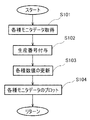
次に動作フロー図と表示画面を示す図に従って、表示プログラム206Fと上位コンピュータ110の生産切替判断部110bおよび情報更新表示部110cにおいて行われる処理を説明する。図4は表示プログラム206Fにおいて行われる処理の一部を説明する動作フロー図である。モニタデータ取得部301によって各種モニタデータが取得される(ステップS101)。取得された各種モニタデータに対してロット番号を付与する(ステップS102)。取得されたモニタデータに基づいて、最大値・最小値取得部302、平均値算出部303、標準偏差算出部304が動作し、各種数値が更新される(ステップS103)。グラフ表示部305によって各種モニタデータがプロットされ、グラフ表示される(ステップS104)。上記ステップは各種モニタデータが取得される毎に行われる。なお、グラフ表示でない場合には、数値表示部306によって数値表示の数値が更新されていく。
【0038】
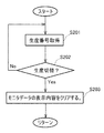
図5は、上位コンピュータ110の生産切替判断部110bおよび情報更新表示部110cにおいて行われる処理を説明する動作フロー図である。生産切替判断部110bが、射出成形機101のプロセスコントローラ111からロット番号を取得する(ステップS201)。生産切替判断部110bが取得したロット番号から生産切替が行われたか否かを判断する(ステップS202)。生産切替が行われたと判断すると、情報更新表示部110cがモニタデータの表示内容をクリアし、情報の更新を行う(ステップS203)。
【0039】
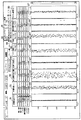
次に、上位コンピュータ110の表示部110aに表示される画面を示す図を参照して、上記動作を説明する。図6は、生産切替がない場合のモニタデータをトレンドグラフ表示したときの画面を示す図である。表示された画面には、モニタデータ取得部301で取得された加熱筒温度10、充填時間20、射出最前進位置30、可塑化時間40、V−P切換圧力50、充填ピーク圧60、射出最前進圧力70、サイクル時間80が表示されている。上記データの最大値、最小値、平均値、標準偏差、レンジ(R)、6CV(%)がそれぞれ、符号11〜16、符号21〜26、符号31〜36、符号41〜46、符号51〜56、符号61〜66、符号71〜76、符号81〜86に表示される。これらは上述した最大値・最小値取得部302、平均値算出部303、標準偏差算出部304によって取得、算出された数値である。グラフ表示部305によって、上記データのそれぞれのプロットがなされ、モニタデータ表示部17,27,37,47,57,67,77,87にグラフ表示される。
【0040】
符号90はトレンドグラフ表示をする際に押すボタンまたはアイコンであり、符号91はトレンド数値表示をする際に押すボタンまたはアイコンである。以下、トレンドグラフ表示アイコン90、トレンド数値表示アイコン91という。符号92はロット番号である。ここで、生産切替がない場合のモニタデータをトレンドグラフ表示したときの画面ではロット番号92が「TEST0001」となっている。
【0041】
図7は、生産切替があった後のモニタデータをトレンドグラフ表示したときの画面を示す図である。この図では生産切替があった後に、40ショット行われたときのモニタデータをトレンドグラフ表示したものである。生産切替判断部110bが取得したロット番号から生産切替が行われたろ判断すると、情報更新表示部110cがモニタデータの表示内容をクリアし、情報の更新を行う。このため、図で示したようにモニタデータの表示内容がクリアされ、新たな生産が行われていることがわかる。ここで、生産切替があった後のモニタデータをトレンドグラフ表示したときの画面ではロット番号92が「TEST0002」となっており、生産切替があったことがわかる。
【0042】
以上のように上位制御装置において、生産切替を判断し、モニタデータの表示内容をクリアするので、生産切替が容易にわかる。これによって、生産切替を伴った射出成形機の稼働状況を正確に連続表示し、連続監視が可能となる。なお、実施形態の説明ではトレンドグラフ表示を例にして説明したが、トレンド数値表示であっても同様に、生産切替時にモニタデータの表示内容がクリアされる。
【0043】
【発明の効果】
以上の説明で明らかなように本発明によれば、次の効果を奏する。
【0044】
本発明に係る成形機の成形情報表示方法および成形情報管理システムによれば、射出成形機の制御装置が検出された射出成形機の状態に係る情報に対してロット番号を付与するロット番号付与部を備え、上位制御装置がロット番号に基づいて生産切替を判断する生産切替判断部と生産切替時に表示内容をクリアする情報更新表示部を備えるので、上位制御装置において容易に生産切替が確認できる。
【図面の簡単な説明】
【図1】本発明が適用される射出成形機と周辺機器と制御システムを示すシステム構成図である。
【図2】プロセスコントローラを中心として制御系の詳細な構成を示すブロック図である。
【図3】表示プログラムで行われる処理の概念ブロック構成図である。
【図4】表示プログラムにおいて行われる処理の一部を説明する動作フロー図である。
【図5】上位コンピュータの生産切替判断部および情報更新表示部において行われる処理を説明する動作フロー図である。
【図6】生産切替がない場合のモニタデータをトレンドグラフ表示したときの画面を示す図である。
【図7】生産切替があった後のモニタデータをトレンドグラフ表示したときの画面を示す図である。
【符号の説明】
101 射出成形機
104 射出装置
104a〜109a 検出器
110 上位コンピュータ
110a 表示部
110b 生産切替判断部
110c 情報更新表示部
111 プロセスコントローラ
112 操作・表示装置
113 加熱シリンダ
113a 先端ノズル
113b ヒータ
113c スクリュー
115 射出シリンダ
131 温度センサ
132 スクリュー位置検出部
133 圧力センサ
301 モニタデータ取得部
302 最大・最小値取得部
303 平均値算出部
304 標準偏差算出部
305 グラフ表示部
306 数値表示部
307 ロット番号付与部[0001]
BACKGROUND OF THE INVENTION
The present invention relates to a molding information display method and a molding information management system for a molding machine, and more particularly to a molding information display method and a molding information management system for a molding machine that can confirm molding information related to the state of the molding machine at a glance.
[0002]
[Prior art]
Conventionally, in an injection molding machine, monitor data for each shot is displayed as a trend graph in order to confirm the stability of molding. The trend graph is displayed not only on the display unit of the injection molding machine but also on the display unit of a host computer that monitors and manages a plurality of injection molding machines. On the display unit of the host computer, changes in monitor data for the monitored injection molding machine can be confirmed at a glance with a trend graph. In addition to the trend graph in which dots are plotted, the monitor data is displayed in numerical values. Here, the monitor data is the operation monitor data of the molding machine representative of the molding characteristics collected for each molding cycle, and the heating cylinder temperature, injection filling time, injection most advanced position, injection completion screw position, and injection completion most advanced Pressure, characteristics of the molded product itself (weight, dimensions, images, etc.). Measurement data for each monitor item is displayed as a trend data or a trend value as monitor data (see, for example, Patent Document 1 and Patent Document 2).
[0003]
[Patent Document 1]
Japanese Patent Laid-Open No. 3-199025 (FIG. 2)
[Patent Document 2]
Japanese Patent Laid-Open No. 2002-52590 (FIG. 2)
[0004]
[Problems to be solved by the invention]
In the above trend graph display and trend numerical display, it is a very good display to see the overall trend, but when you switch production, the monitor data to be displayed will be different before and after switching, so it will be displayed continuously If you do, it will be inconsistent. In addition, since the operator performs mold exchange and material exchange work on the molding machine, it is difficult to operate on a host computer located away from the molding machine.
[0005]
In view of the above problems, an object of the present invention is to provide a production number such as a lot number to monitor data, and display using the production number in a host computer and update of data at the time of production switching. The present invention provides a molding information display method and a molding information management system.
[0006]
[Means and Actions for Solving the Problems]
In order to achieve the above object, a molding information display method and a molding information management system for a molding machine according to the present invention are configured as follows.
[0007]
A molding information display method for a first molding machine according to the present invention (corresponding to claim 1) includes various detectors that detect the status of the molding machine or peripheral devices that assist the operation of the molding machine, and the state from the detector. In a molding machine system that includes a control device that incorporates information related to the above and a higher-level control device that monitors and manages the molding machine, the display unit of the higher-level control device displays information in a graph or numerical value for each shot. Production number information such as a lot number is assigned to the host control device, and the host control device determines production switching based on the production number information, and clears a part of the display contents of the information display screen .
[0008]
According to the first molding information display method, a production number such as a lot number assigned to the information is acquired in the display unit of the host controller, production switching is determined based on the production number, and information is displayed. Since the display content of a part of the screen is cleared , the display content of a part of the screen for displaying information is easily cleared in the host control device.
[0009]
A first molding information management system according to the present invention (corresponding to claim 2) includes various detectors that detect the state of a molding machine or peripheral devices that assist the operation of the molding machine, and information on the state from the detector. In a molding machine system in which a display unit of the host control device displays information in a graph or numerical value for each shot, A production number information assigning unit for assigning production number information such as a number, and a higher-level control device that determines production switching based on the production number information, and a part of a screen that displays information at the time of production switching An information update display unit for clearing the display content is provided.
[0010]
According to the first molding information management system, the production switching judgment unit judges the production switching based on the production number information such as the lot number given by the production number information giving unit in the display unit of the host controller. Since the information update display unit clears part of the display content of the screen displaying information, the host control device easily clears part of the display content of the screen displaying information.
[0011]
DETAILED DESCRIPTION OF THE INVENTION
Preferred embodiments of the present invention will be described below with reference to the accompanying drawings.
[0012]
It should be noted that the configuration, shape, size, and arrangement relationship described in the embodiments are merely schematically shown to the extent that the present invention can be understood and implemented. Therefore, the present invention is not limited to the embodiments described below, and can be modified in various forms without departing from the scope of the technical idea shown in the claims.
[0013]
FIG. 1 shows an example of an injection molding machine as a molding machine to which the present invention is applied, and shows peripheral devices and a control system provided for the injection molding machine. 101 is an injection molding machine. The
[0014]
The
[0015]
The
[0016]
The
[0017]
The operations of the
[0018]
In the injection molding work based on the operations of the
[0019]
In addition, information relating to the operation state of the
[0020]
A
[0021]
The
[0022]
Next, the overall configuration of the monitoring / management / control system will be described with reference to FIG.
[0023]
The objects controlled by the
[0024]
Further, the
[0025]
The
[0026]
The
[0027]
If the
[0028]
The above programs and data can be freely written and read, and can be freely changed according to the situation. In addition, this writing / reading and content change can be freely performed from the outside in a remote place. Therefore, the control program and data can be changed at the production site where the
[0029]
According to the above-described
[0030]
As described above, the operation /
[0031]
The injection molding information includes molding machine information, production information, molding condition management information, quality management information, product information, and peripheral device information. The molding machine information includes the state of the molding machine and maintenance data. The production information includes a product currently being produced, a planned production number, an actual production number, an error occurrence number, an operation time, a scheduled end time, and the like. The molding condition management information includes reference to molding conditions currently being molded. The quality control information includes a molded product image for each monitor data shot. Peripheral device information includes the status and setting information of the connected peripheral device.
[0032]
FIG. 3 is a conceptual block diagram of processing performed by the
[0033]
The monitor
[0034]
Here, the heating cylinder temperature is the temperature of the nozzle portion of the heating cylinder. The filling time is the time until the injection speed stops (the cavity is filled), and is obtained by counting with the
[0035]
The maximum value / minimum
[0036]
The
[0037]
Next, processing performed in the
[0038]
FIG. 5 is an operation flowchart for explaining processing performed in the production
[0039]
Next, the operation will be described with reference to a diagram showing a screen displayed on the
[0040]
[0041]
FIG. 7 is a diagram showing a screen when the monitor data after the production switching is displayed in a trend graph. In this figure, monitor data when 40 shots are performed after production switching is displayed in a trend graph. When the production
[0042]
As described above, since the host controller determines the production switching and clears the display contents of the monitor data, the production switching can be easily understood. As a result, the operation status of the injection molding machine with production switching can be continuously displayed accurately and continuously monitored. In the description of the embodiment, the trend graph display has been described as an example, but the display contents of the monitor data are cleared at the time of production switching in the same manner even in the case of the trend numerical value display.
[0043]
【The invention's effect】
As is apparent from the above description, the present invention has the following effects.
[0044]
According to the molding information display method and molding information management system of a molding machine according to the present invention, a lot number assigning unit that assigns a lot number to information related to the state of the injection molding machine detected by the control device of the injection molding machine And the host control device includes a production switching determination unit that determines the production switching based on the lot number and an information update display unit that clears the display contents at the time of the production switching, so that the production switching can be easily confirmed in the host control device.
[Brief description of the drawings]
FIG. 1 is a system configuration diagram showing an injection molding machine, peripheral devices, and a control system to which the present invention is applied.
FIG. 2 is a block diagram showing a detailed configuration of a control system centering on a process controller.
FIG. 3 is a conceptual block configuration diagram of processing performed by a display program.
FIG. 4 is an operation flowchart for explaining a part of processing performed in a display program.
FIG. 5 is an operation flow diagram illustrating processing performed in a production switching determination unit and an information update display unit of a host computer.
FIG. 6 is a diagram showing a screen when monitor data is displayed in a trend graph when there is no production switching.
FIG. 7 is a diagram showing a screen when monitor data after production switching is displayed in a trend graph.
[Explanation of symbols]
DESCRIPTION OF
Claims (2)
前記制御装置は前記情報に対して生産番号情報を付与し、
前記上位制御装置は前記生産番号情報に基づいて生産切替えを判断し、前記情報を表示する画面の一部の表示内容をクリアすることを特徴とする成形機の成形情報表示方法。Various detectors that detect the state of a molding machine or peripheral equipment that assists the operation of the molding machine, a control device that takes in state information from the detector, and a host control device that monitors and manages the molding machine In the molding machine system in which the display unit of the host controller displays the information in a graph or numerical value for each shot,
The control device gives production number information to the information,
The molding information display method for a molding machine, wherein the host control device determines production switching based on the production number information, and clears a display content of a part of a screen displaying the information.
前記制御装置は前記情報に対して生産番号情報を付与する生産番号情報付与手段を備え、
前記上位制御装置は前記生産番号情報に基づいて生産切替えを判断する生産切替判断手段と、生産切替時に前記情報を表示する画面の一部の表示内容をクリアする情報更新表示手段を備えることを特徴とする成形情報管理システム。Various detectors that detect the state of a molding machine or peripheral equipment that assists the operation of the molding machine, a control device that takes in state information from the detector, and a host control device that monitors and manages the molding machine In the molding machine system in which the display unit of the host controller displays the information in a graph or numerical value for each shot,
The control device comprises production number information giving means for giving production number information to the information,
The host control device includes production switching judgment means for judging production switching based on the production number information, and information update display means for clearing a part of display contents of a screen for displaying the information at the time of production switching. Molding information management system.
Priority Applications (1)
| Application Number | Priority Date | Filing Date | Title |
|---|---|---|---|
| JP2002324362A JP3801975B2 (en) | 2002-11-07 | 2002-11-07 | Molding information display method and molding information management system for molding machine |
Applications Claiming Priority (1)
| Application Number | Priority Date | Filing Date | Title |
|---|---|---|---|
| JP2002324362A JP3801975B2 (en) | 2002-11-07 | 2002-11-07 | Molding information display method and molding information management system for molding machine |
Publications (3)
| Publication Number | Publication Date |
|---|---|
| JP2004155126A JP2004155126A (en) | 2004-06-03 |
| JP2004155126A5 JP2004155126A5 (en) | 2005-05-19 |
| JP3801975B2 true JP3801975B2 (en) | 2006-07-26 |
Family
ID=32803975
Family Applications (1)
| Application Number | Title | Priority Date | Filing Date |
|---|---|---|---|
| JP2002324362A Expired - Fee Related JP3801975B2 (en) | 2002-11-07 | 2002-11-07 | Molding information display method and molding information management system for molding machine |
Country Status (1)
| Country | Link |
|---|---|
| JP (1) | JP3801975B2 (en) |
Families Citing this family (3)
| Publication number | Priority date | Publication date | Assignee | Title |
|---|---|---|---|---|
| JP2014215636A (en) * | 2013-04-22 | 2014-11-17 | 株式会社松井製作所 | Smart operation system for plastic molding process line |
| JP2014215635A (en) * | 2013-04-22 | 2014-11-17 | 株式会社松井製作所 | Smart operation method and system for plastic molding process line |
| JP2022077204A (en) * | 2020-11-11 | 2022-05-23 | セイコーエプソン株式会社 | Injection molding machine management system |
-
2002
- 2002-11-07 JP JP2002324362A patent/JP3801975B2/en not_active Expired - Fee Related
Also Published As
| Publication number | Publication date |
|---|---|
| JP2004155126A (en) | 2004-06-03 |
Similar Documents
| Publication | Publication Date | Title |
|---|---|---|
| JP5558039B2 (en) | Molding condition setting device, molding condition setting method and molding condition setting screen | |
| JP3801975B2 (en) | Molding information display method and molding information management system for molding machine | |
| JP2021062504A (en) | Injection molder management support apparatus and injection molder | |
| JP3905020B2 (en) | Molding information display method and molding information management system for molding machine | |
| JP5289528B2 (en) | Nozzle touch control device for injection molding machine | |
| JP3895666B2 (en) | Molding information display method and molding information management system for molding machine | |
| JP2545465B2 (en) | Method for automatically setting upper and lower limits of molding conditions of molding machine | |
| JP3776869B2 (en) | Molding information display method and molding information management system for molding machine | |
| JP3872417B2 (en) | Molding information display method and molding information management system for molding machine | |
| CN113646109A (en) | Preview display function of operation of injection molding machine | |
| JP3872416B2 (en) | Molding information display method and molding information management system for molding machine | |
| JP3747025B2 (en) | Molding information display method and molding information management system for molding machine | |
| JP3872415B2 (en) | Molding information display method and molding information management system for molding machine | |
| JP5653599B2 (en) | Molding condition setting screen, molding condition setting device, and molding condition setting method | |
| JP7331081B2 (en) | Injection molding machine, display method for injection molding machine, and display method for display device of injection molding machine | |
| JP2004142204A (en) | Injection-molding machine and method for measuring resin viscosity in injection-molding machine | |
| JP3795005B2 (en) | Injection molding machine, injection molding method and control device for injection molding machine | |
| JP5702319B2 (en) | Production machine display method and apparatus | |
| JPH03270916A (en) | Control panel for molding machine | |
| JP4263661B2 (en) | Monitoring display method of molding machine | |
| JP3467360B2 (en) | Injection molding machine | |
| JPH02128822A (en) | Method and apparatus for setting optimum monitor tolerant value of injection molding machine | |
| CN113001919A (en) | Injection molding machine, control method thereof, and recording medium storing control program | |
| CN113272111A (en) | Injection molding machine system and controller for industrial machine | |
| JPH04282219A (en) | Monitoring device for metering time in injection molding machine |
Legal Events
| Date | Code | Title | Description |
|---|---|---|---|
| A521 | Request for written amendment filed |
Free format text: JAPANESE INTERMEDIATE CODE: A523 Effective date: 20040708 |
|
| A621 | Written request for application examination |
Free format text: JAPANESE INTERMEDIATE CODE: A621 Effective date: 20040708 |
|
| A977 | Report on retrieval |
Free format text: JAPANESE INTERMEDIATE CODE: A971007 Effective date: 20060110 |
|
| A131 | Notification of reasons for refusal |
Free format text: JAPANESE INTERMEDIATE CODE: A131 Effective date: 20060131 |
|
| A521 | Request for written amendment filed |
Free format text: JAPANESE INTERMEDIATE CODE: A523 Effective date: 20060329 |
|
| TRDD | Decision of grant or rejection written | ||
| A01 | Written decision to grant a patent or to grant a registration (utility model) |
Free format text: JAPANESE INTERMEDIATE CODE: A01 Effective date: 20060425 |
|
| A61 | First payment of annual fees (during grant procedure) |
Free format text: JAPANESE INTERMEDIATE CODE: A61 Effective date: 20060426 |
|
| R150 | Certificate of patent or registration of utility model |
Free format text: JAPANESE INTERMEDIATE CODE: R150 Ref document number: 3801975 Country of ref document: JP Free format text: JAPANESE INTERMEDIATE CODE: R150 |
|
| FPAY | Renewal fee payment (event date is renewal date of database) |
Free format text: PAYMENT UNTIL: 20090512 Year of fee payment: 3 |
|
| FPAY | Renewal fee payment (event date is renewal date of database) |
Free format text: PAYMENT UNTIL: 20120512 Year of fee payment: 6 |
|
| R250 | Receipt of annual fees |
Free format text: JAPANESE INTERMEDIATE CODE: R250 |
|
| FPAY | Renewal fee payment (event date is renewal date of database) |
Free format text: PAYMENT UNTIL: 20150512 Year of fee payment: 9 |
|
| R250 | Receipt of annual fees |
Free format text: JAPANESE INTERMEDIATE CODE: R250 |
|
| R250 | Receipt of annual fees |
Free format text: JAPANESE INTERMEDIATE CODE: R250 |
|
| R250 | Receipt of annual fees |
Free format text: JAPANESE INTERMEDIATE CODE: R250 |
|
| R250 | Receipt of annual fees |
Free format text: JAPANESE INTERMEDIATE CODE: R250 |
|
| R250 | Receipt of annual fees |
Free format text: JAPANESE INTERMEDIATE CODE: R250 |
|
| LAPS | Cancellation because of no payment of annual fees |