JP3801889B2 - Terminal fitting - Google Patents
Terminal fitting Download PDFInfo
- Publication number
- JP3801889B2 JP3801889B2 JP2001272453A JP2001272453A JP3801889B2 JP 3801889 B2 JP3801889 B2 JP 3801889B2 JP 2001272453 A JP2001272453 A JP 2001272453A JP 2001272453 A JP2001272453 A JP 2001272453A JP 3801889 B2 JP3801889 B2 JP 3801889B2
- Authority
- JP
- Japan
- Prior art keywords
- recess
- edge
- locked
- terminal fitting
- plates
- Prior art date
- Legal status (The legal status is an assumption and is not a legal conclusion. Google has not performed a legal analysis and makes no representation as to the accuracy of the status listed.)
- Expired - Lifetime
Links
Images


Classifications
-
- H—ELECTRICITY
- H01—ELECTRIC ELEMENTS
- H01R—ELECTRICALLY-CONDUCTIVE CONNECTIONS; STRUCTURAL ASSOCIATIONS OF A PLURALITY OF MUTUALLY-INSULATED ELECTRICAL CONNECTING ELEMENTS; COUPLING DEVICES; CURRENT COLLECTORS
- H01R13/00—Details of coupling devices of the kinds covered by groups H01R12/70 or H01R24/00 - H01R33/00
- H01R13/02—Contact members
- H01R13/10—Sockets for co-operation with pins or blades
- H01R13/11—Resilient sockets
- H01R13/113—Resilient sockets co-operating with pins or blades having a rectangular transverse section
-
- H—ELECTRICITY
- H01—ELECTRIC ELEMENTS
- H01R—ELECTRICALLY-CONDUCTIVE CONNECTIONS; STRUCTURAL ASSOCIATIONS OF A PLURALITY OF MUTUALLY-INSULATED ELECTRICAL CONNECTING ELEMENTS; COUPLING DEVICES; CURRENT COLLECTORS
- H01R43/00—Apparatus or processes specially adapted for manufacturing, assembling, maintaining, or repairing of line connectors or current collectors or for joining electric conductors
- H01R43/16—Apparatus or processes specially adapted for manufacturing, assembling, maintaining, or repairing of line connectors or current collectors or for joining electric conductors for manufacturing contact members, e.g. by punching and by bending
-
- H—ELECTRICITY
- H01—ELECTRIC ELEMENTS
- H01R—ELECTRICALLY-CONDUCTIVE CONNECTIONS; STRUCTURAL ASSOCIATIONS OF A PLURALITY OF MUTUALLY-INSULATED ELECTRICAL CONNECTING ELEMENTS; COUPLING DEVICES; CURRENT COLLECTORS
- H01R13/00—Details of coupling devices of the kinds covered by groups H01R12/70 or H01R24/00 - H01R33/00
- H01R13/02—Contact members
- H01R13/10—Sockets for co-operation with pins or blades
- H01R13/11—Resilient sockets
- H01R13/111—Resilient sockets co-operating with pins having a circular transverse section
-
- H—ELECTRICITY
- H01—ELECTRIC ELEMENTS
- H01R—ELECTRICALLY-CONDUCTIVE CONNECTIONS; STRUCTURAL ASSOCIATIONS OF A PLURALITY OF MUTUALLY-INSULATED ELECTRICAL CONNECTING ELEMENTS; COUPLING DEVICES; CURRENT COLLECTORS
- H01R13/00—Details of coupling devices of the kinds covered by groups H01R12/70 or H01R24/00 - H01R33/00
- H01R13/40—Securing contact members in or to a base or case; Insulating of contact members
- H01R13/42—Securing in a demountable manner
- H01R13/422—Securing in resilient one-piece base or case, e.g. by friction; One-piece base or case formed with resilient locking means
- H01R13/4223—Securing in resilient one-piece base or case, e.g. by friction; One-piece base or case formed with resilient locking means comprising integral flexible contact retaining fingers
Description
【0001】
【発明の属する技術分野】
本発明は、略箱形の本体部を有する端子金具に関する。
【0002】
【従来の技術】
従来、ハウジング内に挿入される端子金具に段差状の凹部を設けて、その凹部に対してハウジング側のランスを係止させるようにしたものが知られており、その一例が特開2000−294334公報に記載されている。このような凹部を端子金具に形成するには、例えば、図12に示すように、前後に延出する基板1と、基板1の両側縁から立ち上がる一対の側板2,3と、両側板2,3からそれぞれ突設されるとともに互いに内外に重ね合わせられるよう屈曲して形成された一対の突板4,5とによって箱形に形成される本体部6のうち、外側の突板5の中央部分を所定長さにわたって切欠して凹部7を形成することが考えられる。一方、本体部6を箱形状に保持するには、凹部7によって前後2分割された突板5における前部5aと後部5bとの突出縁からそれぞれ保持片8を突設し、両保持片8を図示左側の側板2に形成された保持孔9にそれぞれ嵌合させるようにしている。
【0003】
【発明が解決しようとする課題】
ところで、上記端子金具を収容するハウジングが設計変更された場合に、例えばランスの配設位置が前方へ移動されると、それに合わせて端子金具における凹部7を図12の位置よりも前方位置に設ける必要がある。ところが、突板5は、凹部7によって前後に2分割され、前部5aと後部5bとが個々に設けた保持片8によって保持されているため、凹部7を所定位置よりも前方へ移動させようとすると、前側の保持片8の長さ寸法を確保することができなくなってしまう。すなわち保持片8によって凹部7の配設位置が制約されるという問題があった。
本発明は上記のような事情に基づいて完成されたものであって、被係止凹部の配設位置の自由度を高めることを目的とする。
【0004】
【課題を解決するための手段】
上記の目的を達成するための手段として、請求項1の発明は、基板と、基板の両側縁から立ち上げられる一対の側板と、両側板からそれぞれ突設されるとともに互いに内外に重なり合うように屈曲される一対の突板とによって全体が略箱形状に形成される本体部を有し、前記両突板のうち外側の前記突板には、ハウジング内に挿入されたときにハウジング側に設けられたランスが進入して係止可能とされる被係止凹部が開設されていて、この被係止凹部が、前記外側の突板における突出端側の縁部を残しつつ基端側の縁部を側方へ開口させる形態で、且つその長さ寸法が全幅領域にわたって一定となる形態で形成されるとともに、その前縁に対して前記ランスが係止可能とされていて、前記両突板のうち内側の突板における突出端側の縁部には、保持片が設けられるとともに、前記被係止凹部が前記保持片を嵌合可能な保持孔を兼用していて、前記保持片が前記被係止凹部により露出した前記側板の縁部に対して載せられた状態で係合されることで、前記本体部を所定形状に保持できるようになっており、さらには前記内側の突板のうち前記保持片を突出させている縁部が前記本体部の軸線方向に沿って連続していて、前記保持片は、その縁部に沿って延びる形態とされるとともに前記被係止凹部の長さ寸法よりも短い長さ寸法をもって形成されている構成としたところに特徴を有する。
【0006】
【発明の作用及び効果】
<請求項1の発明>
保持片が被係止凹部によって分断されることがないから、保持片における軸線方向の長さ寸法を十分に確保することができ、その上で、保持片とは無関係に被係止凹部の配設位置を設定することができる。すなわち、突板に対する被係止凹部の配設位置の自由度を高めることができるから、例えばハウジングが設計変更され、ランスの配設位置が移動した場合でも、簡単に対応することができる。
また端子金具の構造の簡素化を図ることができ、さらに強度的にも優れる。
【0008】
【発明の実施の形態】
以下、本発明の実施形態を添付図面に基づいて説明する。
<第1実施形態>
本発明の第1実施形態を図1ないし図10によって説明する。この実施形態では、雌コネクタのハウジング内に収容される雌側の端子金具を示す。なお、以下では、ハウジングに対する端子金具の挿入方向を前方として説明する。
【0009】
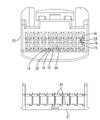
先にハウジング10の構造を簡単に説明する。ハウジング10は、合成樹脂製とされ、図6及び図7に示すように、内部には端子金具30が後方から挿入可能とされるキャビティ11を上下2段、幅方向に8室ずつ並べて備えている。ハウジング10には、下方からリテーナ21を装着可能なリテーナ取付孔12が各キャビティ11の下壁13を前後に分断しつつ開口して設けられている。キャビティ11の下面側には、挿入される端子金具30に弾性的に係止可能なランス14がそれぞれ設けられている。ランス14は、キャビティ11の下壁13のうちリテーナ取付孔12よりも前側部分を切欠することで形成されており、大まかには、前後両端部が支持された両持ち状のアーム部15と、アーム部15の上面幅方向中央に設けられ端子金具30の突起52に係止可能な係止部16とを備えている。
【0010】
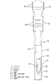
続いて、端子金具30について説明する。端子金具30は、金属板を図1に示す展開形状に打ち抜くと共に曲げ加工を行う、いわゆるプレス成形によって図2ないし図5に示す形状に成形されている。端子金具30は、前側から順に、図示しない雄側の端子金具30と導通接続可能な本体部31と、電線Wの端末に露出した芯線に圧着接続されるワイヤバレル部32と、電線Wの被覆部分にかしめ固定されるインシュレーションバレル部33とから構成されている。このうちワイヤバレル部32とインシュレーションバレル部33は、それぞれ一対ずつかしめ片34,35を有している。
【0011】
本体部31について詳細に説明する。本体部31は、図1に示すように、前後に延出する基板36の両側縁から突設された一対の側板37,38を立ち上げるとともに、図示奥側の側板38から突設された突板40を手前側に折り曲げつつ、その外に手前側の側板37から突設された突板39を折り重ねることで、図2に示すように、全体として前後に開口する略箱形状に成形されるようになっている。図1の奥側の突板40には、奥側へ延設された連結片41を介して前後に延びる舌片42が連結されており、成形時には連結片41を手前側の側板37と基板36の内面に沿うように2度屈曲させるとともに舌片42を基板36の内面に沿って前方へ延出させることで、図7に示すように、片持ち状の弾性接触片45が形成される。また、図1に示すように、連結片41からは奥側へ向けて差込片43が突設されており、成形時にこの差込片43が奥側の側板38に穿設された差込孔44に差し込まれることで、弾性接触片45の前後の位置決めが図られている(図4)。弾性接触片45は、図7に示すように、前部が基板36から離間するように山形に形成されるとともに上方へ弾性変形可能とされており、その頂点部分には、本体部31内に挿入される雄側の端子金具30に対して弾性接触可能な接点部46が膨出形成されている。内側の突板40のうち弾性接触片45に対向する部分には、雄側の端子金具30に対する接圧を高めるための張出部47が内側に張り出して形成されている。また基板36における弾性接触片45の前部に対向する部分には、孔部48が上方に開口して形成されている。また基板36の前端からは、弾性接触片45の前端部とほぼ同じ高さ位置に達する保護片49が立ち上げられることで、弾性接触片45を保護できるようになっている。
【0012】
図1に示すように、手前側の突板39には、隣接する側板37にまたがる形態で凹部50が開設されている。この凹部50は、突板39における長さ方向中央よりも前寄りの位置に配設されるとともに、側板37の手前側縁部を所定幅切欠して形成されている。凹部50は、突板39及び側板37を板厚方向にのみ開口させる四角形状に形成されており、従ってその周縁部が全周にわたって繋げられている。一方、奥側の突板40の側縁部には、凹部50に対応する位置に保持片51が突設されている。この保持片51は、凹部50の長さ寸法よりも若干短い長さ寸法を有している。そして、本体部31の成形時における両突板39,40同士の折り重ね作業時に、保持片51を凹部50内に嵌合させるとともに、図3及び図5に示すように、手前側の側板37における凹部50の切欠縁部(図5の下縁)に保持片51を係合させるようにする。このように、保持片51を凹部50に嵌合させることで、本体部31を略箱形状に保持できるようになっている。なおこの保持片51は、凹部50を通して外部に露出している。また凹部50を介して内側の突板40に形成した張出部47が部分的に外部に露出している。
【0013】
凹部50の周縁前部には、図7に示すように、ランス14の係止部16に係止可能な突起52が叩き出しにより形成されている。この突起52は、図3に示すように、本体部31の幅方向中央位置に配設されるとともに、底面から視て前端側にかけて次第に幅寸法が小さくなる先細り状に形成され、且つ、図2に示すように、正面から視て幅方向中央部分を頂点とする山形に形成されている。また手前側の突板39の後端部からは、図4に示すように、スタビライザ53が突設され、本体部31から側板38に沿って下方へ突き出るように屈曲されている。また本体部31の後端下部の段差部分には、リテーナ21に設けられた係止突部22が係止可能なあご部54が設けられている。
【0014】
次に、端子金具30をキャビティ11内に挿入する作業を説明しつつ必要に応じてハウジング10側の構造を補充して説明する。図7に示すように、ハウジング10に対してリテーナ21を係止突部22がキャビティ11から退避する仮係止位置に装着した状態で、キャビティ11内に端子金具30を後方から挿入すると、突起52がキャビティ11の下面中央に形成された突起挿通凹部17に摺接されるとともに、スタビライザ53がキャビティ11の下面側縁に形成されたスタビライザ挿通凹部18に摺接されることで、挿入動作が円滑に案内される。端子金具30が所定深さに達すると、図8に示すように、端子金具30の前端下部がランス14の係止部16のテーパ状の後面を押圧することで、アーム部15が前後の連結部分を撓み支点として下方へ撓まされて、前後方向の略中央部分が最下端となる略弓形に変形する。
【0015】
端子金具30が正規深さまで挿入されると、図9に示すように、アーム部15が弾性復帰するとともに係止部16が凹部50内に進入して、係止部16が突起52と、突起52の両側方に配された凹部50の周縁前部とにまたがって係止されることで端子金具30の一次係止が図られる。その後、リテーナ21を上方へ移動させることで、係止突部22がキャビティ11内に進入する本係止位置に達し、図10に示すように、係止突部22が端子金具30のあご部54に係止することで、端子金具30の二次係止が図られる。
【0016】
さて、上記した雌コネクタにおいて、キャビティ11内に端子金具30を挿入するのに必要な力を低減するよう要請があった場合には、適切な設計変更を行って対応することになる。設計変更を行うにあたっては、端子金具30の挿入力は、主にランス14を撓ませるのに必要な力によって決定されることから、ランス14の構造を変更することが考えられる。
【0017】
ランス14のアーム部15は、図6及び図7に示すように、後端部が全幅にわたってキャビティ11の下壁13に連結されているのに対し、前端部については、係止部16を前方へ型抜きする都合上中央部分に型抜き孔19が形成されることで二股状に分割されており、残された両側部がそれぞれキャビティ11の前壁20に連結されている。従って、ランス14を撓ませるのに必要な力は、主にアーム部15の後側の支点から端子金具30が係止部16を押圧する作用点までの距離によって決定されることになり、その距離が長いほど必要な力は小さく済む。一方、係止部16の長さ寸法は、端子金具30に対する抜け止め力に比例するため、必要最低限の長さは確保する必要がある。従って、係止部16の長さ寸法必要最低限確保した上でその配設位置を前方に移動させた方がランス14を撓ませるのに必要な力、すなわち端子金具30の挿入力を低減することができる。
【0018】
このように端子金具30の挿入力の低減を図るべく、係止部16の配設位置を前方に変更した場合には、それに対応して端子金具30の凹部50の配設位置を前方に変更する必要がある。その場合でも、図1に示すように、凹部50と保持片51とは別々の突板39,40に設けられ、言い換えると凹部50を内側の突板40のうち保持片51を突出させている縁部から離れた位置に配設しているから、凹部50の配設位置を前方に移動させたとしても、その凹部50とは無関係に内側の突板40のうち保持片51を突出させている縁部を本体部31の軸線方向に連続する形態のままとすることができ、保持片51の長さ寸法を十分に確保することができる。従って、外側の突板39における凹部50の配設位置の自由度が高くすることができ、ランス14の係止部16の位置が前方へ移動した場合でも、容易に対応することができ、もって雌コネクタにおいて端子金具30の挿入力を低減するという目的を達成することが可能となる。
【0019】
しかも、凹部50をその開口縁が全周にわたって繋がる形態としたから、凹部50を設けた突板39を本体部31の軸線方向について連続する形状とすることができ、強度的に優れる。さらには、凹部50が保持片51を嵌合する保持孔としての機能を兼用しているから、別途に本体部31に保持孔を開設した場合と比較して端子金具30の構造を簡素化できるとともに強度的にも優れる。
【0020】
<参考例>
参考例を図11によって説明する。上記した第1実施形態では、凹部と保持片とを別々の突板に設けた場合を示したが、この参考例では、同じ突板に凹部と保持片とを設けた場合を示す。
【0021】
図11に示すように、外側の突板39Aにおける前寄りの位置には、凹部50Aが開設されている。この凹部50Aは、四角形状とされ、その開口縁が全周にわたって繋げられている。この突板39Aの手前側縁部には、前後一対の保持片51Aが突設されており、両保持片51Aは、手前側の側板37Aに穿設された保持孔55内に嵌合されることで、本体部31Aを略箱形状に保持できるようになっている。このように凹部50Aが突板39Aのうち保持片51Aを突出させている縁部を切り欠くことなく離れた位置に形成されているから、保持片51Aが凹部50Aによって分断されるようなことがなく、保持片51Aの長さ寸法を十分に確保することができる。その上で、保持片51Aとは無関係に凹部50Aの配設位置を設定することができ、これにより、図11のように前側の保持片51Aと凹部50Aとを前後方向について重なる配置とすることができる。もって、コネクタの設計変更によってランス14の係止部16の配設位置が移動した場合でも容易に対応することができる。
なお、その他の構造、作用及び効果は上記した第1実施形態と同様であるため重複する説明は省略する。
【0022】
<他の実施形態>
本発明は上記記述及び図面によって説明した実施形態に限定されるものではなく、例えば次のような実施形態も本発明の技術的範囲に含まれ、さらに、下記以外にも要旨を逸脱しない範囲内で種々変更して実施することができる。
【0023】
(1)上記した実施形態では、雌側の端子金具を示したが、略箱形の本体部から前方へタブを突設した雄側の端子金具についても本発明は適用可能である。
(2)上記した実施形態では、両持ち状のランスを備えるハウジングに挿入する端子金具について示したが、片持ち状のランスを備えるハウジングに挿入するものにも本発明は適用可能である。
【図面の簡単な説明】
【図1】本発明の第1実施形態に係る端子金具の展開図
【図2】端子金具の正面図
【図3】端子金具の底面図
【図4】端子金具の右側面図
【図5】端子金具の左側面図
【図6】ハウジングとリテーナの正面図
【図7】ハウジングにリテーナを仮係止位置に装着し、端子金具を挿入する前の状態を示す側断面図
【図8】端子金具を挿入する途中の状態を示す側断面図
【図9】端子金具がランスにより一次係止された状態を示す側断面図
【図10】リテーナが本係止位置に達し、端子金具が二次係止された状態を示す側断面図
【図11】 参考例に係る端子金具の斜視図
【図12】従来例の斜視図
【符号の説明】
10…ハウジング
14…ランス
30…端子金具
31,31A…本体部
36…基板
37,37A,38…側板
39,39A…突板(外側の突板)
40…突板
50,50A…凹部(被係止凹部、保持孔)
51,51A…保持片
55…保持孔[0001]
BACKGROUND OF THE INVENTION
The present invention relates to a terminal fitting having a substantially box-shaped main body.
[0002]
[Prior art]
Conventionally, it is known that a terminal fitting inserted into a housing is provided with a step-shaped recess, and a lance on the housing side is locked to the recess, and an example thereof is disclosed in JP 2000-294334 A. It is described in the publication. In order to form such a recess in the terminal fitting, for example, as shown in FIG. 12, a
[0003]
[Problems to be solved by the invention]
By the way, when the housing for housing the terminal fitting is changed in design, for example, when the position of the lance is moved forward, the recess 7 in the terminal fitting is provided at a position ahead of the position in FIG. There is a need. However, the protruding plate 5 is divided into two front and rear by the concave portion 7 and the
The present invention has been completed based on the above-described circumstances, and an object thereof is to increase the degree of freedom of the arrangement position of the locked recess.
[0004]
[Means for Solving the Problems]
As means for achieving the above object, the invention of
[0006]
[Action and effect of the invention]
<Invention of
Since the holding piece is not divided by the locked recess, the length of the holding piece in the axial direction can be sufficiently secured, and the locked recess can be arranged independently of the holding piece. The installation position can be set. That is, since the degree of freedom of the arrangement position of the locked recess with respect to the protruding plate can be increased, for example, even when the design of the housing is changed and the arrangement position of the lance is moved, it is possible to easily cope with it.
Further, the structure of the terminal fitting can be simplified, and the strength is further improved.
[0008]
DETAILED DESCRIPTION OF THE INVENTION
Hereinafter, embodiments of the present invention will be described with reference to the accompanying drawings.
<First Embodiment>
A first embodiment of the present invention will be described with reference to FIGS. In this embodiment, a female terminal fitting housed in a female connector housing is shown. In the following description, the insertion direction of the terminal fitting with respect to the housing is assumed to be the front.
[0009]
First, the structure of the
[0010]
Subsequently, the terminal fitting 30 will be described. The
[0011]
The
[0012]
As shown in FIG. 1, the
[0013]
As shown in FIG. 7, a
[0014]
Next, while explaining the operation of inserting the terminal fitting 30 into the
[0015]
When the terminal fitting 30 is inserted to the normal depth, as shown in FIG. 9, the
[0016]
Now, in the above-described female connector, if there is a request to reduce the force required to insert the terminal fitting 30 into the
[0017]
As shown in FIGS. 6 and 7, the
[0018]
Thus, in order to reduce the insertion force of the terminal fitting 30, when the arrangement position of the locking
[0019]
In addition, since the
[0020]
< Reference example >
A reference example will be described with reference to FIG. In the first embodiment described above, the case where the concave portion and the holding piece are provided on separate protruding plates is shown, but in this reference example , the case where the concave portion and the holding piece are provided on the same protruding plate is shown.
[0021]
As shown in FIG. 11, a
Other structures, operations, and effects are the same as those in the first embodiment described above, and thus redundant description is omitted.
[0022]
<Other embodiments>
The present invention is not limited to the embodiments described with reference to the above description and drawings. For example, the following embodiments are also included in the technical scope of the present invention, and further, within the scope not departing from the gist of the invention other than the following. Various modifications can be made .
[0023]
( 1 ) In the above-described embodiment, the female terminal fitting is shown. However, the present invention can also be applied to a male terminal fitting having a tab projecting forward from a substantially box-shaped main body.
( 2 ) In the above-described embodiment, the terminal metal fitting inserted into the housing provided with the both-sided lance has been described. However, the present invention can also be applied to those inserted into the housing provided with the cantilevered lance.
[Brief description of the drawings]
FIG. 1 is a development view of a terminal fitting according to a first embodiment of the present invention. FIG. 2 is a front view of the terminal fitting. FIG. 3 is a bottom view of the terminal fitting. Left side view of the terminal bracket [Fig. 6] Front view of the housing and retainer [Fig. 7] Side sectional view showing the state before the retainer is inserted into the housing in the temporary locking position and the terminal bracket is inserted [Fig. 8] Terminal FIG. 9 is a side sectional view showing a state in which the metal fitting is being inserted. FIG. 9 is a side sectional view showing a state in which the terminal fitting is primarily locked by the lance. FIG. FIG. 11 is a perspective view of a terminal fitting according to a reference example . FIG. 12 is a perspective view of a conventional example.
DESCRIPTION OF
40: Projecting
51, 51A ... Holding
Claims (1)
前記両突板のうち外側の前記突板には、ハウジング内に挿入されたときにハウジング側に設けられたランスが進入して係止可能とされる被係止凹部が開設されていて、この被係止凹部が、前記外側の突板における突出端側の縁部を残しつつ基端側の縁部を側方へ開口させる形態で、且つその長さ寸法が全幅領域にわたって一定となる形態で形成されるとともに、その前縁に対して前記ランスが係止可能とされていて、
前記両突板のうち内側の突板における突出端側の縁部には、保持片が設けられるとともに、前記被係止凹部が前記保持片を嵌合可能な保持孔を兼用していて、前記保持片が前記被係止凹部により露出した前記側板の縁部に対して載せられた状態で係合されることで、前記本体部を所定形状に保持できるようになっており、
さらには前記内側の突板のうち前記保持片を突出させている縁部が前記本体部の軸線方向に沿って連続していて、前記保持片は、その縁部に沿って延びる形態とされるとともに前記被係止凹部の長さ寸法よりも短い長さ寸法をもって形成されていることを特徴とする端子金具。A main body formed entirely in a box shape by a substrate, a pair of side plates raised from both side edges of the substrate, and a pair of projecting plates protruding from both side plates and bent so as to overlap each other Have
Of the two protruding plates, the outer protruding plate is provided with a locked recess that allows a lance provided on the housing side to enter and be locked when inserted into the housing. The stop recess is formed in such a form that the edge on the base end side is opened sideways while leaving the edge on the protruding end side of the outer protrusion plate, and the length dimension is constant over the entire width region. In addition, the lance can be locked to its front edge,
Wherein the edge of the projecting end side of the inner veneer of both veneer, with hold pieces are provided, said the engagement recess has been shared with mateable holding hole of the holding piece, the holding The main body portion can be held in a predetermined shape by being engaged with a piece placed on the edge of the side plate exposed by the locked recess,
Furthermore, the edge part which makes the said holding piece protrude among the said inner side protrusion plates is continuing along the axial direction of the said main-body part, and the said holding piece is made into the form extended along the edge part. A terminal fitting having a length shorter than the length of the locked recess.
Priority Applications (7)
| Application Number | Priority Date | Filing Date | Title |
|---|---|---|---|
| JP2001272453A JP3801889B2 (en) | 2001-09-07 | 2001-09-07 | Terminal fitting |
| DE60208129T DE60208129T2 (en) | 2001-09-07 | 2002-08-30 | Terminal contact, connector equipped therewith and method of making the terminal contact |
| EP02019458A EP1294057B1 (en) | 2001-09-07 | 2002-08-30 | A terminal fitting, a connector provided therewith and a method for forming a terminal fitting |
| DE60218094T DE60218094T2 (en) | 2001-09-07 | 2002-08-30 | Terminal contact, connector equipped therewith and method of making the terminal contact |
| EP02019457A EP1294056B1 (en) | 2001-09-07 | 2002-08-30 | Terminal fitting, connector provided therewith and method for producing the terminal fitting |
| US10/234,295 US6733346B2 (en) | 2001-09-07 | 2002-09-03 | Terminal fitting, a connector provided therewith and a method for forming a terminal fitting |
| US10/238,132 US6752660B2 (en) | 2001-09-07 | 2002-09-09 | Terminal fitting, connector provided therewith and method for producing the terminal fitting |
Applications Claiming Priority (1)
| Application Number | Priority Date | Filing Date | Title |
|---|---|---|---|
| JP2001272453A JP3801889B2 (en) | 2001-09-07 | 2001-09-07 | Terminal fitting |
Publications (2)
| Publication Number | Publication Date |
|---|---|
| JP2003086281A JP2003086281A (en) | 2003-03-20 |
| JP3801889B2 true JP3801889B2 (en) | 2006-07-26 |
Family
ID=19097824
Family Applications (1)
| Application Number | Title | Priority Date | Filing Date |
|---|---|---|---|
| JP2001272453A Expired - Lifetime JP3801889B2 (en) | 2001-09-07 | 2001-09-07 | Terminal fitting |
Country Status (4)
| Country | Link |
|---|---|
| US (1) | US6733346B2 (en) |
| EP (1) | EP1294057B1 (en) |
| JP (1) | JP3801889B2 (en) |
| DE (1) | DE60208129T2 (en) |
Families Citing this family (24)
| Publication number | Priority date | Publication date | Assignee | Title |
|---|---|---|---|---|
| MXPA03003493A (en) * | 2000-10-24 | 2005-01-25 | Thomson Licensing Sa | Method of collecting data using an embedded media player page. |
| FR2816157A1 (en) * | 2000-10-31 | 2002-05-03 | Thomson Multimedia Sa | PROCESS FOR PROCESSING DISTRIBUTED VIDEO DATA TO BE VIEWED ON SCREEN AND DEVICE IMPLEMENTING THE METHOD |
| JP2003157924A (en) * | 2001-11-22 | 2003-05-30 | Sumitomo Wiring Syst Ltd | Female side terminal fitting |
| DE10252832B4 (en) * | 2001-11-22 | 2006-11-30 | Sumitomo Wiring Systems, Ltd., Yokkaichi | Terminal fitting and method of forming the same |
| JP3415137B1 (en) * | 2002-06-24 | 2003-06-09 | 住友電装株式会社 | connector |
| EP1619760B1 (en) * | 2003-01-16 | 2007-09-19 | Sumitomo Wiring Systems, Ltd. | A jig and a method for withdrawing a terminal in a connector |
| JP2006216313A (en) * | 2005-02-02 | 2006-08-17 | Sumitomo Wiring Syst Ltd | Terminal fitting |
| JP2006216316A (en) * | 2005-02-02 | 2006-08-17 | Sumitomo Wiring Syst Ltd | Terminal fitting |
| US7186189B2 (en) * | 2005-07-01 | 2007-03-06 | Ben Huang | Panel grip with modified seam |
| JP4552781B2 (en) * | 2005-07-05 | 2010-09-29 | 住友電装株式会社 | Terminal fitting |
| JP2007194047A (en) * | 2006-01-18 | 2007-08-02 | Sumitomo Wiring Syst Ltd | Terminal fitting |
| JP4743109B2 (en) * | 2006-12-18 | 2011-08-10 | 住友電装株式会社 | Terminal fittings and connectors |
| JP2009245655A (en) * | 2008-03-28 | 2009-10-22 | Yazaki Corp | Female terminal structure and its chain terminal |
| JP4930439B2 (en) * | 2008-04-04 | 2012-05-16 | 住友電装株式会社 | Terminal fitting |
| JP5233822B2 (en) * | 2009-04-24 | 2013-07-10 | 住友電装株式会社 | Terminal fitting |
| AT511757B1 (en) * | 2011-08-12 | 2013-06-15 | Eaton Gmbh | METHOD FOR PRODUCING AN ELECTRIC CONTACT CARRIER |
| EP3326245A4 (en) | 2015-07-23 | 2019-03-13 | Molex, LLC | Terminal fitting |
| JP6211563B2 (en) | 2015-07-31 | 2017-10-11 | 矢崎総業株式会社 | Terminal bracket |
| JP2018018703A (en) | 2016-07-28 | 2018-02-01 | 矢崎総業株式会社 | connector |
| CN110073555B (en) * | 2017-01-23 | 2021-04-27 | 莫列斯有限公司 | Electrical terminal and connector assembly |
| JP6781934B2 (en) | 2017-04-26 | 2020-11-11 | 住友電装株式会社 | Terminal |
| JP2020035541A (en) * | 2018-08-27 | 2020-03-05 | 矢崎総業株式会社 | Connection terminal |
| JP7005117B2 (en) * | 2019-05-29 | 2022-01-21 | 矢崎総業株式会社 | Wires with terminals and wire harnesses |
| JP7032462B2 (en) * | 2020-02-18 | 2022-03-08 | 矢崎総業株式会社 | Connecting terminal |
Family Cites Families (12)
| Publication number | Priority date | Publication date | Assignee | Title |
|---|---|---|---|---|
| US5362260A (en) * | 1993-08-03 | 1994-11-08 | Molex Incorporated | Electrical connector with improved terminal latching system |
| JPH08213082A (en) * | 1994-10-21 | 1996-08-20 | Whitaker Corp:The | Electric terminal and electric connector using it |
| DE69602669T2 (en) * | 1995-03-27 | 1999-11-11 | Whitaker Corp | Electrical connector |
| JPH1012309A (en) * | 1996-06-25 | 1998-01-16 | Yazaki Corp | Connector |
| TW313343U (en) * | 1997-01-17 | 1997-08-11 | Su-Lan Yanglee | Electrical connector device |
| JP3494850B2 (en) * | 1997-06-12 | 2004-02-09 | 矢崎総業株式会社 | Terminal for connector |
| WO1998059394A1 (en) * | 1997-06-24 | 1998-12-30 | Siemens Aktiengesellschaft | Flat plug contact organ for electrical connectors |
| FR2769413B1 (en) * | 1997-10-03 | 1999-11-26 | Proner Comatel Sa | FEMALE ELECTRIC CONTACT |
| DE10012262C2 (en) * | 1999-03-16 | 2002-10-24 | Sumitomo Wiring Systems | female contact |
| JP3601765B2 (en) * | 1999-04-05 | 2004-12-15 | 矢崎総業株式会社 | Connector locking structure |
| JP3542072B2 (en) | 1999-04-09 | 2004-07-14 | 矢崎総業株式会社 | Wire rattling prevention structure of connector |
| JP2001160448A (en) * | 1999-12-02 | 2001-06-12 | Sumitomo Wiring Syst Ltd | Connector |
-
2001
- 2001-09-07 JP JP2001272453A patent/JP3801889B2/en not_active Expired - Lifetime
-
2002
- 2002-08-30 EP EP02019458A patent/EP1294057B1/en not_active Expired - Lifetime
- 2002-08-30 DE DE60208129T patent/DE60208129T2/en not_active Expired - Lifetime
- 2002-09-03 US US10/234,295 patent/US6733346B2/en not_active Expired - Lifetime
Also Published As
| Publication number | Publication date |
|---|---|
| DE60208129D1 (en) | 2006-01-26 |
| US6733346B2 (en) | 2004-05-11 |
| EP1294057A3 (en) | 2003-04-16 |
| US20030049975A1 (en) | 2003-03-13 |
| DE60208129T2 (en) | 2006-08-24 |
| EP1294057B1 (en) | 2005-12-21 |
| EP1294057A2 (en) | 2003-03-19 |
| JP2003086281A (en) | 2003-03-20 |
Similar Documents
| Publication | Publication Date | Title |
|---|---|---|
| JP3801889B2 (en) | Terminal fitting | |
| US7014505B1 (en) | Connector | |
| EP2416452B1 (en) | Terminal fitting | |
| JP2004039498A (en) | Connector | |
| JP4032925B2 (en) | connector | |
| JP2010040183A (en) | Connector | |
| JP2005019282A (en) | Connector | |
| JP4268074B2 (en) | connector | |
| JP4385923B2 (en) | Terminal fitting and connector using the same | |
| JP4030673B2 (en) | Female terminal of electrical connector | |
| JP5195661B2 (en) | connector | |
| JP4273681B2 (en) | Terminal fitting | |
| JP2723432B2 (en) | Female terminal fitting | |
| JP7384611B2 (en) | Housing and connector | |
| JP2006324048A (en) | Connector | |
| JP3804489B2 (en) | connector | |
| JP3753018B2 (en) | connector | |
| JP2010003465A (en) | Female connector | |
| JP3888185B2 (en) | connector | |
| JP3823206B2 (en) | connector | |
| JP3775269B2 (en) | connector | |
| JP4165089B2 (en) | connector | |
| JP4067606B2 (en) | Slide switch | |
| JP2003077575A (en) | Connector | |
| JPH10247542A (en) | Terminal |
Legal Events
| Date | Code | Title | Description |
|---|---|---|---|
| A621 | Written request for application examination |
Free format text: JAPANESE INTERMEDIATE CODE: A621 Effective date: 20040511 |
|
| A977 | Report on retrieval |
Free format text: JAPANESE INTERMEDIATE CODE: A971007 Effective date: 20050920 |
|
| A131 | Notification of reasons for refusal |
Free format text: JAPANESE INTERMEDIATE CODE: A131 Effective date: 20050929 |
|
| A521 | Written amendment |
Free format text: JAPANESE INTERMEDIATE CODE: A523 Effective date: 20051128 |
|
| A131 | Notification of reasons for refusal |
Free format text: JAPANESE INTERMEDIATE CODE: A131 Effective date: 20060117 |
|
| A521 | Written amendment |
Free format text: JAPANESE INTERMEDIATE CODE: A523 Effective date: 20060317 |
|
| TRDD | Decision of grant or rejection written | ||
| A01 | Written decision to grant a patent or to grant a registration (utility model) |
Free format text: JAPANESE INTERMEDIATE CODE: A01 Effective date: 20060413 |
|
| A61 | First payment of annual fees (during grant procedure) |
Free format text: JAPANESE INTERMEDIATE CODE: A61 Effective date: 20060426 |
|
| R150 | Certificate of patent or registration of utility model |
Free format text: JAPANESE INTERMEDIATE CODE: R150 Ref document number: 3801889 Country of ref document: JP Free format text: JAPANESE INTERMEDIATE CODE: R150 |
|
| FPAY | Renewal fee payment (event date is renewal date of database) |
Free format text: PAYMENT UNTIL: 20090512 Year of fee payment: 3 |
|
| FPAY | Renewal fee payment (event date is renewal date of database) |
Free format text: PAYMENT UNTIL: 20100512 Year of fee payment: 4 |
|
| FPAY | Renewal fee payment (event date is renewal date of database) |
Free format text: PAYMENT UNTIL: 20100512 Year of fee payment: 4 |
|
| FPAY | Renewal fee payment (event date is renewal date of database) |
Free format text: PAYMENT UNTIL: 20110512 Year of fee payment: 5 |
|
| FPAY | Renewal fee payment (event date is renewal date of database) |
Free format text: PAYMENT UNTIL: 20120512 Year of fee payment: 6 |
|
| FPAY | Renewal fee payment (event date is renewal date of database) |
Free format text: PAYMENT UNTIL: 20120512 Year of fee payment: 6 |
|
| FPAY | Renewal fee payment (event date is renewal date of database) |
Free format text: PAYMENT UNTIL: 20130512 Year of fee payment: 7 |
|
| FPAY | Renewal fee payment (event date is renewal date of database) |
Free format text: PAYMENT UNTIL: 20140512 Year of fee payment: 8 |
|
| EXPY | Cancellation because of completion of term |