JP2010040183A - Connector - Google Patents
Connector Download PDFInfo
- Publication number
- JP2010040183A JP2010040183A JP2008198058A JP2008198058A JP2010040183A JP 2010040183 A JP2010040183 A JP 2010040183A JP 2008198058 A JP2008198058 A JP 2008198058A JP 2008198058 A JP2008198058 A JP 2008198058A JP 2010040183 A JP2010040183 A JP 2010040183A
- Authority
- JP
- Japan
- Prior art keywords
- cavity
- housing
- lance
- guide groove
- terminal fitting
- Prior art date
- Legal status (The legal status is an assumption and is not a legal conclusion. Google has not performed a legal analysis and makes no representation as to the accuracy of the status listed.)
- Granted
Links
Images

Landscapes
- Connector Housings Or Holding Contact Members (AREA)
Abstract
Description
本発明は、コネクタに関する。 The present invention relates to a connector.
特許文献1に記載のコネクタは、端子金具と、端子金具を挿入可能な複数のキャビティを有するハウジングとを備え、端子金具には逆挿防止用のスタビライザが突設され、キャビティの内壁には端子金具の挿入に伴ってスタビライザが進入するガイド溝が凹設されている。 The connector described in Patent Document 1 includes a terminal fitting and a housing having a plurality of cavities into which the terminal fitting can be inserted. A stabilizer for preventing reverse insertion protrudes from the terminal fitting, and a terminal is provided on the inner wall of the cavity. A guide groove into which the stabilizer enters as the metal fitting is inserted is recessed.
ハウジングには、ガイド溝が凹設されたキャビティの内壁とこれに隣接するキャビティの内壁との間に、両キャビティ間を仕切る隔壁が設けられている。ガイド溝は、隔壁において、前後方向に細長く延びてハウジングの後面のみに開口する有底溝として構成されている。
ところで、上記隣接するキャビティ間を仕切る隔壁は十分過ぎるほどの厚みをもっており、その分、ハウジングが高背化して、コネクタ全体として大型化する嫌いがある。 By the way, the partition wall partitioning the adjacent cavities has a thickness that is too large, and accordingly, the housing becomes taller and there is a hate to increase the size of the entire connector.
本発明は上記のような事情に基づいて完成されたものであって、コネクタの大型化を回避することを目的とする。 The present invention has been completed based on the above circumstances, and an object thereof is to avoid an increase in the size of a connector.
上記の目的を達成するための手段として、請求項1の発明は、端子金具と、前記端子金具を挿入可能な複数のキャビティを有するハウジングとを備え、前記端子金具には、この端子金具の前記ハウジングへの逆挿入を防止するためのスタビライザが突設されており、前記キャビティの内壁には、前記スタビライザが進入するガイド溝が凹設されているコネクタであって、前記ハウジングにおける前記ガイド溝は、このガイド溝が凹設された前記キャビティと隣接するキャビティに通じる連通口を有している構成としたところに特徴を有する。 As means for achieving the above object, the invention of claim 1 includes a terminal fitting and a housing having a plurality of cavities into which the terminal fitting can be inserted, and the terminal fitting includes the terminal fitting. A stabilizer for preventing reverse insertion into the housing is protruded, and a guide groove into which the stabilizer enters is recessed on the inner wall of the cavity, and the guide groove in the housing is Further, the present invention is characterized in that the guide groove has a communication port communicating with the cavity adjacent to the recessed cavity and the adjacent cavity.
請求項2の発明は、請求項1に記載のものにおいて、前記キャビティの内壁には前記端子金具を弾性的に係止するランスが撓み可能に突出して設けられ、前記ハウジングにおける前記ガイド溝の前記連通口は、前記隣接するキャビティの内壁に突出して設けられた前記ランスと対向して配置されているところに特徴を有する。 According to a second aspect of the present invention, in the first aspect of the present invention, a lance that elastically locks the terminal fitting is provided on the inner wall of the cavity so as to be flexibly protruded, and the guide groove of the housing is provided with the lance. The communication port is characterized in that it is disposed so as to face the lance provided so as to protrude from the inner wall of the adjacent cavity.
請求項3の発明は、請求項2に記載のものにおいて、前記ランスには、前記連通口と対向する面に、前記連通口に通じる溝部が外部から視認可能に切り欠いて設けられているところに特徴を有する。 According to a third aspect of the present invention, in the lance according to the second aspect, the lance is provided with a groove portion leading to the communication port, which is notched so as to be visible from the outside, on a surface facing the communication port. It has the characteristics.
請求項4の発明は、請求項2又は3に記載のものにおいて、前記連通口が前記ランスの根元部分の幅方向中央部と対向して配置されているところに特徴を有する。 The invention according to claim 4 is characterized in that, in the invention according to claim 2 or 3, the communication port is arranged to face the central portion in the width direction of the root portion of the lance.
<請求項1の発明>
ガイド溝がこのガイド溝が凹設されたキャビティと隣接するキャビティに通じる連通口を有しているため、ガイド溝が隣接するキャビティに非連通とされる場合に比べ、両キャビティ間のピッチを狭めることが可能となり、ハウジングが低背化され、ひいてはコネクタ全体の小型化を図れる。
<Invention of Claim 1>
Since the guide groove has a communication port that communicates with the cavity where the guide groove is recessed and the adjacent cavity, the pitch between the two cavities is narrower than when the guide groove is not connected to the adjacent cavity. This makes it possible to reduce the height of the housing and thus reduce the overall size of the connector.
<請求項2の発明>
ガイド溝の連通口が隣接するキャビティの内壁に突出して設けられたランスと対向して配置されているため、連通口にスタビライザが臨むという事情があっても、ランスの介在によってこのスタビライザが突設された端子金具と隣接するキャビティに挿入された端子金具との間が絶縁状態に保たれる。
<Invention of Claim 2>
Because the guide groove communication port is located opposite to the lance that protrudes from the inner wall of the adjacent cavity, even if there is a situation where the stabilizer faces the communication port, this stabilizer is projected by the intervention of the lance. The insulated terminal fitting and the terminal fitting inserted into the adjacent cavity are kept in an insulated state.
<請求項3の発明>
ランスには連通口に通じる溝部が外部から視認可能に切り欠いて設けられているため、溝部を通して連通口を覗き見ることにより、連通口に臨むスタビライザを確認することができ、ひいては端子金具の挿入が適正になされているのが否かを確認することができる。
<Invention of Claim 3>
The lance has a groove that leads to the communication port so that it can be seen from the outside. By looking through the groove, you can see the stabilizer facing the communication port, and insert the terminal fitting. It can be confirmed whether or not is properly performed.
<請求項4の発明>
連通口がランスの根元部分の幅方向中央部と対向して配置されているため、ガイド溝に挿入された端子金具のスタビライザがランスによって確実に保護されるとともに、ランスの撓み動作のバランス性が良好となる。
<Invention of Claim 4>
Since the communication port is arranged to face the center in the width direction of the base portion of the lance, the stabilizer of the terminal fitting inserted into the guide groove is reliably protected by the lance, and the balance of the bending operation of the lance is improved. It becomes good.
<実施形態1>
本発明の実施形態1を図1ないし図5によって説明する。本実施形態に係るコネクタは、端子金具10とハウジング30とを備えている。ハウジング30は図示しない相手側ハウジングと嵌合可能とされている。なお、以下の説明において前後方向については相手側ハウジングに対する嵌合面側を前方として説明する。
<Embodiment 1>
A first embodiment of the present invention will be described with reference to FIGS. The connector according to this embodiment includes a terminal fitting 10 and a
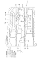
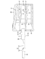
端子金具10は導電性金属板を曲げ加工等して形成され、図2に示すように、前部に角筒状の接続部11を有し、後部にオープンバレル状のバレル部12を有している。接続部11にはハウジング30と相手側ハウジングとの嵌合に伴って前方から図示しない相手側端子金具の雄タブが挿入され、その内部において両端子金具の導通がとられる。接続部11の一壁には、スタビライザ13が切り起こしにより突出して設けられている。スタビライザ13は、前後方向に沿った板状をなし、接続部11の上面の幅方向一側に配置された矩形板状で大型の上側スタビライザ14と、接続部11の下面の幅方向他側に配置された台形板状で小型の下側スタビライザ15とからなる。かかるスタビライザ13は、ハウジング30のキャビティ33(後述する)内に端子金具10が正逆(上下左右)反転した姿勢で挿入されるのを防止するとともに、キャビティ33内への端子金具10の挿入動作を案内する役割をはたす。接続部11の上面には、図1に示すように、スタビライザ13の切り起こしに伴って凹み形状をなす係止受部16が設けられている。係止受部16はランス37の係止部44(後述する)を受容可能とされている。バレル部12は、前部に電線90の端末芯線にかしめ付けられるワイヤバレル17を有するとともに、後部に電線90の端末被覆にかしめ付けられるインシュレーションバレル18を有している。
The
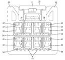
ハウジング30は合成樹脂製であって、図3に示すように、全体として角ブロック状をなし、その上面の幅方向中央部に相手側ハウジングを嵌合状態に保持するロックアーム31が設けられている。ロックアーム31はハウジング30の上面前端から後方へ向けて撓み可能に延出する形態とされている。またハウジング30の上面には、図5に示すように、ロックアーム31を挟んだ両側に、一対の保護壁32が前後方向に延びて設けられている。保護壁32の上端はロックアーム31の上端と同じかそれより高く、ロックアーム31が保護壁32によって保護状態に置かれている。
The
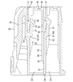
ハウジング30の内部には、高さ方向に複数段、詳細には2段でかつ幅方向に複数列のキャビティ33が設けられている。キャビティ33は、前後方向に延出してハウジング30の後面に開口する形態とされ、その後面開口を通して後方から端子金具10が挿入可能とされている。ハウジング30には、図4に示すように、キャビティ33の前面を仕切って端子金具10の前止まりをなす前壁34が設けられている。前壁34には雄タブの挿通孔35がキャビティ33に連通して設けられ、前壁34の前面における挿通孔35の孔周りには雄タブを誘い込むためのタブ案内面36が前方へラッパ状に拡開して設けられている。
A plurality of
また、ハウジング30におけるキャビティ33の内壁の上面には、端子金具10の後方への抜け止めをなす片持ち状のランス37が撓み可能に設けられている。ランス37の幅方向中心はキャビティ33の幅方向中心より一側に偏心しており、ランス37の幅方向他側面とこれに対向するキャビティ33の内側面との間は、上側スタビライザ14が進入可能な挿入溝38とされている。挿入溝38の断面形状は、上側スタビライザ14の外形形状に沿った縦長スリット状をなしている。
In addition, a cantilever lance 37 that prevents the terminal fitting 10 from coming off backward is provided on the upper surface of the inner wall of the
ランス37は、キャビティ33の内壁の前後方向中間部において前方へ行くに従って次第に肉盛りされてキャビティ33内に進入する形態の根元部41と、根元部41の前端から前方へほぼ真直ぐ突出する本体部42とからなり、根元部41を支点として本体部42が高さ方向に撓み変形可能とされている。根元部41の後部の幅方向中央部には、縦長スリット状の逃がし溝43が前後方向に延出するとともに後面に開口して設けられている。逃がし溝43によって根元部41の撓み動作の円滑性が確保されている。また、本体部42の先端部には、端子金具10の正規挿入時に、端子金具10の係止受部16内に進入して係止受部16の前端縁に当接可能な係止部44が下向きに突出して設けられている。
The
ハウジング30の前面には、図4に示すように、ランス37の前面部分を成形する型材の抜きによって開口される型抜き孔45が設けられている。型抜き孔45内には挿入溝38の前方を覆う略逆Lの字の支柱壁46が立ち上げて設けられている。また、ハウジング30の前壁34には、型抜き孔45の前端開口下縁と挿通孔35の前端開口上縁とをつなぐ形態の切欠溝47が高さ方向に設けられている。端子金具10の係止状態を解除する際には、切欠溝47を通して型抜き孔45内に解除治具(図示せず)を挿通可能とされている。
As shown in FIG. 4, the
ハウジング30におけるキャビティ33の内壁の下面後端部には、図3に示すように、端子金具10のインシュレーションバレル18と対応する位置に、基準面51が構成されている。そして、キャビティ33の内壁には、テーパ面52を介して基準面51より一段高い位置に、端子金具10の接続部11を支持可能な支持面53が構成されている。端子金具10のバレル部12の底面は、基準面51、テーパ面52、支持面53にほぼ沿った段付き形状をなしている。
As shown in FIG. 3, a
ハウジング30におけるキャビティ33の内壁には、テーパ面52から支持面53にかけて、下側スタビライザ15が進入可能なガイド溝54が凹設されている。ガイド溝54の断面形状は下側スタビライザ15の外形形状に沿った縦長スリット状をなしている。ガイド溝54の溝底面は、基準面51にほぼ面一で連なりつつ全体として前後方向にほぼ真直ぐ延びる形態とされている。
A
上段のキャビティ33におけるガイド溝54の溝底面及び基準面51は、隣接する下段のキャビティ33の内壁上面のうちランス37の根元部41より前方領域の上面とほぼ同じ高さ位置に揃えられている。したがって、ガイド溝54におけるランス37の根元部41より前方領域は下段のキャビティ33に連通することとなり、ここが本発明の連通口55として構成されている。換言すれば、上段のキャビティ33におけるガイド溝54の連通口55は下段のキャビティ33におけるランス37の根元部41の前端に連なっている。この連通口55は、ガイド溝54の前端部にあって、その前端がランス37の本体部42の前端より後方に位置し、本体部42の上面と対向する位置に配置されている。また、連通口55は、この連通口55を除くガイド溝54の領域と前後方向に段差なく真直ぐ連なる形態をなしている。連通口55が下段のキャビティ33と連通することにより、ガイド溝54が高さ方向に関して下段のキャビティ33側にシフトさせられることとなり、これによって上下の両キャビティ33間を仕切る隔壁56の厚みが薄くなっている。なお、ランス37の本体部42の上面とランス37の根元部41より前方領域の上面との間は、ランス37の撓み空間57として構成されている。
The groove bottom surface and the
ランス37における根元部41の前面から本体部42の上面に亘る範囲には、連通口55に通じる溝部58が切り欠いて設けられている。溝部58は、ランス37の幅方向中央部にて前後方向に延びるスリット溝状をなし、ハウジング30の前面における型抜き孔45を通して外部から視認可能とされている。溝部58の底面は、キャビティ33の内壁上面とほぼ同じ高さに位置している。ランス37の根元部41の幅方向中央部は、溝部58と逃がし溝43との間において高さ方向に延びるとともに本体部42と略直角に連なる形態の基端部59とされている。なお、ハウジング30の上面には、上段のキャビティ33に設けられたランス37の根元部41と対応する位置に、肉厚部61が膨出して設けられている。肉厚部61の前端部には、型抜き孔45が保有され、かつその上面にロックアーム31の撓み支点部分が接続されている。
In the range from the front surface of the
次に本実施形態の作用を説明する。
まず、図2に示すように、ハウジング30のキャビティ33内に後方から端子金具10を挿入する。挿入の過程では、下側スタビライザ15がガイド溝54内に後方から進入してガイド溝54の溝底面を摺動し、これに遅れて上側スタビライザ14が挿入溝38内に後方から進入して挿入溝38の溝底面を摺動し、かつ端子金具10の接続部11がキャビティ33の支持面53を摺動する。これにより、端子金具10の挿入姿勢が安定化し、端子金具10の挿入動作の円滑性が確保される。また端子金具10の挿入過程では、ランス37が撓み空間57内に撓み変形される。
Next, the operation of this embodiment will be described.
First, as shown in FIG. 2, the terminal fitting 10 is inserted into the
キャビティ33に対して端子金具10が正規の挿入位置に至ると、図1に示すように、ランス37が弾性的に復帰して係止部44が係止受部16に進入して端子金具10の後方への抜け止めがなされる。また、この正規挿入位置では、上側スタビライザ14が前後方向についてランス37の係止部44とほぼ同位置に到達し、下側スタビライザ15がガイド溝54の連通口55と対応する位置に到達する。この場合、ハウジング30の前面から型抜き孔45を通して図示矢線方向に連通口55を覗き見ることにより、下側スタビライザ15の挿入状態を確認することが可能とされる。全ての端子金具10をキャビティ33内に挿入したら、ハウジング30を相手側ハウジングに正対させ、その状態で両ハウジングを嵌合させる。両ハウジングが正規嵌合されると、ロックアーム31が相手側ハウジングを弾性係止して両ハウジングが離脱規制状態にロックされるとともに、端子金具10が相手側端子金具に導通接続される。
When the terminal fitting 10 reaches the proper insertion position with respect to the
以上説明したように本実施形態によれば、ガイド溝54がこのガイド溝54の凹設された上段のキャビティ33と隣接する下段のキャビティ33に通じる連通口55を有しているため、ガイド溝54が下段のキャビティ33に非連通とされる場合に比べ、両キャビティ33間のピッチを狭めることが可能となり、ハウジング30の低背化が実現され、ひいてはコネクタ全体の小型化を図れる。
As described above, according to the present embodiment, the
また、ガイド溝54の連通口55が下段のキャビティ33の内壁に突出して設けられたランス37の本体部42の上面と対向して配置されているため、連通口55に下側スタビライザ15が臨むという事情があっても、ランス37の介在によってこの下側スタビライザ15が突設された端子金具10と隣接する下側のキャビティ33に挿入された端子金具10との間が絶縁状態に保たれ、両端子金具が短絡するおそれはない。
Further, since the
さらに、溝部58を通して連通口55を覗き見ることにより、連通口55に臨む下側スタビライザ15の状態を見ることができるから、端子金具10の挿入が適正になされているのが否かがわかる。
Furthermore, since the state of the
さらにまた、連通口55がランス37の根元部41の幅方向中央部と対向して配置されているため、ガイド溝54に挿入された端子金具10の下側スタビライザ15がランス37によって確実に保護されるとともに、ランス37の撓み動作のバランス性が良好となる。
Furthermore, since the
<他の実施形態>
本発明は上記記述及び図面によって説明した実施形態に限定されるものではなく、例えば次のような実施形態も本発明の技術的範囲に含まれる。
(1)ガイド溝は幅方向で隣接するキャビティ間を仕切る隔壁に設けられ、連通口は幅方向で隣接するキャビティに通じる形態であってもよい。
(2)上側スタビライザは省略しても構わない。
(3)ランスが接続部の後端顎部を係止する構成であってもよい。
(4)端子金具は雄タブを有する雄型端子金具であってもよい。
<Other embodiments>
The present invention is not limited to the embodiments described with reference to the above description and drawings. For example, the following embodiments are also included in the technical scope of the present invention.
(1) The guide groove may be provided in a partition wall that partitions adjacent cavities in the width direction, and the communication port may communicate with the adjacent cavities in the width direction.
(2) The upper stabilizer may be omitted.
(3) The lance may be configured to lock the rear end jaw portion of the connection portion.
(4) The terminal fitting may be a male terminal fitting having a male tab.
10…端子金具
13…スタビライザ
14…上側スタビライザ
15…下側スタビライザ
30…ハウジング
33…キャビティ
37…ランス
54…ガイド溝
55…連通口
DESCRIPTION OF
Claims (4)
前記ハウジングにおける前記ガイド溝は、このガイド溝が凹設された前記キャビティと隣接するキャビティに通じる連通口を有していることを特徴とするコネクタ。 A terminal fitting and a housing having a plurality of cavities into which the terminal fitting can be inserted, and the terminal fitting is provided with a stabilizer for preventing reverse insertion of the terminal fitting into the housing; The inner wall of the cavity is a connector in which a guide groove into which the stabilizer enters is recessed,
The connector, wherein the guide groove in the housing has a communication port that communicates with a cavity adjacent to the cavity in which the guide groove is recessed.
前記ハウジングにおける前記ガイド溝の前記連通口は、前記隣接するキャビティの内壁に突出して設けられた前記ランスと対向して配置されている請求項1記載のコネクタ。 A lance that elastically locks the terminal fitting is provided on the inner wall of the cavity so as to be able to bend,
The connector according to claim 1, wherein the communication port of the guide groove in the housing is disposed to face the lance provided to protrude from an inner wall of the adjacent cavity.
Priority Applications (2)
| Application Number | Priority Date | Filing Date | Title |
|---|---|---|---|
| JP2008198058A JP5098875B2 (en) | 2008-07-31 | 2008-07-31 | connector |
| CN2009101609270A CN101667689B (en) | 2008-07-31 | 2009-07-24 | Connector |
Applications Claiming Priority (1)
| Application Number | Priority Date | Filing Date | Title |
|---|---|---|---|
| JP2008198058A JP5098875B2 (en) | 2008-07-31 | 2008-07-31 | connector |
Publications (2)
| Publication Number | Publication Date |
|---|---|
| JP2010040183A true JP2010040183A (en) | 2010-02-18 |
| JP5098875B2 JP5098875B2 (en) | 2012-12-12 |
Family
ID=41804188
Family Applications (1)
| Application Number | Title | Priority Date | Filing Date |
|---|---|---|---|
| JP2008198058A Expired - Fee Related JP5098875B2 (en) | 2008-07-31 | 2008-07-31 | connector |
Country Status (2)
| Country | Link |
|---|---|
| JP (1) | JP5098875B2 (en) |
| CN (1) | CN101667689B (en) |
Cited By (3)
| Publication number | Priority date | Publication date | Assignee | Title |
|---|---|---|---|---|
| JP2012209222A (en) * | 2011-03-30 | 2012-10-25 | Yazaki Corp | Connection terminal |
| CN103368009A (en) * | 2012-04-10 | 2013-10-23 | 住友电装株式会社 | Connector |
| JP2016170989A (en) * | 2015-03-13 | 2016-09-23 | 矢崎総業株式会社 | Connector |
Families Citing this family (5)
| Publication number | Priority date | Publication date | Assignee | Title |
|---|---|---|---|---|
| JP5699029B2 (en) * | 2011-04-28 | 2015-04-08 | 日本航空電子工業株式会社 | connector |
| JP5282156B1 (en) * | 2012-04-27 | 2013-09-04 | 日本航空電子工業株式会社 | connector |
| CN105281092B (en) * | 2014-06-05 | 2019-03-19 | 矢崎总业株式会社 | The fastener structure of terminal metal piece and connector shell |
| JP7042419B2 (en) * | 2018-10-24 | 2022-03-28 | 住友電装株式会社 | Laminated connector |
| JP7054452B2 (en) * | 2018-11-02 | 2022-04-14 | 住友電装株式会社 | connector |
Citations (3)
| Publication number | Priority date | Publication date | Assignee | Title |
|---|---|---|---|---|
| JP2000243514A (en) * | 1999-02-16 | 2000-09-08 | Sumitomo Wiring Syst Ltd | Joint connector |
| JP2002170620A (en) * | 2000-12-04 | 2002-06-14 | Sumitomo Wiring Syst Ltd | Connector |
| JP2002198118A (en) * | 2000-12-25 | 2002-07-12 | Sumitomo Wiring Syst Ltd | Terminal fittings and connector |
Family Cites Families (3)
| Publication number | Priority date | Publication date | Assignee | Title |
|---|---|---|---|---|
| JP2547381Y2 (en) * | 1992-07-28 | 1997-09-10 | 矢崎総業株式会社 | Multi-pole connector |
| JP3211672B2 (en) * | 1996-07-11 | 2001-09-25 | 住友電装株式会社 | connector |
| JP3494285B2 (en) * | 1999-10-21 | 2004-02-09 | 住友電装株式会社 | connector |
-
2008
- 2008-07-31 JP JP2008198058A patent/JP5098875B2/en not_active Expired - Fee Related
-
2009
- 2009-07-24 CN CN2009101609270A patent/CN101667689B/en not_active Expired - Fee Related
Patent Citations (3)
| Publication number | Priority date | Publication date | Assignee | Title |
|---|---|---|---|---|
| JP2000243514A (en) * | 1999-02-16 | 2000-09-08 | Sumitomo Wiring Syst Ltd | Joint connector |
| JP2002170620A (en) * | 2000-12-04 | 2002-06-14 | Sumitomo Wiring Syst Ltd | Connector |
| JP2002198118A (en) * | 2000-12-25 | 2002-07-12 | Sumitomo Wiring Syst Ltd | Terminal fittings and connector |
Cited By (4)
| Publication number | Priority date | Publication date | Assignee | Title |
|---|---|---|---|---|
| JP2012209222A (en) * | 2011-03-30 | 2012-10-25 | Yazaki Corp | Connection terminal |
| CN103368009A (en) * | 2012-04-10 | 2013-10-23 | 住友电装株式会社 | Connector |
| CN103368009B (en) * | 2012-04-10 | 2015-10-28 | 住友电装株式会社 | Connector |
| JP2016170989A (en) * | 2015-03-13 | 2016-09-23 | 矢崎総業株式会社 | Connector |
Also Published As
| Publication number | Publication date |
|---|---|
| CN101667689B (en) | 2012-11-21 |
| JP5098875B2 (en) | 2012-12-12 |
| CN101667689A (en) | 2010-03-10 |
Similar Documents
| Publication | Publication Date | Title |
|---|---|---|
| JP5098875B2 (en) | connector | |
| EP1923962B1 (en) | A connector and method of preassembling it | |
| JP5381492B2 (en) | Female terminal bracket | |
| EP2416452B1 (en) | Terminal fitting | |
| EP2608325B1 (en) | Waterproof connector | |
| EP3573189B1 (en) | Connector | |
| US9017108B2 (en) | Electrical connector | |
| JP6252417B2 (en) | connector | |
| JP4238746B2 (en) | connector | |
| CN102447185A (en) | Connector | |
| WO2019012932A1 (en) | Connector | |
| JP5012072B2 (en) | Board connector | |
| JP2009193853A (en) | Connector with retainer | |
| US8784133B2 (en) | Connector | |
| JP4385923B2 (en) | Terminal fitting and connector using the same | |
| JP2010113976A (en) | Electrical connector assembly | |
| JP4168911B2 (en) | connector | |
| JP2005222815A (en) | Terminal fitting and connector | |
| JP5201101B2 (en) | connector | |
| JP2013258067A (en) | Connector | |
| JP5986933B2 (en) | Terminal | |
| JP2021057184A (en) | Male terminal, and male connector | |
| WO2018207651A1 (en) | Connector | |
| JP7436315B2 (en) | connector | |
| US12046848B2 (en) | Connector having a housing and a mounting member |
Legal Events
| Date | Code | Title | Description |
|---|---|---|---|
| A621 | Written request for application examination |
Free format text: JAPANESE INTERMEDIATE CODE: A621 Effective date: 20110228 |
|
| A977 | Report on retrieval |
Free format text: JAPANESE INTERMEDIATE CODE: A971007 Effective date: 20120622 |
|
| A131 | Notification of reasons for refusal |
Free format text: JAPANESE INTERMEDIATE CODE: A131 Effective date: 20120626 |
|
| A521 | Written amendment |
Free format text: JAPANESE INTERMEDIATE CODE: A523 Effective date: 20120806 |
|
| TRDD | Decision of grant or rejection written | ||
| A01 | Written decision to grant a patent or to grant a registration (utility model) |
Free format text: JAPANESE INTERMEDIATE CODE: A01 Effective date: 20120828 |
|
| A01 | Written decision to grant a patent or to grant a registration (utility model) |
Free format text: JAPANESE INTERMEDIATE CODE: A01 |
|
| A61 | First payment of annual fees (during grant procedure) |
Free format text: JAPANESE INTERMEDIATE CODE: A61 Effective date: 20120910 |
|
| FPAY | Renewal fee payment (prs date is renewal date of database) |
Free format text: PAYMENT UNTIL: 20151005 Year of fee payment: 3 |
|
| R150 | Certificate of patent (=grant) or registration of utility model |
Free format text: JAPANESE INTERMEDIATE CODE: R150 |
|
| LAPS | Cancellation because of no payment of annual fees |