JP3799331B2 - Injection unit - Google Patents
Injection unit Download PDFInfo
- Publication number
- JP3799331B2 JP3799331B2 JP2002565732A JP2002565732A JP3799331B2 JP 3799331 B2 JP3799331 B2 JP 3799331B2 JP 2002565732 A JP2002565732 A JP 2002565732A JP 2002565732 A JP2002565732 A JP 2002565732A JP 3799331 B2 JP3799331 B2 JP 3799331B2
- Authority
- JP
- Japan
- Prior art keywords
- barrel
- assembly
- carriage
- injection assembly
- injection
- Prior art date
- Legal status (The legal status is an assumption and is not a legal conclusion. Google has not performed a legal analysis and makes no representation as to the accuracy of the status listed.)
- Expired - Fee Related
Links
Images


Classifications
-
- B—PERFORMING OPERATIONS; TRANSPORTING
- B22—CASTING; POWDER METALLURGY
- B22D—CASTING OF METALS; CASTING OF OTHER SUBSTANCES BY THE SAME PROCESSES OR DEVICES
- B22D17/00—Pressure die casting or injection die casting, i.e. casting in which the metal is forced into a mould under high pressure
- B22D17/007—Semi-solid pressure die casting
-
- B—PERFORMING OPERATIONS; TRANSPORTING
- B29—WORKING OF PLASTICS; WORKING OF SUBSTANCES IN A PLASTIC STATE IN GENERAL
- B29C—SHAPING OR JOINING OF PLASTICS; SHAPING OF MATERIAL IN A PLASTIC STATE, NOT OTHERWISE PROVIDED FOR; AFTER-TREATMENT OF THE SHAPED PRODUCTS, e.g. REPAIRING
- B29C45/00—Injection moulding, i.e. forcing the required volume of moulding material through a nozzle into a closed mould; Apparatus therefor
- B29C45/17—Component parts, details or accessories; Auxiliary operations
-
- B—PERFORMING OPERATIONS; TRANSPORTING
- B22—CASTING; POWDER METALLURGY
- B22D—CASTING OF METALS; CASTING OF OTHER SUBSTANCES BY THE SAME PROCESSES OR DEVICES
- B22D17/00—Pressure die casting or injection die casting, i.e. casting in which the metal is forced into a mould under high pressure
- B22D17/20—Accessories: Details
- B22D17/2015—Means for forcing the molten metal into the die
-
- B—PERFORMING OPERATIONS; TRANSPORTING
- B29—WORKING OF PLASTICS; WORKING OF SUBSTANCES IN A PLASTIC STATE IN GENERAL
- B29C—SHAPING OR JOINING OF PLASTICS; SHAPING OF MATERIAL IN A PLASTIC STATE, NOT OTHERWISE PROVIDED FOR; AFTER-TREATMENT OF THE SHAPED PRODUCTS, e.g. REPAIRING
- B29C45/00—Injection moulding, i.e. forcing the required volume of moulding material through a nozzle into a closed mould; Apparatus therefor
- B29C45/17—Component parts, details or accessories; Auxiliary operations
- B29C45/20—Injection nozzles
-
- B—PERFORMING OPERATIONS; TRANSPORTING
- B29—WORKING OF PLASTICS; WORKING OF SUBSTANCES IN A PLASTIC STATE IN GENERAL
- B29C—SHAPING OR JOINING OF PLASTICS; SHAPING OF MATERIAL IN A PLASTIC STATE, NOT OTHERWISE PROVIDED FOR; AFTER-TREATMENT OF THE SHAPED PRODUCTS, e.g. REPAIRING
- B29C45/00—Injection moulding, i.e. forcing the required volume of moulding material through a nozzle into a closed mould; Apparatus therefor
- B29C45/17—Component parts, details or accessories; Auxiliary operations
- B29C45/46—Means for plasticising or homogenising the moulding material or forcing it into the mould
- B29C45/58—Details
- B29C45/62—Barrels or cylinders
Landscapes
- Engineering & Computer Science (AREA)
- Mechanical Engineering (AREA)
- Manufacturing & Machinery (AREA)
- Injection Moulding Of Plastics Or The Like (AREA)
- Diaphragms For Electromechanical Transducers (AREA)
- Percussion Or Vibration Massage (AREA)
- Polarising Elements (AREA)
- Infusion, Injection, And Reservoir Apparatuses (AREA)
Abstract
Description
本発明は、広くは、射出成形機に関し、具体的には、射出成形機の射出ユニットに関する。射出成形機は、プラスチック材料又は金属材料又はチキソトロープ状態にある金属材料を射出する機械を含む。 The present invention relates generally to an injection molding machine, and specifically to an injection unit of an injection molding machine. The injection molding machine includes a machine that injects a plastic material or a metal material or a metal material in a thixotropic state.
射出成形機の運転は、多数の力、圧力及び応力を射出ユニット上に導入する。例えば、軸方向キャリジ力は、バレル組立体のノズル端部を金型のスプルーブッシュに係合させるべく加えられる力である。これは、射出の間の溶融材料の漏れを防止する、ノズルとスプルーブッシュとの間の力シール接続をもたらす。キャリジ力は、材料の溶融体を射出する前に加えられ且つ維持される。 The operation of an injection molding machine introduces numerous forces, pressures and stresses onto the injection unit. For example, the axial carriage force is the force applied to engage the nozzle end of the barrel assembly with the sprue bushing of the mold. This provides a force seal connection between the nozzle and sprue bushing that prevents leakage of molten material during injection. The carriage force is applied and maintained before injecting a melt of material.
射出力は、バレル組立体の内腔内に位置させられている往復スクリュの長さに沿って方向付けられている力である。射出力は、結果的に、金型内への材料の溶融体の射出をもたらす。成形工程の射出段階の間にスクリュを前方に移動させることの結果として、バレル組立体の長さに沿う軸方向射出反力が、存在する。 The firing power is a force directed along the length of the reciprocating screw that is positioned within the lumen of the barrel assembly. The firing power results in the injection of a melt of material into the mold. As a result of moving the screw forward during the injection phase of the molding process, there is an axial injection reaction force along the length of the barrel assembly.
射出成形圧は、ノズル、ランナーシステム及び金型キャビティ内での材料の溶融体の流れに対する抵抗に打ち克つのに必要な圧力である。射出成形圧は、成形工程の射出段階の間、スクリュ先端部の前の溶融体に掛けられる。バレル組立体のアキュムレータ端部は、射出成形圧に耐えなければならない。 Injection molding pressure is the pressure required to overcome resistance to melt flow of material in the nozzle, runner system and mold cavity. The injection molding pressure is applied to the melt before the screw tip during the injection phase of the molding process. The accumulator end of the barrel assembly must withstand the injection molding pressure.
成形機用の射出ユニットは、周知である。例えば、Johannaberによる「射出成形機ユーザーガイド (Injection Molding machines A User's Guide) 第3版」と題されている書籍が、1994年にCarl Hanser Verlagによって出版されており(ISBN 1−56990−169−4)、そして、この書籍は、第3章の第38頁、第39頁、第42頁、第43頁、第44頁、第75頁及び第76頁に、プラスチック射出成形機用の在来の射出ユニットの詳細な説明を含んでいる。往復スクリュ(RS)射出ユニットは、バレル組立体を含んでおり、このバレル組立体は、ノズル、バレルヘッド、バレル、軸方向内腔、供給ポート、ヒーターバンド及び熱電対を備えている。逆止弁を備えている往復スクリュが、バレルの軸方向内腔内に配置されている。バレルの軸方向内腔は、計量セクションと、供給セクションとを備えている。材料の溶融体を供給・計量し且つ計量された材料を金型内へ射出すべく、電気式又は液圧式の駆動装置が、スクリュを作動させる。バレル組立体は、キャリジにより、バレルの一の端部において、固定され、支持され、片持ち梁のようになされている。液圧式又は電気式のアクチュエータが、キャリジと射出成形システムのフレーム部材又は固定盤との間を接続している。アクチュエータの作動は、バレル組立体を固定盤に向かうように且つ固定盤から離れるように移動させると共に、バレルの長さ全体を通る軸方向キャリジ力を供給し、射出の間、ノズル先端部とスプルーブッシュとの間の漏れを最小にする。軸方向射出反力は、射出の間、バレルの長さ全体を通るように方向付けられる。
Injection units for molding machines are well known. For example, a book entitled “Injection Molding Machine A User's Guide 3rd Edition” by Johanber was published in 1994 by Carl Hanser Verlag (ISBN 1-56990-169-4). ), And this book is published on
Husky Injection Molding Systems Ltd.によって作製され且つカナダで印刷された、「射出成形作業(Injection Molding Operations)」と題されている書籍(著作権 1980年)も、第41頁〜第44頁に、プラスチック射出成形機用の在来の射出ユニットの説明を含んでいる。ここでも、往復スクリュ射出ユニットの場合、バレルは、キャリジにより、遠端部において支持されており、そのキャリジは、射出シリンダと、回転駆動装置とを収容している。液圧式シリンダが、キャリジと固定盤との間を接続させられている。液圧式シリンダの作動時において、キャリジ力が、バレルの長さ全体に沿って加えられる。二段式射出ユニットの場合、バレルは、キャリジにより、一の端部において支持される。キャリジは、駆動装置を収容している。バレルのノズルは、射出成形ピストンを備えている射出ポット内へ入り込む。キャリジは、射出ポットの別の端部を支持している。液圧式シリンダが、キャリジと固定盤との間を接続させられている。液圧式シリンダの作動時において、キャリジ力が、射出ポットの長さ全体に沿って加えられる。軸方向射出反力が、射出の間、射出ポットの長さ全体を通るように方向付けられる。 Husky Injection Molding Systems Ltd. The book entitled “Injection Molding Operations” (copyright 1980), produced by and printed in Canada, is also published on pages 41-44 for plastic injection molding machines. Includes a description of the upcoming injection unit. Again, in the case of a reciprocating screw injection unit, the barrel is supported at the far end by a carriage, which contains the injection cylinder and the rotary drive. A hydraulic cylinder is connected between the carriage and the stationary platen. During operation of the hydraulic cylinder, a carriage force is applied along the entire length of the barrel. In the case of a two-stage injection unit, the barrel is supported at one end by a carriage. The carriage houses the drive device. The nozzle of the barrel enters into an injection pot equipped with an injection molding piston. The carriage supports the other end of the injection pot. A hydraulic cylinder is connected between the carriage and the stationary platen. During operation of the hydraulic cylinder, a carriage force is applied along the entire length of the injection pot. An axial injection reaction force is directed through the entire length of the injection pot during injection.
Bradley外への米国特許第5,040,589号(The Dow Chemical Companyに譲渡されている)が、1991年8月20日に発行された。この特許は、チキソトロープ状態にある半固体金属合金を射出成形する射出装置を記載している。その特許は、金属供給原料がバレルの一の端部に位置させられているホッパ内へ供給されてバレルの別の端部に位置させられている蓄積ゾーン内へ移送される際に、金属をチキソトロープ状態へと処理する装置の説明を含んでいる。バレルは、厚い壁部を備えている単一材料で構成されている。多数の加熱ゾーンが、異なる厚さを有しているバレルセクションを含みつつ、バレルの長さに沿って画成されている。供給スロート領域及びゾーン4は、比較的厚いセクションである。ゾーン3は、それよりも僅かに薄いセクションであり、そして、ゾーン2は、最も薄いセクションである。バレルは、一般に行なわれているように、射出ユニット内に装着されている。バレルの供給スロート端部は、射出ユニットのフレームに固定されている直立の支持部内に装着されている。バレルの離れている端部と端部との中間の、バレルの底面は、やはりフレームに固定されている第2の支持部上に載っている。装置の作動中、キャリジ力は、バレルの長さ全体に沿って加えられる。開示されているバレルの全てのセクションは、軸方向キャリジ力と軸方向射出反力との組合せであって、射出の間にバレルの長さ全体を通るように方向付けられているものに耐えるべく十分に厚くなければならない。
U.S. Pat. No. 5,040,589 to Bradley (assigned to The Dow Chemical Company) was issued on August 20, 1991. This patent describes an injection device for injection molding a semi-solid metal alloy in a thixotropic state. The patent states that when the metal feedstock is fed into a hopper located at one end of the barrel and transferred into a storage zone located at the other end of the barrel. Includes a description of the device processing into the thixotropic state. The barrel is composed of a single material with a thick wall. A number of heating zones are defined along the length of the barrel, including barrel sections having different thicknesses. The feed throat area and zone 4 are relatively thick sections.
Vining外への米国特許第5,983,978号(Thixomat Inc.に譲渡されている)が、1999年11月16日に発行された。この特許は、チキソトロープ状態にある金属の射出成形装置を記載している。バレルは、高圧セクションと低圧セクションとを画成すべく、2つのセクションに形成されている。低圧セクションは、高圧セクションよりも薄い。バレルの供給スロート端部は、射出ユニットの直立の支持部内に装着されている。バレルの離れている端部と端部との中間の、バレルの底面は、やはりフレームに固定されている第2の支持部上に載っている。装置の作動中、キャリジ力は、バレルの長さ全体に沿って加えられる。開示されているバレルの全てのセクションは、軸方向のキャリジ力と射出反力との組合せであって、射出の間にバレルの長さ全体を通るものに耐えるべく十分に厚くなければならない。 US Pat. No. 5,983,978 to Vining (assigned to Thixomat Inc.) was issued on November 16, 1999. This patent describes a metal injection molding apparatus in a thixotropic state. The barrel is formed in two sections to define a high pressure section and a low pressure section. The low pressure section is thinner than the high pressure section. The supply throat end of the barrel is mounted in an upright support of the injection unit. The bottom surface of the barrel, intermediate between the remote ends of the barrel, rests on a second support that is also fixed to the frame. During operation of the device, the carriage force is applied along the entire length of the barrel. All sections of the barrel disclosed are a combination of axial carriage force and injection reaction force, and must be thick enough to withstand anything through the length of the barrel during injection.
既知の従来装置に関連する多数の問題及び欠陥が、存在する。バレルは、バレルの長さ全体に沿う軸方向力に耐えるための適切な厚さをもたらすのに必要な材料の量の故に、高価である。軸方向力は、キャリジ力、若しくは射出反力、又はこれらの2つの力の組合せであり得る。 There are a number of problems and deficiencies associated with known conventional devices. The barrel is expensive because of the amount of material required to provide the proper thickness to withstand axial forces along the entire length of the barrel. The axial force can be a carriage force, or an injection reaction force, or a combination of these two forces.
チキソトロープ材料と共に使用されるバレルに対して、特殊な材料が、要求され、そして、これらの特殊な材料は、非常に高価であると共に、加工するのが困難である。 For barrels used with thixotropic materials, special materials are required, and these special materials are very expensive and difficult to process.
厚いバレルは、高い耐熱性を有しており、その高い耐熱性は、バレルの軸方向内腔内の材料の加熱の効率及び制御性に影響を及ぼす。 A thick barrel has a high heat resistance, which affects the efficiency and controllability of heating the material in the axial lumen of the barrel.
一般的には射出ユニット内に装着されているバレルは、通常、組み込み及び取り外しが困難である。キャリジ内での組込み・取外し工程は、時間が掛かる。キャリジ内へのバレルの組み込みは、更に、整合問題を起こしがちである。 In general, a barrel mounted in an injection unit is usually difficult to incorporate and remove. The assembly / removal process in the carriage takes time. Incorporation of the barrel into the carriage is also prone to alignment problems.
本発明の主要な目的は、射出成形機で使用される改良されたバレル組立体を提供することである。 A primary object of the present invention is to provide an improved barrel assembly for use in an injection molding machine.
本発明の別の主要な目的は、射出成形機で使用される改良されたキャリジ組立体を提供することである。 Another primary object of the present invention is to provide an improved carriage assembly for use in an injection molding machine.
本発明の別の主要な目的は、射出成形機で使用される改良された射出ユニットを提供することである。 Another main object of the present invention is to provide an improved injection unit for use in an injection molding machine.
本発明の別の主要な目的は、バレル組立体を軸方向力から隔離することである。 Another primary objective of the present invention is to isolate the barrel assembly from axial forces.
本発明の別の目的は、バレル組立体のコストを下げることである。 Another object of the present invention is to reduce the cost of the barrel assembly.
本発明の別の目的は、バレル組立体の幾つかのセクションにおいて必要とされる材料の量を減らすことである。 Another object of the present invention is to reduce the amount of material required in some sections of the barrel assembly.
本発明の別の目的は、バレル組立体の重量を減らすことである。 Another object of the present invention is to reduce the weight of the barrel assembly.
本発明の別の目的は、バレル組立体の部分における軸方向応力を減らすことである。 Another object of the present invention is to reduce axial stress in the barrel assembly portion.
本発明の別の目的は、バレル組立体の部分における熱的な質量を減らすことである。 Another object of the present invention is to reduce the thermal mass in the portion of the barrel assembly.
本発明の別の目的は、スプルーブッシュに対するノズルのより正確な整合をもたらすべく、バレルの端部と端部との中間でバレルを連結し且つ支持することである。 Another object of the present invention is to connect and support the barrel midway between the ends of the barrel to provide a more precise alignment of the nozzle to the sprue bushing.
本発明の別の目的は、バレル組立体の組み込み及び取り外しのための障害のないアクセスを可能にするキャリジ組立体を提供することである。 Another object of the present invention is to provide a carriage assembly that allows unobstructed access for the incorporation and removal of a barrel assembly.
本発明の別の目的は、第1連結部を備えているキャリジ組立体を提供することであり、その第1連結部は、バレル組立体を、このバレル組立体の端部と端部との中間で、クレードル組立体に固定する。 Another object of the present invention is to provide a carriage assembly having a first coupling portion, the first coupling portion comprising a barrel assembly having an end portion and an end portion of the barrel assembly. In the middle, fix to the cradle assembly.
本発明の別の目的は、第2連結部を備えているキャリジ組立体を提供することであり、その第2連結部は、バレル組立体の部分をクレードル組立体に保持する。 Another object of the present invention is to provide a carriage assembly that includes a second coupling portion that retains a portion of the barrel assembly in the cradle assembly.
本発明の別の目的は、バレル支持部を備えているキャリジ組立体を提供することであり、そのバレル支持部は、キャリジ組立体内へのバレル組立体の組み込みの間、バレルをキャリジ組立体内において整合させる。 Another object of the present invention is to provide a carriage assembly that includes a barrel support, the barrel support being positioned within the carriage assembly during assembly of the barrel assembly into the carriage assembly. Align.
上記の目的は、射出成形機において使用される射出ユニットを提供することにより、本発明の一の側面において達成される。射出ユニットは、バレルと、第1バレル連結部と、キャリジとから成っている。キャリジは、クレードル部材と、装着面と、第1キャリジ連結部とを含んでいる。バレルは、第1部分と、排出端部と、開口と、前記排出端部及び前記開口の間を延在する、長さ方向の軸方向内腔であって、往復スクリュを受容するものとを有している。第1バレル連結部は、バレルの第1部分に配置されている。クレードル部材は、バレルを受容する、長さ方向の軸方向開口部を有している。装着面は、キャリジを射出ユニットに装着するためのものである。第1キャリジ連結部は、長さ方向の軸方向開口部と整合させられており、ここで、第1キャリジ連結部及び第1バレル連結部が、バレルをキャリジに固定している。 The above objective is accomplished in one aspect of the present invention by providing an injection unit for use in an injection molding machine. The injection unit includes a barrel, a first barrel connecting portion, and a carriage. The carriage includes a cradle member, a mounting surface, and a first carriage connecting portion. The barrel includes a first portion, a discharge end, an opening, and a longitudinal axial lumen extending between the discharge end and the opening for receiving a reciprocating screw. Have. The first barrel connecting portion is disposed in the first portion of the barrel. The cradle member has a longitudinal axial opening that receives the barrel. The mounting surface is for mounting the carriage on the injection unit. The first carriage connection is aligned with the longitudinal axial opening, where the first carriage connection and the first barrel connection secure the barrel to the carriage.
変形形態として、射出ユニットは、第2バレル連結部と、第2キャリジ連結部とを具備し得る。第2バレル連結部は、バレルの前記第2部分に配置される。第2キャリジ連結部は、長さ方向の軸方向開口部及び第1キャリジ連結部と整合させられ、ここで、第2バレル連結部及び第2キャリジ連結部が、バレルの端部と第1バレル連結部との中間で、バレルをキャリジに保持する。 As a variant, the injection unit may comprise a second barrel connection and a second carriage connection. The second barrel connecting part is disposed in the second part of the barrel. The second carriage connection is aligned with the longitudinal axial opening and the first carriage connection, where the second barrel connection and the second carriage connection are the end of the barrel and the first barrel. Hold the barrel in the carriage in the middle of the connection.
変形形態として、射出ユニットは、軸方向力リンク部材を具備し得る。軸方向力リンク部材は、第1バレル連結部と第1キャリジ連結部との中間に配置され、ここで、軸方向力リンク部材が、軸方向力を分配する。 As a variant, the injection unit may comprise an axial force link member. The axial force link member is disposed between the first barrel connecting portion and the first carriage connecting portion, where the axial force link member distributes the axial force.
変形形態として、射出ユニットは、断熱材を具備し得る。断熱材は、第1バレル連結部と第1キャリジ連結部との中間に配置され、ここで、断熱材が、バレルとキャリジとの間の伝導性熱伝達を低減させる。 As a variant, the injection unit may comprise a thermal insulation. The heat insulating material is disposed between the first barrel connecting portion and the first carriage connecting portion, where the heat insulating material reduces conductive heat transfer between the barrel and the carriage.
変形形態として、射出ユニットは、リンク絶縁体を具備し得る。リンク絶縁体は、第1バレル連結部と第1キャリジ連結部との中間に配置され、ここで、リンク絶縁体が、軸方向力を分配し且つバレルとキャリジとの間の伝導性熱伝達を低減させる。 As a variant, the injection unit may comprise a link insulator. The link insulator is disposed between the first barrel connection and the first carriage connection, where the link insulator distributes the axial force and conducts heat transfer between the barrel and the carriage. Reduce.
変形形態として、射出ユニットは、バレル整合部材を具備し得る。バレル整合部材は、長さ方向の軸方向開口部と整合させられ、ここで、バレル整合部材が、バレルをキャリジと整合させる。 As a variant, the injection unit may comprise a barrel alignment member. The barrel alignment member is aligned with the longitudinal axial opening, where the barrel alignment member aligns the barrel with the carriage.
本発明の別の側面においては、射出成形機は、型締ユニットと、射出ユニットと、バレルと、スクリュと、第1バレル連結部と、キャリジとを具備している。キャリジは、クレードル部材と、装着面と、第1キャリジ連結部とを具備している。型締ユニットは、金型を受容するためのものである。型締ユニットは、開放位置と閉鎖位置と型締位置との間で作動可能である。射出ユニットは、金型内への射出用の材料のショットを生成するためのものである。バレルは、第1部分と、排出端部と、開口と、長さ方向の軸方向内腔であって、前記排出端部と前記開口との間を延在するものとを有している。スクリュは、バレルの長さ方向の軸方向内腔内に配置されている。スクリュは、バレルの長さ方向の軸方向内腔内で回転可能且つ往復運動可能である。第1バレル連結部は、バレルの第1部分に配置されている。クレードル部材は、長さ方向の軸方向開口部であって、バレルを受容するためのものを有している。装着面は、前記キャリジを射出ユニットに装着するためのものである。第1キャリジ連結部は、長さ方向の軸方向開口部と整合させられており、ここで、第1キャリジ連結部及び第1バレル連結部が、バレルをキャリジに固定している。 In another aspect of the present invention, an injection molding machine includes a mold clamping unit, an injection unit, a barrel, a screw, a first barrel connecting portion, and a carriage. The carriage includes a cradle member, a mounting surface, and a first carriage connecting portion. The mold clamping unit is for receiving a mold. The mold clamping unit is operable between an open position, a closed position, and a mold clamp position. The injection unit is for generating a shot of material for injection into the mold. The barrel has a first portion, a discharge end, an opening, and a longitudinal axial lumen that extends between the discharge end and the opening. The screw is disposed in an axial lumen in the length direction of the barrel. The screw can rotate and reciprocate within an axial lumen in the length direction of the barrel. The first barrel connecting portion is disposed in the first portion of the barrel. The cradle member has a longitudinal axial opening for receiving the barrel. The mounting surface is for mounting the carriage on the injection unit. The first carriage connection is aligned with the longitudinal axial opening, where the first carriage connection and the first barrel connection secure the barrel to the carriage.
変形形態として、射出成形機は、第2バレル連結部と、第2キャリジ連結部とを具備し得る。第2バレル連結部は、バレルの前記第2部分に配置される。第2キャリジ連結部は、長さ方向の軸方向開口部及び第1キャリジ連結部と整合させられ、ここで、第2バレル連結部及び第2キャリジ連結部が、バレルの端部と第1バレル連結部との中間で、バレルをキャリジに保持する。 As a variant, the injection molding machine may comprise a second barrel connection and a second carriage connection. The second barrel connecting part is disposed in the second part of the barrel. The second carriage connection is aligned with the longitudinal axial opening and the first carriage connection, where the second barrel connection and the second carriage connection are the end of the barrel and the first barrel. Hold the barrel in the carriage in the middle of the connection.
変形形態として、射出成形機は、軸方向力リンク部材を具備し得る。軸方向力リンク部材は、第1バレル連結部と第1キャリジ連結部との中間に配置され、ここで、軸方向力リンク部材が、軸方向力を分配する。 As a variant, the injection molding machine may comprise an axial force link member. The axial force link member is disposed between the first barrel connecting portion and the first carriage connecting portion, where the axial force link member distributes the axial force.
変形形態として、射出成形機は、断熱材を具備し得る。断熱材は、第1バレル連結部と第1キャリジ連結部との中間に配置され、ここで、断熱材が、バレルとキャリジとの間の伝導性熱伝達を低減させる。 As a variant, the injection molding machine may comprise a heat insulating material. The heat insulating material is disposed between the first barrel connecting portion and the first carriage connecting portion, where the heat insulating material reduces conductive heat transfer between the barrel and the carriage.
変形形態として、射出成形機は、リンク絶縁体を具備し得る。リンク絶縁体は、第1バレル連結部と第1キャリジ連結部との中間に配置され、ここで、リンク絶縁体が、軸方向力を分配し且つバレルとキャリジとの間の伝導性熱伝達を低減させる。 As a variant, the injection molding machine may comprise a link insulator. The link insulator is disposed between the first barrel connection and the first carriage connection, where the link insulator distributes the axial force and conducts heat transfer between the barrel and the carriage. Reduce.
変形形態として、射出成形機は、バレル整合部材を具備し得る。バレル整合部材は、長さ方向の軸方向開口部と整合させられ、ここで、バレル整合部材が、バレルをキャリジと整合させる。 As a variant, the injection molding machine may comprise a barrel alignment member. The barrel alignment member is aligned with the longitudinal axial opening, where the barrel alignment member aligns the barrel with the carriage.
変形形態として、第1バレル連結部は、リンク部材を備え得る。第1バレル連結部は、また、第2リンク部材をも備え得る。リンク部材は、断熱材を備え得る。本発明の実施形態においては、リンク部材は、1対の支柱である。本発明の別の実施形態においては、リンク部材は、リングである。 As a variant, the first barrel coupling part may comprise a link member. The first barrel connection may also include a second link member. The link member may include a heat insulating material. In the embodiment of the present invention, the link member is a pair of struts. In another embodiment of the present invention, the link member is a ring.
本発明の実施形態においては、第2バレル連結部は、バレルの第2部分の外面に形成されている凹部である。本発明の別の実施形態においては、凹部は、実質的に平坦なパッドである。本発明の別の実施形態においては、凹部は、スプラインを形成している。本発明の別の実施形態においては、凹部は、軸方向に整合させられているスロットである。 In the embodiment of the present invention, the second barrel connecting portion is a recess formed on the outer surface of the second portion of the barrel. In another embodiment of the invention, the recess is a substantially flat pad. In another embodiment of the invention, the recess forms a spline. In another embodiment of the invention, the recess is a slot that is axially aligned.
変形形態として、第1キャリジ連結部は、ヨーク連結部と、クレードル連結部とを具備する。ヨーク連結部は、ヨーク上に配置されると共に、クレードル連結部は、クレードル部材上に配置される。ヨーク連結部及びクレードル連結部は、バレルをキャリジに固定すべく、バレルと係合する。 As a modification, the first carriage connecting portion includes a yoke connecting portion and a cradle connecting portion. The yoke connecting portion is disposed on the yoke, and the cradle connecting portion is disposed on the cradle member. The yoke connection and cradle connection engage the barrel to secure the barrel to the carriage.
変形形態として、ヨーク連結部は、クレードル連結部とは反対側の、ヨークの側部上に形成されている係合面である。本発明の実施形態においては、係合面は、ヨークの中央の開口内に形成されているバレル座部である。 As a modification, the yoke coupling part is an engagement surface formed on the side part of the yoke opposite to the cradle coupling part. In the embodiment of the present invention, the engagement surface is a barrel seat formed in the central opening of the yoke.
変形形態として、クレードル連結部は、第1直立支持部と、第2直立支持部とを具備する。第1直立支持部及び第2直立支持部は、バレルを受容するための開口によって分離させられる。第1直立支持部及び第2直立支持部は、バレルをキャリジに固定する。 As a modified form, the cradle coupling part includes a first upright support part and a second upright support part. The first upright support and the second upright support are separated by an opening for receiving the barrel. The first upright support portion and the second upright support portion secure the barrel to the carriage.
変形形態として、第1直立支持部は、第1連結面を備えると共に、第2直立支持部は、第2連結面を備え、ここで、第1連結面及び第2連結面は、バレルの連結面と係合する。 As a variant, the first upright support part comprises a first connection surface and the second upright support part comprises a second connection surface, wherein the first connection surface and the second connection surface are connected to the barrel. Engage with the surface.
変形形態として、第2キャリジ連結部は、バレルを保持するための係合部材を備える。 As a modification, the second carriage connecting portion includes an engaging member for holding the barrel.
変形形態として、係合部材は、第1連結部材と、第2連結部材とを備える。第1連結部材及び第2連結部材は、バレルを受容するための開口によって分離させられる。第1連結部材及び第2連結部材は、バレルをキャリジに保持する。 As a modification, the engaging member includes a first connecting member and a second connecting member. The first connecting member and the second connecting member are separated by an opening for receiving the barrel. The first connecting member and the second connecting member hold the barrel on the carriage.
変形形態として、第1連結部材は、第1連結面を備えると共に、第2連結部材は、第2連結面を備える。 As a modification, the first connecting member includes a first connecting surface, and the second connecting member includes a second connecting surface.
本発明の実施形態においては、第1連結面及び第2連結面は、平坦な凹部であって、バレルの相補的な面と係合するものである。 In an embodiment of the present invention, the first connecting surface and the second connecting surface are flat recesses that engage with complementary surfaces of the barrel.
変形形態として、第2キャリジ連結部は、クレードル部材に解放可能に固定される保持プレートであって、バレルをキャリジ内に保持するためのものである。 As a variant, the second carriage connection is a holding plate releasably secured to the cradle member for holding the barrel in the carriage.
変形形態として、バレル整合部材は、バレルを軸方向に整合させると共に、クレードル内においてバレルを垂直方向に整合させる。 As a variant, the barrel alignment member aligns the barrel axially and aligns the barrel vertically within the cradle.
変形形態として、バレル整合部材は、第1バレル支持部材と、第2バレル支持部材とを備える。第1バレル支持部材及び第2バレル支持部材は、キャリジ内においてバレルを所定の高さに支持する。 As a variant, the barrel alignment member comprises a first barrel support member and a second barrel support member. The first barrel support member and the second barrel support member support the barrel at a predetermined height in the carriage.
変形形態として、第1バレル支持部材は、少なくとも1つの支柱を備えると共に、第2バレル支持部材は、少なくとも1つの支柱を備える。 As a variant, the first barrel support member comprises at least one strut and the second barrel support member comprises at least one strut.
本発明の更なる目的及び利点は、以下で明らかになろう。 Further objects and advantages of the present invention will become apparent below.
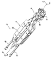
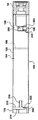
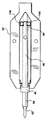
本発明の実施形態が、先ず、図1を参照して記載され、その図1は、全体的に10で指示されている射出成形機を示している。射出成形機は、12で指示されている型締ユニットを備えており、この型締ユニットは、14で指示されている射出ユニットと相互接続されており且つその射出ユニットに固定されている。 An embodiment of the present invention will first be described with reference to FIG. 1, which shows an injection molding machine indicated generally at 10. The injection molding machine is provided with a clamping unit indicated at 12, which is interconnected with and fixed to the injection unit indicated at 14.
固定盤16が、型締ユニット12の型締フレーム部材18に固定されている。可動盤20が、アクチュエータ22により、開放位置と閉鎖位置との間で作用し得る。アクチュエータ22は、液圧式アクチュエータ、電気式アクチュエータ、又は液圧式アクチュエータ及び電気式アクチュエータの組合せのいずれかであってよい、ということを、当業者は、認識しよう。複数のタイバー32が、固定盤16とアクチュエータ22との間を延びている。金型の可動半体24が、可動盤20の面上に装着されていると共に、金型の固定半体26が、固定盤16の面上に装着されている。
The
図1の型締ユニット12は、二定盤式型締機である。あるいは、型締ユニット12は、2つ以上の可動盤と2つ以上の金型とを有している、マルチステーション式型締ユニット(例えばスタック金型キャリア)であってもよい。あるいは、型締ユニット12は、回転マルチフェース・タレットブロックを可動盤の所定の場所に有しているインデックス式型締ユニットであってもよい。あるいは、型締ユニット12は、順次操作される2つの金型を有しているタンデム式型締ユニットであってもよい。
The
射出組立体27が、射出ユニット14の射出ユニットフレーム28上に装着されている。フレーム28は、典型的に、制御システム、電子機器、及びパワーパックを収容している。射出組立体27は、更に、バレル組立体30、このバレル組立体30を支持し且つ固定するキャリジ組立体34、及び駆動装置組立体36を含んでいる。駆動装置は、材料の溶融体を生成し且つ蓄積ゾーン内へとその材料をバレル内に供給すべく、スクリュを回転させる。駆動装置は、また、材料の溶融体を金型内へ射出すべく、スクリュを往復運動させる。
An
ここで図1及び図2を参照しつつ、駆動装置組立体36が、更に記載される。本発明の実施形態においては、駆動装置組立体は、液圧部品と電気部品との両方を含んでいる。スクリュ並進駆動装置38が、バレル組立体30内のスクリュ(図示せず)の軸方向運動をもたらす。スクリュ回転駆動装置40が、スクリュ(図示せず)をバレル組立体30内で回転させる。スクリュ並進駆動装置38は、液圧式であり、そして、スクリュ回転駆動装置40は、電気式である。あるいは、駆動装置は、完全に液圧式であってもよく又は完全に電気式であってもよい。並進駆動装置38の活性化は、スクリュ回転駆動装置40によるスクリュの回転を伴わないで、スクリュを軸方向に往復運動させる。
With reference now to FIGS. 1 and 2, the
バレル組立体30は、キャリジ組立体34内に装着され且つしっかりと保持されている。キャリジアクチュエータ42が、キャリジ組立体34と固定盤(図1参照)との間を延びている。キャリジアクチュエータ42の作動は、ノズルの端部をスプルーブッシュとの接触状態へと位置させるべく、射出組立体27を固定盤に向かう方向に且つその固定盤から離れる方向に移動させる。
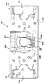
ここで図3を参照しつつ、射出組立体27が、更に記載される。キャリジ組立体34は、クレードル部材52と、ヨーク50と、駆動装置組立体36(図1及び図2参照)を装着するための駆動装置マウント54とを含んでいる。
With reference now to FIG. 3, the
バレル組立体30は、第1バレル部分44と、第1バレル連結部46と、第2バレル部分48と、第2バレル連結部60とを含んでいる。第1バレル連結部46は、バレル組立体30上に配置されていると共に、バレル組立体30をキャリジ組立体34内に固定すべく、第1キャリジ連結部と連動する。第1キャリジ連結部は、後述のように、ヨーク50とクレードル部材52の端部との中間に形成されている。
The
第1バレル連結部46の位置は、バレル組立体30の第1バレル部分44と第2バレル部分48との境界を定めている。第1バレル部分44は、射出成形圧に耐え得るバレルのセクションである。第2バレル部分48は、軸方向の力(軸方向キャリジ力及び軸方向射出反力の両方)から隔離されているバレルのセクションである。
The position of the first
第2連結部60は、第2バレル部分48上に配置されていると共に、バレル組立体30の第2バレル部分48をクレードル組立体34内に保持しつつ、駆動装置マウント54の近傍位置において、クレードル部材52の別の端部に位置させられている第2キャリジ連結部と連絡している。あるいは、第2連結部60は、第1バレル連結部46と第2バレル部分48の端部との間に配置されていてもよい。
The second connecting
キャリジアクチュエータ42は、1対の液圧式アクチュエータ(56及び58として指示されている)を含んでいる。第1キャリジアクチュエータ56の一方の端部は、開口51及び53を通るピン(図示せず)のような在来のファスナにより、キャリジ組立体34の一の側部に接続される。第1キャリジアクチュエータ56の他方の端部は、固定盤(図1参照)に接続する。第2キャリジアクチュエータ58の一方の端部は、開口55及び57を通るピン(図示せず)のような別の在来のファスナにより、キャリジ組立体34の第2の側部に接続される。第2キャリジアクチュエータ58の他方の端部は、固定盤(図示せず)に接続する。
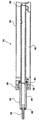
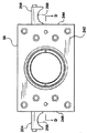
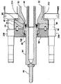
ここで図4を参照しつつ、バレル組立体30の断面図が、ここで更に説明される。キャリジ組立体34内に装着されているバレル組立体30が、示されている。バレル組立体34は、第1バレル部分44と、第2バレル部分48とを含んでいる。第1バレル連結部46は、バレル組立体30上に配置されていると共に、第1バレル部分と第2バレル部分との間の境界を定めている。第2バレル連結部60は、第2バレル部分48における端部に配置されている。この実施形態においては、第1バレル連結部46は、第1バレルセクション44上に一体に形成されていると共に、第2バレル連結部60は、第2バレル部分48の外面上へ形成されている。
Referring now to FIG. 4, a cross-sectional view of the
第1バレル部分44は、ノズル62と、アキュムレータ64とを含んでいる。ノズル62は、複数のファスナにより、アキュムレータ64の端部に機械的に固定されている。ノズル62は、溶融した材料の漏れを防ぐべく、アキュムレータ64の端部との接合部66において密封している。ノズル62の軸方向の内腔は、射出の間の溶融体の流れを可能にすべく、アキュムレータ64の軸方向の内腔と整合している。あるいは、ノズル62は、バレル組立体30との一体構造のものである。
The
第2バレル部分48は、供給セクションであると共に、複数のファスナにより、アキュムレータ64の別の端部に機械的に固定されている。第2バレル部分48は、アキュムレータ64のその別の端部における接合部68において密封している。第2バレル部分48の軸方向の内腔は、第2バレルセクション48からアキュムレータ64への溶融体の流れを可能にすべく、アキュムレータの軸方向の内腔と整合している。本発明の代替実施形態においては、第1バレルセクション44及び第2バレルセクション48は、接合部66及び68のない、一体構造のものである。
The
ここで図5及び図6を参照しつつ、ノズル62の2つの実施形態が、記載される。ノズル62は、装着フランジ72からノズル62の金型端部86まで延びている、細長い円筒状セクション70を有している。装着フランジ72は、円筒状であると共に、細長い円筒状セクション70と一体に形成されている。装着フランジ72は、細長いセクション70よりも大きい径を有している。装着フランジ72は、複数の離隔させられている内腔74であって、装着ボルト(図示せず)を受容するためのものを備えている。ノズル62のアキュムレータ端部76は、スピゴットシール部78を備えている。スピゴットシール部78は、円筒状であると共に、フランジ72の側部から外方に延出している。ノズル62は、第1の直径の軸方向内腔80と第1のコンセントレータ82と第2の直径の軸方向内腔84とによって作られている溶融体チャンネルを備えている。射出の間の作動中、溶融体チャンネルは、開口92を通してアキュムレータから溶融体を受容する。溶融体は、金型への途上で、ノズル62内の溶融体チャンネルに沿って移動し、別の開口94においてノズルを出て行く。
With reference now to FIGS. 5 and 6, two embodiments of the
ノズル62の第1実施形態においては、金型端部86は、スピゴット先端部88を備えている。スピゴット先端部88は、円筒状であると共に、材料の溶融体の射出の間におけるノズル64の金型端部86とスプルーブッシュ(図示せず)との間の密封係合用の、スプルーブッシュ内の相補的な円筒状の内腔内へ延入する。作動中、スピゴット先端部88は、スプルーブッシュ内の相補的な円筒状の内腔との摺動密封係合状態にある。スピゴット先端部88は、スプルーブッシュに対して移動することを許容される。
In the first embodiment of the
ノズル62の第2実施形態においては、金型端部86は、凸状の半球先端部90を備えている。半球先端部90は、材料の溶融体の射出の間におけるノズル64の金型端部86とスプルーブッシュ(図示せず)との間の密封係合用の、スプルーブッシュ内の相補的な凹状の半球開口と係合する。作動中、半球先端部90は、スプルーブッシュ内の相補的な凹状の半球開口との圧力密封係合状態にある。
In the second embodiment of the
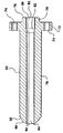
ここで図7及び図8を参照しつつ、64で全体的に指示されているアキュムレータセクションが、記載される。アキュムレータは、細長いセクション104と、第1バレル連結部46とを含んでいる。本発明の実施形態においては、連結部46は、96として指示されている軸方向力リンク部材と、98として指示されている断熱材とを備えている。あるいは、連結部46は、断熱材98と一体化されている軸方向力リンク部材96である、リンク絶縁体99を備えていてもよい。軸方向溶融体チャンネルが、アキュムレータ64を貫通して延びている。軸方向溶融体チャンネルは、第1の直径のアキュムレータ内腔112と、第2のコンセントレータ110と、第2の直径の内腔116とを備えている。第1の直径のアキュムレータ内腔112は、ノズル62の第1の直径の内腔80と整合し且つその内腔80と接続する。第2の直径の内腔116は、第2バレル部分48(図示せず)の軸方向内腔147と整合し且つその軸方向内腔147と接続する。第2の直径の内腔116(蓄積ゾーンを画成している)によって定められている容積が、金型内への射出に対して利用可能な最大ショットサイズを決定する。
With reference now to FIGS. 7 and 8, an accumulator section generally indicated at 64 is described. The accumulator includes an
アキュムレータ64は、実質的に円筒状であり、射出力及び射出反力に起因する高い圧力に耐えるべく、適切な肉厚(細長いセクション104の外面と溶融体チャンネルとの間)を備えている。本発明の実施形態においては、アキュムレータ64の肉厚は、軸方向キャリジ力にも耐えなければならない。
The
ノズル62は、このノズル62のフランジ72を介して、アキュムレータ64の端壁118に接続する。アキュムレータ64の端壁118は、複数の螺子穴108を備えている。ノズル62のフランジ72は、対応する複数の内腔74を備えている。ボルトが、内腔74と螺子穴108とを介して、ノズル62をアキュムレータ64に相互接続する。アキュムレータ64における内腔114は、ノズル62とアキュムレータ64との間の密封係合用の、ノズルのスピゴット78を緊密に受容する相補的な直径のものである。あるいは、ノズル62とアキュムレータ64との間の漏れを防止すべく、シールが、組み込まれてもよい。通常、ヒーターバンドが、アキュムレータ64の外面と、連結部46の側部126とに固定される。
The
本発明の実施形態においては、連結部46は、アキュムレータ64の端部に一体に形成されている。あるいは、連結部46は、アキュムレータ64に保持されている又は固定されている別体の部品であってもよい。例えば、連結部46は、アキュムレータ64の外面に溶接され得又はアキュムレータ64に螺着させられ得る。保持される又は固定される接続部は軸方向力に耐えるべく設計されなければならないということを、当業者は、認識しよう。
In the embodiment of the present invention, the connecting
本発明の実施形態においては、連結部46は、軸方向力リンク部材96を含んでいる。図示されている実施形態については、軸方向力リンク部材96は、1対の外方に延出している部材であり、これらの部材は、連結部46の第1端壁120上に一体に形成されている。あるいは、軸方向力リンク部材96は、複数の外方に延出している部材であっても、複数の支柱ポストであっても、又は連結部46と一体若しくは別体であり得る円筒状のリング部材であってもよい。本発明の別の実施形態においては、連結部46は、1対の軸方向力リンク部材(150,96、図21及び図23参照)であって、連結部46の第1端壁120及び第2端壁124上に配置されるものを含んでいる。
In the embodiment of the present invention, the connecting
連結部46の力リンク部材96の断面積は、要求されている軸方向力に耐えるようなものであるということを、当業者は、認識しよう。更に、軸方向力リンク部材96の位置は、均等で対称的な荷重分布をもたらすようなものである。
Those skilled in the art will recognize that the cross-sectional area of the
あるいは、連結部46は、第2の軸方向力リンク部材(又はリンク絶縁体)であって、連結部46の第2端壁124上に位置させられるものを含んでいてもよい。
Alternatively, the connecting
本発明の実施形態においては、軸方向力リンク部材96は、98で全体的に指示されている断熱材を備えている。図示されている実施形態については、断熱材98は、軸方向力リンク部材96の端部上に一体に形成されている。クレードル部材52内の第1キャリジ連結部(図示せず)との接触に関わるリンク部材96の断面積を最小にすることにより、作動中、断熱材は、熱いアキュムレータ64及び連結部46からクレードル部材52及びヨーク50への伝導性熱伝達を低減させる。あるいは、断熱材は、軸方向力リンク部材96と別体であってもよく、又は塗膜であってもよく、又は伝導性熱伝達を低減させる異なる材料であってもよい。断熱材は、第1バレル連結部46と第1キャリジ連結部との間の、接触している全ての面の中間に配置される。断熱材は要求されている軸方向力に耐えるようなものであるということを、当業者は、認識しよう。
In an embodiment of the present invention, the axial
ノズル62及びアキュムレータ64は、一緒になって、バレル組立体の第1バレル部分44を形成している。第1バレル部分44は、溶融体チャンネルを研磨性材料及び腐蝕性材料から保護するためのライナー又は保護塗膜を任意に備えている。
Together,
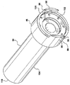
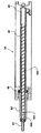
ここで図9及び図10を参照しつつ、第2バレル部分48が、記載される。示されている第2バレル部分48は、バレル組立体30の供給セクションであり、軸方向内腔147、第1開口146、第2開口134、及び供給スロート140を含んでいる。材料は、供給スロート140を通って第2部分48に入る。軸方向内腔128内に配置されるスクリュ(図示せず)が、アキュムレータ64に向けて、材料を軸方向内腔147内で運搬する。
With reference now to FIGS. 9 and 10, the
第2バレル部分48は、実質的に円筒状であり、供給材料の圧縮及び剪断に起因して発生する圧力に耐えるべく、適切な肉厚(細長いバレルの外面と、溶融体チャンネルとして作用する軸方向内腔147との間)を備えている。軸方向力は、第2バレル部分48を通るようには方向付けられていない。
The
第2バレル部分48は、バレルを研磨性材料及び腐蝕性材料から保護するためのライナー138であって、外側バレル142内に組み込まれているものを任意に備えている。
The
開口146は、スクリュ(図示せず)の軸方向内腔147内への組み込み及び軸方向内腔147内からの取り出しを可能にする。
The
第2部分48の第2端壁136は、フランジ130を介して、アキュムレータ64の連結部側に接続する。連結部46の端壁120は、複数の螺刻内腔102を備えている。第2部分48のフランジ130は、対応している複数の内腔132を備えている。ボルトが、内腔132と螺刻内腔102とを介して、第2部分48を連結部46に接続する。連結部46における内腔100は、連結部46と第2部分48との間の密封係合を行なうべく、第2部分48の円筒状接続部128を緊密に受容する相補的な直径のものである。連結部46における内腔122は、フランジ130を受容する相補的な直径のものである。あるいは、第1部分と第2部分48との間の漏れを防止すべく、シールが、組み込まれてもよい。アキュムレータ64の第2の直径の内腔116は、第2部分48の軸方向内腔147と軸方向に整合する。
The
第2バレル連結部60が、第2部分48の端部に形成されている。スクリュ(図示せず)の作業回転の間のバレル組立体30の回転運動を防止すべく、第2バレル連結部60は、クレードル係合部材との相補的な係合用の、153として指示されている、少なくとも1つの係合部材を含んでいる。通常、ヒーターバンドが、第2バレル部分48の外面に固定される。
A second
図示されている実施形態においては、係合部材153は、バレルの外面に機械加工された平坦な凹部である。あるいは、係合部材153は、外方に突出している部材であっても、溝であっても、若しくはスロットであってもよく、又はキー溝を切られてもよい。任意に、クレードル組立体から解放される際にバレル組立体が前方に傾くのを防止し且つ第2バレルセクションを駆動装置組立体と垂直方向に整合させる除去板(図示せず)と、別の凹部155が、係合する。
In the illustrated embodiment, the
射出成形機の用途であって、この用途においては、材料の溶融体がチキソトロープ状態にある金属(例えばマグネシウム)である、ものにおいては、ノズル62は、DIN2888又はDIN2999に基づいて作られ得る。アキュムレータ44及び第1バレル連結部68(軸方向力絶縁体を含む)は、ステライト(Stellite)12ライナーを備えた状態で、インコネル(Inconel)718で作られ得る。第2部分48も、ステライト12ライナーを備えた状態で、インコネル718で作られ得る。
In an injection molding machine application, where the material melt is a metal in a thixotropic state (eg magnesium), the
射出成形機の用途であって、この用途においては、材料の溶融体がプラスチックである、ものにおいては、ノズル62は、H13チップを備えた状態で、SAE4140で作られ得る。アキュムレータ64及び第1バレル連結部68(軸方向力絶縁体を含む)は、流し込ライナーを備えた状態で、4140で作られ得る。第2部分48は、流し込ライナーを備えた状態で、4140で作られ得る。
In an injection molding machine application where the material melt is plastic, the
ノズル62、アキュムレータ44、第1バレル連結部68及び第2部分48は、材料のビレットから機械加工され得、あるいは、それらは、熱等圧プレス(HIP)法によって形成され、次いで、機械加工され得る。
The
ここで図3及び図11を参照しつつ、キャリジ組立体34のクレードル部材52が、更に記載される。クレードル部材52は、図11の平面図に示されているように、実質的に矩形である。第1クレードル連結部178が、クレードル部材52の一の端部に形成されている。駆動装置マウント54が、クレードル部材52の第2の端部に形成されている。駆動装置マウント54は、軸方向内腔であって、バレル(図示せず)の軸方向内腔内に位置させられているスクリュの端部に駆動装置組立体を接続するためのものを備えている。第1クレードル連結部178及び駆動装置マウント54は、クレードル部材52の縦軸を中心として整合させられている。
With reference now to FIGS. 3 and 11, the
第1クレードル部材178及び駆動装置マウント54は、第1キャリジアクチュエータハウジング170と第2キャリジアクチュエータハウジング172とを介して、相互接続されている。
The
第1キャリジハウジング170は、第1キャリジアクチュエータ56を保持する、長さ方向のU字形矩形チャンネルを形成している。第1キャリジハウジング170は、支持ウエブ180を備えており、この支持ウエブ180は、第1キャリジハウジング170の端部の近くに位置させられていると共に、上側キャリジ部材182と下側キャリジ部材184との間を延在している。直立壁部材192が、上側キャリジ部材182と下側キャリジ部材184とを接続している。
The
第2キャリジハウジング172は、第2キャリジアクチュエータ58を保持する、第2の長さ方向のU字形矩形チャンネルを形成している。第2キャリジハウジング172は、支持ウエブ186を備えており、この支持ウエブ186は、第2キャリジハウジング172の端部の近くに位置させられていると共に、上側キャリジ部材188と下側キャリジ部材190との間を延在している。第2の直立壁部材194が、上側キャリジ部材188と下側キャリジ部材190とを接続している。
The
クレードル部材52は、長さ方向の軸方向開口部176を有しており、この軸方向開口部176は、クレードル部材52の第1端部174から駆動装置マウント54まで延びている。この開口部は、バレル組立体(図3参照)のクレードル部材52内への挿入及びクレードル部材52からの取り外し用の、開けた、障害物のないアクセス路を提供する。
The
ここで図11及び図12を参照しつつ、第1クレードル連結部178及び第2キャリジ連結部148が、更に記載される。
With reference now to FIGS. 11 and 12, the
クレードル部材52は、第2支持部206を備えており、この第2支持部206は、クレードル部材52の第1端部174において、直立壁部材(192,194)の間を延在している。本発明の実施形態においては、第1クレードル連結部148は、第1連結部材208と、第2連結部材210とを備えている。第1連結部材及び第2連結部材(208,210)は、直立壁部材(190,192)から外方に延出している。第1連結部材208は、第1連結面212を備えており、そして、第2連結部材210は、第2連結面214を備えている。第1クレードル連結部178は、第1バレル連結部46を受容するための、縦軸を中心とする開口を形成している。本発明の実施形態においては、第1連結面212及び第2連結面214は、バレル連結部60の軸方向力リンク部材96と係合する。あるいは、第1連結面212及び第2連結面214は、断熱材98と係合する。1対の支持ガセット216が、第1連結部材及び第2連結部材(208,210)の裏面と直立壁部材(192,194)との間を延在している。
The
クレードル部材52は、また、第1支持部196を備えており、この第1支持部196は、直立壁部材(192,194)と駆動装置マウント54との間を延在している。第1支持部196は、T字形である。本発明の実施形態においては、第2キャリジ連結部148は、第1連結部材198と、第2連結部材200とを備えている。第1連結部材及び第2連結部材(198,200)は、第1支持部196の上面から上方に且つ直立壁部材(192,194)から外方に延出している。第2キャリジ連結部148は、第2バレル連結部60を受容するための、縦軸を中心とする開口を形成している。第1連結面202及び第2連結面204が、第2バレル連結部60の相補的な面(153)と係合する。
The
第1バレル支持部材218が、第2支持部206の上面上に形成されている。第1バレル支持部材218は、第1直立支柱222と、第2直立支柱224とを備えている。第1バレル連結部46を第1クレードル連結部178に対して位置させるべく、支柱(222,224)は、第2支持部206の上面より上方の、バレル組立体30の外面と係合する高さのものである。
A first
第2バレル支持部材220が、第1支持部196の上面上に形成されている。第2バレル支持部材220は、第1直立支柱226と、第2直立支柱228とを備えている。第2バレル連結部60を第2キャリジ連結部148に対して位置させるべく、支柱(226,228)は、第1支持部196の上面より上方の、バレル組立体30の外面と係合する高さのものである。
A second barrel support member 220 is formed on the upper surface of the
第1バレル支持部材218及び第2バレル支持部材220は、バレル整合部材を形成し、バレル組立体30がクレードル部材34内に収容される際に、バレル組立体30を軸方向に整合させる。クレードル部材52は、追加のバレル支持部材を備えていてもよい。
The first
ここで図13を参照しつつ、クレードル部材52の第1端部174及び第1クレードル連結部178が、記載される。ヨーク装着面230が、第1キャリジハウジング170と第2キャリジハウジング172との間を延在している。ヨーク装着面230は、ヨーク50をクレードル部材52に固定するためのボルトを受容する、多数の螺刻内腔を備えている。第1直立支柱222及び第2直立支柱224は、バレル組立体30の外面をしっかりと支持すべき距離に離隔させられている。第1連結面212及び第2連結面214の断面積は、軸方向力に耐えるべく且つ軸方向力を第1バレル連結部46に分配すべく選択されている。第1バレル連結部46は、232として全体的に指示されているバレル連結部開口内へ嵌合する。
Referring now to FIG. 13, the
ここで図14を参照しつつ、クレードル部材52の駆動装置マウント54が、更に記載される。駆動装置マウント54は、駆動装置組立体36を装着する装着面234を備えている。駆動装置組立体36を駆動装置マウント54に装着するためのボルトを受容する、多数の螺刻内腔236が、設けられている。バレル内に装着されているスクリュ(図示せず)の端部に駆動装置組立体36を接続するための開口238が、設けられている。
With reference now to FIG. 14, the
ここで図15、図16及び図17を参照しつつ、ヨーク50が、更に記載される。ヨーク50は、矩形であり、前面240、後面242、左側部244、右側部246、頂部及び底部を有している。ヨーク50は、軸方向キャリジ力に耐える適切な厚さのものである。ヨーク50は、クレードル部材52のヨーク装着面230にヨーク50を固定するためのボルトを受容する、多数の開口248を備えている。中央軸方向内腔250は、バレル組立体30を受容するための第1直径と、バレル連結部46を受容するための第2直径とを有している。ヨーク50の連結面は、第2軸方向力リンク部材150と係合する。本発明の実施形態においては、連結面は、第1直径と第2直径との間に形成されているバレル座部252である。バレル座部252は、軸方向キャリジ力に耐えるべき且つ軸方向力を分配すべき断面積を有している。
The
本発明の実施形態においては、第1キャリジ連結部152は、ヨーク50とクレードル部材34の第1クレードル連結部178とによって形成されている。
In the embodiment of the present invention, the first
ヨーク50は、1対のヨーク支持部(254,258)を備えている。第1ヨーク支持部254は、ヨーク50の側部に装着されている。第2ヨーク支持部258は、第1ヨーク支持部254と向かい合って、ヨーク50の別の側部に装着されている。第1ヨーク支持部254は、支持面256を備えており、そして、第2ヨーク支持部258は、支持面260を備えている。支持面(256,260)は、キャリジ組立体34の組み立ての間にヨーク50を支持すべく、第1キャリジアクチュエータ56及び第2キャリジアクチュエータ58の相補的な面と係合する。
The
本発明の実施形態においては、ヨークは、プレート鋼A36であり、そして、クレードル組立体は、A536で鋳造されている。あるいは、クレードル組立体は、タイバーを介して相互接続されている1対の連結部であってもよい。 In an embodiment of the present invention, the yoke is plate steel A36 and the cradle assembly is cast at A536. Alternatively, the cradle assembly may be a pair of connections that are interconnected via tie bars.
本発明の代替実施形態においては、第1キャリジ連結部は、複数のタイバーを介して第2キャリジ連結部に相互接続される。本発明の別の代替実施形態においては、第1キャリジ連結部は、フレーム部材を介して第2キャリジ連結部に相互接続される。 In an alternative embodiment of the present invention, the first carriage link is interconnected to the second carriage link via a plurality of tie bars. In another alternative embodiment of the present invention, the first carriage link is interconnected to the second carriage link via a frame member.
キャリジ組立体52内へのバレル組立体30の組み込みが、図18及び図19を参照して記載される。射出ユニットフレーム28(図示せず)に対する射出組立体の軸方向運動用のクレードル部材52が、射出ユニット14のフレーム28上に装着される。キャリジアクチュエータ42が、クレードル部材52内に装着され、固定部材(例えば、射出成形機10の固定盤16)に接続される。キャリジアクチュエータ42は、クレードル部材52を固定盤16(図18参照)から離れる方向に移動させるべく作動させられる。ヨーク50が、クレードル部材52の第1端部174から離されて、キャリジアクチュエータ42上に置かれる。支持面256が、一方のアクチュエータと係合し、そして、支持面260が、他方のアクチュエータと係合する。
Incorporation of the
バレル組立体30が、クレードル部材34の開口部内へ下ろされる。第1バレル連結部46が、第1クレードル連結部178と整合させられる。第2バレル連結部60が、第2キャリジ連結部148と整合させられる。バレル組立体30が第1バレル支持部材218及び第2バレル支持部材200と係合するまで、バレル組立体30は、下ろされる。バレル支持部材(218,200)は、バレル組立体30をクレードル部材34内において整合させる。
バレル組立体30をクレードル部材52内に垂直方向に保持すべく、矩形の保持プレート262(図19参照)が、第2バレル連結部60の支持面155と係合する。プレート262は、在来のボルトにより、第1連結部材及び第2連結部材(200,198)に固定される。プレート262の下面が、キャリジ組立体34内でのバレル組立体30の軸方向運動を許容しつつ、支持面155と係合する。
In order to hold the
ヨーク50が、クレードル部材52の第1端部174に向かって移動させられ、多数のボルトにより、クレードル部材52の第1端部174に固定される。ヨーク50をクレードル部材34に整合させるための、多数の整合ピン及び整合開口が、ヨーク50とヨーク装着面230との間に設けられている。第1バレル連結部46が、キャリジ組立体に有効に固定され且つ締着される。次いで、往復スクリュ(バレル組立体の軸方向内腔内に位置させられている)が、駆動装置組立体36に接続される。
The
キャリジ組立体52からのバレル組立体30の取り出しは装着と逆の作業であるということを、当業者は、認識しよう。
Those skilled in the art will recognize that removal of the
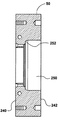
ここで図20を参照するに、キャリジ組立体34内に装着されているバレル組立体30及び第2バレル連結部60が、ヨーク50を伴わない平面図として示されている。
Referring now to FIG. 20, the
第2バレル連結部60は、バレル組立体30の第2バレル部分48をクレードル部材52に保持しつつ、第2キャリジ連結部148と係合する。第2バレル連結部60及び第2キャリジ連結部148は、スクリュ(図示せず)の回転動作の間にバレル組立体30が縦軸を中心として回転するのを防止する。第2バレル連結部60及び第2キャリジ連結部148は、第2バレル部分48を軸方向力から効果的に隔離しつつ、第2バレル部分の軸方向縦運動を可能にする。
The second
ここで図21を参照するに、キャリジ組立体34内に装着されているバレル組立体30の部分図が、図2のBB線に沿う部分断面図として示されている。
Referring now to FIG. 21, a partial view of the
バレル組立体30は、キャリジ組立体34内に収容され且つ固定されている。本発明の実施形態においては、断熱材及び第1軸方向力リンク部材96が、第1キャリジ連結部152の面と係合している。リング形状の第2軸方向力リンク部材150が、連結部46の他方の側部に位置させられている。第2軸方向力リンク部材150の断熱材の面が、ヨーク50の内面(バレル座部)と係合している。ヨーク50は、キャリジ組立体34の最前部に位置させられている。ヨーク50は、第1バレル連結部46をしっかりと締着すべく、キャリジ組立体34の前方セクションにボルト締めされている。
バレル組立体30をキャリジ組立体34に固定するための締付力が、ヨーク50とキャリジ組立体34との間に供給される。締付力は、第2軸方向力リンク部材150(断熱材を含む)、第1バレル連結部46、及び第1軸方向力リンク部材96(断熱材を含む)を通るように方向付けられている。
A clamping force for fixing the
作動時において、バレル連結部46を通るように軸方向キャリジ力が方向付けられるところの、2つの異なる場合が、存在する。ノズル62がスピゴット先端部88(図5参照)を備えている場合においては、ヨークは、第1キャリジストップ156及び第2キャリジストップ158(あるいは、単一のキャリジストップ)を備えている。第1キャリジストップ及び第2キャリジストップは、ボルトにより、ヨーク50の前面に装着されている。第1ストップ及び第2ストップは、固定盤の表面と係合すべく、ヨーク50の前面から外方に延出している。第1ストップ及び第2ストップの長さは、スピゴット先端部88がスプルーブッシュ内へ入るのを許容するようなものである。キャリジアクチュエータ42の作動は、第1ストップ及び第2ストップが固定盤16と係合して更なる前進運動を防止するまで、キャリジ組立体34とバレル組立体30とを固定盤16(図1参照)に向けて移動させる。キャリジアクチュエータ42は、軸方向キャリジ力を生成すべく、更に作動させられる。軸方向キャリジ力は、第1キャリジアクチュエータ56及び第2キャリジアクチュエータ58を通して、キャリジ組立体34に向けられる。キャリジ組立体34は、更に、第1キャリジ連結部152を通して、軸方向キャリジ力を、第1軸方向力リンク部材96、第1バレル連結部46、第2軸方向力リンク部材150、ヨーク50、並びに第1ストップ及び第2ストップへ向ける。これは、第2バレル部分48を軸方向力から隔離する。
In operation, there are two different cases where the axial carriage force is directed through the
ここで図22を参照しつつ、軸方向射出力が、記載される。射出段階の間、スクリュ並進駆動装置38が、バレル組立体30内においてスクリュを前方へ移動させるべく作動させられる。射出力が、並進駆動装置38から、往復スクリュ本体164へ、そして、往復スクリュの前に位置させられている材料の溶融体へ向けられる。アキュムレータ64を通して、射出反力が、第1バレル連結部46(リンク部材を含む)へ、第1クレードル連結部152へ、第1キャリジアクチュエータハウジング及び第2キャリジアクチュエータハウジング(170,172)へ、駆動装置マウント54へ、そして、スクリュ並進駆動装置組立体30へ向けられる。第2バレル部分は、軸方向射出反力から隔離されている。
With reference now to FIG. 22, the axial firing power is described. During the injection phase, the
ここで図23を参照するに、ノズル62が半球先端部90(図6参照)を備えている場合においては、第1ストップ156及び第2ストップ158は、必要ない。キャリジアクチュエータ42の作動は、半球先端部90がスプルーブッシュと係合するまで、キャリジ組立体34とバレル組立体30とを固定盤16に向けて移動させる。キャリジアクチュエータ42は、軸方向キャリジ力を生成すべく、更に作動させられる。軸方向キャリジ力は、第1キャリジアクチュエータ56と第2キャリジアクチュエータ58とを通して、キャリジ組立体34へ向けられる。キャリジ組立体34は、更に、第1キャリジ連結部152を通して、軸方向キャリジ力を、第1軸方向力リンク部材96、第1バレル連結部46、アキュムレータ64、及びノズル62へ向ける。第1バレル部分は、軸方向キャリジ力を分配し、そして、第2バレル部分は、軸方向キャリジ力から隔離されている。
Referring now to FIG. 23, the
ここで図24を参照しつつ、軸方向射出力が、記載される。射出段階の間、スクリュ並進駆動装置38は、バレル組立体30内でスクリュを前方へ移動させるべく作動させられる。射出力は、並進駆動装置38から、往復スクリュ本体164へ、そして、往復スクリュの前に位置させられている材料の溶融体へ向けられる。アキュムレータ64を通して、第1射出反力が、第1バレル連結部46(リンク部材を含む)へ、第1クレードル連結部152へ、第1キャリジアクチュエータハウジング及び第2キャリジアクチュエータハウジング(170,172)へ、駆動装置マウント54へ、そして、スクリュ並進駆動装置組立体30へ向けられる。ノズル62を通して、第2射出反力が、アキュムレータ64へ、第1バレル連結部46(リンク部材を含む)へ、第1クレードル連結部152へ、第1キャリジアクチュエータハウジング及び第2キャリジアクチュエータハウジング(170,172)へ、駆動装置マウント54へ、そして、スクリュ並進駆動装置組立体30へ向けられる。第2バレル部分は、軸方向射出反力から隔離されている。
With reference now to FIG. 24, the axial firing force is described. During the injection phase, the
ここで図25及び図26を参照しつつ、バレル組立体内でのスクリュの動作が、記載される。ノズル62、アキュムレータ64、第1バレル連結部46、第2バレル部分48、及び第2バレル連結部60を含む、バレル組立体は、前述のように、それぞれ、キャリジ組立体34内に固定され且つ保持されている。スクリュは、アキュムレータ及び第2バレル部分の軸方向内腔内に位置させられている。スクリュは、スクリュ先端部160と、逆止弁162と、往復スクリュ本体164とを含んでいる。スクリュは、射出位置(図13参照)と最大ショット位置(図14参照)との間を往復運動可能である。
With reference now to FIGS. 25 and 26, the operation of the screw within the barrel assembly will be described. The barrel assemblies, including
作動時において、スクリュは、射出位置で始動する。供給材料が、供給ポートを通って、バレル組立体の軸方向内腔に入る。材料は、溶融され、スクリュ本体164に沿ってスクリュ先端部160に向けて前方へ運搬される。材料のショットがアキュムレータ64の蓄積ゾーン内のスクリュ先端部160の前に徐々に現れると、適切なショット量が蓄積ゾーン内に受容されるまで、スクリュは、後方に移動する。次いで、スクリュは、溶融体のショットを金型内へ射出しつつ、前方へ進ませられる。逆止弁162は、溶融体が逆止弁の前方に移動するのは許容するが、逆止弁の後方に移動するのは許容しない。作動中、逆止弁は、アキュムレータ64の軸方向内腔内でのみ往復運動する。
In operation, the screw starts in the injection position. Feed material enters the axial lumen of the barrel assembly through the feed port. The material is melted and conveyed forward along the
本発明の実施形態においては、バレル組立体は、単一の一体構造で形成されている。別の実施形態においては、バレル組立体は、第2セクションに接続されている第1セクションである。別の実施形態においては、第1セクションは、アキュムレータに接続されているノズルである。別の実施形態においては、第1セクションは、バレルヘッドに接続されているノズルであり、そのバレルヘッドは、アキュムレータに接続されている。 In an embodiment of the present invention, the barrel assembly is formed as a single unitary structure. In another embodiment, the barrel assembly is a first section connected to a second section. In another embodiment, the first section is a nozzle connected to an accumulator. In another embodiment, the first section is a nozzle connected to a barrel head that is connected to an accumulator.
本発明は、本明細書に記載されている説明に限定されず、それらの説明は、本発明を実施する最良のモードを説明するためのものであると見なされ、そして、それらの説明は、部品の形態、サイズ、構成の変更、及び動作の詳細の変更を受容可能である、ということが、当業者によって理解されるべきである。本発明は、全てのそのような変更であって、請求項によって規定されている本発明の精神及び範囲内のものを包含すべく意図されている。 The present invention is not limited to the description set forth herein, which description is to be construed as illustrating the best mode of carrying out the invention, and the description is It should be understood by those skilled in the art that changes in part form, size, configuration, and operational details are acceptable. The present invention is intended to embrace all such modifications as fall within the spirit and scope of the invention as defined by the claims.
10 射出成形機
12 型締ユニット
14 射出ユニット
16 固定盤
18 型締フレーム部材
20 可動盤
22 アクチュエータ
24 金型の可動半体
26 金型の固定半体
27 射出組立体
28 射出ユニットフレーム
30 バレル組立体
32 タイバー
34 キャリジ組立体
36 駆動装置組立体
38 スクリュ並進駆動装置
40 スクリュ回転駆動装置
42 キャリジアクチュエータ
44 第1バレル部分
46 第1バレル連結部
48 第2バレル部分
50 ヨーク
51 開口
52 クレードル部材
53 開口
54 駆動装置マウント
55 開口
56 第1キャリジアクチュエータ
57 開口
58 第2キャリジアクチュエータ
60 第2バレル連結部
62 ノズル
64 アキュムレータ
66 密封接合部
68 密封接合部
70 細長いセクション
72 装着フランジ
74 内腔
76 アキュムレータ端部
78 スピゴット
80 第1の直径の軸方向内腔
82 第1のコンセントレータ
84 ノズルの第2の直径の軸方向内腔
86 金型端部
88 スピゴット先端部
90 半球先端部
92 開口
94 開口
96 軸方向力リンク部材
98 断熱材
99 リンク絶縁体
100 内腔
102 螺刻内腔
104 細長いセクション
108 螺刻内腔
110 第2のコンセントレータ
112 第1の直径のアキュムレータ内腔
114 内腔
116 第2の直径の内腔
118 端壁
120 第1端壁
122 内腔
124 第2端壁
126 側部
128 円筒状接続部
130 フランジ
132 内腔
134 第2開口
136 第2端壁
138 ライナー
140 供給スロート
142 外側バレル
146 第1開口
147 軸方向内腔
148 第2キャリジ連結部
150 第2軸方向力リンク部材
152 第1キャリジ連結部
153 係合部材
155 支持面
156 第1キャリジストップ
158 第2キャリジストップ
160 スクリュ先端部
162 逆止弁
164 往復スクリュ本体
170 第1キャリジアクチュエータハウジング
172 第2キャリジアクチュエータハウジング
174 第1端部
176 長さ方向の軸方向開口部
178 第1クレードル連結部
180 支持ウエブ
182 上側キャリジ部材
184 下側キャリジ部材
186 支持ウエブ
188 上側キャリジ部材
190 下側キャリジ部材
192 直立壁部材
194 直立壁部材
196 第1支持部
198 第1連結部材
200 第2連結部材
202 第1連結面
204 第2連結面
206 第2支持部
208 第1連結部材
210 第2連結部材
212 第1連結面
214 第2連結面
216 支持ガセット
218 第1バレル支持部材
220 第2バレル支持部材
222 第1直立支柱
224 第2直立支柱
226 第1直立支柱
228 第2直立支柱
230 ヨーク装着面
232 第1バレル連結部開口
234 装着面
236 螺刻内腔
238 開口
240 前面
242 後面
244 左側部
246 右側部
248 開口
250 中央軸方向内腔
252 バレル座部
254 第1ヨーク支持部
256 支持面
258 第2ヨーク支持部
260 支持面
262 保持プレート
DESCRIPTION OF SYMBOLS 10 Injection molding machine 12 Clamping unit 14 Injection unit 16 Fixed platen 18 Mold clamping frame member 20 Movable platen 22 Actuator 24 Mold movable half 26 Mold fixed half 27 Injection assembly 28 Injection unit frame 30 Barrel assembly 32 Tie bar 34 Carriage assembly 36 Drive assembly 38 Screw translation drive 40 Screw rotation drive 42 Carriage actuator 44 First barrel portion 46 First barrel connecting portion 48 Second barrel portion 50 Yoke 51 Opening 52 Cradle member 53 Opening 54 Drive device mount 55 Opening 56 First carriage actuator 57 Opening 58 Second carriage actuator 60 Second barrel connecting part 62 Nozzle 64 Accumulator 66 Sealing joint 68 Sealing joint 70 Elongated section 72 Mounting flange 74 Lumen 76 Aki Murator end 78 Spigot 80 First diameter axial lumen 82 First concentrator 84 Nozzle second diameter axial lumen 86 Mold end 88 Spigot tip 90 Hemispherical tip 92 Opening 94 Opening 96 Axial force link member 98 Insulation 99 Link insulator 100 Lumen 102 Threaded lumen 104 Elongated section 108 Threaded lumen 110 Second concentrator 112 First diameter accumulator lumen 114 Lumen 116 Second diameter Lumen 118 end wall 120 first end wall 122 lumen 124 second end wall 126 side 128 cylindrical connection 130 flange 132 lumen 134 second opening 136 second end wall 138 liner 140 supply throat 142 outer barrel 146 First opening 147 Axial lumen 148 Second carriage connection 150 Second axial force link member 15 First carriage connecting portion 153 Engaging member 155 Support surface 156 First carriage stop 158 Second carriage stop 160 Screw tip 162 Check valve 164 Reciprocating screw body 170 First carriage actuator housing 172 Second carriage actuator housing 174 First end Portion 176 Longitudinal axial opening 178 First cradle connecting portion 180 Support web 182 Upper carriage member 184 Lower carriage member 186 Support web 188 Upper carriage member 190 Lower carriage member 192 Upright wall member 194 Upright wall member 196 First 1 support part 198 1st connection member 200 2nd connection member 202 1st connection surface 204 2nd connection surface 206 2nd support part 208 1st connection member 210 2nd connection member 212 1st connection surface 214 2nd connection surface 216 support Gusset 21 8 First barrel support member 220 Second barrel support member 222 First upright column 224 Second upright column 226 First upright column 228 Second upright column 230 Yoke mounting surface 232 First barrel connecting part opening 234 Mounting surface 236 Cavity 238 Opening 240 Front 242 Rear 244 Left side 246 Right side 248 Opening 250 Central axial lumen 252 Barrel seat 254 First yoke support 256 Support surface 258 Second yoke support 260 Support surface 262 Holding plate
Claims (51)
バレル組立体(30)と、
キャリジ組立体(34)と、
を具備しており、
バレル組立体(30)は、第1バレル部分(44)及び第2バレル部分(48)であって、これらを貫通する軸方向内腔を有しているものと、第1バレル連結部(46)とを含んでおり、第1バレル連結部(46)の位置が、第1バレル部分(44)と第2バレル部分(48)との間の境界を定めており、
キャリジ組立体(34)は、第1バレル連結部(46)と係合する第1キャリジ連結部(152)を含んでおり、
キャリジ組立体(34)は、型締ユニット(12)の固定盤と結合するキャリジアクチュエータ(42)と協働すべく構成されており、
バレル組立体(30)及びキャリジ組立体(34)は、射出ユニットのフレーム上に装着されるべく構成されており、
キャリジ組立体(34)は、バレル組立体(30)の軸方向内腔内に配置され得るスクリュを作動させる駆動装置組立体(36)を受容すべく構成されており、
ここで、使用時において、第1バレル連結部(46)が、バレル組立体(30)をキャリジ組立体(34)内に固定すべく、第1キャリジ連結部(152)と連動し、これにより、第2バレル部分(48)が、軸方向キャリジ力から隔離され、
バレル組立体(30)及びキャリジ組立体(34)が、射出ユニットのフレーム上に装着されており、且つ、射出組立体が、更に、駆動装置組立体(36)を具備しており、この駆動装置組立体は、使用時において、バレル組立体(30)の軸方向内腔内に配置されているスクリュを作動させる、
射出組立体。 An injection assembly,
A barrel assembly (30);
A carriage assembly (34);
It has
The barrel assembly (30) includes a first barrel portion (44) and a second barrel portion (48) having an axial bore therethrough, and a first barrel coupling portion (46). ), And the position of the first barrel coupling portion (46) defines a boundary between the first barrel portion (44) and the second barrel portion (48),
The carriage assembly (34) includes a first carriage connection ( 152 ) that engages the first barrel connection (46) .
The carriage assembly (34) is configured to cooperate with a carriage actuator (42) coupled to the stationary platen of the clamping unit (12).
The barrel assembly (30) and carriage assembly (34) are configured to be mounted on the frame of the injection unit,
The carriage assembly (34) is configured to receive a drive assembly (36) that operates a screw that may be disposed within the axial lumen of the barrel assembly (30);
Here, in use, the first barrel connecting portion (46) is interlocked with the first carriage connecting portion (152) to fix the barrel assembly (30) in the carriage assembly (34), thereby The second barrel portion (48) is isolated from the axial carriage force ;
A barrel assembly (30) and a carriage assembly (34) are mounted on the frame of the injection unit, and the injection assembly further comprises a drive assembly (36). The device assembly, in use, operates a screw disposed within the axial lumen of the barrel assembly (30).
Injection assembly.
Applications Claiming Priority (2)
| Application Number | Priority Date | Filing Date | Title |
|---|---|---|---|
| US09/791,374 US6520762B2 (en) | 2001-02-23 | 2001-02-23 | Injection unit |
| PCT/CA2001/001634 WO2002066183A1 (en) | 2001-02-23 | 2001-11-21 | Injection unit |
Publications (2)
| Publication Number | Publication Date |
|---|---|
| JP2004522586A JP2004522586A (en) | 2004-07-29 |
| JP3799331B2 true JP3799331B2 (en) | 2006-07-19 |
Family
ID=25153540
Family Applications (1)
| Application Number | Title | Priority Date | Filing Date |
|---|---|---|---|
| JP2002565732A Expired - Fee Related JP3799331B2 (en) | 2001-02-23 | 2001-11-21 | Injection unit |
Country Status (17)
| Country | Link |
|---|---|
| US (1) | US6520762B2 (en) |
| EP (1) | EP1363753B1 (en) |
| JP (1) | JP3799331B2 (en) |
| KR (1) | KR100510231B1 (en) |
| CN (1) | CN1243621C (en) |
| AT (1) | ATE288334T1 (en) |
| AU (1) | AU2002220399B2 (en) |
| BR (1) | BR0116907B1 (en) |
| CA (1) | CA2436014C (en) |
| DE (1) | DE60108790T2 (en) |
| ES (1) | ES2236139T3 (en) |
| IL (2) | IL156886A0 (en) |
| MX (1) | MXPA03007593A (en) |
| PT (1) | PT1363753E (en) |
| RU (1) | RU2268807C2 (en) |
| TW (1) | TW550156B (en) |
| WO (1) | WO2002066183A1 (en) |
Families Citing this family (15)
| Publication number | Priority date | Publication date | Assignee | Title |
|---|---|---|---|---|
| US6918427B2 (en) * | 2003-03-04 | 2005-07-19 | Idraprince, Inc. | Process and apparatus for preparing a metal alloy |
| US7353858B2 (en) * | 2006-05-17 | 2008-04-08 | Husky Injection Molding Systems Ltd. | Cap for servicing molding-system valve |
| US7753671B2 (en) | 2007-02-21 | 2010-07-13 | Husky Injection Molding Systems Ltd. | Mechanical fuse assembly of molding system |
| US20090025901A1 (en) * | 2007-07-25 | 2009-01-29 | Husky Injection Molding Systems Ltd. | Molding System with Barrel Assembly |
| US20090028984A1 (en) * | 2007-07-26 | 2009-01-29 | Husky Injection Molding Systems Ltd. | Transition Channel For Use Between A First Conduit And A Second Conduit In A Molding System |
| US20090107646A1 (en) | 2007-10-31 | 2009-04-30 | Husky Injection Molding Systems Ltd. | Metal-Molding Conduit Assembly of Metal-Molding System |
| KR101149358B1 (en) * | 2008-11-18 | 2012-05-30 | 금호석유화학 주식회사 | An Apparatus for Compositing conducting composites and method thereof. |
| JP2014054643A (en) * | 2012-09-11 | 2014-03-27 | Ube Machinery Corporation Ltd | Injection device of die cast machine |
| WO2014202784A1 (en) | 2013-06-21 | 2014-12-24 | Fraunhofer-Gesellschaft zur Förderung der angewandten Forschung e.V. | Apparatus and method for improved signal fade out for switched audio coding systems during error concealment |
| CN103568207B (en) * | 2013-10-23 | 2015-08-26 | 浙江大学 | A kind of injection moulding machine barrel mounting structure |
| CN105537559A (en) * | 2016-01-28 | 2016-05-04 | 安徽鑫磊压铸机制造有限公司 | Automatic demolding mechanism of pressure casting machine |
| KR102429140B1 (en) * | 2016-08-09 | 2022-08-03 | 엘에스엠트론 주식회사 | Injection Molding Apparatus |
| AT518638B1 (en) * | 2016-09-23 | 2017-12-15 | Engel Austria Gmbh | Injection unit for a molding machine |
| AT521217B1 (en) * | 2018-05-11 | 2021-02-15 | Thixotropic Piston Injection Tech Gmbh | Module for a die casting device |
| CA3110120A1 (en) | 2018-08-30 | 2020-03-05 | Husky Injection Molding Systems Ltd. | Plastic molding apparatus and method with shaper module |
Family Cites Families (8)
| Publication number | Priority date | Publication date | Assignee | Title |
|---|---|---|---|---|
| GB1297783A (en) * | 1969-03-13 | 1972-11-29 | ||
| JPS5918724A (en) | 1982-07-23 | 1984-01-31 | Nitto Electric Ind Co Ltd | Termosetting resin composition |
| JPS59187824A (en) * | 1983-04-08 | 1984-10-25 | Yamashiro Seiki Seisakusho:Kk | Injection molding machine |
| DE3683181D1 (en) * | 1985-04-15 | 1992-02-13 | Karl Hehl | INJECTION MOLDING MACHINE FOR PLASTICS. |
| DE3742403C1 (en) * | 1987-12-15 | 1989-05-24 | Karl Hehl | Plasticizing unit with reinforcement skeleton for a plastic injection molding unit |
| US5040589A (en) | 1989-02-10 | 1991-08-20 | The Dow Chemical Company | Method and apparatus for the injection molding of metal alloys |
| US5983978A (en) | 1997-09-30 | 1999-11-16 | Thixomat, Inc. | Thermal shock resistant apparatus for molding thixotropic materials |
| US6077064A (en) | 1998-09-29 | 2000-06-20 | Husky Injection Molding Systems Ltd. | Injection molding apparatus and method for mounting same |
-
2001
- 2001-02-23 US US09/791,374 patent/US6520762B2/en not_active Expired - Fee Related
- 2001-11-21 IL IL15688601A patent/IL156886A0/en active IP Right Grant
- 2001-11-21 MX MXPA03007593A patent/MXPA03007593A/en active IP Right Grant
- 2001-11-21 ES ES01273763T patent/ES2236139T3/en not_active Expired - Lifetime
- 2001-11-21 EP EP01273763A patent/EP1363753B1/en not_active Expired - Lifetime
- 2001-11-21 RU RU2003128415/02A patent/RU2268807C2/en not_active IP Right Cessation
- 2001-11-21 KR KR10-2003-7011075A patent/KR100510231B1/en not_active Expired - Fee Related
- 2001-11-21 CN CNB018227805A patent/CN1243621C/en not_active Expired - Fee Related
- 2001-11-21 AT AT01273763T patent/ATE288334T1/en not_active IP Right Cessation
- 2001-11-21 BR BRPI0116907-6A patent/BR0116907B1/en not_active IP Right Cessation
- 2001-11-21 CA CA002436014A patent/CA2436014C/en not_active Expired - Fee Related
- 2001-11-21 WO PCT/CA2001/001634 patent/WO2002066183A1/en not_active Ceased
- 2001-11-21 PT PT01273763T patent/PT1363753E/en unknown
- 2001-11-21 JP JP2002565732A patent/JP3799331B2/en not_active Expired - Fee Related
- 2001-11-21 DE DE60108790T patent/DE60108790T2/en not_active Expired - Lifetime
- 2001-11-21 AU AU2002220399A patent/AU2002220399B2/en not_active Ceased
- 2001-11-30 TW TW090129659A patent/TW550156B/en not_active IP Right Cessation
-
2003
- 2003-07-10 IL IL156886A patent/IL156886A/en not_active IP Right Cessation
Also Published As
| Publication number | Publication date |
|---|---|
| KR100510231B1 (en) | 2005-08-26 |
| EP1363753B1 (en) | 2005-02-02 |
| IL156886A0 (en) | 2004-02-08 |
| AU2002220399B2 (en) | 2006-02-02 |
| BR0116907A (en) | 2004-02-10 |
| DE60108790D1 (en) | 2005-03-10 |
| CN1491142A (en) | 2004-04-21 |
| US6520762B2 (en) | 2003-02-18 |
| TW550156B (en) | 2003-09-01 |
| PT1363753E (en) | 2005-06-30 |
| DE60108790T2 (en) | 2006-03-30 |
| ATE288334T1 (en) | 2005-02-15 |
| IL156886A (en) | 2008-06-05 |
| RU2003128415A (en) | 2005-03-27 |
| JP2004522586A (en) | 2004-07-29 |
| US20020119212A1 (en) | 2002-08-29 |
| CA2436014C (en) | 2007-04-17 |
| KR20030080026A (en) | 2003-10-10 |
| RU2268807C2 (en) | 2006-01-27 |
| CN1243621C (en) | 2006-03-01 |
| HK1061821A1 (en) | 2004-10-08 |
| EP1363753A1 (en) | 2003-11-26 |
| ES2236139T3 (en) | 2005-07-16 |
| MXPA03007593A (en) | 2003-12-11 |
| WO2002066183A1 (en) | 2002-08-29 |
| BR0116907B1 (en) | 2009-01-13 |
| CA2436014A1 (en) | 2002-08-29 |
Similar Documents
| Publication | Publication Date | Title |
|---|---|---|
| JP4219684B2 (en) | Barrel assembly | |
| JP3799331B2 (en) | Injection unit | |
| AU2002221377A1 (en) | Barrel assembly | |
| CA2561515C (en) | Method and apparatus for coupling melt conduits in a molding system and/or a runner system | |
| AU2002220399A1 (en) | Injection unit | |
| US20020119213A1 (en) | Force isolating cradle | |
| US20020150646A1 (en) | Cradle for a quick barrel change | |
| HK1061822B (en) | Barrel assembly of an injection molding machine | |
| HK1061821B (en) | Injection unit | |
| JP4059786B2 (en) | Molten metal sealing device |
Legal Events
| Date | Code | Title | Description |
|---|---|---|---|
| A977 | Report on retrieval |
Free format text: JAPANESE INTERMEDIATE CODE: A971007 Effective date: 20050215 |
|
| A131 | Notification of reasons for refusal |
Free format text: JAPANESE INTERMEDIATE CODE: A131 Effective date: 20050413 |
|
| A521 | Request for written amendment filed |
Free format text: JAPANESE INTERMEDIATE CODE: A523 Effective date: 20050713 |
|
| TRDD | Decision of grant or rejection written | ||
| A01 | Written decision to grant a patent or to grant a registration (utility model) |
Free format text: JAPANESE INTERMEDIATE CODE: A01 Effective date: 20060403 |
|
| A61 | First payment of annual fees (during grant procedure) |
Free format text: JAPANESE INTERMEDIATE CODE: A61 Effective date: 20060424 |
|
| R150 | Certificate of patent or registration of utility model |
Free format text: JAPANESE INTERMEDIATE CODE: R150 |
|
| FPAY | Renewal fee payment (event date is renewal date of database) |
Free format text: PAYMENT UNTIL: 20100428 Year of fee payment: 4 |
|
| FPAY | Renewal fee payment (event date is renewal date of database) |
Free format text: PAYMENT UNTIL: 20110428 Year of fee payment: 5 |
|
| FPAY | Renewal fee payment (event date is renewal date of database) |
Free format text: PAYMENT UNTIL: 20120428 Year of fee payment: 6 |
|
| FPAY | Renewal fee payment (event date is renewal date of database) |
Free format text: PAYMENT UNTIL: 20130428 Year of fee payment: 7 |
|
| FPAY | Renewal fee payment (event date is renewal date of database) |
Free format text: PAYMENT UNTIL: 20140428 Year of fee payment: 8 |
|
| LAPS | Cancellation because of no payment of annual fees |