JP3798309B2 - Thermoforming apparatus and thermoforming method - Google Patents
Thermoforming apparatus and thermoforming method Download PDFInfo
- Publication number
- JP3798309B2 JP3798309B2 JP2001380195A JP2001380195A JP3798309B2 JP 3798309 B2 JP3798309 B2 JP 3798309B2 JP 2001380195 A JP2001380195 A JP 2001380195A JP 2001380195 A JP2001380195 A JP 2001380195A JP 3798309 B2 JP3798309 B2 JP 3798309B2
- Authority
- JP
- Japan
- Prior art keywords
- resin sheet
- heating plate
- female
- thermoforming
- alignment
- Prior art date
- Legal status (The legal status is an assumption and is not a legal conclusion. Google has not performed a legal analysis and makes no representation as to the accuracy of the status listed.)
- Expired - Lifetime
Links
Images


Landscapes
- Blow-Moulding Or Thermoforming Of Plastics Or The Like (AREA)
- Moulds For Moulding Plastics Or The Like (AREA)
Description
【0001】
【発明の属する技術分野】
本発明は、熱成形装置および熱成形方法に関し、特に、所定の模様が印刷された樹脂シートを同模様に対応して成形する熱成形装置および熱成形方法に関する。
【0002】
【従来の技術】
従来、この種の熱成形装置は、クランプ枠に樹脂シートをクランプしている。そして、樹脂シートがクランプされたクランプ枠を搬送機構によって成形機構に搬送する。この搬送機構は、ボールネジにて構成されており、上述したクランプ枠はこのボールネジに嵌合されている。そして、搬送機構は搬送に際して、このボールネジを回転動作させる。すると、ボールネジに嵌合されたクランプ枠はこの回転動作に応じて成形機構に搬出入される。すなわち、成形機構に配置された雌型の型面に対する樹脂シートの位置決めは、このボールネジによるクランプ枠の搬入移動によって行なわれている。
【0003】
【発明が解決しようとする課題】
上述した従来の熱成形装置において、成形機構に配置された雌型の型面に対する樹脂シートの位置合わせ精度はボールネジのネジピッチに依存することになる。このため、例えば、樹脂シートに所定の模様が印刷されている場合であって、この模様を型面に対して位置合わせする場合、このネジピッチ以上の位置合わせ精度を実現することができないという課題があった。
【0004】
本発明は、上記課題にかんがみてなされたもので、樹脂シートに印刷された模様を雌型の型面に対して正確に位置合わせすることが可能な熱成形装置および熱成形方法の提供を目的とする。
【0005】
【課題を解決するための手段】
上記目的を達成するため、請求項1にかかる発明は、所定の模様が印刷された樹脂シートを熱成形して同模様に対応した成形品を形成する熱成形装置であって、上記樹脂シートを加熱軟化させる加熱板と、上記模様に対応した型面を有する雌型と、上記雌型の上記加熱板との当接側に同加熱板方向に立設されるとともに、同加熱板と同雌型とが当接した際に同加熱板の内部と同雌型の内部とのいずれかに収容される突起部を有し、同突起部を上記樹脂シートに形成された凹形状の基準マークと嵌合させることにより、同樹脂シートに印刷された模様を上記型面に対して位置合わせする位置合わせ機構と、上記位置合わせ機構にて位置合わせされた樹脂シートに上記加熱板と上記雌型とを当接させて同樹脂シートを加熱軟化させつつ上記成形品を形成する成形機構とを具備する構成としてある。
【0006】
上記のように構成した請求項1にかかる発明においては、所定の模様が印刷された樹脂シートを熱成形して同模様に対応した成形品を形成する熱成形装置を提供するに際して、位置合わせ機構にて、雌型の加熱板との当接側に同加熱板方向に立設され加熱板と雌型とが当接した際に加熱板の内部と雌型の内部とのいずれかに収容される突起部を、上記樹脂シートに形成された凹形状の基準マークと嵌合させることにより、同樹脂シートに印刷された模様を雌型の型面に位置合わせする。そして、成形機構では、位置合わせ機構にて位置合わせされた樹脂シートに対して加熱板と雌型とを当接させることによって樹脂シートを加熱軟化させつつ成形品を形成する。このように位置合わせすることにより、模様が正確に反映された成形品を形成することが可能になる。
【0008】
熱成形に際して、雌型に立設された突起部が雌型と加熱板との当接面に合わせて陥没すると、同雌型および加熱板が当接面にて密着することが可能となり、雌型と加熱板とにて形成される空間の気密性を向上させることができて好適である。そこで、上記突起部は、加熱板と雌型とが当接した際に同雌型の内部に収容されるか、あるいは、加熱板と雌型とが当接した際に同加熱板に収容される。
熱成形に際して加熱板と雌型とが当接した場合、突起部を雌型の内部に収容されるように当該雌型を形成する。
【0009】
あるいは、熱成形に際して加熱板と雌型とが当接した場合、突起部が加熱板に収容されるように当該加熱板を形成する。
【0010】
熱成形に際しては、成形機構にて雌型と加熱板とが当接される。雌型においては上述したように位置合わせ機構にて樹脂シートと型面との位置合わせを行なう必要がある。この位置合わせに際して、作業者は雌型と加熱板との間にて作業を行なわなければならず煩雑である。そこで、請求項2にかかる発明は、請求項1に記載の熱成形装置において、上記成形機構に対して上記雌型を搬出入可能な搬送機構を備える構成としてある。
上記のように構成した請求項2にかかる発明においては、搬送機構にて雌型を成形機構に対して搬出入可能にする。これにより、作業者は雌型の型面に対して樹脂シートの位置合わせを行なってから搬送機構にて成形機構に搬入させれば良いため作業効率が良くなる。
【0011】
雌型と加熱板との位置関係は特に限定されるものではなく、熱成形に際して、当接させることができれば良い。ここで、当該雌型と加熱板との位置関係の一例として、請求項3にかかる発明は、請求項1または請求項2のいずれかに記載の熱成形装置において、上記加熱板は、上記雌型の上方側に配設される構成としてある。
上記のように構成した請求項3にかかる発明においては、加熱板を雌型の上方側に配設する。ここで、熱成形にて加熱板と雌型とを当接させるに際しては、加熱板を雌型に対して下降移動させても良いし、雌型を加熱板に対して上昇移動させても良い。むろん、加熱板と雌型とを相互に移動させるようにしても良い。
【0012】
雌型と加熱板との位置関係の他の一例として、請求項4にかかる発明は、請求項1または請求項2のいずれかに記載の熱成形装置において、上記加熱板は、上記雌型の下方側に配設される構成としてある。
上記のように構成した請求項4にかかる発明においては、加熱板を雌型の下方側に配設する。ここで、熱成形にて加熱板と雌型とを当接させるに際しては、上述と同様に加熱板を雌型に対して下降移動させても良いし、雌型を加熱板に対して上昇移動させても良い。むろん、加熱板と雌型とを相互に移動させるようにしても良い。
【0013】
位置合わせ機構にて位置合わせした際に、位置合わせ後の樹脂シートが雌型に対して固定されると好適である。そこで、請求項5にかかる発明は、請求項1〜請求項4のいずれかに記載の熱成形装置において、上記樹脂シートの基準マークの凹形状は、貫通孔に形成されるとともに、上記位置合わせ機構は、この貫通孔に上記突起部を挿入させることにより上記位置合わせを行なう構成としてある。
上記のように構成した請求項5にかかる発明においては、樹脂シートの基準マークの凹形状を貫通孔に形成する。そして、位置合わせ機構にて位置合わせを行なうにあたり、この貫通孔に突起部を挿入する。このように、位置合わせ時に貫通孔に対して突起部を挿入することにより、樹脂シートは雌型に固定することが可能になる。
【0014】
雌型および位置合わせ機構の具体的構成の一例として、請求項6にかかる発明は、請求項1〜請求項5のいずれかに記載の熱成形装置において、上記雌型は、略四方形状に形成されるとともに、上記位置合わせ機構の突起部は、同略四方形状の雌型の略四方隅に立設される構成としてある。
上記のように構成した請求項6にかかる発明においては、雌型を略四方形状に形成し、位置合わせ機構の突起部をこの略四方形状の雌型の略四方隅に立設する。
【0015】
また、このような所定の模様が印刷された樹脂シートを加熱板にて加熱軟化させつつ同模様に対応した型面を有する雌型によって熱成形しつつ成形品を形成する手法は必ずしも実体のある装置に限られる必要はなく、その方法としても機能することは容易に理解できる。
このため、請求項7にかかる発明は、所定の模様が印刷された樹脂シートを加熱板にて加熱軟化させつつ同模様に対応した型面を有する雌型によって熱成形しつつ成形品を形成する熱成形方法において、上記雌型の上記加熱板との当接側に同加熱板方向に立設されるとともに、同加熱板と同雌型とが当接した際に同加熱板の内部と同雌型の内部とのいずれかに収容される突起部を用い、同突起部を上記樹脂シートに形成された凹形状の基準マークと嵌合させることにより、同樹脂シートに印刷された模様を上記雌型の同模様に対応した型面に対して位置合わせする位置合わせ工程と、上記位置合わせ工程にて位置合わせされた樹脂シートに上記加熱板と上記雌型とを当接させ同樹脂シートを加熱軟化させつつ上記成形品を形成する成形工程とを具備する構成としてある。
すなわち、必ずしも実体のある装置に限らず、その方法としても有効であることに相違はない。
【0016】
【発明の効果】
以上説明したように本発明は、所定の模様が印刷された樹脂シートをこの模様に対応して熱成形する場合に、模様と雌型の型面との位置合わせを簡単に精度良く実施することが可能な熱成形装置を提供することができる。
また、本発明によれば、位置合わせ機構の一例を提示することができる。
さらに、本発明によれば、突起部を雌型内部に収容させることにより、雌型と加熱板との当接面を密着させることが可能になる。
さらに、請求項2にかかる発明によれば、位置合わせの作業効率を向上させることが可能になる。
【0017】
さらに、請求項3にかかる発明によれば、雌型および加熱板の配置の一例を提示することができる。
さらに、請求項4にかかる発明によれば、雌型および加熱板の配置の他の一例を提示することができる。
さらに、請求項5にかかる発明によれば、簡易な構成で位置合わせ後の樹脂シートを雌型に固定することが可能になる。
さらに、請求項6にかかる発明によれば、雌型および位置合わせ機構の具体的構成を提示することができる。
さらに、請求項7にかかる発明によれば、所定の模様が印刷された樹脂シートをこの模様に対応して熱成形する場合に、模様と雌型の型面との位置合わせを簡単に精度良く実施することが可能な熱成形方法を提供することができる。
【0018】
【発明の実施の形態】
ここでは、下記の順序に従って本発明の実施形態について説明する。
(1)発明の概要について:
(2)熱成形装置の構成について:
(3)熱成形処理手順について:
(4)樹脂シートの位置合わせについて:
(5)熱成形装置の変形例について:
(6)まとめ:
【0019】
(1)発明の概要について:
図1は本発明の概念を示した技術概念図である。
同図において、本発明にかかる熱成形装置Cは、加熱板C1と、雌型C2と、位置合わせ機構C3と、成形機構C4とを備えている。そして、当該熱成形装置Cは、所定の模様A1が印刷された樹脂シートAを熱成形して同模様A1に対応した成形品を形成する。雌型C2は樹脂シートAに印刷された模様A1に対応した型面C21を有し、位置合わせ機構C3にて樹脂シートA上に付与された基準マークA2に基づいて同樹脂シートAに印刷された模様A1を型面C21に対する位置合わせを実行する。
【0020】
そして、熱成形に際して、加熱板C1は樹脂シートAを加熱軟化させ、成形機構C4にて位置合わせ機構C3にて位置合わせされた樹脂シートAに加熱板C1と雌型C2とを当接させて樹脂シートAを加熱軟化させつつ成形品を形成する。このように、樹脂シートAに付与された基準マークA2を利用して位置合わせ機構C3によって模様A1と型面C21との位置合わせを行うことにより、簡易な手法で容易に正確な模様A1と型面C21との位置合わせを行なうことが可能になる。
【0021】
(2)熱成形装置の構成について:
図2は、本発明にかかる熱成形装置Cを実現した構成を示した熱成形装置の側面構成図である。
同図において、熱成形装置10は、工場床面に設置される基台11を備え、この基台11上に各種機械が配設されることにより構成されている。この基台11は開口部を上方に向けた断面略コの字型に形成されており、コの字型の凹部には図奥側に延設されるレール12が載置されているとともに、このレール12上には下テーブル13が配設されている。当該下テーブル13下面部にはレール12に載置するための車輪14が配設されており、下テーブル13はこの車輪14によって図奥側および手前側に向けてレール12上を移動可能になっている。
【0022】
ここで、下テーブル13には、シリンダ軸が図奥側に対して伸縮するエアシリンダ15が接続されている。そして、下テーブル13はこのエアシリンダ15によるシリンダ軸の伸縮動作によって、上述したレール12上の移動が実現されることになる。この下テーブル13の上面部には雌型16が載置固定されている。従って、下テーブル13の移動動作に対応して、雌型16を図手前側から奥側に向けて出し入れ可能になっている。また、基台11凹部の両側上部には、上方に向けてロッド17,17が立設されている。そして、基台11はこのロッド17,17の上端部に上テーブル駆動部18を設置することよって、当該ロッド17,17を介して上テーブル駆動部18を支持している。ここで、上テーブル駆動部18は上下動作可能なエアシリンダ18aが配置されるとともに、このエアシリンダ18aのシリンダ軸18bにはダブルトグル19の上端部が接続されている。
【0023】
一方、このダブルトグル19の下端部には両側端部がロッド17,17に嵌め合わされた上テーブル20が接続されている。従って、この上テーブル20は、上テーブル駆動部18に配置されているエアシリンダ18aのシリンダ軸18bが伸縮動作するに伴って、ロッド17,17の軸方向に規制されつつ上昇動作および下降動作する。また、上テーブル20の下面側には熱板21が配設されているとともに、この熱板21の下面側に表面板22が配設されている。熱板21は図示しない熱源を有し、所定の加熱制御に基づいて加熱される。この熱板21が加熱されると、表面板22が加熱されることになる。また、図示しない圧空エアー供給装置から熱板21および表面板22に対して温度調整された圧空エアーを供給可能になっており、供給された圧空エアーは表面板22の表面に形成された複数のエアー孔から外部に対して吹き付け可能になっている。
【0024】
かかる構成にて、熱成形に際しては、雌型16に被熱成形対象である樹脂シートを載置し、エアシリンダ15を駆動制御することによって、下テーブル13を上テーブル20に対面する位置に移動する。そして、雌型16と表面板22とを相対面させる。このとき、表面板22を熱板21に対する加熱制御により所定温度に加熱し、上テーブル駆動部18のエアシリンダ18aを下方に駆動制御することによって、表面板22を雌型16の上面に当接させる。そして、表面板22にて雌型16に載置された樹脂シートを加熱軟化させつつ、圧空エアー供給装置から雌型16に対して圧空エアーを吹き付ける。すると、加熱軟化された樹脂シートは圧空エアーによって伸長されつつ雌型16の型面に当接する。これによって、樹脂シートに所定の成形品が形成される。
【0025】
図3は、熱成形装置10の上面構成図である。
同図において、熱成形装置10は、作業ゾーンZ1と、成形ゾーンZ2とから構成されており、レール12がこの作業ゾーンZ1と成形ゾーンZ2とを連結する役目を果たしている。これにより、レール12に載置されている下テーブル13は作業ゾーンZ1と成形ゾーンZ2との間を移動可能になっている。作業ゾーンZ1では作業者Wが作業を行なう。この作業は、概略、操作盤OPによって下テーブル13の移動制御を実行することによって、当該下テーブル13上に設置された雌型16を作業ゾーンZ1に移動したり、成形ゾーンZ2に移動したりする。そして、雌型16を作業ゾーンZ1に移動させた場合にこの雌型16に熱成形を行なうための樹脂シートをセットし、成形ゾーンZ2に移動させる。雌型16が成形ゾーンZ2に移動されると、作業者Wは操作盤OPにて熱成形動作を開始させる。熱成形が終了すると、雌型16を成形ゾーンZ2から作業ゾーンZ1に移動させ、成形された樹脂シートを雌型16から取り外す。
【0026】
次に、上述してきた熱成形装置10にて実行される熱成形処理の手順を図4のフローチャートに示す。
同図において、先ず最初に操作盤OPにて下テーブル13を移動操作するとエアシリンダ15が駆動動作する。これによって、雌型16を作業ゾーンZ1に移動させる(ステップS100)。次に、作業ゾーンZ1に移動が完了した雌型16に被熱成形対象となる樹脂シートを位置合わせしつつセットする(ステップS105)。樹脂シートの雌型16に対するセットが完了すると、操作盤OPにて下テーブル13を移動操作する。この移動操作によりエアシリンダ15が駆動動作し、これにより雌型16を成形ゾーンZ2に移動させる(ステップS110)。そして、成形ゾーンZ2への移動が完了すると、操作盤OPにて熱成形の開始を指示する。
【0027】
すると、熱板21が加熱制御されることにより表面板22が所定温度の熱成形温度に加熱される。次に、エアシリンダ18aが下降動作し、上テーブル20が下方に移動するとともに、表面板22が雌型16に当接する。この当接により雌型16に載置された樹脂シートが加熱軟化される。樹脂シートが加熱軟化されると、圧空エアーが供給され樹脂シートが雌型16の型面に当接することによって、当該樹脂シートに所定の成形品が成形される(ステップS115)。熱成形が終了すると、操作盤OPにて下テーブル13を移動操作し、エアシリンダ15を駆動動作させることにより、雌型16を作業ゾーンZ1に移動させる(ステップS120)。そして、作業ゾーンZ1に移動してきた雌型16から熱成形にて所定の成形品が形成された樹脂シートを取り外す(ステップS125)。
【0028】
本実施形態においては、被熱成形対象に所定の模様が印刷されている樹脂シートを使用する。このように所定の模様が印刷されている樹脂シートを熱成形する場合、この模様部分の雌型16の型面に対する位置がズレてしまうと、成形不良となる。そこで、本実施形態においてはこの模様部分の雌型16の型面に対する位置合わせを実現可能な位置合わせ機構を導入する。この位置合わせ機構は樹脂シートに付与された基準マークを利用する。
【0029】
図5は、樹脂シートに印刷された所定の模様と雌型16の型面との位置合わせを実現可能な位置合わせ機構の構成を示した構成図である。
同図においては、樹脂シートSは略方形形状に形成されるとともに、略中央部分に模様Dが印刷されている。そして、この模様Dの位置基準としての基準マークが当該樹脂シートSの略四方隅に付与されている。本実施形態においては、この基準マークとして貫通孔が形成された基準マーク孔Mを採用する。むろん、貫通孔を形成する態様に限定されるものではなく、基準マークを単に印刷したものであっても良い。一方、雌型16は略中央部分に上述した樹脂シートSに印刷された模様Dに対応した型面16aが形成されている。そして、雌型16の上面の周縁部の略四方隅には位置合わせ用突起部16bが配設されている。
【0030】
この位置合わせ用突起部16bに樹脂シートSに形成された基準マーク孔Mを挿入することによって、樹脂シートSは雌型16の上面にて位置決めされ、模様Dを型面16aに対して正確に位置合わせすることが可能になっている。このように本実施形態においては、所定の模様Dが印刷された樹脂シートSの熱成形に際して、樹脂シートSに形成された基準マーク孔Mを雌型16に配設された位置合わせ用突起部16bに挿入することによって、簡易に容易な作業により模様Dの型面16aに対する正確な位置合わせを実現することが可能になっている。
【0031】
本実施形態においては、樹脂シートSに四つの基準マーク孔Mを形成するとともに、雌型16の上面に四つの位置合わせ用突起部16bを配設し、適宜基準マーク孔Mに位置合わせ用突起部16bを挿入することにより模様Dの型面16aに対する位置合わせを行なう態様を採用したが、基準マークMおよび位置合わせ用突起部16bを各四つ形成および配設する態様に限定されず、二つあるいは三つであっても良いことは言うまでもない。
【0032】
このように、雌型16に位置合わせ用突起部16bを形成し、この位置合わせ用突起部16bに基準マーク孔Mを挿入することによって位置合わせを行なうことが可能になる。一方、雌型16上面にて上方に向けて位置合わせ用突起部16bが突出した形状の場合、熱成形に際して、表面板22を雌型16の上面に密着して当接させることができない。この場合、型面16aを略密封することができないため、表面板22側から吹き付けられる圧空エアーが位置合わせ用突起部16bにて形成される隙間から外部に漏出し、効果的な熱成形を実現できない。そこで、本実施形態においては、熱成形に際して、位置合わせ用突起部16bを雌型16内部に収容させることによって、表面板22と雌型16の上面とが当接することが可能な構成を採用する。
【0033】
図6は、位置合わせ用突起部16bを雌型16内部に収容可能な構成を示した構成図である。また、図7は、位置合わせ用突起部16bが雌型16内部に収容された状態を示した構成図である。図においては、雌型16上面の位置合わせ用突起部16bが形成されている下方に当該位置合わせ用突起部16bを収容可能な突起部収容孔16b1を形成する。そして、この突起部収容孔16b1に突起部付勢バネ16b2を収容するとともに、この突起部付勢バネ16b2の上部に位置合わせ用突起部16bを載置する。従って、位置合わせ用突起部16bはこの突起部付勢バネ16b2を介して雌型16によって支持されることになる。
【0034】
このとき、位置合わせ用突起部16bは雌型16から抜き出し不能に配設される。そして、熱成形に際して、上テーブル20が下降動作し、表面板22が位置合わせ用突起部16bに当接すると、当該位置合わせ用突起部16bは、突起部付勢バネ16b2を押し下げつつ、雌型16に収容される。これによって表面板22下面と雌型16上面とが当接し、型面16a内部を略密封することが可能になる。上述した実施形態においては、雌型16の上部に突起部収容孔16b1を形成し、熱成形に際して、位置合わせ用突起部16bを同突起部収容孔16b1に収容して引き込める構成を採用した。このように、熱成形に際して、雌型16上面から突出している位置合わせ用突起部16bを引き込めることによって、表面板22下面と雌型16上面とを当接可能にする構成は上述した手法に限定されるものではない。
【0035】
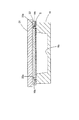
図8は、位置合わせ用突起部16bを雌型16内部に収容可能な他の構成を示した構成図である。また、図9は、位置合わせ用突起部16bが表面板22内部に収容された状態を示した構成図である。図においては、雌型16上面に形成された位置合わせ用突起部16bと相対面する表面板22に当該位置合わせ用突起部16bを収容可能な突起部収容孔22aを形成する。そして、熱成形に際して、上テーブル20が下降動作すると、位置合わせ用突起部16bは突起部収容孔22aに収容される。これによって表面板22下面と雌型16上面とが当接し、型面16a内部を略密封することが可能になる。
【0036】
上述してきた実施形態においては、熱成形装置10を構成するにあたり、上テーブル20に熱板21および表面板22を配設するとともに、下テーブル13に雌型16を配設し、熱成形に際して、上テーブル20を下テーブル13に対して下降動作させる構成を採用した。むろん、このような熱成形装置10を構成する場合、上テーブル20に熱板21および表面板22、下テーブル13に雌型16を配設する構成に限定されるものではなく、その構成は適宜変更可能である。
【0037】
図10は、熱成形装置10の変形例の概略構成を示した構成図である。
同図において、熱成形装置100は、上テーブル200の下側に雌型160が型面160aを下方に向けて配設されるとともに、下テーブル130の上側に熱板210および表面板220が配設される。そして、上テーブル200は上テーブル駆動部230に設置され、同上テーブル駆動部230にて図左右方向に移動可能になっており、作業ゾーンZ1aと成形ゾーンZ2aとの間を往復移動可能になっている。作業者は上テーブル200が作業ゾーンZ1aに移動されると、雌型160に樹脂シートS1を上述した位置合わせ機構を利用して位置合わせしつつセットする。また、下テーブル130は下テーブル駆動部180に設置され、熱成形に際して、エアシリンダ180aの上下動作によって上下動し、表面板220上面を雌型160下面に当接させる。
【0038】
上述してきた実施形態においては、熱成形装置10,100を作業ゾーンZ1,Z1aおよび成形ゾーンZ2,Z2aに分け、下テーブル13あるいは上テーブル200を作業ゾーンZ1,Z1a、成形ゾーンZ2,Z2aにて移動させる手法を採用してるが、むろん、このような構成に限定されるものではなく、単に成形ゾーンZ2,Z2aのみで構成し、この成形ゾーンZ1,Z1aにて樹脂シートS,S1の雌型16,160に対する取り付け作業を行なうようにしても良い。
【0039】
このように、雌型16に位置合わせ用突起部16bを配設するとともに、樹脂シートSを雌型16にセットするに際して、この樹脂シートSに形成された基準マーク孔Mを位置合わせ用突起部16bに装着することによって、簡易な手法で正確に樹脂シートSに印刷された模様Dの型面16aに対する位置合わせを実施することが可能になる。
【図面の簡単な説明】
【図1】本発明の概念を示した技術概念図である。
【図2】本発明にかかる熱成形装置を実現した構成を示した側面構成図である。
【図3】熱成形装置の上面構成図である。
【図4】熱成形装置にて実行される熱成形処理の手順を示したフローチャートである。
【図5】樹脂シートに印刷された所定の模様と雌型の型面との位置合わせを実現可能な位置合わせ機構の構成を示した構成図である。
【図6】位置合わせ用突起部を雌型内部に収容可能な構成を示した構成図である。
【図7】位置合わせ用突起部が雌型内部に収容された状態を示した構成図である。
【図8】位置合わせ用突起部を雌型内部に収容可能な他の構成を示した構成図である。
【図9】位置合わせ用突起部が表面板内部に収容された状態を示した構成図である。
【図10】熱成形装置の変形例の概略構成を示した構成図である。
【符号の説明】
10…熱成形装置
11…基台
12…レール
13…下テーブル
14…車輪
15…エアシリンダ
16…雌型
16a…型面
16b…位置合わせ用突起部
17…ロッド
18…シリンダ軸
19…ダブルトグル
20…上テーブル
21…熱板
22…表面板
D…模様
M…基準マーク孔
S…樹脂シート[0001]
BACKGROUND OF THE INVENTION
The present invention relates to a thermoforming apparatus and a thermoforming method, and more particularly, to a thermoforming apparatus and a thermoforming method for forming a resin sheet printed with a predetermined pattern corresponding to the same pattern.
[0002]
[Prior art]
Conventionally, this type of thermoforming apparatus clamps a resin sheet on a clamp frame. Then, the clamp frame on which the resin sheet is clamped is conveyed to the molding mechanism by the conveyance mechanism. The transport mechanism is constituted by a ball screw, and the clamp frame described above is fitted to the ball screw. The transport mechanism rotates the ball screw during transport. Then, the clamp frame fitted to the ball screw is carried in and out of the forming mechanism in accordance with this rotation operation. That is, the positioning of the resin sheet with respect to the female mold surface arranged in the molding mechanism is performed by the carry-in movement of the clamp frame by the ball screw.
[0003]
[Problems to be solved by the invention]
In the conventional thermoforming apparatus described above, the alignment accuracy of the resin sheet with respect to the female mold surface arranged in the forming mechanism depends on the screw pitch of the ball screw. For this reason, for example, when a predetermined pattern is printed on the resin sheet, and when this pattern is aligned with the mold surface, there is a problem that it is not possible to achieve alignment accuracy higher than this screw pitch. there were.
[0004]
The present invention has been made in view of the above problems, and it is an object of the present invention to provide a thermoforming apparatus and a thermoforming method capable of accurately aligning a pattern printed on a resin sheet with respect to a female mold surface. And
[0005]
[Means for Solving the Problems]
In order to achieve the above object, an invention according to claim 1 is a thermoforming apparatus for thermoforming a resin sheet printed with a predetermined pattern to form a molded product corresponding to the pattern, wherein the resin sheet is A heating plate to be softened by heating, a female mold having a mold surface corresponding to the pattern,The heating plate is erected in the direction of the heating plate on the contact side of the female plate with the heating plate, and when the heating plate and the female mold are in contact with each other, By having a protrusion accommodated in any of the above and fitting the protrusion with a concave reference mark formed on the resin sheet,An alignment mechanism for aligning the pattern printed on the resin sheet with respect to the mold surface, and the heating plate and the female mold are brought into contact with the resin sheet aligned by the alignment mechanism. And a molding mechanism that forms the molded product while heat-softening the resin sheet.
[0006]
In the invention according to claim 1 configured as described above, when providing a thermoforming apparatus for thermoforming a resin sheet printed with a predetermined pattern to form a molded product corresponding to the pattern, an alignment mechanism is provided. AtA protrusion that is erected in the direction of the heating plate on the contact side with the female heating plate and is accommodated in either the heating plate or the female die when the heating plate and the female die are in contact with each other By fitting the part with a concave reference mark formed on the resin sheet,The pattern printed on the resin sheet is aligned with the female mold surface. In the molding mechanism, the molded product is formed while the resin sheet is heated and softened by bringing the heating plate and the female mold into contact with the resin sheet aligned by the alignment mechanism. By aligning in this way, it becomes possible to form a molded product in which the pattern is accurately reflected.
[0008]
During the thermoforming, when the protruding portion erected on the female mold is depressed in accordance with the contact surface between the female mold and the heating plate, the female mold and the heating plate can be brought into close contact with each other. It is preferable because the airtightness of the space formed by the mold and the heating plate can be improved. Therefore,The protrusion is housed in the female mold when the heating plate and the female mold contact each other, or is accommodated in the heating plate when the heating plate and the female mold contact each other.
When the heating plate and the female mold come into contact with each other during thermoforming, the female mold is formed so that the protrusion is accommodated in the female mold.
[0009]
OrWhen the heating plate and the female mold come into contact with each other during thermoforming, the heating plate is formed so that the protrusion is accommodated in the heating plate.
[0010]
In thermoforming, the female mold and the heating plate are brought into contact with each other by a molding mechanism. In the female mold, it is necessary to align the resin sheet and the mold surface by the alignment mechanism as described above. At the time of this alignment, the operator must work between the female mold and the heating plate, which is complicated. Therefore,Claim 2The invention according toClaim 1In the thermoforming apparatus described in (1), a structure is provided that includes a transport mechanism that can carry the female mold in and out of the molding mechanism.
Configured as aboveClaim 2In this invention, the female mold can be carried in and out of the molding mechanism by the transport mechanism. Thereby, since the operator only has to align the resin sheet with the mold surface of the female mold and then carry the resin sheet into the molding mechanism by the transport mechanism, work efficiency is improved.
[0011]
The positional relationship between the female mold and the heating plate is not particularly limited as long as they can be brought into contact with each other during thermoforming. Here, as an example of the positional relationship between the female mold and the heating plate,Claim 3The invention according to claim 1 is directed to claim 1.Or claim 2In the thermoforming apparatus according to any one of the above, the heating plate is arranged on the upper side of the female mold.
Configured as aboveClaim 3In the invention, the heating plate is disposed on the upper side of the female mold. Here, when the heating plate and the female die are brought into contact with each other by thermoforming, the heating plate may be moved downward with respect to the female die, or the female die may be moved upward with respect to the heating plate. . Of course, the heating plate and the female mold may be moved relative to each other.
[0012]
As another example of the positional relationship between the female mold and the heating plate,Claim 4The invention according to claim 1 is directed to claim 1.Or claim 2In the thermoforming apparatus according to any one of the above, the heating plate is arranged on the lower side of the female mold.
Configured as aboveClaim 4In the present invention, the heating plate is disposed on the lower side of the female mold. Here, when the heating plate and the female die are brought into contact with each other by thermoforming, the heating plate may be moved downward with respect to the female die in the same manner as described above, or the female die may be moved upward with respect to the heating plate. You may let them. Of course, the heating plate and the female mold may be moved relative to each other.
[0013]
When alignment is performed by the alignment mechanism, it is preferable that the aligned resin sheet is fixed to the female mold. Therefore,Claim 5The invention according toClaims 1 to 4In the thermoforming device according to any one of the above, the concave shape of the fiducial mark of the resin sheet is formed in the through hole, and the positioning mechanism is configured to insert the protrusion into the through hole to position the position. The configuration is such that alignment is performed.
Configured as aboveClaim 5In this invention, the concave shape of the reference mark of the resin sheet is formed in the through hole. And in aligning with an alignment mechanism, a projection part is inserted in this through-hole. In this way, the resin sheet can be fixed to the female mold by inserting the protrusions into the through holes during alignment.
[0014]
As an example of the specific configuration of the female mold and the alignment mechanism,Claim 6The invention according toClaims 1 to 5In the thermoforming apparatus according to any one of the above, the female die is formed in a substantially quadrangular shape, and the protrusion of the positioning mechanism is erected at a substantially four-way corner of the substantially quadrangular female die. As a configuration.
Configured as aboveClaim 6In the invention, the female die is formed in a substantially square shape, and the protrusion of the positioning mechanism is erected at the substantially four corners of the substantially square female die.
[0015]
In addition, a method of forming a molded product while thermoforming a resin sheet having a mold surface corresponding to the pattern while heat-softening a resin sheet printed with such a predetermined pattern with a heating plate is not necessarily substantial. It is not necessary to be limited to a device, and it can be easily understood that the method functions as well.
For this reason,Claim 7The present invention relates to a thermoforming method in which a resin sheet on which a predetermined pattern is printed is heated and softened by a heating plate, and a molded product is formed by thermoforming with a female mold having a mold surface corresponding to the pattern.The heating plate is erected in the direction of the heating plate on the contact side with the heating plate of the female mold, and when the heating plate and the female mold are in contact, the inside of the heating plate and the inside of the female mold By using the protrusions accommodated in either one, by fitting the protrusions with concave reference marks formed on the resin sheet,An alignment process for aligning a pattern printed on the resin sheet with a mold surface corresponding to the same pattern on the female mold, and the heating plate and the female on the resin sheet aligned in the alignment process And a molding step for forming the molded product while bringing the resin sheet into contact with the mold and heating and softening the resin sheet.
That is, it is not necessarily limited to a substantial apparatus, and there is no difference that the method is also effective.
[0016]
【The invention's effect】
As described above, in the present invention, when a resin sheet on which a predetermined pattern is printed is thermoformed corresponding to this pattern, the alignment between the pattern and the female mold surface can be performed easily and accurately. It is possible to provide a thermoforming apparatus capable of performing the above.
AlsoAccording to the present invention,An example of an alignment mechanism can be presented.
furtherAccording to the present invention,By accommodating the protrusion in the female mold, the contact surface between the female mold and the heating plate can be brought into close contact.
further,Claim 2According to the invention, the alignment work efficiency can be improved.
[0017]
further,Claim 3According to the invention, an example of the arrangement of the female mold and the heating plate can be presented.
further,Claim 4According to the invention, another example of the arrangement of the female mold and the heating plate can be presented.
further,Claim 5According to the invention, the resin sheet after alignment can be fixed to the female mold with a simple configuration.
further,Claim 6According to the invention, specific configurations of the female mold and the alignment mechanism can be presented.
further,Claim 7According to the invention, when a resin sheet on which a predetermined pattern is printed is thermoformed corresponding to this pattern, it is possible to easily and accurately align the pattern with the female mold surface. A thermoforming method can be provided.
[0018]
DETAILED DESCRIPTION OF THE INVENTION
Here, embodiments of the present invention will be described in the following order.
(1) Summary of the invention:
(2) Configuration of thermoforming device:
(3) About thermoforming processing procedure:
(4) About alignment of resin sheet:
(5) Modification of thermoforming device:
(6) Summary:
[0019]
(1) Summary of the invention:
FIG. 1 is a technical conceptual diagram showing the concept of the present invention.
In the figure, a thermoforming apparatus C according to the present invention includes a heating plate C1, a female mold C2, an alignment mechanism C3, and a forming mechanism C4. And the said thermoforming apparatus C forms the molded product corresponding to the pattern A1 by thermoforming the resin sheet A on which the predetermined pattern A1 was printed. The female mold C2 has a mold surface C21 corresponding to the pattern A1 printed on the resin sheet A, and is printed on the resin sheet A based on the reference mark A2 provided on the resin sheet A by the alignment mechanism C3. The pattern A1 is aligned with the mold surface C21.
[0020]
During thermoforming, the heating plate C1 heats and softens the resin sheet A, and the heating plate C1 and the female die C2 are brought into contact with the resin sheet A aligned by the alignment mechanism C3 by the forming mechanism C4. A molded product is formed while the resin sheet A is softened by heating. As described above, the pattern A1 and the mold surface C21 are aligned by the alignment mechanism C3 using the reference mark A2 given to the resin sheet A, so that the accurate pattern A1 and the mold can be easily and simply obtained by a simple method. It is possible to perform alignment with the surface C21.
[0021]
(2) Configuration of thermoforming device:
FIG. 2 is a side configuration diagram of the thermoforming apparatus showing a configuration realizing the thermoforming apparatus C according to the present invention.
In FIG. 1, a
[0022]
Here, the lower table 13 is connected to an air cylinder 15 whose cylinder shaft extends and contracts with respect to the back side in the figure. The lower table 13 is moved on the rail 12 by the expansion / contraction operation of the cylinder shaft by the air cylinder 15. A female die 16 is placed and fixed on the upper surface of the lower table 13. Accordingly, the
[0023]
On the other hand, an upper table 20 having both end portions fitted to the rods 17 and 17 is connected to the lower end portion of the double toggle 19. Therefore, the upper table 20 moves up and down while being regulated in the axial direction of the rods 17 and 17 as the cylinder shaft 18b of the air cylinder 18a disposed in the upper table drive unit 18 expands and contracts. . A
[0024]
With this configuration, during thermoforming, the resin sheet that is the object to be heat-molded is placed on the female die 16 and the air cylinder 15 is driven and controlled so that the lower table 13 is moved to a position facing the upper table 20. To do. Then, the female die 16 and the
[0025]
FIG. 3 is a top view of the
In the figure, the
[0026]
Next, the flowchart of FIG. 4 shows the procedure of the thermoforming process executed by the
In the figure, when the lower table 13 is first moved on the operation panel OP, the air cylinder 15 is driven. As a result, the female die 16 is moved to the work zone Z1 (step S100). Next, the resin sheet to be heat-molded is set while being aligned with the female die 16 that has been moved to the work zone Z1 (step S105). When the setting of the resin sheet with respect to the female die 16 is completed, the lower table 13 is moved on the operation panel OP. By this moving operation, the air cylinder 15 is driven to move the female die 16 to the molding zone Z2 (step S110). When the movement to the forming zone Z2 is completed, the start of thermoforming is instructed on the operation panel OP.
[0027]
Then, the
[0028]
In the present embodiment, a resin sheet on which a predetermined pattern is printed on the object to be thermoformed is used. When the resin sheet on which a predetermined pattern is printed in this way is thermoformed, if the position of the pattern portion with respect to the mold surface of the
[0029]
FIG. 5 is a configuration diagram showing a configuration of an alignment mechanism capable of realizing alignment between a predetermined pattern printed on the resin sheet and the mold surface of the
In the figure, the resin sheet S is formed in a substantially square shape, and a pattern D is printed at a substantially central portion. And the reference mark as a position reference of this pattern D is given to the substantially four corners of the resin sheet S. In the present embodiment, a reference mark hole M in which a through hole is formed is adopted as the reference mark. Of course, the present invention is not limited to the mode of forming the through hole, and may simply be printed with the reference mark. On the other hand, in the
[0030]
By inserting the reference mark hole M formed in the resin sheet S into the
[0031]
In the present embodiment, four reference mark holes M are formed in the resin sheet S, and four
[0032]
Thus, it is possible to perform alignment by forming the
[0033]
FIG. 6 is a configuration diagram showing a configuration in which the
[0034]
At this time, the
[0035]
FIG. 8 is a configuration diagram showing another configuration in which the
[0036]
In the embodiment described above, in configuring the
[0037]
FIG. 10 is a configuration diagram showing a schematic configuration of a modified example of the
In the figure, in the thermoforming apparatus 100, a female mold 160 is disposed below the upper table 200 with the mold surface 160 a facing downward, and a hot plate 210 and a surface plate 220 are disposed above the lower table 130. Established. The upper table 200 is installed in the upper table driving unit 230, and can be moved in the horizontal direction in the figure by the upper table driving unit 230, and can be reciprocated between the work zone Z1a and the molding zone Z2a. Yes. When the upper table 200 is moved to the work zone Z1a, the operator sets the resin sheet S1 on the female mold 160 while aligning it using the above-described alignment mechanism. In addition, the lower table 130 is installed in the lower table driving unit 180, and moves up and down by the vertical movement of the air cylinder 180a during thermoforming so that the upper surface of the surface plate 220 abuts the lower surface of the female die 160.
[0038]
In the embodiment described above, the
[0039]
As described above, the
[Brief description of the drawings]
FIG. 1 is a technical conceptual diagram showing the concept of the present invention.
FIG. 2 is a side configuration diagram showing a configuration realizing a thermoforming apparatus according to the present invention.
FIG. 3 is a top view of the thermoforming apparatus.
FIG. 4 is a flowchart showing a procedure of thermoforming processing executed by the thermoforming apparatus.
FIG. 5 is a configuration diagram showing a configuration of an alignment mechanism that can realize alignment between a predetermined pattern printed on a resin sheet and a female mold surface;
FIG. 6 is a configuration diagram showing a configuration in which the alignment protrusion can be accommodated in the female mold.
FIG. 7 is a configuration diagram showing a state in which the alignment protrusion is housed in the female mold.
FIG. 8 is a configuration diagram showing another configuration in which the alignment protrusion can be accommodated in the female mold.
FIG. 9 is a configuration diagram showing a state in which the alignment protrusion is housed inside the surface plate.
FIG. 10 is a configuration diagram showing a schematic configuration of a modified example of the thermoforming apparatus.
[Explanation of symbols]
10 ... Thermoforming device
11 ... Base
12 ... Rail
13 ... Lower table
14 ... wheel
15 ... Air cylinder
16 ... Female type
16a ... Mold surface
16b ... Positioning projection
17 ... Rod
18 ... Cylinder shaft
19 ... Double toggle
20 ... Upper table
21 ... Hot plate
22 ... Surface plate
D ... Pattern
M ... Reference mark hole
S ... Resin sheet
Claims (7)
上記樹脂シートを加熱軟化させる加熱板と、
上記模様に対応した型面を有する雌型と、
上記雌型の上記加熱板との当接側に同加熱板方向に立設されるとともに、同加熱板と同雌型とが当接した際に同加熱板の内部と同雌型の内部とのいずれかに収容される突起部を有し、同突起部を上記樹脂シートに形成された凹形状の基準マークと嵌合させることにより、同樹脂シートに印刷された模様を上記型面に対して位置合わせする位置合わせ機構と、
上記位置合わせ機構にて位置合わせされた樹脂シートに上記加熱板と上記雌型とを当接させて同樹脂シートを加熱軟化させつつ上記成形品を形成する成形機構とを具備することを特徴とする熱成形装置。A thermoforming apparatus for forming a molded product corresponding to the pattern by thermoforming a resin sheet on which a predetermined pattern is printed,
A heating plate for heating and softening the resin sheet;
A female mold having a mold surface corresponding to the pattern;
The heating plate is erected in the direction of the heating plate on the contact side of the female plate with the heating plate, and when the heating plate and the female mold are in contact with each other, The projection printed on the resin sheet is formed on the mold surface by fitting the protrusion with a concave reference mark formed on the resin sheet. An alignment mechanism for aligning
And a molding mechanism for forming the molded product while bringing the heating plate and the female die into contact with the resin sheet aligned by the alignment mechanism to heat and soften the resin sheet. Thermoforming equipment.
上記雌型の上記加熱板との当接側に同加熱板方向に立設されるとともに、同加熱板と同雌型とが当接した際に同加熱板の内部と同雌型の内部とのいずれかに収容される突起部を用い、同突起部を上記樹脂シートに形成された凹形状の基準マークと嵌合させることにより、同樹脂シートに印刷された模様を上記雌型の同模様に対応した型面に対して位置合わせする位置合わせ工程と、
上記位置合わせ工程にて位置合わせされた樹脂シートに上記加熱板と上記雌型とを当接させ同樹脂シートを加熱軟化させつつ上記成形品を形成する成形工程とを具備することを特徴とする熱成形方法。In a thermoforming method of forming a molded product while thermoforming a female sheet having a mold surface corresponding to the pattern while softening a resin sheet printed with a predetermined pattern with a heating plate,
The heating plate is erected in the direction of the heating plate on the contact side of the female plate with the heating plate, and when the heating plate and the female mold are in contact with each other, By using the protrusions accommodated in any of the above, and by fitting the protrusions with concave reference marks formed on the resin sheet, the pattern printed on the resin sheet is the same pattern of the female mold. An alignment process for aligning with the mold surface corresponding to
A molding step of forming the molded product while bringing the heating plate and the female die into contact with the resin sheet aligned in the alignment step and softening the resin sheet by heating. Thermoforming method.
Priority Applications (1)
| Application Number | Priority Date | Filing Date | Title |
|---|---|---|---|
| JP2001380195A JP3798309B2 (en) | 2001-12-13 | 2001-12-13 | Thermoforming apparatus and thermoforming method |
Applications Claiming Priority (1)
| Application Number | Priority Date | Filing Date | Title |
|---|---|---|---|
| JP2001380195A JP3798309B2 (en) | 2001-12-13 | 2001-12-13 | Thermoforming apparatus and thermoforming method |
Related Child Applications (1)
| Application Number | Title | Priority Date | Filing Date |
|---|---|---|---|
| JP2003331377A Division JP2004001586A (en) | 2003-09-24 | 2003-09-24 | Thermoforming device and method therefor |
Publications (2)
| Publication Number | Publication Date |
|---|---|
| JP2003181911A JP2003181911A (en) | 2003-07-03 |
| JP3798309B2 true JP3798309B2 (en) | 2006-07-19 |
Family
ID=27591345
Family Applications (1)
| Application Number | Title | Priority Date | Filing Date |
|---|---|---|---|
| JP2001380195A Expired - Lifetime JP3798309B2 (en) | 2001-12-13 | 2001-12-13 | Thermoforming apparatus and thermoforming method |
Country Status (1)
| Country | Link |
|---|---|
| JP (1) | JP3798309B2 (en) |
Families Citing this family (5)
| Publication number | Priority date | Publication date | Assignee | Title |
|---|---|---|---|---|
| JP5554016B2 (en) * | 2009-05-29 | 2014-07-23 | 株式会社プラネット | Decorative panel and its manufacturing equipment |
| JP5903930B2 (en) * | 2012-02-27 | 2016-04-13 | 日新イオン機器株式会社 | Substrate transfer apparatus and semiconductor manufacturing apparatus using the substrate transfer apparatus |
| ITPD20130070A1 (en) * | 2013-03-21 | 2014-09-22 | Composite Solution Srl | THERMOFORMING PROCESS OF A LASTRIFORM ELEMENT IN COMPOSITE POLYMERIC MATERIAL AND MOLD OPERATING IN AGREEMENT WITH THIS PROCESS |
| JP7322557B2 (en) * | 2019-07-10 | 2023-08-08 | マツダ株式会社 | Decorative member manufacturing apparatus, decorative member manufacturing method using the manufacturing apparatus, and shaped member formed by the manufacturing method |
| JP7326947B2 (en) * | 2019-07-10 | 2023-08-16 | マツダ株式会社 | Decorative member manufacturing apparatus, decorative member manufacturing method using the manufacturing apparatus, and shaped member formed by the manufacturing method |
-
2001
- 2001-12-13 JP JP2001380195A patent/JP3798309B2/en not_active Expired - Lifetime
Also Published As
| Publication number | Publication date |
|---|---|
| JP2003181911A (en) | 2003-07-03 |
Similar Documents
| Publication | Publication Date | Title |
|---|---|---|
| JP5893303B2 (en) | Imprint apparatus and article manufacturing method using the same | |
| JP3798309B2 (en) | Thermoforming apparatus and thermoforming method | |
| KR101183207B1 (en) | Apparatus for attaching reinforcement to fpcb and zig assembly for the fpcb | |
| KR101821523B1 (en) | Apparatus and method for fusing using heating and vibration | |
| CN205553185U (en) | Heating device for vamp vacuum plastic former | |
| JP4317302B2 (en) | Thermoforming equipment | |
| JP2004001586A (en) | Thermoforming device and method therefor | |
| CN210586479U (en) | Thermal shaping equipment | |
| JP4166722B2 (en) | Thermoforming apparatus and method for cleaning thermoforming apparatus | |
| JP4944938B2 (en) | Vacuum forming apparatus and vacuum forming method | |
| JPH1177400A (en) | Positioning method and positioning device for sheet material | |
| KR101062994B1 (en) | Low Pressure Vacuum Forming Machine With Vacuum Sealing Means | |
| JPH03293793A (en) | Reinforcing board-mounting device on flexible printed-circuit board | |
| JP3948647B2 (en) | Sheet material positioning method and positioning apparatus | |
| JP2005297399A5 (en) | ||
| JP2009028996A (en) | Stamper and stamper attaching method | |
| JP2005081840A (en) | Process and equipment to form molding sheet | |
| JP3289956B2 (en) | Light beam sealing method | |
| JPH10263740A (en) | Numerical controlled sequentially forming device, and its method | |
| JP2861821B2 (en) | Mold press equipment | |
| CN209747476U (en) | Improved die bonder | |
| CN111648049B (en) | Sewing path fine adjustment method applied to automatic sewing system | |
| CN216708116U (en) | Injection mold without ejector rod trace | |
| JPH1177815A (en) | Molding equipment of laminated molded material | |
| JP2024066267A (en) | SHEET HOLDING MECHANISM, MOLD, FORMING MACHINE, FORMING SYSTEM, METHOD FOR PRODUCING FORMED PRODUCT, AND METHOD FOR PRODUCING FORMED SHEET |
Legal Events
| Date | Code | Title | Description |
|---|---|---|---|
| A977 | Report on retrieval |
Free format text: JAPANESE INTERMEDIATE CODE: A971007 Effective date: 20040514 |
|
| A131 | Notification of reasons for refusal |
Free format text: JAPANESE INTERMEDIATE CODE: A131 Effective date: 20040525 |
|
| A521 | Written amendment |
Free format text: JAPANESE INTERMEDIATE CODE: A523 Effective date: 20040726 |
|
| A711 | Notification of change in applicant |
Free format text: JAPANESE INTERMEDIATE CODE: A711 Effective date: 20040930 |
|
| RD02 | Notification of acceptance of power of attorney |
Free format text: JAPANESE INTERMEDIATE CODE: A7422 Effective date: 20050221 |
|
| A131 | Notification of reasons for refusal |
Free format text: JAPANESE INTERMEDIATE CODE: A131 Effective date: 20050928 |
|
| TRDD | Decision of grant or rejection written | ||
| A01 | Written decision to grant a patent or to grant a registration (utility model) |
Free format text: JAPANESE INTERMEDIATE CODE: A01 Effective date: 20060412 |
|
| A61 | First payment of annual fees (during grant procedure) |
Free format text: JAPANESE INTERMEDIATE CODE: A61 Effective date: 20060419 |
|
| R150 | Certificate of patent or registration of utility model |
Free format text: JAPANESE INTERMEDIATE CODE: R150 Ref document number: 3798309 Country of ref document: JP Free format text: JAPANESE INTERMEDIATE CODE: R150 |
|
| FPAY | Renewal fee payment (event date is renewal date of database) |
Free format text: PAYMENT UNTIL: 20120428 Year of fee payment: 6 |
|
| R250 | Receipt of annual fees |
Free format text: JAPANESE INTERMEDIATE CODE: R250 |
|
| FPAY | Renewal fee payment (event date is renewal date of database) |
Free format text: PAYMENT UNTIL: 20120428 Year of fee payment: 6 |
|
| FPAY | Renewal fee payment (event date is renewal date of database) |
Free format text: PAYMENT UNTIL: 20150428 Year of fee payment: 9 |
|
| R250 | Receipt of annual fees |
Free format text: JAPANESE INTERMEDIATE CODE: R250 |
|
| R250 | Receipt of annual fees |
Free format text: JAPANESE INTERMEDIATE CODE: R250 |
|
| R250 | Receipt of annual fees |
Free format text: JAPANESE INTERMEDIATE CODE: R250 |
|
| R250 | Receipt of annual fees |
Free format text: JAPANESE INTERMEDIATE CODE: R250 |
|
| EXPY | Cancellation because of completion of term |