JP3797164B2 - Electronic keyboard instrument - Google Patents
Electronic keyboard instrument Download PDFInfo
- Publication number
- JP3797164B2 JP3797164B2 JP2001277195A JP2001277195A JP3797164B2 JP 3797164 B2 JP3797164 B2 JP 3797164B2 JP 2001277195 A JP2001277195 A JP 2001277195A JP 2001277195 A JP2001277195 A JP 2001277195A JP 3797164 B2 JP3797164 B2 JP 3797164B2
- Authority
- JP
- Japan
- Prior art keywords
- subtone
- hole
- speaker
- holes
- housing
- Prior art date
- Legal status (The legal status is an assumption and is not a legal conclusion. Google has not performed a legal analysis and makes no representation as to the accuracy of the status listed.)
- Expired - Fee Related
Links
Images


Description
【0001】
【発明の属する技術分野】
この発明は、電子鍵盤楽器に関し、特にスピーカからの放音構造の改良に関する。
【0002】
【従来技術】
全体としてフラットな盤状の筐体形状を有する電子鍵盤楽器において、従来のスピーカ配置構造としては、筐体上面に放音開口部を設け、この開口部に前面を向けてスピーカを配設するタイプのものや、筐体背面に放音開口部を設け、この開口部に前面を向けてスピーカを配設するタイプのもの等がある。前者の場合、音は楽器上方に放音されるので、例えば、楽器後方の或る程度離れた位置に聴衆を想定した場合、この聴衆側への音の通りが十分でない。一方、後者のようにスピーカを楽器後方に向けて配設した場合は、聴衆側への音の通りは向上するが、楽器前面の鍵盤に対面している演奏者の側での音の通りが十分でない。このため、演奏者への音のフィードバックがよくないことからくる鍵タッチレスポンスの違和感によるミスタッチが生じ、ひいては演奏表現力の低下をきたす。
これに対して、実公昭62−103382号公報においては、楽器の筐体の背面寄りの所定個所に斜め上向きにスピーカを配設することで、聴衆側と演奏者側の両側での音響特性向上を図ったものが示されている。しかし、このように斜め上方にスピーカを向けるものでは、前方(演奏者寄り)及び後方(聴衆寄り)に対する音響特性に限界があり、これでは不十分であった。また、製造組立上、容易でなく、コストアップになっていた。
一般に、低音域は音の伝播が回折しやすいため、スピーカの配置(スピーカ前面の指向方向)に関わらず、どの位置で聴いても比較的良好に聞き取り易い。一方、高音域は、スピーカの配置の影響を受け、音の通りが十分でない位置においては聞き取り難くなる。従って、上述の従来技術においては、特に高音域での音響特性が問題となる。
【0003】
【発明の解決しようとする課題】
例えば高音域の音響特性を補償するために高音域用のスピーカを増設したり、あるいは異なる放音指向方向で複数のスピーカを設けることで、聴者の位置にかかわらず音響特性を向上させることが可能である。しかしそうすると、製造コストが高くなり、また楽器筐体が必然的に大型化してしまう、という問題が生じる。
本発明は上述の点に鑑みてなされたもので、簡単な構成で、聴衆側と演奏者側のいずれの位置においても音響特性を良好にすることができる電子鍵盤楽器を提供しようとするものである。
【0004】
【課題を解決するための手段】
本発明は、筐体の前面寄りに設けられた鍵盤部と、前記筐体の背面においてスピーカ前面に対応するサイズで設けられた左右 1 対のメイントーンホールと、該各メイントーンホールに前面を向けて前記筐体内に設けられた左右 1 対のスピーカとを具備した電子鍵盤楽器において、前記筐体の上面において、前記各スピーカの側面に対応し且つ該スピーカの奥行き長の奥行き範囲内の所定個所に、それぞれ 1 個のサブトーンホールを穿設してなり、前記各サブトーンホールは、横長の孔からなっていて、該サブトーンホールの長辺が前記スピーカの放音軸に対して直角をなすように配置されてなり、前記各サブトーンホールの中心がそれぞれに対応する前記各スピーカの中心軸線から左又は右端寄りにずれるように該サブトーンホールを配置し、これにより左右 1 対のメイントーンホールの中心間の離隔間隔よりも左右 1 対のサブトーンホールの中心間の離隔間隔の方が大となるようにしてなり、前記各サブトーンホールの開口面積が対応する前記メイントーンホール全体のサイズよりも小さいことを特徴とする。
また、本発明は、筐体の前面寄りに設けられた鍵盤部と、前記筐体の背面においてその左右端寄りに離隔して設けられた左右1対のメイントーンホールと、該各メイントーンホールに前面を向けて前記筐体内に設けられた左右1対のスピーカとを具備した電子鍵盤楽器において、前記筐体の上面において、前記各スピーカの側面に対応する所定個所にそれぞれ1個のサブトーンホールを穿設してなり、前記各サブトーンホールの中心がそれぞれに対応する前記各スピーカの中心軸線から左又は右側面寄りにずれるように該サブトーンホールを配置し、これにより左右1対のメイントーンホールの中心間の離隔間隔よりも左右1対のサブトーンホールの中心間の離隔間隔の方が大となるようにしたことを特徴とする。
【0005】
筐体内に設けられたスピーカの前面が該筐体の背面に設けられたメイントーンホールに向き、スピーカ前面からの音響出力が楽器の後方を指向して(例えば聴衆の方向を指向して)放音される。スピーカ前面からの音は、楽器の後方に向けて放音されるが、低音域は回折しやすいので、楽器前面の鍵盤に対面している演奏者の側においても、良く響く。一方、サブトーンホールが筐体の上面においてスピーカの側面に対応する所定個所に穿設されていることで、スピーカ側面からの音響振動がこのサブトーンホールから上方に放音される。このサブトーンホールから上方に放音された音は、楽器前面に位置する演奏者において聴き取り易いので、回折音において不足している成分特に高音域成分が補われることになる。このため、演奏者側においても高音域が落ちることがない。また、楽器の後方(例えば聴衆側)においては、低音域が強調され高音域も良く通る。従って、単にサブトーンホールを設けるだけの簡単な構成で、聴衆側と演奏者側のいずれの位置においても音響特性を良好にすることができる。
【0006】
【発明の実施の形態】
以下、添付図面を参照して本発明の一実施例について説明する。
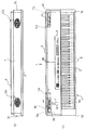
図1(a)は、本発明に係る電子鍵盤楽器の一例の上面を示す平面図であり、この電子鍵盤楽器を矢印aから矢視した背面図を図1(b)に示す。なお、(b)に示す背面図においては天地が逆に表されている。本実施例に係る電子鍵盤楽器の筐体1は、後方上面部を成す屋根板部2と、底面部を成す底板部4と、左右側面部を成す左右の側板部5a、5bと、背面部を成す背面板部7と、前面部を成す口棒部6とで構成される。筐体1の前方上面には鍵盤部3が配置されており、該鍵盤部3の内部機構は該筐体1内部に収納されている。屋根板部2の所定個所には各種操作スイッチ等を含む操作パネル9が設けられている。
【0007】
筐体1の内部において、後方の背面板部7寄りの所定個所に、ステレオ用の左右スピーカ12a、12b(図1において点線で示す。)が配設されており、該スピーカ12a、12bの前面つまり放音口は楽器後方の背面板部7の方を指向している。背面板部7には、図1(b)に示すように、左右スピーカ12a、12bの前面の放音口に対応してメイントーンホール10a、10bがそれぞれ設けられている。図の例において、各メイントーンホール10a、10bは、長細の複数の小孔の集合からなり、それぞれの小孔集合が全体としてスピーカのコーンサイズつまり放音口のサイズに略対応する。このように、各スピーカ12a、12bは、それぞれに対応するメイントーンホール10a、10bに前面つまり放音口を向けて配設されており、スピーカ前面から放たれる音はメイントーンホール10a、10bを通して楽器後方に放音される。
【0008】
屋根板部2において、左右各スピーカ12a、12bの側面の上方に相当する所定個所にサブトーンホール11a、11bがそれぞれ穿設されている。図2は、スピーカ12aとサブトーンホール11aとの位置関係の一例を示すもので、図1(a)のX−X線に沿う断面図である。図の例では、背面板部7に取り付けられたスピーカ12aのコア部の上方にサブトーンホール11aが穿設されている。もう一方のサブトーンホール11bも同様である。サブトーンホール11aの上面は、着脱自在なサランネット13で覆われている。なお、図示の都合上、サランネット13は、図1(a)では図示を省略し、図2では一点鎖線で示した。サブトーンホール11aの周囲には、サランネット載置凹部14aが形成されており、ここにサランネット13が載置される。もう一方のサブトーンホール11bにも同様にサランネット載置凹部14bが形成されている。
【0009】
一例として、サブトーンホール11a、11bは図1(a)に示すような横長の孔からなっており、孔の中心Qがスピーカの放音軸Sから適宜ずらして配設される。好ましくは、本実施例で示すように、サブトーンホールの中心Qをスピーカの放音軸Sから楽器の左右側面方向に適宜の距離dだけずらして配設すると良い。すなわち、左側のサブトーンホール11aは図1(a)において左方向、右側のサブトーンホール11bは図1(a)において右方向に、それぞれ孔の中心Qがスピーカの中心つまり放音軸Sからdだけずらして配設される。サブトーンホール11a、11bを、それぞれ左右方向に離して設けることは、音のセパレーションという点で好ましい。しかしこれに限らず、各スピーカ12a、12bの上方に適宜の配置でサブトーンホールを設けるようにしてよい。
【0010】
図1(a)に示すようにサブトーンホール11a、11bを長孔に形成して、その長辺が放音軸Sに対して直角をなすようにすると、効果的である。しかし、サブトーンホール11a、11bの形状は長孔に限らず、円形、楕円、多角形等適宜の形状であってもよい。
屋根板部2においてサブトーンホール11a、11bを設けるべきスピーカの側面に対応する所定個所は、図1(a)に示すように、スピーカ12a、12bの奥行き長Hの範囲内とするとよい。これにより、スピーカからの音響振動を効率よく上方に放音させることができる。しかしこれに限らず、この範囲より幾分はずれた位置にサブトーンホールを設けてもよい。
各サブトーンホール11a、11bの開口面積はメイントーンホール10a、10bの面積より小さい。例えば、概ね3〜15cm2を目安とし、放音性能等を鑑みて10cm2程度が好ましい。
【0011】
屋根板部2は、左右及び中央の仕切り板8a〜8c(図1(a)において点線で示す)を介して背面板部7と結合されている。該板8a〜8cは、屋根板部2と背面板部7とを結合保持する結合保持板になっていて、板8bのみが、音分離のための仕切り板の役目を果たしている。左右の仕切り板8a、8cは左右の各スピーカ12a、12bよりも側板部5a、5b寄りに配置されており、各スピーカ12a、12bの中間に中央の仕切り板8bが位置する。仕切り板8a〜8cは屋根板部2、背面板部7と底板部4を結合する接続補強部材として機能する。すなわち、中央の仕切り板8bに関して図2に示されるように、該仕切り板8bは、上端部で屋根板部2と結合され、下端部で底板部4と結合されており、更に、図には表れていないが、後端部で背面板部7に結合されている。他の仕切り板8a、8cも同様である。なお、便宜上、図2では、鍵盤部3は2点鎖線で略示し、詳細な構造の図示は省略する。なお、中央の仕切り板8bは、上記接続補強部材として機能するのみならず、左右スピーカ12a,12b間の音響分離に優れた効果を発揮する。
【0012】
以上の構成により、スピーカ12a、12bの前面放音口が背面板部7に設けられたメイントーンホール10a、10bに向き、前面放音口からの音響出力が楽器の後方を指向して(例えば聴衆の方向を指向して)放音される。前面放音口からの音は、楽器の後方に向けて放音されるが、低音域は回折しやすいので、楽器前面の鍵盤部3に対面している演奏者の側においても、良く響く。屋根板部2において左右各スピーカ12a、12bの側面の上方に相当する個所にサブトーンホール11a、11bが穿設されているので、スピーカ側面からの音響振動がこのサブトーンホールから上方に放音される。サブトーンホール11a、11bから上方に放音される音は、楽器前面に位置する演奏者において聴き取り易いので、回折音において不足している成分特に高音域成分が補われることになる。このため、演奏者側において不足しがちであった高音域成分が補われ良好な音響特性が得られる。楽器の後方(例えば聴衆側)においては、全域成分がメイントーンホール10a、10bから放音されるともに、サブトーンホール11a、11bから放音された音響成分により音響特性をより一層良好にしている。
以上、本実施例を説明したが、上記サブトーンホール11a、11bの配置は、なるべくスピーカ12a、12bの近くが望ましい。極論すると、屋根板部2や背面板部7のバリアが全くない方が高音域を直達させられるが、音響振動板として屋根板部2や背面板部7等による低音域レベルのアップのためには、そうもいかない。そこでスピーカコーン裏面からの振動を直達するためのサブトーンホールとしてはコーンに最も近いところが望ましい。
とすると、コーン12Pの上方矢印部2Xがよいが、屋根板部2の後方端面とサブトーンホール11a、11bとの距離が小さくなり強度を保てないことから、本実施例では、サブトーンホール11a、11bの配置位置を、図2に示したようにコア部12Mの上方とした。
このようにしても、実験結果は後述のように良好であった。
【0013】
本実施例に従って得られる音響特性の実測例を図3を参照して説明する。図3は、本実施例に係る電子鍵盤楽器を高さ1mの台に載置し、鍵盤部3の中央の上方略々45cmの高さで更にその前方約15cmのところにマイクロフォンを設置し、スピーカ12a,12bから発生される演奏音を該マイクロフォンで集音した音響信号の周波数特性を示すものである。マイクロフォンの位置は概ね演奏者の耳の位置に対応しているので、図3に示す特性は、演奏者によって聞き取られる演奏音の周波数特性に対応している。縦軸に音圧レベルを示し、横軸に周波数を示す。図3によれば、音圧レベルは、周波数約200〜400Hzの間で比較的高い値を示しているが、それ以降でも約4kHz辺りまであまり落ちていない。電子鍵盤楽器で発生させる音域は例えばピアノの88鍵の場合約27Hz〜約4kHz程度であるので、必要な音域全体にわたって良好な周波数特性が得られることが理解できる。
【0014】
なお、上記実施例において、メイントーンホール10a,10bは細長の複数の小孔の集合からなるものであったが、これに限らず、スピーカの放音口サイズに略々対応する一つの大孔であってもよく、その場合メイントーンホールがサランネット等で覆われていてもよい。
【0015】
【発明の効果】
以上のように、本発明によると、低コスト、コンパクトかつ簡単な構造で、聴衆者側と演奏者側のいずれの位置においても音響特性を良好にした電子鍵盤楽器を提供できるという優れた効果を奏する。
【図面の簡単な説明】
【図1】 (a)は本発明に係る電子鍵盤楽器の一実施例を示す平面図、(b)は同実施例に係る電子鍵盤楽器の背面図。
【図2】 図1(a)のX−X線断面図。
【図3】 同実施例に係る電子鍵盤楽器の演奏者側における周波数特性の実測例を示すグラフ。
【符号の説明】
1 筐体
2 屋根板部
3 鍵盤部
4 底板部
5a,5b 側板部
6 口棒部
7 背面板部
8a〜8c 仕切り板
9 操作パネル
10a,10b メイントーンホール
11a,11b サブトーンホール
12a,12b スピーカ
13 サランネット
14a,14b サランネット載置凹部[0001]
BACKGROUND OF THE INVENTION
The present invention relates to an electronic keyboard instrument, and more particularly to an improvement in a sound emission structure from a speaker.
[0002]
[Prior art]
In an electronic keyboard instrument having a flat board-like casing as a whole, the conventional speaker arrangement structure is a type in which a sound emitting opening is provided on the top of the casing and the speaker is arranged with the front facing this opening. And a type in which a sound emitting opening is provided on the rear surface of the housing, and a speaker is disposed with the front facing the opening. In the former case, since the sound is emitted above the musical instrument, for example, when the audience is assumed to be located some distance behind the musical instrument, the passage of the sound to the audience is not sufficient. On the other hand, when the speaker is arranged facing the rear of the instrument as in the latter case, the sound passing to the audience is improved, but the sound passing by the performer facing the keyboard on the front of the instrument is improved. not enough. For this reason, a mistouch due to a sense of incongruity of the key touch response due to poor feedback of sound to the performer results in a decrease in performance expressiveness.
On the other hand, in Japanese Utility Model Publication No. 62-103382, an acoustic characteristic is improved on both the audience side and the performer side by arranging a speaker obliquely upward at a predetermined position near the back of the casing of the musical instrument. Is shown. However, in the case where the speaker is directed obliquely upward as described above, there is a limit to the acoustic characteristics of the front (near the player) and the rear (near the audience), which is insufficient. In addition, it is not easy to manufacture and assemble, and the cost is increased.
In general, since the propagation of sound is easily diffracted in the low sound range, it is relatively easy to hear regardless of the position of the speaker (directivity direction on the front surface of the speaker). On the other hand, the high sound range is affected by the arrangement of the speakers, and is difficult to hear at a position where the passage of sound is not sufficient. Therefore, in the above-described prior art, the acoustic characteristic particularly in the high sound range becomes a problem.
[0003]
[Problem to be Solved by the Invention]
For example, it is possible to improve the sound characteristics regardless of the position of the listener by adding speakers for the high sound range to compensate for the sound characteristics in the high sound range, or providing multiple speakers in different sound emission directivity directions. It is. However, if it does so, the manufacturing cost will become high and the problem that a musical instrument housing will necessarily enlarge will arise.
The present invention has been made in view of the above points, and it is an object of the present invention to provide an electronic keyboard instrument that can improve acoustic characteristics at any position on the audience side and the performer side with a simple configuration. is there.
[0004]
[Means for Solving the Problems]
The present invention includes a keyboard section provided on the front side of the housing, wherein a pair of left and right main tone holes formed in the size corresponding to Oite speaker front to back of the housing, to the respective main tone hole in the electronic keyboard musical instrument and a pair of left and right speaker provided in the housing towards the front, the the upper surface of the housing, wherein the depth range of the depth lengths of the corresponding and the speaker to the side of the speakers of the predetermined position, each made by bored one sub tone holes, each sub-tone hole, consist oblong hole, the long side of the sub-tone hole is normal to the sound emission axis of the speaker is arranged to form result in the place each sub tone the said sub-tone hole so as to shift to the left or right end from the central axis of each speaker center of the hole corresponds to each of this Towards the separation distance between the centers of a pair of right and left sub-tone hole than separation distance between the centers of a pair of right and left main tone hole is set to be large by the said opening area of each sub-tone hole corresponding It is characterized by being smaller than the overall size of the main tone hole .
In addition, the present invention provides a keyboard portion provided near the front surface of the housing, a pair of left and right main tone holes provided on the rear surface of the housing and spaced apart from the left and right ends thereof, and the main tone holes. In an electronic keyboard instrument comprising a pair of left and right speakers provided in the housing with the front facing toward each other, one subtone hole is provided at a predetermined position corresponding to the side surface of each speaker on the top surface of the housing. The subtone holes are arranged so that the centers of the respective subtone holes are shifted to the left or right side from the center axis of the corresponding speakers, whereby a pair of left and right main tone holes is formed. The distance between the centers of the pair of left and right subtone holes is larger than the distance between the centers.
[0005]
The front surface of the speaker provided in the housing is directed to the main tone hole provided on the back surface of the housing, and the sound output from the front surface of the speaker is directed toward the back of the instrument (for example, directed to the audience). Sounded. The sound from the front of the speaker is emitted toward the back of the instrument, but the low frequency range is easily diffracted, so it resonates well even on the player's side facing the keyboard on the front of the instrument. On the other hand, since the subtone hole is formed at a predetermined position corresponding to the side surface of the speaker on the upper surface of the housing, acoustic vibration from the side surface of the speaker is emitted upward from the subtone hole. Since the sound emitted upward from the subtone hole is easy to hear by the performer located in front of the musical instrument, the missing component, particularly the high-frequency component, of the diffracted sound is compensated. For this reason, the high frequency range does not drop even on the performer side. Also, behind the instrument (for example, the audience side), the low frequency range is emphasized and the high frequency range passes well. Accordingly, it is possible to improve the acoustic characteristics at any position on the audience side and the performer side with a simple configuration in which a subtone hole is simply provided.
[0006]
DETAILED DESCRIPTION OF THE INVENTION
Hereinafter, an embodiment of the present invention will be described with reference to the accompanying drawings.
Fig.1 (a) is a top view which shows the upper surface of an example of the electronic keyboard instrument which concerns on this invention, The rear view which looked at this electronic keyboard instrument from the arrow a is shown in FIG.1 (b). In addition, in the rear view shown in (b), the top and bottom are represented in reverse. A
[0007]
In the
[0008]
In the roof plate 2,
[0009]
As an example, the
[0010]
As shown in FIG. 1A, it is effective if the
The predetermined portion corresponding to the side surface of the speaker in which the
The opening area of each
[0011]
The roof plate portion 2 is coupled to the
[0012]
With the above configuration, the front sound output ports of the
Although the present embodiment has been described above, the arrangement of the
Then, the
Even in this case, the experimental results were good as described later.
[0013]
An actual measurement example of acoustic characteristics obtained according to the present embodiment will be described with reference to FIG. FIG. 3 shows an electronic keyboard instrument according to the present embodiment placed on a stand having a height of 1 m, and a microphone is installed at a height of about 45 cm above the center of the
[0014]
In the above embodiment, the main tone holes 10a and 10b are made up of a plurality of elongated small holes. However, the main tone holes 10a and 10b are not limited to this, and one large hole substantially corresponding to the size of the sound outlet of the speaker. In this case, the main tone hole may be covered with a saran net or the like.
[0015]
【The invention's effect】
As described above, according to the present invention, it is possible to provide an electronic keyboard instrument that has a low cost, a compact and simple structure, and has excellent acoustic characteristics at any position on the audience side and the performer side. Play.
[Brief description of the drawings]
1A is a plan view showing an embodiment of an electronic keyboard instrument according to the present invention, and FIG. 1B is a rear view of the electronic keyboard instrument according to the embodiment.
FIG. 2 is a sectional view taken along line XX in FIG.
FIG. 3 is a graph showing an example of actual measurement of frequency characteristics on the player side of the electronic keyboard instrument according to the embodiment.
[Explanation of symbols]
DESCRIPTION OF
Claims (2)
前記筐体の上面において、前記各スピーカの側面に対応し且つ該スピーカの奥行き長の奥行き範囲内の所定個所に、それぞれ1個のサブトーンホールを穿設してなり、
前記各サブトーンホールは、横長の孔からなっていて、該サブトーンホールの長辺が前記スピーカの放音軸に対して直角をなすように配置されてなり、
前記各サブトーンホールの中心がそれぞれに対応する前記各スピーカの中心軸線から左又は右端寄りにずれるように該サブトーンホールを配置し、これにより左右1対のメイントーンホールの中心間の離隔間隔よりも左右1対のサブトーンホールの中心間の離隔間隔の方が大となるようにしてなり、
前記各サブトーンホールの開口面積が対応する前記メイントーンホール全体のサイズよりも小さいことを特徴とする電子鍵盤楽器。A keyboard portion provided near the front surface of the housing, a pair of left and right main tone holes provided in a size corresponding to the front surface of the speaker on the rear surface of the housing, and the housing facing the front surface to each main tone hole. In an electronic keyboard instrument equipped with a pair of left and right speakers provided in the body,
On the upper surface of the housing, corresponding to the side surface of each speaker and at a predetermined position within the depth range of the depth length of the speaker, one subtone hole is formed, respectively.
Each of the subtone holes is formed of a horizontally long hole, and is arranged so that the long side of the subtone hole is perpendicular to the sound output axis of the speaker.
The subtone holes are arranged so that the center of each subtone hole is shifted to the left or right end from the center axis of each speaker corresponding to each center. The distance between the centers of the pair of left and right subtone holes is made larger,
An electronic keyboard instrument, wherein an opening area of each subtone hole is smaller than a corresponding size of the entire main tone hole.
前記筐体の上面において、前記各スピーカの側面に対応する所定個所にそれぞれ1個のサブトーンホールを穿設してなり、前記各サブトーンホールの中心がそれぞれに対応する前記各スピーカの中心軸線から左又は右側面寄りにずれるように該サブトーンホールを配置し、これにより左右1対のメイントーンホールの中心間の離隔間隔よりも左右1対のサブトーンホールの中心間の離隔間隔の方が大となるようにしたことを特徴とする電子鍵盤楽器。A keyboard portion provided near the front surface of the housing, a pair of left and right main tone holes provided on the back surface of the housing so as to be separated from the left and right edges, and the front surface facing each main tone hole In an electronic keyboard instrument equipped with a pair of left and right speakers provided in the housing,
On the upper surface of the housing, one subtone hole is formed at a predetermined position corresponding to the side surface of each speaker, and the center of each subtone hole is left from the corresponding central axis of each speaker. Alternatively, the subtone holes are arranged so as to be shifted closer to the right side surface, so that the distance between the centers of the pair of left and right main tone holes is larger than the distance between the centers of the pair of left and right main tone holes. An electronic keyboard instrument characterized by that.
Priority Applications (1)
| Application Number | Priority Date | Filing Date | Title |
|---|---|---|---|
| JP2001277195A JP3797164B2 (en) | 2001-09-12 | 2001-09-12 | Electronic keyboard instrument |
Applications Claiming Priority (1)
| Application Number | Priority Date | Filing Date | Title |
|---|---|---|---|
| JP2001277195A JP3797164B2 (en) | 2001-09-12 | 2001-09-12 | Electronic keyboard instrument |
Related Child Applications (3)
| Application Number | Title | Priority Date | Filing Date |
|---|---|---|---|
| JP2004095446A Division JP3856005B2 (en) | 2004-03-29 | 2004-03-29 | Electronic keyboard instrument |
| JP2004095445A Division JP3918825B2 (en) | 2004-03-29 | 2004-03-29 | Electronic keyboard instrument |
| JP2006020614A Division JP2006119675A (en) | 2006-01-30 | 2006-01-30 | Electronic keyboard musical instrument |
Publications (3)
| Publication Number | Publication Date |
|---|---|
| JP2003084768A JP2003084768A (en) | 2003-03-19 |
| JP2003084768A5 JP2003084768A5 (en) | 2005-03-03 |
| JP3797164B2 true JP3797164B2 (en) | 2006-07-12 |
Family
ID=19101765
Family Applications (1)
| Application Number | Title | Priority Date | Filing Date |
|---|---|---|---|
| JP2001277195A Expired - Fee Related JP3797164B2 (en) | 2001-09-12 | 2001-09-12 | Electronic keyboard instrument |
Country Status (1)
| Country | Link |
|---|---|
| JP (1) | JP3797164B2 (en) |
Cited By (1)
| Publication number | Priority date | Publication date | Assignee | Title |
|---|---|---|---|---|
| CN104103264A (en) * | 2013-04-05 | 2014-10-15 | 雅马哈株式会社 | Electronic keyboard musical instrument |
Families Citing this family (2)
| Publication number | Priority date | Publication date | Assignee | Title |
|---|---|---|---|---|
| JP4534889B2 (en) | 2005-07-20 | 2010-09-01 | ヤマハ株式会社 | Keyboard device |
| JP2021089333A (en) | 2019-12-03 | 2021-06-10 | ローランド株式会社 | Sound emission device and electronic keyboard instrument |
-
2001
- 2001-09-12 JP JP2001277195A patent/JP3797164B2/en not_active Expired - Fee Related
Cited By (3)
| Publication number | Priority date | Publication date | Assignee | Title |
|---|---|---|---|---|
| CN104103264A (en) * | 2013-04-05 | 2014-10-15 | 雅马哈株式会社 | Electronic keyboard musical instrument |
| US8927845B2 (en) | 2013-04-05 | 2015-01-06 | Yamaha Corporation | Electronic keyboard musical instrument |
| CN104103264B (en) * | 2013-04-05 | 2017-08-04 | 雅马哈株式会社 | Electric keyboard instrument |
Also Published As
| Publication number | Publication date |
|---|---|
| JP2003084768A (en) | 2003-03-19 |
Similar Documents
| Publication | Publication Date | Title |
|---|---|---|
| KR101473001B1 (en) | Musical tone apparatus | |
| JPH0150919B2 (en) | ||
| US6807284B2 (en) | Speaker and speaker device | |
| JP2008292739A (en) | Keyboard instrument with soundboard | |
| JP3644356B2 (en) | Musical sound generation structure of electronic musical instruments | |
| KR970073219A (en) | Mini electroacoustic transducer | |
| US8084680B2 (en) | Sound generating device of electronic keyboard instrument | |
| JP3797164B2 (en) | Electronic keyboard instrument | |
| JP3929808B2 (en) | Sound emission device | |
| JP3918825B2 (en) | Electronic keyboard instrument | |
| JP4442229B2 (en) | Electronic musical instruments | |
| JP2010077738A (en) | Construction panel with loudspeaker function | |
| JP3856005B2 (en) | Electronic keyboard instrument | |
| JP2006119675A (en) | Electronic keyboard musical instrument | |
| JP4468075B2 (en) | Speaker | |
| US3918343A (en) | Accordion pickup | |
| US8180086B2 (en) | Speaker | |
| JP3795138B2 (en) | Speaker with box | |
| CN219761299U (en) | Sound equipment device | |
| JPH0229790A (en) | Speaker system for electronic musical instrument | |
| JP4158707B2 (en) | Electronic keyboard instrument | |
| JP4089592B2 (en) | Speaker box for electronic keyboard instrument | |
| JPH07244486A (en) | Electronic keyboard musical instrument | |
| JP4714804B2 (en) | Stand for audio equipment and spacer | |
| JP5017656B2 (en) | Electronic musical instrument with soundboard |
Legal Events
| Date | Code | Title | Description |
|---|---|---|---|
| A521 | Written amendment |
Free format text: JAPANESE INTERMEDIATE CODE: A523 Effective date: 20040330 |
|
| A871 | Explanation of circumstances concerning accelerated examination |
Free format text: JAPANESE INTERMEDIATE CODE: A871 Effective date: 20041222 |
|
| A975 | Report on accelerated examination |
Free format text: JAPANESE INTERMEDIATE CODE: A971005 Effective date: 20050117 |
|
| A977 | Report on retrieval |
Free format text: JAPANESE INTERMEDIATE CODE: A971007 Effective date: 20050405 |
|
| A131 | Notification of reasons for refusal |
Free format text: JAPANESE INTERMEDIATE CODE: A131 Effective date: 20050531 |
|
| A521 | Written amendment |
Free format text: JAPANESE INTERMEDIATE CODE: A523 Effective date: 20050801 |
|
| A131 | Notification of reasons for refusal |
Free format text: JAPANESE INTERMEDIATE CODE: A131 Effective date: 20051129 |
|
| A521 | Written amendment |
Free format text: JAPANESE INTERMEDIATE CODE: A523 Effective date: 20060130 |
|
| TRDD | Decision of grant or rejection written | ||
| A01 | Written decision to grant a patent or to grant a registration (utility model) |
Free format text: JAPANESE INTERMEDIATE CODE: A01 Effective date: 20060328 |
|
| A61 | First payment of annual fees (during grant procedure) |
Free format text: JAPANESE INTERMEDIATE CODE: A61 Effective date: 20060410 |
|
| R150 | Certificate of patent or registration of utility model |
Free format text: JAPANESE INTERMEDIATE CODE: R150 |
|
| S531 | Written request for registration of change of domicile |
Free format text: JAPANESE INTERMEDIATE CODE: R313532 |
|
| R350 | Written notification of registration of transfer |
Free format text: JAPANESE INTERMEDIATE CODE: R350 |
|
| FPAY | Renewal fee payment (event date is renewal date of database) |
Free format text: PAYMENT UNTIL: 20090428 Year of fee payment: 3 |
|
| FPAY | Renewal fee payment (event date is renewal date of database) |
Free format text: PAYMENT UNTIL: 20100428 Year of fee payment: 4 |
|
| FPAY | Renewal fee payment (event date is renewal date of database) |
Free format text: PAYMENT UNTIL: 20110428 Year of fee payment: 5 |
|
| FPAY | Renewal fee payment (event date is renewal date of database) |
Free format text: PAYMENT UNTIL: 20120428 Year of fee payment: 6 |
|
| FPAY | Renewal fee payment (event date is renewal date of database) |
Free format text: PAYMENT UNTIL: 20130428 Year of fee payment: 7 |
|
| FPAY | Renewal fee payment (event date is renewal date of database) |
Free format text: PAYMENT UNTIL: 20140428 Year of fee payment: 8 |
|
| LAPS | Cancellation because of no payment of annual fees |