JP3794146B2 - Information reproducing apparatus and method, and providing medium - Google Patents
Information reproducing apparatus and method, and providing medium Download PDFInfo
- Publication number
- JP3794146B2 JP3794146B2 JP02048798A JP2048798A JP3794146B2 JP 3794146 B2 JP3794146 B2 JP 3794146B2 JP 02048798 A JP02048798 A JP 02048798A JP 2048798 A JP2048798 A JP 2048798A JP 3794146 B2 JP3794146 B2 JP 3794146B2
- Authority
- JP
- Japan
- Prior art keywords
- playback
- signal
- reproduction
- feature point
- input
- Prior art date
- Legal status (The legal status is an assumption and is not a legal conclusion. Google has not performed a legal analysis and makes no representation as to the accuracy of the status listed.)
- Expired - Fee Related
Links
Images


Description
【0001】
【発明の属する技術分野】
本発明は、情報再生装置および方法、並びに提供媒体に関し、特に、再生される情報の特徴点に基づいて、再生モードを切り換えることより、特徴点を確実に検索できるようにした情報再生装置および方法、並びに提供媒体に関する。
【0002】
【従来の技術】
光デイスクまたは半導体メモリなどの記録媒体に映像信号または音声信号を記録し、それを再生する記録再生装置は、ノンリニア記録再生装置とも称され、記録媒体に記録した順序とは関係なく、記録媒体のどのアドレスにでも直接、アクセスできる、いわゆる、ランダムアクセスが可能であり、多様な記録再生処理を行うことができる。
【0003】
例えば、ユーザは、テレビジョン放送を記録媒体に記録した後、これを記録再生する場合、通常より高速に映像が再生される高速再生処理を行いないながら、放送の中で特徴がある点(以下特徴点と称する)、例えば、コマーシャルメッセージ(以下CMと略称する)の開始または終了する点、シーンが変更する点、またはテロップが挿入される点を検索し、それ以降の映像を通常再生するときがあるが、ノンリニア記録再生装置は、このような処理に高速かつ正確に対応することができるようになされている。
【0004】
ノンリニア記録再生装置は、特に、特徴点の検索方式において研究がされている。例えば、「多田、木島 ”TV放送のCM検出方法についての一検討”,映像情報メデイア学会技術報告、ITE Technical Report Vol.21,No.23,pp.19-23」には、音声信号や映像信号の特徴から、番組素材とCM素材を検出する方法が提案されている。「金子、堀、”動きベクトル符号量を用いたMPEG動画像からの高速カット検出”,信学技報、PRMU96-100(1996-11),pp.55-62」には、MPEG(Moving Picture Exoerts Group)ビットストリームの動きベクトルの符号量をもとに、シーン変更点を高速に検出する方法が提案されている。「佐藤、新倉他,”MPEG2映像からのカット点とテロップの効能率検出法”,信学技報、PRMU96-99(1996-11),pp.47-54」には、MPEGビットストリームから、Pピクチャの動き予測の参照先フィールドを調べ、シーンの変更点を高速に検出し、No MC Codedマクロブックの出現頻度を調べることによって、テロップの挿入点を高速に検出する方法が提案されている。
【0005】
【発明が解決しようとする課題】
しかしながら、上述したような特徴点は、短い映像または音声の場合が多く、ノンリニア記録再生装置は、これらの特徴点を高速に検索することができるものの、実際、ユーザが記録再生装置を操作し、高速再生しながら所望の特徴点を検索すると、ユーザがその特徴点を見逃してしまったり、また、記録再生装置の操作が遅れたりして、所望の映像または音声を入手できない課題がある。
【0006】
本発明はこのような状況に鑑みてなされたものであり、特徴点に対応して、再生モードを切り換えることより、ユーザが特徴点を確実に検索できるようにしたものである。
【0007】
【課題を解決するための手段】
本発明の情報再生装置は、記録媒体に記録されている動画を再生モードに応じて再生する再生手段と、記録媒体から再生された信号から特徴点情報を抽出する抽出手段と、特徴点情報に基づいて、再生モードを切り換える切換手段と、再生モードが高速再生モードであるときの再生手段による高速再生を解除する解除信号を入力する入力手段とを備え、切換手段は、再生手段が高速再生で記録媒体に記録されている動画を再生しているときに、入力手段により解除信号が入力されたとき、特徴点情報に基づいて解除信号が入力された時点から最も近い特徴点を検出し、検出した特徴量が所定の範囲内のものか否かを判定するとともに、範囲内のものではないと判定した場合、解除信号が入力された時点に応じた位置からの通常再生が行われるように、再生モードを切り換えることを特徴とする。
【0008】
所定の範囲は、所定のアドレス上の距離または所定の時間であるようにすることができる。
【0009】
本発明の情報再生方法は、記録媒体に記録されている動画を再生モードに応じて再生する再生ステップと、記録媒体から再生された信号から特徴点情報を抽出する抽出ステップと、特徴点情報に基づいて、再生モードを切り換える切換ステップと、再生モードが高速再生モードであるときの再生ステップでの高速再生を解除する解除信号を入力する入力ステップとを含み、切換ステップは、再生ステップでの処理で高速再生で記録媒体に記録されている動画を再生しているときに、入力ステップの処理で解除信号が入力されたとき、特徴点情報に基づいて解除信号が入力された時点から最も近い特徴点を検出し、検出した特徴量が所定の範囲内のものか否かを判定するとともに、範囲内のものではないと判定した場合、解除信号が入力された時点に応じた位置からの通常再生が行われるように、再生モードを切り換えることを特徴とする。
【0010】
本発明の提供媒体のプログラムは、記録媒体に記録されている動画を再生モードに応じて再生する再生ステップと、記録媒体から再生された信号から特徴点情報を抽出する抽出ステップと、特徴点情報に基づいて、再生モードを切り換える切換ステップと、再生モードが高速再生モードであるときの再生ステップでの高速再生を解除する解除信号を入力する入力ステップとを含み、切換ステップは、再生ステップでの処理で高速再生で記録媒体に記録されている動画を再生しているときに、入力ステップの処理で解除信号が入力されたとき、特徴点情報に基づいて解除信号が入力された時点から最も近い特徴点を検出し、検出した特徴量が所定の範囲内のものか否かを判定するとともに、範囲内のものではないと判定した場合、解除信号が入力された時点に応じた位置からの通常再生が行われるように、再生モードを切り換えることを特徴とする。
本発明の情報再生装置および方法、並びに提供媒体のプログラムにおいては、記録媒体に記録されている動画を再生モードに応じて再生され、記録媒体から再生された信号から特徴点情報が抽出され、特徴点情報に基づいて、再生モードが切り換えられ、再生モードが高速再生モードであるときの高速再生を解除する解除信号が入力され、高速再生で記録媒体に記録されている動画を再生しているときに、解除信号が入力されたとき、特徴点情報に基づいて解除信号が入力された時点から最も近い特徴点が検出され、検出された特徴量が所定の範囲内のものか否かが判定されるとともに、範囲内のものではないと判定された場合、解除信号が入力された時点に応じた位置からの通常再生が行われるように、再生モードが切り換えられる。
【0011】
【発明の実施の形態】
以下に本発明の実施の形態を説明するが、特許請求の範囲に記載の発明の各手段と以下の実施の形態との対応関係を明らかにするために、各手段の後の括弧内に、対応する実施の形態(但し一例)を付加して本発明の特徴を記述すると、次のようになる。但し勿論この記載は、各手段を記載したものに限定することを意味するものではない。
【0012】
請求項1に記載の情報再生装置は、記録媒体に記録されている情報を再生する再生手段(例えば、図1の再生処理部6)と、記録媒体から再生された信号から特徴点情報を抽出する抽出手段(例えば、図3のシステムコントローラ2)と、特徴点情報に基づいて、再生モードを切り換える切換手段(例えば、図3のシステムコントローラ2)とを備えることを特徴とする。
【0013】
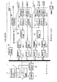
次に、図1を参照して、本発明を適用した情報再生装置の一実施の形態について説明する。図1において、記録制御信号入力部1は、システムコントローラ2に記録処理を指令するとき操作され、再生制御信号入力部3は、システムコントローラ2に再生処理を指令するとき操作される。システムコントローラ2は、記録制御信号入力部1または再生制御信号入力部3からの制御信号に基づいて、デイスクヘッド制御部4、記録処理部5、および再生処理部6を制御し、記録処理および再生処理など所定の処理を実行させるようになされている。
【0014】
記録処理部5は、所定の伝送路を介して伝送されてきた映像信号および音声信号に所定の処理を施し、記録媒体7に供給するようになされている。デイスクヘッド制御部4は、例えば光デイスク、よりなる記録媒体7を制御し、記録処理部5からの信号を、記録媒体7の所定の番地に記録させたり、記録媒体7から所定の信号を読み出させ、再生処理部6に供給させたりする。
【0015】
再生処理部6は、記録媒体7から供給される再生信号を処理し、出力するようになされている。
【0016】
なお、再生処理部6によって再生された映像信号または音声信号を、記録処理部5に入力させるようにすることもできる。
【0017】
記録処理部5は、図2に示すように構成されている。例えば、ビデオテープレコーダ(図示せず)より出力された映像信号、ビデオカメラ(図示せず)から出力された映像信号、またはテレビジョン放送などアンテナ(図示せず)を介して入力される映像信号は、それぞれ映像信号処理装置10、ビデオカメラ信号処理装置11、またはチューナ信号処理装置12に入力され、所定の処理が施されるようになされている。また、DVD(Digital Video Disc)より再生出力された信号または圧縮デイジタル信号は、それぞれDVD方式伸長装置13、または圧縮方式変換装置14に入力され、所定の処理が施されるようになされている。
【0018】
映像信号記録部20の信号切換装置21は、映像信号処理装置10、ビデオカメラ信号処理装置11、およびチューナ信号処理装置12からの信号から、所定の映像信号を選択し、A/D変換装置22に出力するようになされている。A/D変換装置22は、信号切換装置21からの信号をA/D変換し、信号切換装置23に出力するようになされている。信号切換装置23は、A/D変換装置22からの信号、図示せぬ装置から直接入力されたデイジタル映像信号、またはDVD方式伸長装置13の出力する映像信号から、所定の信号を選択し、帯域圧縮装置24および特徴点抽出処理装置25に出力するようになされている。
【0019】
帯域圧縮装置24は、信号切換装置23からの信号を、記録用バッファ27がオーバフロまたはアンダーフロしないように量子化し、例えば、MPEG(Moving Picture Experts Group)またはJPEG(Joint Photographic Experts Group)方式に基づいて、帯域圧縮し、信号切換装置26に出力するようになされている。帯域圧縮装置24はまた、量子化量に対応する情報を特徴点抽出処理装置25に出力している。信号切換装置26は、帯域圧縮装置24からの映像信号と圧縮方式変換装置14からの映像信号から、所定の信号を選択し、記録用バッファ27に出力するようになされている。記録用バッファ27は、信号切換装置26から入手した信号を、データバス29を介して、記録データ処理装置28に供給するようになされている。
【0020】
例えば、テープレコーダ(図示せず)より再生出力された音声信号、マイクロフォン(図示せず)からの音声信号、またはテレビジョン放送などアンテナ(図示せず)を介して入力される音声信号は、それぞれ音声信号処理装置30、マイクロホン信号処理装置31、またはチューナ信号処理装置12に入力され、所定の処理が施されるようになされている。
【0021】
音声信号記録部40の信号切換装置41は、音声信号処理装置30、マイクロホン信号処理装置31、またはチューナ信号処理装置12からの信号から、所定の音声信号を選択し、A/D変換装置42に出力するようになされている。A/D変換装置42は、信号切換装置41からの信号をA/D変換し、信号切換装置43に出力するようになされている。信号切換装置43は、A/D変換装置42からの信号、図示せぬ装置から直接入力されたデイジタル音声信号、またはDVD方式伸長装置13の出力する音声信号から、所定の信号を選択し、帯域圧縮装置44および特徴点抽出処理装置25に出力するようになされている。
【0022】
帯域圧縮装置44は、信号切換装置43からの信号を記録用バッファ47がオーバフロまたはアンダーフロしないように、量子化し、例えば、MPEGオーデイオまたはAC−3方式に基づいて、帯域圧縮し、信号切換装置46に出力するようになされている。帯域圧縮装置44はまた、音声信号の量子化量に対応する信号を特徴点抽出処理装置25に出力している。信号切換装置46は、帯域圧縮装置44からの信号と圧縮方式変換装置14からの音声信号から、所定の信号を選択し、記録用バッファ47に出力するようになされている。記録用バッファ47は、信号切換装置46から入手した信号を、データバス29を介して、記録データ処理装置28に供給するようになされている。
【0023】
デイジタル通信処理装置48は、例えば、インターネットからの情報やデイジタル放送を受信し、所定の処理を施し、特徴点抽出処理装置25に送信するようになされている。
【0024】
特徴点抽出処理装置25は、信号切換装置23、信号切換装置43、帯域圧縮装置24、帯域圧縮装置44、デイジタル信号処理装置48、またはチューナ信号処理装置12からの信号から特徴点に関する情報(例えば、特徴点のアドレス)を抽出し、データバス29を介して、記録データ処理装置28に供給するようになされている。
【0025】
記録データ処理装置28は、映像信号記録部20からの映像信号、音声信号記録部40からの音声信号、および特徴点抽出処理装置25からの特徴点に関する情報を必要に応じて多重化し、さらに記録媒体7に対応する所定の記録フォーマットに変換し、記録媒体7に供給するようになされている。特徴点に関する情報は、例えば、記録媒体7のTOC(Table Of Contents)に記録される。
【0026】
システムコントローラ2は、所定の特徴点に関する情報を特徴点抽出処理装置25に供給し、また映像信号記録部20、記録データ処理装置28、および音声信号記録部40を、デイスクヘッド制御部4とともに制御するようになされている。
【0027】
映像信号および音声信号の特徴点のうち、例えば、プログラム(番組)の開始点、記録開始点、記録一時停止解除点、記録日付変更点、静止画記録開始点に関する情報は、システムコントローラ2から特徴点抽出処理装置25に供給されるようになされている。また、例えば、CM開始点叉は終了点、テロップ挿入点、およびシーン変更点に関する情報は、信号切換装置23または信号切換装置43からの信号から、特徴点抽出処理装置25が抽出するようになされている。また、例えば、ハイライトシーン開始点に関する情報は、デイジタル通信処理装置48からの信号から、特徴点抽出処理装置25が抽出するようになされている。
【0028】
次に、図3に、再生処理部6の構成例を示めす。記録媒体7から供給される信号は、再生データ処理装置50で、例えば、EFM(Eight to Fourteen modulation)復調され、所定の再生フォーマットに対応するように処理されるとともに、映像信号、音声信号および圧縮デイジタル信号に分けられる。再生データ処理装置50からの映像信号は、CH1とCH2の2つのチャンネル分の信号に分けられ、データバス51を介して、映像信号再生部60の再生用バッファ61−1,61−2にそれぞれ入力されるようになされている。
【0029】
再生用バッファ61−1は、再生データ処理装置50から入手した信号を、帯域伸長装置62−1に供給するようになされている。帯域伸長装置62−1は、例えば MPEGまたはJPEG方式に基づいて、再生用バッファ61−1から入力された信号を伸長し、信号生成装置63に出力するようになされている。
【0030】
CH1の再生用バッファ61−1と帯域伸長装置62−1に対して、CH2にもCH2の再生用バッファ61−2と帯域伸長装置62−2が設けられている。
【0031】
信号生成装置63は、帯域伸長装置62−1の出力する信号と帯域伸長装置62−2の出力する信号から、所定の信号を生成し、D/A変換装置64−1とDVD方式圧縮装置65に出力するようになされている。D/A変換装置64−1は、信号生成装置63から入力された信号を、D/A変換し、再生信号出力装置66−1、または図示せぬ機器に出力するようになされている。再生信号出力装置66−1は、D/A変換装置64−1からの信号に、例えば、クロマエンコード処理などを施し、図示せぬ機器に出力する。
【0032】
CH2の帯域伸長装置62−2の出力は、CH1のD/A変換装置64−1および再生信号出力装置66−1に対応するD/A変換装置64−2および再生信号出力装置66−2により、同様の処理が施された後、出力されるようになされている。
【0033】
再生データ処理装置50からの音声信号は、CH1とCH2の2つのチャンネル分の信号に分けられ、データバス51を介して、音声信号再生部70の再生用バッファ71−1,71−2にそれぞれ入力されるようになされている。
【0034】
この音声信号再生部70における再生用バッファ71−1乃至再生信号出力装置76−2の構成は、映像信号再生部60における再生用バッファ61−1乃至再生信号出力装置66−2の構成と、基本的に同様であるので、その説明は省略する。
【0035】
次に、特徴点に関する情報と共に記録媒体7に記録されている映像情報および音声信号が再生される場合の処理手順を、図4に示すフローチャートを参照して説明する。
【0036】
はじめに、ステップS1において、システムコントローラ2は、再生する情報のTOCを読み出す。このTOCの読みだしは、デイスクが装置にはじめて挿入されたとき実行され、読み出されたTOCは、システムコントローラ2の内部のメモリに記憶される。次に、ステップS2において、システムコントローラ2は、再生制御信号入力部3から再生処理を指令する制御信号の入力があるまで待機し、入力があったとき、次に、ステップS3において、システムコントローラ2は、再生処理を指令する制御信号が通常再生に対応するものか、または高速再生に対応するものかを判定する。通常再生とは、ユーザが映像の内容を確認することができる速度(1倍速の速度)で映像を再生する処理を意味し、高速再生とは、通常再生より速い速度で信号を再生することを意味する。従って、高速再生では、ユーザが内容を確認し難い映像が再生される。
【0037】
ステップS3で高速再生に対応する制御信号と判定された場合、ステップS4に進み、ステップS4においては、高速再生処理が実行される。ここでは、システムコントローラ2が、デイスクヘッド制御部4を制御し、通常再生の場合より速い速度で、記録媒体7を回転させ、そこから信号を再生させ、そして再生データ処理装置50、映像信号再生部60、および音声信号再生部70を制御し、記録媒体7から供給された信号を図示せぬデイスプレイに出力表示させる。
【0038】
次に、ステップS5において、システムコントローラ2は、再生制御信号入力部3から、高速再生を解除する制御信号が入力されたかどうかを判定する。高速再生を解除する制御信号の入力が検知されない場合、ステップS6に進む。
【0039】
次に、ステップS6において、システムコントローラ2は、特徴点が接近しているかどうかを判定する。システムコントローラ2は、例えば、特徴点より所定の時間だけ前の所定の位置と、特徴点の間の範囲内に再生点が到達しとき、特徴点が接近しているものと判定する。
【0040】
ステップS6で特徴点が接近していないと判定された場合、ステップS4に戻り、高速再生が継続される。ステップS6で特徴点が接近していると判定された場合、ステップS7に進む。
【0041】
次に、ステップS7において、システムコントローラ2は、デイスクヘッド制御部4を制御し、通常再生より遅い速度で、記録媒体7から信号を再生させ、再生データ処理装置50、映像信号再生部60、および音声信号再生部70を制御し、それを出力表示させる(低速再生させる)。ここで、特徴点が低速で再生されることにより、ユーザは、その特徴点が所望の映像かどうかを容易に認識することができる。例えば、ユーザが、記録されているテレビジョン放送を再生するとき、再生制御信号入力部3を操作し、CM終了点を特徴点として設定すると、各CM終了の直前ごとに低速再生が実行される。
【0042】
なお、ステップS7において、低速再生の代わりに、再生を一時停止しておくこともできる。
【0043】
次に、ステップS8において、システムコントローラ2は、再生制御信号入力部3から高速再生を解除する制御信号が入力されているかどうかを判定する。
【0044】
ステップS8で高速再生が解除されていないと判定された場合、ステップS9に進む。例えば、低速再生されている、あるCM終了以降の映像が所望の映像でない場合、ユーザは、高速再生を解除しない。ステップS9において、システムコントローラ2は、低速再生が所定時間継続されたかどうかを判定する。低速再生の時間が所定時間に達していないとき、ステップS7に戻り、低速再生が継続される。高速再生を解除する制御信号が入力されずに、低速再生が所定時間継続されると、ステップS4に戻り、高速再生が再び実行される。
【0045】
ステップS8で高速再生を解除する制御信号の入力が検知された場合、ステップS10に進み、システムコントローラ2は、制御信号が入力される直前に再生された特徴点を検出し、その特徴点を再生開始点とし、ステップS11において、通常再生を実行させる。
【0046】
ステップS5で高速再生を解除する制御信号の入力が検知された場合、つまり、ユーザが高速再生を解除する所定の操作を行った場合、ステップS12に進む。ステップS12においては、システムコントローラ2は、高速再生解除の制御信号が入力された時点に、最も近い特徴点を検出し、その特徴点が所定の範囲に存在するかどうか判定する。
【0047】
例えば、所定の範囲を記録媒体7のアドレス上の距離とし、システムコントローラ2が、制御信号が入力された時点に再生されていた信号と、特徴点のアドレス上の差を算出し、それが所定のアドレス上の距離を超えているかどうか判定したり、また、所定の範囲を時間とし、高速再生解除の制御信号が入力された時刻と、特徴点が再生されたまたは再生される時刻の差を算出し、それが所定の時間を超えているかどうか判定する。
【0048】
ステップS12で最も近い特徴点が所定の範囲に存在しないと判定された場合、ステップS11に戻り、高速再生解除の制御信号が入力された時点から、通常再生が実行される。ステップS12で最も近い特徴点が所定の範囲に存在すると判定された場合は、ステップS13に進み、ステップS12で検出された特徴点から通常再生が実行される。
【0049】
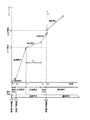
図5乃至図10は、再生される情報の特徴点とユーザの再生制御信号入力部3の操作に対応して、再生モード(通常再生、高速再生、または低速再生)が切り換えられるタイミングを示すタイミングチャートである。次に、これらを参照して、再生モードの切り換えの手順を具体的に説明する。
【0050】
図5は、ユーザが、時刻T1において、記録媒体7の通常再生を開始させ、時刻T2において高速再生を開始させ、時刻T6(特徴点P2が再生される時刻)に高速再生を解除し、それ以降通常再生させるように再生制御信号入力部3を操作した場合のタイミングチャートである。
【0051】
この場合、再生モードは、時刻T1に通常再生モードになり(ステップS11)、時刻T2に高速再生モード(ステップS4)になる。時刻T3に、特徴点(いまの場合、特徴点P1)が接近していると(近傍点であると)判定される(ステップS6)と、高速再生は低速再生モードに切り換えられる。特徴点P1は、ユーザの所望する映像、例えば、所望したCM終了点でないとすると、再生制御信号入力部3は操作されず、時刻T3から時刻T4までの所定時間TLに渡って、低速再生が継続される(ステップS7乃至S9)。
【0052】
時刻T4に、再び高速再生が実行され(ステップS4)、特徴点P2が接近する時刻T5(近傍点が検出されるまで)まで継続される。時刻T5において、高速再生は低速再生に切り換えられる。ユーザが、特徴点P2が所望の映像であると認識すると、時刻T6において、ユーザは、再生制御信号入力部3を操作し、高速再生を解除する(ステップS8)。このことより、低速再生モードが通常再生モードに切り換えられる(ステップS11)。このとき、再生開始点は制御信号が入力された直前に再生された特徴点P2とされる(ステップS10)。
【0053】
図6は、再生制御信号入力部3が図5における場合と同様に操作された場合のタイミングチャートであるが、ステップS6において、特徴点の近傍点ではなく、特徴点そのものに達したか否かが判定される場合のタイミングチャートである。
【0054】
図7は、時刻T4までは図6に示すタイミングチャートの場合と同様の操作が行われ(ただし、ここでは、特徴点P2は存在しないものとする)、時刻T10に、ユーザが、再生制御信号入力部3を操作し、高速再生を解除した場合のタイミングチャートである。
【0055】
時刻T10に、高速再生が解除される(ステップS5)と、その時点から最も近い特徴点(いまの場合、特徴点P1)を検出し、その特徴点P1が、高速再生が解除された時に再生されていた信号PSに対して、所定の範囲L内(いまの場合、記録媒体7のアドレスの差)であるかどうかが判定(ステップS12)される。いまの場合、特徴点P1が所定の範囲L内であるので、特徴点P1から通常再生が実行される(ステップS13,S11)。
【0056】
高速再生解除の制御信号が入力された時点で最も近い特徴点がまだ再生されていない場合でも、図8に示すタイミングチャートのように、解除のタイミングが所定の範囲内であれば、最も近い特徴点P2から通常再生が開始される。
【0057】
図7および図8に示すタイミングチャートでは、最も近い特徴点と高速再生が解除された時点に再生されていた信号のアドレス上の差に基づいて、特徴点が所定の範囲に存在するかどうかが判定されている。これに対して図9に示すタイミングチャートでは、所定の範囲を時間とした場合を示している。
【0058】
図9に示すタイミングチャートにおいては、特徴点P1が、高速再生が解除された時刻T10から、所定時間TM内に再生されていたかどうかが判定される。いまの場合、特徴点P1がその範囲内であるので、特徴点P1から通常再生が開始される。
【0059】
図7乃至図9に示すタイミングチャートは、特徴点に到達した場合、高速再生が低速再生に切り換えられたが、図10に示すようにして、特徴点の映像を静止画として再生する(フリーズする)ようにしてもよい。
【0060】
次に、記録媒体7に記録されている映像信号が、MPEGなどのように、GOP(Group of Picuture)構造を有している場合のタイミングチャートを図11に示す。
【0061】
GOP(n+7)のP5(Pピクチャの5番目のフレーム)に特徴点が存在するGOPn乃至GOP(n+11)で構成されているストリームが高速再生されている場合、時刻TPで高速再生が解除されたとき、最も近い特徴点のGOPのIピクチャから再生が開始される。いまの場合GOP(n+7)のI2(Iピクチャの2番目のフレーム)から通常再生が開始されている。
【0062】
なお、上記したような処理を行うコンピュータプログラムをユーザに提供する提供媒体としては、磁気ディスク、CD-ROM、固体メモリなどの記録媒体の他、ネットワーク、衛星などの通信媒体を利用することができる。
【0063】
【発明の効果】
本発明によれば、特徴点情報に応じた再生モードで情報を再生することができる。
【図面の簡単な説明】
【図1】本発明を適用した情報再生装置の構成例を示すブロック図である。
【図2】記録処理部5の構成例を示すブロック図である。
【図3】再生処理部6の構成例を示すブロック図である。
【図4】記録媒体7に記録されている映像信号が再生される場合の処理手順を説明するフローチャートである。
【図5】再生モードの切り換タイミングを示すタイミングチャートである。
【図6】再生モードの切り換タイミングを示す他のタイミングチャートである。
【図7】再生モードの切り換タイミングを示す他のタイミングチャートである。
【図8】再生モードの切り換タイミングを示す他のタイミングチャートである。
【図9】再生モードの切り換タイミングを示す他のタイミングチャートである。
【図10】再生モードの切り換タイミングを示す他のタイミングチャートである。
【図11】再生モードの切り換タイミングを示す他のタイミングチャートである。
【符号の説明】
1 記録制御信号入力部, 2 システムコントローラ, 3 再生制御信号入力部, 4 デイスクヘッド制御部, 5 記録処理部, 6 再生処理部,7 記録媒体, 10 映像信号処理装置, 11 ビデオカメラ信号処理装置, 12 チューナ信号処理装置, 20 映像信号記録部, 21 信号切換装置, 22 A/D変換装置, 23 信号切換装置, 24 帯域圧縮装置, 25 特徴点抽出処理装置, 26 信号切換装置, 27 記録用バッファ, 28 記録データ処理装置, 30 音声信号処理装置, 31 マイク信号処理装置, 40 音声信号記録部, 41 信号切換装置, 42 A/D変換装置, 43 信号切換装置, 44 帯域圧縮装置, 46 信号切換装置, 47 記録用バッファ, 48 デイジタル通信処理装置, 50 再生データ処理装置, 60 映像信号再生部, 61 再生用バッファ, 62 帯域伸長装置, 63 信号再生装置, 64 D/A変換装置, 65 DVD方法圧縮装置, 66 再生信号出力装置, 70 音声信号再生部, 71 再生用バッファ, 72 帯域伸長装置, 73 信号再生装置, 74D/A変換装置, 76 再生信号出力装置[0001]
BACKGROUND OF THE INVENTION
The present invention relates to an information reproducing apparatus and method, and a providing medium, and in particular, an information reproducing apparatus and method that can reliably search for a feature point by switching a reproduction mode based on a feature point of information to be reproduced. And a providing medium.
[0002]
[Prior art]
A recording / reproducing apparatus that records and reproduces a video signal or an audio signal on a recording medium such as an optical disk or a semiconductor memory is also referred to as a non-linear recording / reproducing apparatus, regardless of the order of recording on the recording medium. So-called random access that allows direct access to any address is possible, and various recording and reproduction processes can be performed.
[0003]
For example, when a user records a television broadcast on a recording medium and then records / reproduces the television broadcast, the user does not perform a high-speed reproduction process in which video is reproduced at a higher speed than usual, and has a feature in the broadcast (hereinafter referred to as a broadcast). (Referred to as a feature point), for example, when searching for the start or end of a commercial message (hereinafter abbreviated as CM), a point where a scene changes, or a point where a telop is inserted, and normal playback of the subsequent video However, the non-linear recording / reproducing apparatus can cope with such processing at high speed and accurately.
[0004]
Nonlinear recording / reproducing apparatuses have been particularly studied in the feature point search method. For example, “Tada, Kijima“ A Study on CM Detection Method for TV Broadcasting ”, Video Information Media Society Technical Report, ITE Technical Report Vol.21, No.23, pp.19-23” includes audio signals and video A method for detecting program material and CM material from the characteristics of signals has been proposed. "Kaneko, Hori," High-speed cut detection from MPEG video using motion vector code amount ", IEICE Technical Report, PRMU96-100 (1996-11), pp.55-62" includes MPEG (Moving Picture Exoerts Group) A method of detecting scene change points at high speed based on the amount of code of a motion vector of a bit stream has been proposed. “Sato, Niikura et al.,“ Effectiveness detection method of cut points and telops from MPEG2 video ”, Shingaku Giho, PRMU96-99 (1996-11), pp.47-54”, from MPEG bitstream, There has been proposed a method for detecting the insertion point of a telop at a high speed by checking a reference field for motion prediction of a P picture, detecting a scene change point at high speed, and checking an appearance frequency of a No MC Coded macrobook. .
[0005]
[Problems to be solved by the invention]
However, the feature points as described above are often short video or audio, and the nonlinear recording / playback apparatus can search for these feature points at high speed, but the user actually operates the recording / playback apparatus, When a desired feature point is searched while being played back at high speed, there is a problem that the user misses the feature point or the operation of the recording / playback apparatus is delayed, so that the desired video or audio cannot be obtained.
[0006]
The present invention has been made in view of such a situation, and enables the user to reliably search for a feature point by switching the playback mode corresponding to the feature point.
[0007]
[Means for Solving the Problems]
The information reproducing apparatus of the present invention is recorded on a recording medium.VideoReproducing means for reproducing according to the reproduction mode, extraction means for extracting feature point information from the signal reproduced from the recording medium, switching means for switching the reproduction mode based on the feature point information,Input means for inputting a release signal for canceling high-speed playback by the playback means when the playback mode is high-speed playback mode, and the switching means plays back the moving image recorded on the recording medium at high-speed playback. When the release signal is input by the input means, the closest feature point from the time when the release signal is input is detected based on the feature point information, and whether the detected feature amount is within the predetermined range When it is determined whether or not it is within the range, the playback mode is switched so that normal playback is performed from a position corresponding to the time point when the release signal is input.
[0008]
The predetermined range may be a distance on a predetermined address or a predetermined time.
[0009]
An information reproduction method of the present invention includes a reproduction step of reproducing a moving image recorded on a recording medium according to a reproduction mode, an extraction step of extracting feature point information from a signal reproduced from the recording medium, and feature point information. A switching step for switching the playback mode, and an input step for inputting a release signal for canceling the high-speed playback in the playback step when the playback mode is the high-speed playback mode. The switching step is a process in the playback step. When playing a video recorded on a recording medium with high-speed playback, when the release signal is input in the input step processing, the feature closest to the point when the release signal is input based on the feature point information When a point is detected and it is determined whether or not the detected feature amount is within a predetermined range, and if it is determined that the detected feature amount is not within the range, a release signal is input As normal reproduction from the position corresponding to the point it is performed, characterized in that switching the playback mode.
[0010]
The program of the providing medium of the present invention includes a reproduction step for reproducing a moving image recorded on a recording medium in accordance with a reproduction mode, an extraction step for extracting feature point information from a signal reproduced from the recording medium, and feature point information. And a switching step for switching the playback mode and an input step for inputting a release signal for canceling the high-speed playback in the playback step when the playback mode is the high-speed playback mode. When playing a video recorded on a recording medium with high-speed playback during processing, when the release signal is input in the input step processing, it is closest to the point when the release signal is input based on the feature point information A feature point is detected, and it is determined whether or not the detected feature value is within a predetermined range. As normal reproduction is performed from the position corresponding to the time of the, and wherein the switching the playback mode.
In the information reproducing apparatus and method of the present invention and the program of the provided medium, the moving image recorded on the recording medium is reproduced according to the reproduction mode, and feature point information is extracted from the signal reproduced from the recording medium, When the playback mode is switched based on the point information, the release signal for canceling the high-speed playback when the playback mode is the high-speed playback mode is input, and the movie recorded on the recording medium is played back at high-speed playback. When the release signal is input, the closest feature point from the time when the release signal is input is detected based on the feature point information, and it is determined whether or not the detected feature amount is within a predetermined range. At the same time, when it is determined that it is not within the range, the playback mode is switched so that normal playback is performed from the position corresponding to the time point when the release signal is input.
[0011]
DETAILED DESCRIPTION OF THE INVENTION
Embodiments of the present invention will be described below, but in order to clarify the correspondence between each means of the invention described in the claims and the following embodiments, in parentheses after each means, The features of the present invention will be described with the corresponding embodiment (however, an example) added. However, of course, this description does not mean that each means is limited to the description.
[0012]
The information reproduction apparatus according to claim 1 extracts reproduction point information from a reproduction unit (for example, the
[0013]
Next, an embodiment of an information reproducing apparatus to which the present invention is applied will be described with reference to FIG. In FIG. 1, a recording control
[0014]
The
[0015]
The
[0016]
Note that the video signal or audio signal reproduced by the
[0017]
The
[0018]
A
[0019]
The
[0020]
For example, an audio signal reproduced and output from a tape recorder (not shown), an audio signal from a microphone (not shown), or an audio signal input via an antenna (not shown) such as a television broadcast, It is input to the audio
[0021]
The
[0022]
The
[0023]
The digital
[0024]
The feature point
[0025]
The recording data processing device 28 multiplexes the video signal from the video signal recording unit 20, the audio signal from the audio signal recording unit 40, and the information on the feature points from the feature point
[0026]
The
[0027]
Among the feature points of the video signal and the audio signal, for example, information on the start point of the program (program), the recording start point, the recording pause release point, the recording date change point, and the still image recording start point is provided from the
[0028]
Next, FIG. 3 shows a configuration example of the
[0029]
The reproduction buffer 61-1 is configured to supply a signal obtained from the reproduction
[0030]
In contrast to CH1 reproduction buffer 61-1 and band expansion device 62-1, CH2 also includes CH2 reproduction buffer 61-2 and band expansion device 62-2.
[0031]
The
[0032]
The output of the CH2 band expansion device 62-2 is output by the D / A conversion device 64-2 and the reproduction signal output device 66-2 corresponding to the CH1 D / A conversion device 64-1 and the reproduction signal output device 66-1. , The same processing is performed and then output.
[0033]
The audio signal from the reproduction
[0034]
The configuration of the reproduction buffer 71-1 to the reproduction signal output device 76-2 in the audio signal reproduction unit 70 is the same as the configuration of the reproduction buffer 61-1 to the reproduction signal output device 66-2 in the video signal reproduction unit 60. Therefore, the description thereof is omitted.
[0035]
Next, a processing procedure when the video information and the audio signal recorded on the
[0036]
First, in step S1, the
[0037]
If it is determined in step S3 that the control signal corresponds to high-speed playback, the process proceeds to step S4, and high-speed playback processing is executed in step S4. Here, the
[0038]
Next, in step S <b> 5, the
[0039]
Next, in step S6, the
[0040]
If it is determined in step S6 that the feature points are not approaching, the process returns to step S4 and high-speed playback is continued. If it is determined in step S6 that the feature points are approaching, the process proceeds to step S7.
[0041]
Next, in step S7, the
[0042]
In step S7, the playback can be paused instead of the low speed playback.
[0043]
Next, in step S <b> 8, the
[0044]
If it is determined in step S8 that the high-speed playback has not been canceled, the process proceeds to step S9. For example, when the video that has been played back at low speed and the video after the end of a certain CM is not the desired video, the user does not cancel the high-speed playback. In step S9, the
[0045]
When the input of the control signal for canceling the high-speed playback is detected in step S8, the process proceeds to step S10, and the
[0046]
If an input of a control signal for canceling high-speed playback is detected in step S5, that is, if the user performs a predetermined operation for canceling high-speed playback, the process proceeds to step S12. In step S12, the
[0047]
For example, a predetermined range is set as the distance on the address of the
[0048]
If it is determined in step S12 that the closest feature point does not exist within the predetermined range, the process returns to step S11, and normal playback is executed from the time when the control signal for canceling high-speed playback is input. If it is determined in step S12 that the closest feature point exists in the predetermined range, the process proceeds to step S13, and normal reproduction is executed from the feature point detected in step S12.
[0049]
5 to 10 show timings at which the playback mode (normal playback, high speed playback, or low speed playback) is switched in accordance with the feature points of the information to be played back and the operation of the playback control
[0050]
FIG. 5 shows that the user starts normal playback of the
[0051]
In this case, the playback mode is the normal playback mode at time T1 (step S11) and the high speed playback mode (step S4) at time T2. If it is determined at time T3 that the feature point (in this case, feature point P1) is approaching (is a nearby point) (step S6), the high-speed playback is switched to the low-speed playback mode. If the feature point P1 is not a video desired by the user, for example, a desired CM end point, the reproduction control
[0052]
At time T4, high-speed playback is executed again (step S4), and continues until time T5 when the feature point P2 approaches (until a nearby point is detected). At time T5, the high speed reproduction is switched to the low speed reproduction. When the user recognizes that the feature point P2 is a desired video, at time T6, the user operates the playback control
[0053]
FIG. 6 is a timing chart when the reproduction control
[0054]
In FIG. 7, the same operation as in the timing chart shown in FIG. 6 is performed until time T4 (here, the feature point P2 does not exist), and at time T10, the user makes a reproduction control signal. It is a timing chart at the time of operating the
[0055]
When high-speed playback is canceled at time T10 (step S5), the closest feature point (in this case, feature point P1) from that point is detected, and the feature point P1 is played back when high-speed playback is canceled. Signal PSOn the other hand, it is determined whether it is within a predetermined range L (in this case, the difference in the address of the recording medium 7) (step S12). In this case, since the feature point P1 is within the predetermined range L, normal reproduction is executed from the feature point P1 (steps S13 and S11).
[0056]
Even when the closest feature point at the time when the high-speed playback release control signal is input has not yet been played back, as long as the release timing is within a predetermined range as shown in the timing chart of FIG. Normal reproduction starts from the point P2.
[0057]
In the timing charts shown in FIGS. 7 and 8, whether or not a feature point exists within a predetermined range is determined based on a difference in address between the closest feature point and a signal reproduced at the time when high-speed reproduction is canceled. It has been judged. On the other hand, the timing chart shown in FIG. 9 shows a case where the predetermined range is time.
[0058]
In the timing chart shown in FIG. 9, the feature point P1 is a predetermined time T from the time T10 when the high-speed playback is canceled.MIt is determined whether or not it has been played back. In this case, since the feature point P1 is within the range, normal reproduction is started from the feature point P1.
[0059]
In the timing charts shown in FIGS. 7 to 9, when the feature point is reached, the high speed playback is switched to the low speed playback. However, as shown in FIG. 10, the video of the feature point is played back as a still image (freezes). You may do it.
[0060]
Next, FIG. 11 shows a timing chart when the video signal recorded on the
[0061]
When a stream composed of GOPn to GOP (n + 11) having feature points in P5 of GOP (n + 7) (the fifth frame of the P picture) is played back at high speed, the time TPWhen the high-speed playback is canceled, the playback starts from the I picture of the GOP of the closest feature point. In this case, normal reproduction is started from I2 of GOP (n + 7) (the second frame of the I picture).
[0062]
As a providing medium for providing a user with a computer program for performing the processing as described above, a communication medium such as a network or a satellite can be used in addition to a recording medium such as a magnetic disk, a CD-ROM, or a solid-state memory. .
[0063]
【The invention's effect】
According to the present invention, information can be reproduced in a reproduction mode corresponding to feature point information.
[Brief description of the drawings]
FIG. 1 is a block diagram showing a configuration example of an information reproducing apparatus to which the present invention is applied.
FIG. 2 is a block diagram illustrating a configuration example of a
FIG. 3 is a block diagram illustrating a configuration example of a
FIG. 4 is a flowchart illustrating a processing procedure when a video signal recorded on a
FIG. 5 is a timing chart showing playback mode switching timing.
FIG. 6 is another timing chart showing playback mode switching timing.
FIG. 7 is another timing chart showing playback mode switching timing.
FIG. 8 is another timing chart showing playback mode switching timing.
FIG. 9 is another timing chart showing playback mode switching timing.
FIG. 10 is another timing chart showing playback mode switching timing.
FIG. 11 is another timing chart showing playback mode switching timing.
[Explanation of symbols]
DESCRIPTION OF
Claims (4)
前記記録媒体から再生された信号から特徴点情報を抽出する抽出手段と、
前記特徴点情報に基づいて、再生モードを切り換える切換手段と、
前記再生モードが高速再生モードであるときの前記再生手段による高速再生を解除する解除信号を入力する入力手段と
を備え、
前記切換手段は、前記再生手段が高速再生で前記記録媒体に記録されている動画を再生しているときに、前記入力手段により前記解除信号が入力されたとき、前記特徴点情報に基づいて前記解除信号が入力された時点から最も近い特徴点を検出し、検出した特徴量が所定の範囲内のものか否かを判定するとともに、範囲内のものではないと判定した場合、解除信号が入力された時点に応じた位置からの通常再生が行われるように、再生モードを切り換える
ことを特徴とする情報再生装置。 Playback means for playing back a moving image recorded on a recording medium according to a playback mode;
Extraction means for extracting feature point information from a signal reproduced from the recording medium;
Switching means for switching the reproduction mode based on the feature point information;
Input means for inputting a release signal for releasing high-speed reproduction by the reproduction means when the reproduction mode is high-speed reproduction mode;
With
The switching means, when the reproduction means is reproducing a moving image recorded on the recording medium at high speed reproduction, when the release signal is inputted by the input means, based on the feature point information The closest feature point from the time when the release signal is input is detected, it is determined whether or not the detected feature quantity is within the predetermined range, and if it is determined that it is not within the range, the release signal is input The playback mode is switched so that normal playback from the position corresponding to the point in time is performed.
An information reproducing apparatus characterized by that.
前記記録媒体から再生された信号から特徴点情報を抽出する抽出ステップと、 An extraction step of extracting feature point information from a signal reproduced from the recording medium;
前記特徴点情報に基づいて、再生モードを切り換える切換ステップと、 A switching step for switching the reproduction mode based on the feature point information;
前記再生モードが高速再生モードであるときの前記再生ステップでの高速再生を解除する解除信号を入力する入力ステップと An input step for inputting a release signal for canceling high-speed playback in the playback step when the playback mode is high-speed playback mode;
を含み、 Including
前記切換ステップは、前記再生ステップでの処理で高速再生で前記記録媒体に記録されている動画を再生しているときに、前記入力ステップの処理で前記解除信号が入力されたとき、前記特徴点情報に基づいて前記解除信号が入力された時点から最も近い特徴点を検出し、検出した特徴量が所定の範囲内のものか否かを判定するとともに、範囲内のものではないと判定した場合、解除信号が入力された時点に応じた位置からの通常再生が行われるように、再生モードを切り換える The switching step is characterized in that, when the moving image recorded on the recording medium is played back at a high speed by the processing in the playback step, and the release signal is input in the processing in the input step, the feature point When the closest feature point from the time when the release signal is input is detected based on the information, and it is determined whether or not the detected feature amount is within a predetermined range, and is determined not to be within the range Switching the playback mode so that normal playback from the position corresponding to the point in time when the release signal is input
ことを特徴とする情報再生方法。 An information reproduction method characterized by the above.
記録媒体に記録されている動画を再生モードに応じて再生する再生ステップと、 A playback step of playing back the moving image recorded on the recording medium according to the playback mode;
前記記録媒体から再生された信号から特徴点情報を抽出する抽出ステップと、 An extraction step of extracting feature point information from a signal reproduced from the recording medium;
前記特徴点情報に基づいて、再生モードを切り換える切換ステップと、 A switching step for switching the reproduction mode based on the feature point information;
前記再生モードが高速再生モードであるときの前記再生ステップでの高速再生を解除する解除信号を入力する入力ステップと An input step for inputting a release signal for canceling high-speed playback in the playback step when the playback mode is high-speed playback mode;
を含み、 Including
前記切換ステップは、前記再生ステップでの処理で高速再生で前記記録媒体に記録されている動画を再生しているときに、前記入力ステップの処理で前記解除信号が入力されたとき、前記特徴点情報に基づいて前記解除信号が入力された時点から最も近い特徴点を検出し、検出した特徴量が所定の範囲内のものか否かを判定するとともに、範囲内のものではないと判定した場合、解除信号が入力された時点に応じた位置からの通常再生が行われるように、再生モードを切り換える The switching step is characterized in that, when the moving image recorded on the recording medium is played back at a high speed by the processing in the playback step, and the release signal is input in the processing in the input step, the feature point When the closest feature point from the time when the release signal is input is detected based on the information, and it is determined whether or not the detected feature amount is within a predetermined range, and is determined not to be within the range Switching the playback mode so that normal playback from the position corresponding to the point in time when the release signal is input
プログラムを提供することを特徴とする提供媒体。 A providing medium characterized by providing a program.
Priority Applications (1)
| Application Number | Priority Date | Filing Date | Title |
|---|---|---|---|
| JP02048798A JP3794146B2 (en) | 1998-01-16 | 1998-01-16 | Information reproducing apparatus and method, and providing medium |
Applications Claiming Priority (1)
| Application Number | Priority Date | Filing Date | Title |
|---|---|---|---|
| JP02048798A JP3794146B2 (en) | 1998-01-16 | 1998-01-16 | Information reproducing apparatus and method, and providing medium |
Publications (2)
| Publication Number | Publication Date |
|---|---|
| JPH11203845A JPH11203845A (en) | 1999-07-30 |
| JP3794146B2 true JP3794146B2 (en) | 2006-07-05 |
Family
ID=12028512
Family Applications (1)
| Application Number | Title | Priority Date | Filing Date |
|---|---|---|---|
| JP02048798A Expired - Fee Related JP3794146B2 (en) | 1998-01-16 | 1998-01-16 | Information reproducing apparatus and method, and providing medium |
Country Status (1)
| Country | Link |
|---|---|
| JP (1) | JP3794146B2 (en) |
Families Citing this family (4)
| Publication number | Priority date | Publication date | Assignee | Title |
|---|---|---|---|---|
| KR20010009273A (en) * | 1999-07-08 | 2001-02-05 | 김영환 | Moving Picture Indexing and Retrieving Method using Moving Activity Description Method |
| JP4575124B2 (en) * | 2004-11-29 | 2010-11-04 | オリンパス株式会社 | Image display device |
| JP4547293B2 (en) * | 2005-04-04 | 2010-09-22 | オリンパス株式会社 | Image display device |
| JP2008301968A (en) * | 2007-06-06 | 2008-12-18 | Olympus Medical Systems Corp | Endoscopic image processing apparatus |
-
1998
- 1998-01-16 JP JP02048798A patent/JP3794146B2/en not_active Expired - Fee Related
Also Published As
| Publication number | Publication date |
|---|---|
| JPH11203845A (en) | 1999-07-30 |
Similar Documents
| Publication | Publication Date | Title |
|---|---|---|
| JP4737572B2 (en) | Data recording medium | |
| JP3491365B2 (en) | Encoded data decoding method and decoding device | |
| US8290353B2 (en) | Data processing device and method | |
| US5978543A (en) | Video disk recorder which compresses video data and inserts addresses of intra-frames into the user data area of the headers of the intra-frames | |
| JP3526414B2 (en) | Information recording / reproducing method and information recording / reproducing device | |
| JP3701051B2 (en) | Information recording apparatus and information reproducing apparatus | |
| US7084908B2 (en) | Image signal recording apparatus with controlled recording of main, preceding and succeeding moving image signals | |
| EP1339233B1 (en) | Audio/video data recording/reproducing device and method, and audio/video data reproducing device and method | |
| KR100777856B1 (en) | Image recording apparatus and method, image reproducing apparatus and method, and recording medium | |
| US20030219041A1 (en) | Method for recording location information of broadcasting signals, and a broadcasting signal receiving device and transmitting device capable of recording location information of broadcasting signals | |
| JP3794146B2 (en) | Information reproducing apparatus and method, and providing medium | |
| JP2002290921A (en) | Signal processing system, signal output device, signal receiver, signal processing method, signal output method and signal receiving method | |
| JP2000078531A (en) | Method and system for editing audio data | |
| JP2005303336A (en) | Video signal recording apparatus and video signal reproducing apparatus | |
| JP2004280994A (en) | Data creation method and data recorder | |
| US6285982B1 (en) | Sound decompressing apparatus providing improved sound quality during special reproducing such as forward search reproducing and reverse search reproducing | |
| JP2000278643A (en) | Data conversion device | |
| JP3890655B2 (en) | Digital signal reproduction method and apparatus | |
| JP2000011545A (en) | Recorder and recording method | |
| US20060078276A1 (en) | Optical disk recording and reproducing apparatus | |
| WO2003065715A1 (en) | Audio/video data recording/reproduction apparatus, system, and method, recording medium recorded by them, audio/video data reproduction apparatus, and data structure | |
| JP2002033712A (en) | Packet processor and packet output method therefor | |
| JPH1079917A (en) | Device for recording and recording data | |
| JP4196475B2 (en) | Reproduction apparatus and method, and recording and / or reproduction apparatus and method | |
| JPH11134814A (en) | Audio recording medium and audio reproducing device |
Legal Events
| Date | Code | Title | Description |
|---|---|---|---|
| A521 | Written amendment |
Free format text: JAPANESE INTERMEDIATE CODE: A523 Effective date: 20050117 |
|
| A621 | Written request for application examination |
Free format text: JAPANESE INTERMEDIATE CODE: A621 Effective date: 20050117 |
|
| A131 | Notification of reasons for refusal |
Free format text: JAPANESE INTERMEDIATE CODE: A131 Effective date: 20051216 |
|
| A521 | Written amendment |
Free format text: JAPANESE INTERMEDIATE CODE: A523 Effective date: 20060214 |
|
| A521 | Written amendment |
Free format text: JAPANESE INTERMEDIATE CODE: A523 Effective date: 20060214 |
|
| TRDD | Decision of grant or rejection written | ||
| A01 | Written decision to grant a patent or to grant a registration (utility model) |
Free format text: JAPANESE INTERMEDIATE CODE: A01 Effective date: 20060322 |
|
| A61 | First payment of annual fees (during grant procedure) |
Free format text: JAPANESE INTERMEDIATE CODE: A61 Effective date: 20060404 |
|
| FPAY | Renewal fee payment (event date is renewal date of database) |
Free format text: PAYMENT UNTIL: 20090421 Year of fee payment: 3 |
|
| FPAY | Renewal fee payment (event date is renewal date of database) |
Free format text: PAYMENT UNTIL: 20100421 Year of fee payment: 4 |
|
| FPAY | Renewal fee payment (event date is renewal date of database) |
Free format text: PAYMENT UNTIL: 20100421 Year of fee payment: 4 |
|
| FPAY | Renewal fee payment (event date is renewal date of database) |
Free format text: PAYMENT UNTIL: 20110421 Year of fee payment: 5 |
|
| FPAY | Renewal fee payment (event date is renewal date of database) |
Free format text: PAYMENT UNTIL: 20110421 Year of fee payment: 5 |
|
| FPAY | Renewal fee payment (event date is renewal date of database) |
Free format text: PAYMENT UNTIL: 20120421 Year of fee payment: 6 |
|
| FPAY | Renewal fee payment (event date is renewal date of database) |
Free format text: PAYMENT UNTIL: 20120421 Year of fee payment: 6 |
|
| FPAY | Renewal fee payment (event date is renewal date of database) |
Free format text: PAYMENT UNTIL: 20130421 Year of fee payment: 7 |
|
| LAPS | Cancellation because of no payment of annual fees |