JP3793893B2 - Bag mouth seal device - Google Patents
Bag mouth seal device Download PDFInfo
- Publication number
- JP3793893B2 JP3793893B2 JP2002116792A JP2002116792A JP3793893B2 JP 3793893 B2 JP3793893 B2 JP 3793893B2 JP 2002116792 A JP2002116792 A JP 2002116792A JP 2002116792 A JP2002116792 A JP 2002116792A JP 3793893 B2 JP3793893 B2 JP 3793893B2
- Authority
- JP
- Japan
- Prior art keywords
- bag
- bag mouth
- mouth portion
- sealing
- sealing device
- Prior art date
- Legal status (The legal status is an assumption and is not a legal conclusion. Google has not performed a legal analysis and makes no representation as to the accuracy of the status listed.)
- Expired - Lifetime
Links
Images


Landscapes
- Closing Of Containers (AREA)
- Package Closures (AREA)
Description
【0001】
【発明の属する技術分野】
本発明は、物品を収容した袋の袋口部をシールする袋口部シール装置に関するものである。
【0002】
【従来の技術】
物品を収容した袋の袋口部をシールする装置に関して、次のようなものが従来から採用されている。例えば、一対のエンドレス状ベルトの間に袋口部を挟んで搬送しつつ、該袋口部を加熱ローラ間に通過させることでシールしたり、あるいは加熱板を用いてベルト自体を加熱することで、挟まれている袋口部をシールする技術がある。
【0003】
【発明が解決しようとする課題】
袋に収容した物品が嵩のあるものの場合、該袋の袋口部は筒状になるため、前記のベルトに筒状の袋口部を挟んだ際に皺を生じてしまう。従って、そのままシールされるとシール部に皺が残り、見栄えが劣ると共に、シールが不完全となるおそれがある。
【0004】
【発明の目的】
この発明は、前述した従来の技術に内在している前記課題に鑑み、これを好適に解決するべく提案されたものであって、袋の袋口部に良好なシールを施し得る袋口部シール装置を提供することを目的とする。
【0005】
【課題を解決するための手段】
前述した課題を克服し、所期の目的を好適に達成するため、本発明に係る袋口部シール装置は、
袋に物品を収容する袋詰機から搬出される袋の袋胴部が載置され、該搬出方向と交差する方向に向けて袋を、その開口縁が袋移送方向に沿う姿勢で移送する移送手段と、
前記移送手段の速度と略同速度で走行し、前記袋の袋口部を載置保持して袋移送方向の下流側に向けて移送する袋口搬送手段と、
前記袋口搬送手段で移送される袋口部に対して昇降動可能に設定され、袋口部を吸着して上昇することで該袋口部を開口する吸着部材を備え、該吸着部材が袋口搬送手段とによって袋口部を挟持する状態では、袋口搬送手段と略同速度で袋移送方向の下流側に向けて移動するよう設定される開口手段と、
前記開口手段により開口された袋の袋口部内に進入して袋移送方向に沿って開くことで、該袋口部を扁平状態にする一対の拡開部材を備え、該拡開部材は扁平状態の袋口部を拡開状態としたもとで、前記袋口搬送手段と略同速度で袋移送方向の下流側に向けて移動するよう設定される整形手段と、
前記袋口搬送手段の速度と略同速度で走行し、前記整形手段で扁平状態とされる袋口部を、前記袋口搬送手段における載置保持位置より袋胴部側で支持して袋移送方向の下流側に向けて移送する保持手段と、
前記保持手段により扁平状態で移送される袋口部をシールするシール手段とから構成したことを特徴とする。
【0006】
【発明の実施の形態】
次に、本発明に係る袋口部シール装置につき、好適な実施例を挙げて、添付図面を参照しながら以下説明する。なお、本発明は以下の実施例に限定されるものではない。
【0007】
図1に示す袋口部シール装置(以下 単にシール装置と云う)10は、一方に開口部(袋口)を有する袋11に、例えば食パン等の物品12を袋詰めする袋詰機(図示せず)の後段に配置される。そして、袋詰機で物品12が収容された袋11は、図2に示す如く、その袋口が上流側を指向する姿勢で搬出コンベヤ13によって搬出され、この袋11がシール装置10に受け渡されるよう構成される。なお、袋11の物品12が収容されている部分を袋胴部11aと指称し、該袋胴部11aから開口部側に向けて延在する部分を袋口部11bと指称する。
【0008】
【移送手段】
前記シール装置10は、前記搬出コンベヤ13から受け渡された袋11を、その袋口が側方を向く横向き姿勢で該コンベヤ13による袋11の搬出方向と略直角に交差する方向に向けて略水平に移送する移送手段14を備える。この移送手段14は、袋11における袋胴部11aが載置される略水平なテーブル15の下方を循環走行する無端チェン16に所定間隔で取付けた多数の押送体17からなる押送コンベヤで構成され、無端チェン16の上側の走路においてテーブル15から上方に突出する押送体17により、該テーブル15に載置された袋胴部11aを押して下流側に移送するよう構成される。このとき袋11は、前記袋口部11bが押送コンベヤ14の一側部(後側)外方に延出すると共に、その開口縁が袋移送方向に沿う姿勢で移送されるようになっている。なお、押送コンベヤ14による袋移送方向と水平に直交する方向を前後方向と指称し、袋口部11bが袋胴部11aから延出する向きを後側と指称する。
【0009】
前記押送コンベヤ14で移送される袋11における袋口部11bが延出するコンベヤ後側に、該袋口部11bを開口する開口手段18、袋口部11bを扁平状態に整形する整形手段19、袋口部11bをシールするシール手段20および袋口部11bを結束する結束手段21が、押送コンベヤ14での袋移送方向上流側から下流側に順に配置されている。
【0010】
【袋口搬送手段】
前記押送コンベヤ14の後側に位置する装置機枠25に調節用機体26が上下動可能に配設され(図8参照)、調節用機体26は、該機体26と螺合するネジ軸とスプロケット等からなる調節機構27を図示しないモータにより回転することで上下位置が調節され、これら調節用機体26と調節機構27とから位置調節手段を構成するようになっている。この調節用機体26に一体的に配設された第1フレーム28に、袋移送方向の前後に離間して一対のプーリ29,29が回転可能に枢支され、両プーリ29,29間に、走行方向に所定間隔で吸引孔22aが多数穿設された袋口搬送手段としての第1の吸着ベルト22が巻掛けられている。この第1の吸着ベルト22において袋口部11bを移送する上側の走路は、図1または図2に示す如く、前記搬出コンベヤ13から押送コンベヤ14への袋11の受け渡し位置の直後から下流側のシール手段20の直前までの間に亘って延在して、押送コンベヤ14の袋移送方向に沿って該コンベヤ14の速度と略同速度で走行するよう設定される。
【0011】
また、前記第1の吸着ベルト22における上側の走路(押送コンベヤ14で移送される袋11と同じ向きに走行する走路)の下面側には、第1フレーム28に配設されて図示しない吸引源に接続する第1吸引チャンバー30が接し、押送コンベヤ14で移送される袋11における袋口部11bの下側側部を、第1吸引チャンバー30上面の透孔(図示せず)および前記吸引孔22aを介して作用する吸引力によって略水平なベルト上面に吸着保持した状態で下流側に移送するよう構成される。なお、第1吸引チャンバー30の略水平な最上面に沿って走行する第1の吸着ベルト22の上面高さは、前記袋11に収容されている物品12の高さの略1/2の位置あるいはこれより僅かに低い位置となるよう、該吸引チャンバー30の配設位置が設定されている(図1参照)。
【0012】
【開口手段】
前記開口手段18は、前記第1の吸着ベルト22に載置保持された状態で移送される袋口部11bの移送路の上方に設けられた吸着部材としての吸盤23およびその回転手段24から構成され、第1の吸着ベルト22で移送される袋口部11bの上側側部を吸着した吸盤23が上昇することによって、該袋口部11bを開口するよう構成される。
【0013】
前記調節用機体26に一体的に配設された支持フレーム31の前側(押送コンベヤ側)に離間して取付部材32が複数のステー70を介して配設され、支持フレーム31と取付部材32との間に、図4に示す如く、袋移送方向の前後に離間して一対の回転軸33が回転可能に架設されている。一方の回転軸33の支持フレーム31から後方に延出する軸端が、図示しないモータに連結されると共に、両回転軸33,33はチェン−スプロケット等からなる連繋機構34を介して一体的に回転するよう構成される。図3および図4に示す如く、各回転軸33の取付部材32から前方に延出する軸端に円盤状の回転体35が一体回転するよう夫々配設されると共に、両回転体35,35には、その回転中心から偏心した位置にホルダ36の対応する端部が夫々回動可能に枢支されており、両回転体35,35が同一方向に回転することで、ホルダ36は姿勢を維持したまま略鉛直面上で円運動を行なうよう構成される。すなわち、実施例では、回転軸33,33、連繋機構34および回転体35,35から回転手段24が構成される。なお、前記ホルダ36は、前記押送コンベヤ14の押送体17が1ピッチ移動する間に1回転するよう回転制御される。
【0014】
前記ホルダ36には、図5に示す如く、エアシリンダ37が倒立姿勢で配設されると共に、そのピストンロッド37aに支持部材38が連結される。この支持部材38には、袋移送方向の前後に離間して一対の吸盤23,23が前記第1の吸着ベルト22と対向するよう下向きに配設され、この吸盤23,23に接続する吸引源(図示せず)による吸引作用により、前記袋11の袋口部11bにおける上側側部を吸着保持するよう構成される。各吸盤23は支持部材38に対して上下動可能に配設されると共に、常にはバネ39によって下方に向けて付勢されており、下側を第1の吸着ベルト22で吸着保持されている袋口部11bに上側から当接した際には上方に退避し得るよう構成される。
【0015】
前記エアシリンダ37は、ホルダ36が最上位位置から最下位位置へ回転移動する際には、該吸盤23,23をホルダ36に対して離間する下動位置まで下動させると共に、最下位位置から最上位位置へ回転移動する際には、該吸盤23,23をホルダ36に対して近接する上動位置まで上動させるよう付勢制御される。また下動位置の吸盤23,23は、ホルダ36が最下位位置に到来する前の所定位置から、第1の吸着ベルト22とで前記袋口部11bを挟持する(袋口部11bに当接する)よう位置設定されており、このときに該吸盤23,23がバネ39で付勢された状態で袋口部11bに密着するよう構成される。そして、ホルダ36が最下位位置に到来したときに袋口部11bの上側側部を吸着保持した吸盤23,23が、エアシリンダ37により上動位置まで上動すると共に回転手段24により上方に向けて回転移動することで、該吸盤23,23が第1の吸着ベルト22から離間するよう上昇して吸着保持した袋口部11bが開口されるよう構成されている。
【0016】
なお、前記回転手段24には、前記支持フレーム31の後側において、前記モータに連結された一方の回転軸33に不等速回転機構62が設けられ、ホルダ36は不等速回転するよう構成される。またホルダ36は、概ね前記吸盤23,23が袋11の袋口部11bを第1の吸着ベルト22とで挟持する前述の所定位置から最下位位置を越えた所定位置までは、その袋移送方向の速度が第1の吸着ベルト22および前記押送コンベア14の速度と略同一となるよう設定される。すなわち、吸盤23,23は、押送コンベヤ14で移送される袋11と同じ向き(袋移装方向の下流側)に略同速度で移動しつつ袋口部11bに近接・離間し、近接した際に袋口部11bを吸着して離間する際に吸着した袋口部11bを開口するよう構成されている。また、前記吸盤23,23による吸引は、該吸盤23,23が袋口部11bに密着するまでの適宜時点で開始され、概ねホルダ36が最下位位置を越えた前述の所定位置に至るまでの間であって、後述する拡開部材40,40が開口された袋口部内に挿入された後の適宜時点で解除されるよう設定してある。
【0017】
【整形手段】
前記整形手段19は、一対の拡開部材40,40と、該拡開部材40,40を開閉する開閉機構41および拡開部材40,40を袋移送方向に沿う方向に走行させる移動機構42とから基本的に構成される。
【0018】
前記調節用機体26の前側に離間して取付フレーム43が配設され、該取付フレーム43および調節用機体26の対向面間に、図6に示す如く、袋移送方向の前後に離間して一対の回転軸44,44が夫々回転可能に枢支されている。また各回転軸44には、軸方向に離間して2つのスプロケット45,45が夫々一体回転可能に配設され、袋移送方向の前後で対をなすスプロケット45,45に無端チェン46が夫々巻掛けられて移動機構42が構成される。そして、一対の無端チェン46,46間に、平行な2本のロッドで構成される複数のガイド材対47が、走行方向に前記押送コンベヤ14における押送体17の取付間隔と同一の間隔で架設され、図示しないモータによって無端チェン46,46を走行駆動することで、ガイド材対47が、前記押送コンベヤ14および第1の吸着ベルト22の速度と略同速度で循環走行するよう構成される。なお、実施例の2本のロッドからなるガイド材対47に代えて、一本のレール状のものを採用し得る。
【0019】
前記ガイド材対47における上下の移動域の間には、図7に示す如く、上側ガイドレール48と下側ガイドレール49とが配設され、各ガイド材対47に前後方向に移動可能に配設されている移動体50が、両ガイドレール48,49に案内されることでガイド材対47に対して前後動するよう構成されている。下側ガイドレール49には、図2に示す如く、移動体50をガイド材対47に沿って前進した後に所定長さだけ袋移送方向(押送コンベヤ14で移送される袋11と同じ向き)に移動させ、その後に後退させる案内部49aが形成してある。また各移動体50には、上下のガイドレール48,49に沿って移動する姿勢において、袋移送方向の前後に離間して板状を呈する一対の拡開部材40,40が水平回動可能に配設され、その前端部を袋移送方向に沿う方向に相互に近接・離間(開閉)し得るよう構成される。前記各ガイド材対47には、両拡開部材40,40の間に位置固定状態で臨むカム51が配設され、該カム51の袋移送方向前後両側に形成されたカム面51a,51aに、両拡開部材40,40の後端部に枢支されたカムフォロワ52,52が転動可能に当接するようになっている。なお、各拡開部材40は、移動体50との間に張設されたバネ53によって、カムフォロワ52を常に対応するカム面51aに当接するよう付勢されている。また下方移動域(袋口部11bを拡開する整形動作域)を移動する拡開部材40,40は、図7に示す如く、袋11に収容されている物品12の高さの略1/2の位置に対応するよう位置決め設定される。
【0020】
前記カム51のカム面51a,51aは、前記移動体50が下側ガイドレール49の案内部49aに案内されてガイド材対47に対して前進移動する際に、カムフォロワ52,52を介して案内される一対の拡開部材40,40の前端部が相互に離間し(開き)、該移動体50が後退移動する際には前端部が相互に近接する(閉じる)よう設定される。また拡開部材40,40が前進移動する位置は、前記開口手段18により袋口部11bが開口される位置と対応するように、前記案内部49aの形成位置が設定されている。すなわち拡開部材40,40は、その下方移動域において、押送コンベア14および第1の吸着ベルト22の速度と略同速度で袋11と同じ向き(袋移送方向の下流側)に移動しつつ、開口されている袋口部内に進入して袋移送方向に沿って開くことで、袋口部11bを略水平な扁平状態に整形し、その後に閉じて袋口部外に退出するよう構成される。なお実施例では、前述したガイド材対47、移動体50、下側ガイドレール49およびカム51から開閉機構41が構成される。
【0021】
【シール手段】
前記シール手段20は、前記調節用機体26に配設されて、上下に対向する一対の加熱ローラ54,54を有し、両加熱ローラ54,54の当接位置は、前記押送コンベヤ14で移送される袋11に収容されている物品12の高さの略1/2の位置に対応するよう位置決め設定されている(図8参照)。すなわち、前記整形手段19により扁平状態に整形された袋口部11bが、両加熱ローラ54,54間を通過することで、該袋口部11bに帯状のシールを施すよう構成される。なお、両加熱ローラ54,54の回転速度は、前記押送コンベア14の速度と略同一に設定されている。また前記シール手段20は、前記調節用機体26に対して前後方向(袋移送方向と水平に直交する方向)に移動可能に配設され、該シール手段20(加熱ローラ54,54)の位置を、図示しない位置調節手段によって前後方向に移動調節することで、袋口部11bにおけるその開口縁からのシール位置を変更し得るよう構成される。なお、この位置調節手段としては、例えば調節用機体26に設けられたネジ軸をシール手段20における適宜の部材と螺合し、該ネジ軸を回転させることでシール手段20を位置調節する構成を採用し得るが、その他各種の機構を用いることができる。
【0022】
【保持手段】
図1に示す如く、前記拡開部材40,40の下方移動域に近接した下方に、該拡開部材40,40により扁平状態にされた袋口部11bを、前記第1の吸着ベルト22による袋口部11bの載置保持位置より袋胴部側において下側から吸着保持する保持手段55が配設される。この保持手段55は、図2に示す如く、前記押送コンベヤ14に沿って配設された保持用の第2の吸着ベルト57を有し、第2の吸着ベルト57の最上側の走路(押送コンベヤ14で移送される袋11と同じ向きに走行する走路である袋口部吸着域)において、扁平化された袋口部11bをその状態のまま略水平なベルト上面に吸着保持するよう構成される。すなわち、前記調節用機体26に一体的に配設された第2フレーム58(図8参照)に回転可能に配設されて袋移送方向の前後に離間する複数のプーリ59に第2の吸着ベルト57が循環走行するよう巻掛けられる。第2の吸着ベルト57は、前記押送コンベア14および第1の吸着ベルト22の速度と略同速度で循環走行すると共に、該第2の吸着ベルト57の袋口部吸着域と、前記シール手段20における両加熱ローラ54,54が当接する部位とのレベルが略一致するよう設定される。
【0023】
前記第2の吸着ベルト57には、その走行方向に所定間隔で吸引孔57aが多数穿設されている。また、前記第2の吸着ベルト57における袋口部吸着域の下面側には、第2フレーム58に配設されて図示しない吸引源に接続する第2吸引チャンバー60が接し、押送コンベヤ14で移送される袋11における袋口部11bを、第2吸引チャンバー60上面の透孔60a(図2参照)および各吸引孔57aを介して作用する吸引力によって略水平なベルト上面に吸着保持した状態で下流側に移送するよう構成される。なお、図2に示す如く、第2の吸着ベルト57と第2吸引チャンバー60とは、シール手段20の加熱ローラ54,54と干渉しない位置を走行すると共に、その下流端部は、加熱ローラ54,54の配設位置より下流側に設定され、シールの際にも袋口部11bを第2の吸着ベルト57で扁平状態に吸着保持するよう構成される。
【0024】
前記第2の吸着ベルト57で吸着保持される扁平状態とされた袋口部11bの上方に、前記調節用機体26に配設されて該袋口部11bの上側を案内する上側ガイド61が袋口部吸着域に対応する範囲で配設され、扁平状態の袋口部11bが不用意に開かないよう構成してある。すなわち、前記拡開部材40,40により扁平状態とされた袋口部11bは、その上側を上側ガイド61で、その下側を第2の吸着ベルト57で保持された状態で、シール手段20の加熱ローラ54,54によりシールされるよう構成される(図8参照)。
【0025】
【結束手段】
前記シール手段20の下流側に、公知の結束手段21が配設され、前記押送コンベヤ14で移送される袋11のシールが施された袋口部11bに、該袋口部11bを挟持手段で挟持しつつ結束具(何れも図示せず)を装着して結束するよう構成されている。
【0026】
【実施例の作用】
次に、実施例に係るシール装置の作用につき説明する。前記袋詰機の搬出コンベヤ13により搬出される袋11は、その袋口を搬出方向の上流側に指向する姿勢で前記テーブル15上に受け渡されて袋胴部11aが載置される。この袋11は、前記押送コンベヤ14の押送体17により、その開口縁を袋移送方向に沿わせた姿勢で下流側に向けて移送される。このとき、押送コンベヤ14の後側外方に延出する袋口部11bは、袋11に収容されている物品12の高さの略1/2の位置あるいはこれより僅かに低い位置において、図2に示す如く、前記第1の吸着ベルト22に下側から吸着保持された状態で、該コンベヤ14と略同速度で下流側に移送される。
【0027】
前記押送コンベヤ14で移送される袋11が所定位置に到来したタイミングで、前記開口手段18のエアシリンダ37により下動位置に保持されている吸盤23,23が、前記回転手段24による回転移動により袋口部11bに向けて上方から近接して密着し、前記第1の吸着ベルト22との間で袋口部11bを挟持した状態で下流側に略同速度で移動する。そして、前記ホルダ36が最下位位置に到来したときにエアシリンダ37により吸盤23,23が上動位置まで上動されると共に、回転手段24によりホルダ36が最上位位置に向けて回転移動することで、該吸盤23,23は第1の吸着ベルト22から離間する。このとき、袋口部11bにおける下側のフィルムは第1の吸着ベルト22に吸着保持されているから、吸盤23,23に吸着保持されている上側のフィルムが上方に持上げられることで、袋口部11bは開口される。
【0028】
前記開口手段18により袋口部11bが開口されるタイミングで、前記移動機構42により下方移動域を袋11と同じ向きに移動されている整形手段19の拡開部材40,40が、前記開閉機構41によって前進移動して袋口部内に進入し、次いで前進移動しつつ両拡開部材40,40が袋移送方向に沿う方向に開くことで、図2に示す如く、該袋口部11bは扁平状態に整形される。なお、拡開部材40,40が袋口部内に進入した後のタイミングで、前記吸盤23,23による吸引は解除され、吸盤23,23から袋口部11bは解放される。
【0029】
前記拡開部材40,40により扁平状態とされた袋口部11bは、前記第1の吸着ベルト22および保持手段55の第2の吸着ベルト57により下側から吸着保持された状態で下流側に移送される。そして前記シール手段20の配設位置近傍まで袋11が移送されると、該袋11と共に同じ向きに移動していた前記拡開部材40,40は開開機構41の作用によって閉じると共に袋口部外に退出する。また各ベルト22,57で下側が吸着保持されている袋口部11bは、その上側が前記上側ガイド61で保持されて該袋口部11bが不用意に開くのは防止され、扁平状態を保持したままシール手段20に向けて移送される。
【0030】
前記扁平状態の袋口部11bは、前記シール手段20における一対の加熱ローラ54,54の間を通過し、このときに帯状のシールが施される。前記保持手段55における第2の吸着ベルト57はシール手段20の下流側まで延在し、そのシール時にも袋口部11bを下側から吸着保持しているから、当該シールが良好に行なわれる。
【0031】
前記押送コンベヤ14で下流側に移送される袋11のシールが施された袋口部11bは、挟持手段により挟持された状態で、前記結束手段21により結束具が装着され、該袋口部11bは結束具により結束される。
【0032】
実施例に係るシール装置10では、物品12が収容された袋11の袋口部11bにシールを施す前に、一対の拡開部材40,40により扁平状態とするから、物品12が嵩のあるものの場合であっても良好なシールを施すことができる。しかも、袋口部11bを開口手段18により予め開口しておくから、拡開部材40を袋口部11b内へ確実に挿入し得る。また、前記吸盤23,23および拡開部材40,40は、押送コンベヤ14で移送される袋11と同じ向きに略同速度で移動しつつ開口および扁平化の各処理を行なうので、袋11の連続移送が可能で、高速運転に対応することができる。
【0033】
なお、前記袋11に収容される物品12の高さが変更された場合は、前記調節機構27を作動して調節用機体26を位置調節することで、該調節用機体26に配設されている前記第1吸引チャンバー30、第1の吸着ベルト22のプーリ29や開口手段18の回転手段24(吸盤23,23)、整形手段19、保持手段55の第2吸引チャンバー60や第2の吸着ベルト57のプーリ59およびシール手段20は一体的に調節され、押送コンベヤ14で移送される袋11に収容された物品12(袋口)の上下方向中央位置に対応させることが容易にできる。また、前記シール手段20を位置調節手段により前後に位置調節することで、袋口部11bの開口縁からのシール位置を任意に変更することも可能である。
【0034】
【別実施例】
図9および図10は、袋口部シール装置の別実施例を示すものであり、その基本的な構成は前述した実施例と同じであるので、異なる部分についてのみ説明すると共に、既出の同一部材には同じ符号を付すものとする。
【0035】
【物品検出センサ】
別実施例の袋口部シール装置71では、前記開口手段18の吸盤23,23による袋口部11bの吸着位置より上流側に、前記押送コンベヤ14の各押送体17によって所定間隔毎に物品12が収容された袋11が移送されてきているか否かを検出(有無の検出)する光電式の物品検出センサ63が配設されている。そして、この物品検出センサ63によって袋11が検出されなかった際には、前記開口手段18による袋口部11bの開口作動、すなわち吸盤23,23の吸引作用、および前記エアシリンダ37による吸盤23,23の下動が休止されるよう設定してある。これにより、袋11を押送していない空の状態の押送体17が吸着位置に到来する際には、開口手段18の不必要な作動が抑制される。
【0036】
【保持手段】
別実施例の保持手段65は、前述した実施例のように袋口部11bを下側から吸着保持する第2の吸着ベルト57に代えて、該袋口部11bを上下で挟んで移送する一対の無端状支持ベルト66,67で構成される。すなわち保持手段65は、前記整形手段19の拡開部材40,40により扁平状態とされた前記袋口部11bを載置して移送する下側支持部材としての下側支持ベルト67と、袋口部11bを上方から支持する上側支持部材としての上側支持ベルト66とを有し、両支持ベルト66,67により袋口部11bを挟んだ状態で前記シール手段20に向けて移送するよう構成されている。また上下の各支持ベルト66,67は、何れも前記押送コンベア14および第1の吸着ベルト22の速度と略同速度で袋移送方向に沿って循環走行するよう設定される。なお、前記両支持ベルト66,67による袋口部11bの挟み位置は、図10に示す如く、前記拡開部材40,40の拡開時における最も前進した位置(袋胴部側に最も近接した位置)での袋胴部11a側を向く先端部より更に袋胴部側の位置に設定されて、該拡開部材40,40と上側支持ベルト66とが干渉しないように構成してある。
【0037】
前記下側支持ベルト67は、図9に示す如く、前記拡開部材40,40の下方移動域(整形動作域)より上流側からシール手段20を越える位置までに亘り、上側の走路が水平に延在するよう設定される。これに対して上側支持ベルト66は、拡開部材40,40の下方移動域における下流側からシール手段20を越える位置までに亘り、下側の走路が下側支持ベルト67に沿って水平に延在するよう設定されており、シール手段20でシールされる際の袋口部11bを上下の支持ベルト66,67で挟んだ状態で移送することで、シールを良好に行なわせるようになっている。別実施例の保持手段65では、上下の支持ベルト66,67は袋口部11bを扁平状態で維持できる程度に軽く挟んで支持しているが、所定圧で確実に挟持するようにしてもよい。
【0038】
なお、前記下側支持ベルト67の上側水平走路と前記シール手段20における両加熱ローラ54,54の当接部位とのレベルが、略一致するよう設定される。また、上側支持ベルト66と下側支持ベルト67とからなる保持手段65は、前記物品12の高さに対応して、第1の吸着ベルト22(袋口搬送手段)、開口手段18、整形手段19およびシール手段20と一体的に高さ方向の位置調節が行なわれるよう構成してある。
【0039】
【異常検出センサ】
ここで、前記袋詰機から袋口部シール装置71に搬出された袋詰品において、前記袋11の袋胴部11aに収容されているべき物品12の一部が、袋口部11bに存在していると、下流側において開口手段18や整形手段19等での処理に際し、これら手段18,19が該物品12を傷めたり、あるいは該物品12を開口手段18や整形手段19等で噛込んで、これら手段18,19が故障するおそれがある。そこで別実施例では、袋口部11bに前記物品12が存在しているか否かを検出する異常検出センサ64が設けられている。この異常検出センサ64は、前記保持手段65の上流側で、該保持手段65を構成する下側支持ベルト67の上方において、物品12が当接可能な位置に臨んで傾動可能な検出片64aを備え、該検出片64aに上流側から物品12が当接して傾動されたときに異常検出して、このときには当該シール装置71自体の動作を停止制御するよう設定される。すなわち、物品12が存在する袋口部11bが、開口手段18や整形手段19等で処理されて故障の原因となるのを未然に防止することができるようになっている。
【0040】
【脱気手段】
前記上側支持ベルト66の上流側端より僅かに上流側に、前記袋口部11bに向けて上方から圧縮エアを吹付けて該袋口部11b内のエアを排出するための脱気手段としてのエア吹付けノズル68が配設されている。なお、エア吹付けノズル68は、前記整形手段19の拡開部材40,40により扁平状態とされている袋口部11bと袋胴部11aとの間に臨んでフィルムが上下に離間している袋口部11bに向けて圧縮エアを吹付けるよう位置決めされ、袋口部11bの全体におけるエア抜きを行なうことで、袋11を物品12に沿った形状となるようにすると共に、前記保持手段65における上下の支持ベルト66,67で挟まれる部位を略扁平状として両ベルト66,67間に袋口部11bが円滑に導入されるようになっている。
【0041】
【巻込み防止手段】
前記シール手段20における上側の加熱ローラ54のシール面は凹凸形状に設定され、シール面が平面に設定された下側の加熱ローラ54とによって袋口部11bを所定圧力で挟持して回転することで、該袋口部11bに施すシール部にシール目を付与するよう構成されている。この場合、シール面が凹凸形状とされた上側の加熱ローラ54にシールされた袋口部11bが付着した状態で、該上側加熱ローラ54に巻込まれて上方に捲れ上がるおそれがある。これを防止するため別実施例では、両加熱ローラ54,54による袋口部11bの挟持位置を挟んで袋移送方向の上流側から下流側に亘る所定範囲で、該袋口部11bを袋移送方向に沿って案内する巻込み防止手段69が設けられている。
【0042】
前記巻込み防止手段69は、前記加熱ローラ54,54の挟持位置より後側において、前記保持手段65により移送される袋口部11bの上方位置を該保持手段65の速度と略同速度で循環走行する無端ベルト70を有し、該ベルト70の下側の水平走行路が、前記挟持位置を挟んで袋移送方向の上流側から下流側に亘る所定範囲で延在するよう設定される。そして、この水平走行路を下流側に向けて走行する無端ベルト70が、前記袋口部11bの上面を支持案内するよう構成される。すなわち、両加熱ローラ54,54により袋口部11bがシールされる際には、その開口縁側の上面が無端ベルト70により支持案内されることで、該袋口部11bの上方への捲れ上がりは防止され、良好なシールが達成されるようになっている。またこの巻込み防止手段69は、物品12の高さに対応してシール手段20と一体的に高さ方向の位置調節が行なわれるよう構成される。
【0043】
なお、前記袋口部11bの巻込みのおそれがある凹凸形状のシール面に設定された一方の加熱ローラ54が上側に設けられている別実施例では、前記無端ベルト70を袋口部11bの移送路の上方に設けたが、下側に設けられる加熱ローラ54のシール面が凹凸形状に設定されている場合は、袋口部11bの移送路の下方に無端ベルト70を配設する構成が採用される。また、必要に応じて無端ベルト70を上下に設けて袋口部11bを上下の無端ベルト70,70で挟んだ状態で下流側に向けて移送しつつ案内するものであってもよい。但し、上下の両加熱ローラ54,54のシール面が何れも平面に設定されている場合等では、巻込み防止手段69を省略することができる。
【0044】
そして別実施例の袋口部シール装置71では、前述した実施例のシール装置10と同様の作用を奏するのに加えて、袋11を押送していない空の状態の押送体17が、前記開口手段18の吸着位置に到来する場合は、これを前記物品検出センサ63で検出して、開口手段18における吸盤23,23の吸引や下動を休止させることができ、該開口手段18がムダな動きをするのを抑制し得る。また、前記袋口部11bに物品12が存在することを、前記異常検出センサ64が検出した際には、シール装置71の動作を停止制御することで、下流側での開口手段18、整形手段19および保持手段65(上下の支持ベルト66,67)等において物品12を傷めたり、該物品12を噛込むことによるこれら手段18,19,65の故障は未然に防止される。
【0045】
更に、前記整形手段19の拡開部材40,40により扁平状態とされている袋口部11bにおける袋胴部11a側の部分に前記エア吹付けノズル68から圧縮エアを吹付けることで、袋口部11b内のエア抜きが達成される。これにより、袋口部11bにおける前記上下の支持ベルト66,67で挟まれる部位が略扁平状となり、両支持ベルト66,67間に袋口部11bが円滑に導入される。また、袋口部11bの全体のエア抜きが好適に達成されるから、タイトな包装体が得られる。
【0046】
更にまた、前記シール手段20による袋口部11bのシールに際して、そのシール位置より袋胴部11a側の袋口部11bは上下の支持ベルト66,67で挟んだ状態で移送されるから、シールを良好に行なうことができる。しかも、シール面が凹凸形状とされた上側の加熱ローラ54と対応して、該袋口部11bのシール位置より開口縁側の上面を前記無端ベルト70で案内支持するから、袋口部11bが上側の加熱ローラ54に巻込まれるのを防止することができ、より良好なシールを達成し得る。
【0047】
【変更例】
実施例では、袋を水平に移送するよう構成したが、袋の袋口が斜め上方を向く姿勢となるように、装置全体を傾けて配置してもよい。また、移送手段としては、実施例の押送コンベアに代えてベルトコンベアを採用することができる。更に、袋口搬送手段に関しては、吸着ベルトに限定されるものでなく、袋口部を粘着保持し得る粘着ベルト等、袋口部を位置ずれすることなく保持して走行し得る、その他各種方式を採用し得る。
【0048】
前記シール手段に関しては、実施例の加熱ローラに代えて、シールバーを上下に対向するよう設け、これらシールバーが袋口部に対する挟持状態を保って袋と共に移動する、いわゆるボックスモーションをするようにしてもよい。また、吸盤の配設数は、実施例のように2つである必要はなく、袋口部における袋移送方向の長さに応じて1つまたは3つ以上の適宜数に設定すればよい。なお、開口手段に関しては、吸盤の回転手段は実施例の構成に限定されるものでなく、例えば所定の配置で配設したプーリやスプロケットに巻掛けたベルトやチェンに吸盤を配設し、該ベルトやチェンの走行に伴って吸盤が袋口部に対して近接・離間移動(昇降動)するよう構成してもよい。また、吸盤を昇降動する手段と、袋移送方向に沿って前後動する手段とを別々に設けることで、実施例と同様の動作をさせる構成を採用し得る。更に、整形手段の開閉機構や移動機構に関しても、実施例の構成に限定されず、流体圧シリンダにより拡開部材を開閉したり袋移送方向に沿って往復移動する構成を適宜に採用し得る。更にまた、袋口搬送手段、開口手段、整形手段、保持手段およびシール手段は、夫々が袋口部の位置に対応して位置調節し得る位置調節手段を備えていてもよい。
【0049】
なお、別実施例に採用した物品検出センサ、異常検出センサ、脱気手段および巻込み脱止手段は、実施例の装置に適宜に採用することができる。また巻込み防止手段は、無端ベルトに代えて複数の自由回転可能なローラを袋移送方向に並列に配置する構成等、袋口部の加熱ローラへの巻込みを防止し得るものであれば、その他の構成を採用し得る。
【0050】
【発明の効果】
以上に説明した如く、本発明の請求項1に係る袋口部シール装置によれば、袋口部を拡開部材で扁平状態にしたもとでシールを施し得るから、良好なシールが得られる。また拡開部材は、移送される袋に対し同じ向きに移動しつつ袋口部を扁平状態にするから、袋の連続移送が可能で高速運転に対応できる。
【0051】
請求項2に係る袋口部シール装置によれば、吸着部材と対向して配設した吸着ベルトにより袋口部を吸着保持するよう構成したので、該袋口部の開口を確実に行なうことができる。また請求項3に係る袋口部シール装置によれば、袋に収容される物品の大きさに応じて、袋口搬送手段、開口手段、整形手段、保持手段およびシール手段を位置調節し得るから、常に物品の中央位置に対応して袋口部を扁平状態にしたもとでシールを施すことができ、良好なシールが得られる。更に、請求項4に係る袋口部シール装置によれば、シール手段による袋口部に対するシール位置を調節し得るので、袋口部の開口縁からのシール位置を任意に変更することも可能である。更にまた、請求項5に係る袋口部シール装置によれば、単に袋口部を結束しただけのものに比べて異物の混入を防ぐ効果が顕著となる。
【0052】
請求項6に係る袋口部シール装置によれば、シール手段でシールされる際の袋口部を一対の支持部材で挟んだ状態で移送するから、該シール手段でのシールを良好に行なうことができる。請求項7に係る袋口部シール装置によれば、上側支持部材の上流側において袋口部に圧縮エアを吹付けてエア抜きを行なうことで、一対の支持部材間への袋口部の円滑な導入が達成される。請求項8に係る袋口部シール装置によれば、開口手段の吸着位置より上流側で物品が収容された袋の有無を検出する物品検出センサが袋を検出しないときには、開口手段の作動を休止してムダな動きを抑制し得る。請求項9に係る袋口部シール装置によれば、シール手段でシールされる際の袋口部を巻込み防止手段で袋移送方向に沿って案内することで、加熱ローラへの袋口部の巻込みを防止することができる。更に、請求項10に係る袋口部シール装置によれば、袋口部に物品が存在することを異常検出センサが検出した際には、袋口部シール装置の動作を停止するので、下流側での各手段等において物品を傷めることや、該物品を噛込むことによるこれら手段の故障は未然に防止される。
【図面の簡単な説明】
【図1】本発明の好適な実施例に係る袋口部シール装置を示す概略正面図である。
【図2】実施例に係る袋口部シール装置を示す概略平面図である。
【図3】実施例に係る開口手段の要部を示す概略正面図である。
【図4】実施例に係る開口手段の要部を示す概略平面図である。
【図5】実施例に係る開口手段の要部を示す概略側面図である。
【図6】実施例に係る整形手段の要部を示す概略平面図である。
【図7】実施例に係る押送コンベヤ、整形手段および保持手段の要部を示す概略側面図である。
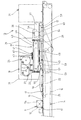
【図8】実施例に係る押送コンベヤ、保持手段およびシール手段の要部を示す概略側面図である。
【図9】本発明の好適な別実施例に係る袋口部シール装置を示す概略正面図である。
【図10】別実施例に係る袋口部シール装置を示す概略平面図である。
【符号の説明】
10 袋口部シール装置
11 袋
11a 袋胴部
11b 袋口部
12 物品
14 押送コンベヤ(移送手段)
18 開口手段
19 整形手段
20 シール手段
21 結束手段
22 第1の吸着ベルト(袋口搬送手段)
23 吸盤(吸着部材)
26 調節用機体(位置調節手段)
27 調節機構(位置調節手段)
40 拡開部材
55 保持手段
63 物品検出センサ
64 異常検出センサ
65 保持手段
66 上側支持ベルト(上側支持部材)
67 下側支持ベルト(下側支持部材)
68 エア吹付けノズル(脱気手段)
69 巻込み防止手段
71 袋口部シール装置[0001]
BACKGROUND OF THE INVENTION
The present invention relates to a bag mouth portion sealing device for sealing a bag mouth portion of a bag containing an article.
[0002]
[Prior art]
Conventionally, the following devices have been adopted as a device for sealing a bag mouth portion of a bag containing articles. For example, while transporting the bag mouth portion between a pair of endless belts, the bag mouth portion is sealed by passing between heating rollers, or the belt itself is heated by using a heating plate. There is a technology for sealing the sandwiched bag mouth.
[0003]
[Problems to be solved by the invention]
In the case where the article contained in the bag is bulky, the bag mouth portion of the bag has a cylindrical shape, and thus wrinkles are generated when the cylindrical bag mouth portion is sandwiched between the belts. Therefore, if it is sealed as it is, wrinkles remain in the seal portion, the appearance is inferior, and the seal may be incomplete.
[0004]
OBJECT OF THE INVENTION
In view of the above-mentioned problems inherent in the prior art described above, the present invention has been proposed to suitably solve this problem, and a bag mouth seal that can provide a good seal to the bag mouth of the bag. An object is to provide an apparatus.
[0005]
[Means for Solving the Problems]
In order to overcome the above-described problems and achieve the desired purpose suitably, the bag mouth portion sealing device according to the present invention is:
Transfer that transports the bag in a posture in which the opening edge is along the bag transfer direction in a direction crossing the carry-out direction, where the bag body portion of the bag that is unloaded from the bagging machine that stores articles in the bag is placed. Means,
Traveling at substantially the same speed as the speed of the transfer means, placing and holding the bag mouth portion of the bag and transferring the bag mouth toward the downstream side in the bag transport direction;
It is set so as to be movable up and down with respect to the bag mouth portion transferred by the bag mouth conveying means, and includes an adsorbing member that opens the bag mouth portion by adsorbing and raising the bag mouth portion, and the adsorbing member is a bag In a state where the bag mouth portion is sandwiched by the mouth transporting means, opening means set to move toward the downstream side in the bag transport direction at substantially the same speed as the bag mouth transporting means,
A pair of expanding members that flatten the bag mouth portion by entering the bag mouth portion of the bag opened by the opening means and opening along the bag transport direction, the expanding member being in a flat state The shaping means set to move toward the downstream side in the bag transfer direction at substantially the same speed as the bag mouth conveying means, with the bag mouth portion in an expanded state,
Said Bag mouth transport means Run at approximately the same speed as The bag mouth portion that is flattened by the shaping means, In the bag mouth conveying means Oke The bag body side from the mounting holding position so Holding means for supporting and transferring toward the downstream side in the bag transfer direction;
It is characterized by comprising sealing means for sealing the bag mouth portion transferred in a flat state by the holding means.
[0006]
DETAILED DESCRIPTION OF THE INVENTION
Next, a bag mouth portion sealing device according to the present invention will be described below with reference to the accompanying drawings by way of preferred embodiments. In addition, this invention is not limited to a following example.
[0007]
A bag mouth portion sealing device (hereinafter simply referred to as a “sealing device”) 10 shown in FIG. Z) is placed in the latter stage. Then, as shown in FIG. 2, the
[0008]
[Transport]
The
[0009]
An opening means 18 for opening the
[0010]
[Pouch mouth transport means]
An
[0011]
Further, on the lower surface side of the upper runway (the runway running in the same direction as the
[0012]
[Opening means]
The
[0013]
A mounting
[0014]
As shown in FIG. 5, the
[0015]
When the
[0016]
The rotating means 24 is provided with a non-constant
[0017]
[Shaping means]
The shaping means 19 includes a pair of expanding
[0018]
A mounting
[0019]
As shown in FIG. 7, an
[0020]
The cam surfaces 51a and 51a of the
[0021]
[Seal means]
The sealing means 20 is disposed on the
[0022]
[Holding means]
As shown in FIG. 1, a
[0023]
The
[0024]
An
[0025]
[Bundling means]
A known bundling means 21 is disposed downstream of the sealing means 20, and the
[0026]
[Effect of the embodiment]
Next, the operation of the sealing device according to the embodiment will be described. The
[0027]
At the timing when the
[0028]
When the opening means 18 opens the
[0029]
The
[0030]
The
[0031]
The
[0032]
In the
[0033]
When the height of the
[0034]
[Another example]
9 and 10 show another embodiment of the bag mouth portion sealing device, and the basic configuration is the same as that of the above-described embodiment. Are given the same reference numerals.
[0035]
[Article detection sensor]
In the bag mouth
[0036]
[Holding means]
The holding means 65 of another embodiment replaces the
[0037]
As shown in FIG. 9, the
[0038]
Note that the levels of the upper horizontal running path of the
[0039]
[Abnormality detection sensor]
Here, in the bagged product carried out from the bagging machine to the bag mouth
[0040]
[Deaeration means]
As deaeration means for blowing compressed air from above toward the
[0041]
[Entrainment prevention means]
The sealing surface of the
[0042]
The
[0043]
In another embodiment in which one
[0044]
In addition, in the bag mouth
[0045]
Further, by blowing compressed air from the
[0046]
Furthermore, when the
[0047]
[Example of change]
In the embodiment, the bag is transported horizontally, but the entire apparatus may be tilted so that the bag mouth of the bag faces obliquely upward. Moreover, as a transfer means, it can replace with the push conveyor of an Example, and can employ | adopt a belt conveyor. Further, the bag mouth transporting means is not limited to the suction belt, and other various systems that can run while holding the bag mouth portion without being displaced, such as an adhesive belt that can hold the bag mouth portion by sticking. Can be adopted.
[0048]
As for the sealing means, instead of the heating roller of the embodiment, a sealing bar is provided so as to face the top and bottom, and the sealing bar moves with the bag while maintaining a clamping state with respect to the bag mouth portion, so-called box motion is performed. May be. The number of suction cups need not be two as in the embodiment, and may be set to one or three or more appropriate numbers according to the length of the bag mouth portion in the bag transfer direction. As for the opening means, the rotation means of the suction cup is not limited to the configuration of the embodiment. For example, the suction cup is disposed on a belt or chain wound around a pulley or sprocket disposed in a predetermined arrangement, The suction cup may be configured to move toward and away from the bag mouth (up and down movement) as the belt or chain travels. Moreover, the structure which carries out the operation | movement similar to an Example can be employ | adopted by providing separately the means to raise / lower a suction cup, and the means to move back and forth along a bag transfer direction. Further, the opening / closing mechanism and the moving mechanism of the shaping means are not limited to the configuration of the embodiment, and a configuration in which the expanding member is opened / closed by the fluid pressure cylinder or reciprocated along the bag transfer direction can be appropriately employed. Furthermore, the bag mouth conveying means, the opening means, the shaping means, the holding means, and the sealing means may each include a position adjusting means that can adjust the position corresponding to the position of the bag mouth portion.
[0049]
In addition, the article detection sensor, the abnormality detection sensor, the deaeration unit, and the roll-in prevention unit that are employed in another embodiment can be appropriately employed in the apparatus of the embodiment. In addition, the winding prevention means may be configured to prevent winding of the bag mouth portion to the heating roller, such as a configuration in which a plurality of freely rotatable rollers are arranged in parallel in the bag transfer direction instead of the endless belt, Other configurations may be employed.
[0050]
【The invention's effect】
As described above, according to the bag mouth portion sealing device according to
[0051]
According to the bag mouth portion sealing device according to claim 2, since the bag mouth portion is sucked and held by the suction belt disposed opposite to the suction member, the opening of the bag mouth portion can be reliably performed. it can. Further, according to the bag mouth portion sealing device according to claim 3, the position of the bag mouth conveying means, the opening means, the shaping means, the holding means and the sealing means can be adjusted according to the size of the article accommodated in the bag. Since the bag mouth portion is always in a flat state corresponding to the center position of the article, a good seal can be obtained. Furthermore, according to the bag mouth portion sealing device according to the fourth aspect, the sealing position with respect to the bag mouth portion by the sealing means can be adjusted, so that the seal position from the opening edge of the bag mouth portion can be arbitrarily changed. is there. Furthermore, according to the bag mouth portion sealing device according to the fifth aspect, the effect of preventing the entry of foreign matters becomes more prominent than that in which the bag mouth portion is simply bound.
[0052]
According to the bag mouth portion sealing device according to claim 6, since the bag mouth portion when being sealed by the sealing means is transported in a state sandwiched between the pair of support members, the sealing means can be well sealed. Can do. According to the bag mouth portion sealing device according to claim 7, the bag mouth portion between the pair of support members can be smoothly smoothed by blowing compressed air to the bag mouth portion on the upstream side of the upper support member. Implementation is achieved. According to the bag mouth portion sealing device of the eighth aspect, when the article detection sensor for detecting the presence / absence of the bag containing the article upstream from the suction position of the opening means does not detect the bag, the operation of the opening means is suspended. And it can suppress wasteful movement. According to the bag mouth portion sealing device of the ninth aspect, the bag mouth portion when being sealed by the sealing means is guided along the bag transfer direction by the entrainment preventing means, so that the bag mouth portion to the heating roller is Entrainment can be prevented. Further, according to the bag mouth portion sealing device according to the tenth aspect, when the abnormality detection sensor detects that an article is present in the bag mouth portion, the operation of the bag mouth portion sealing device is stopped. It is possible to prevent a failure of these means by damaging the article in each means or by biting the article.
[Brief description of the drawings]
FIG. 1 is a schematic front view showing a bag mouth portion sealing apparatus according to a preferred embodiment of the present invention.
FIG. 2 is a schematic plan view showing a bag mouth portion sealing apparatus according to an embodiment.
FIG. 3 is a schematic front view showing a main part of the opening means according to the embodiment.
FIG. 4 is a schematic plan view showing a main part of the opening means according to the embodiment.
FIG. 5 is a schematic side view showing a main part of the opening means according to the embodiment.
FIG. 6 is a schematic plan view showing the main part of the shaping means according to the embodiment.
FIG. 7 is a schematic side view illustrating the main parts of a push conveyor, a shaping unit, and a holding unit according to the embodiment.
FIG. 8 is a schematic side view showing the main parts of a push conveyor, holding means and sealing means according to an embodiment.
FIG. 9 is a schematic front view showing a bag mouth portion sealing apparatus according to another preferred embodiment of the present invention.
FIG. 10 is a schematic plan view showing a bag mouth portion sealing device according to another embodiment.
[Explanation of symbols]
10 Bag mouth seal device
11 bags
11a Bag body
11b Bag mouth
12 Goods
14 Pushing conveyor (transfer means)
18 Opening means
19 Shaping means
20 Sealing means
21 Bundling means
22 First suction belt (bag mouth conveying means)
23 Suction cup (Suction member)
26 Airframe for adjustment (position adjustment means)
27 Adjustment mechanism (position adjustment means)
40 Expanding member
55 Holding means
63 Article detection sensor
64 Abnormality detection sensor
65 Holding means
66 Upper support belt (upper support member)
67 Lower support belt (lower support member)
68 Air spray nozzle (deaeration means)
69 Means for preventing entrainment
71 Bag mouth seal device
Claims (10)
前記移送手段(14)の速度と略同速度で走行し、前記袋(11)の袋口部(11b)を載置保持して袋移送方向の下流側に向けて移送する袋口搬送手段(22)と、
前記袋口搬送手段(22)で移送される袋口部(11b)に対して昇降動可能に設定され、袋口部(11b)を吸着して上昇することで該袋口部(11b)を開口する吸着部材(23)を備え、該吸着部材(23)が袋口搬送手段(22)とによって袋口部(11b)を挟持する状態では、袋口搬送手段(22)と略同速度で袋移送方向の下流側に向けて移動するよう設定される開口手段(18)と、
前記開口手段(18)により開口された袋(11)の袋口部内に進入して袋移送方向に沿って開くことで、該袋口部(11b)を扁平状態にする一対の拡開部材(40,40)を備え、該拡開部材(40,40)は扁平状態の袋口部(11b)を拡開状態としたもとで、前記袋口搬送手段(22)と略同速度で袋移送方向の下流側に向けて移動するよう設定される整形手段(19)と、
前記袋口搬送手段 (22)の速度と略同速度で走行し、前記整形手段 (19) で扁平状態とされる袋口部 (11b) を、前記袋口搬送手段(22)における載置保持位置より袋胴部(11a)側で支持して袋移送方向の下流側に向けて移送する保持手段(55,65)と、
前記保持手段(55,65)により扁平状態で移送される袋口部(11b)をシールするシール手段(20)とから構成した
ことを特徴とする袋口部シール装置。The bag body (11a) of the bag (11) unloaded from the bagging machine that houses the article (12) is placed in the bag (11), and the bag (11) is directed toward the direction intersecting the unloading direction. A transfer means (14) for transferring the opening edge in a posture along the bag transfer direction; and
Traveling at substantially the same speed as the speed of the transfer means (14), the bag mouth transport means for transporting the bag mouth portion (11b) of the bag (11) toward the downstream side in the bag transport direction by placing and holding the bag mouth portion (11b). 22) and
The bag mouth portion (11b) transferred by the bag mouth transport means (22) is set to be movable up and down, and the bag mouth portion (11b) is lifted by adsorbing the bag mouth portion (11b). In the state where the adsorbing member (23) is opened and the adsorbing member (23) sandwiches the bag mouth portion (11b) by the bag mouth conveying means (22), the bag mouth conveying means (22) is at substantially the same speed. Opening means (18) set to move toward the downstream side in the bag transfer direction; and
A pair of expanding members that enter the bag mouth portion of the bag (11) opened by the opening means (18) and open the bag mouth portion (11b) in a flat state by opening along the bag transfer direction ( 40, 40), and the expanding member (40, 40) has the bag mouth portion (11b) in a flat state in an expanded state, and the bag is opened at substantially the same speed as the bag mouth conveying means (22). Shaping means (19) set to move towards the downstream side in the transfer direction;
The bag mouth travels at a speed substantially the same speed of the conveyor means (22), said shaping means (19) at the bag mouth portion to be a flat state (11b), mounting that put in the bag mouth conveying means (22) A holding means (55, 65) for supporting the bag body (11a) from the holding position and transferring the bag toward the downstream side in the bag transfer direction;
A bag mouth portion sealing device comprising sealing means (20) for sealing the bag mouth portion (11b) transferred in a flat state by the holding means (55, 65).
Priority Applications (1)
| Application Number | Priority Date | Filing Date | Title |
|---|---|---|---|
| JP2002116792A JP3793893B2 (en) | 2001-04-20 | 2002-04-18 | Bag mouth seal device |
Applications Claiming Priority (3)
| Application Number | Priority Date | Filing Date | Title |
|---|---|---|---|
| JP2001123422 | 2001-04-20 | ||
| JP2001-123422 | 2001-04-20 | ||
| JP2002116792A JP3793893B2 (en) | 2001-04-20 | 2002-04-18 | Bag mouth seal device |
Publications (3)
| Publication Number | Publication Date |
|---|---|
| JP2003002301A JP2003002301A (en) | 2003-01-08 |
| JP2003002301A5 JP2003002301A5 (en) | 2004-08-19 |
| JP3793893B2 true JP3793893B2 (en) | 2006-07-05 |
Family
ID=26613956
Family Applications (1)
| Application Number | Title | Priority Date | Filing Date |
|---|---|---|---|
| JP2002116792A Expired - Lifetime JP3793893B2 (en) | 2001-04-20 | 2002-04-18 | Bag mouth seal device |
Country Status (1)
| Country | Link |
|---|---|
| JP (1) | JP3793893B2 (en) |
Families Citing this family (5)
| Publication number | Priority date | Publication date | Assignee | Title |
|---|---|---|---|---|
| KR100656067B1 (en) * | 2005-11-02 | 2006-12-15 | (유)대도 | Packing apparatus for livestock feed |
| JP5944857B2 (en) * | 2013-03-28 | 2016-07-05 | 株式会社フジキカイ | Bag sealing method and apparatus |
| JP6647229B2 (en) * | 2017-01-13 | 2020-02-14 | 大森機械工業株式会社 | Sending device |
| CN110092042A (en) * | 2018-01-31 | 2019-08-06 | 广西力源宝科技有限公司 | A kind of automatic opening shaping and heat sealing all-in-one machine and shaping hot bonding method |
| CN112849562B (en) * | 2021-03-03 | 2023-08-01 | 黄志全 | Sealing and barreling equipment for bagged washing powder |
-
2002
- 2002-04-18 JP JP2002116792A patent/JP3793893B2/en not_active Expired - Lifetime
Also Published As
| Publication number | Publication date |
|---|---|
| JP2003002301A (en) | 2003-01-08 |
Similar Documents
| Publication | Publication Date | Title |
|---|---|---|
| JP3837436B2 (en) | Multi-pack packaging equipment | |
| TWI589489B (en) | Container supply device | |
| CN114030691B (en) | Automatic packing machine | |
| JP3793893B2 (en) | Bag mouth seal device | |
| KR101724317B1 (en) | Rehydration solution pack arrangement and continuous flat supply device | |
| CN210000670U (en) | kind of equipment for packing bagging-off mechanism | |
| CN114056675B (en) | Packaging machine and bag opening and heat sealing device thereof | |
| JPH09249201A (en) | Carton cover closing equipment | |
| JP4821172B2 (en) | Container supply device | |
| JPH1043279A (en) | Sterilizing device | |
| JP6125951B2 (en) | Exterior film insertion device | |
| JP2006306585A (en) | Article transfer device | |
| JP2001002033A (en) | Distributing device for continuous item packaging bags | |
| JPH08276916A (en) | Device for erecting edge of opening of bag | |
| KR102474193B1 (en) | Pp bag feeding machine | |
| JPH11130018A (en) | Apparatus for deaerating inside of bag | |
| JPS6346333Y2 (en) | ||
| JP2014189332A (en) | Method and apparatus for sealing bagged article | |
| KR20050005445A (en) | Device for receiving, separating, and opening sacks that are stacked in depots | |
| JP2707187B2 (en) | Film packaging method and apparatus for packaged object containing food | |
| JP4221721B2 (en) | Bag holding and transporting device for bagging machine | |
| JP2008037427A (en) | Vertical bag-manufacturing and filling machine | |
| JP2548305B2 (en) | Temporary sealing method and temporary sealing device | |
| JP4463092B2 (en) | Spherical crop packaging equipment | |
| JP3742988B2 (en) | Overwrap packaging method and apparatus |
Legal Events
| Date | Code | Title | Description |
|---|---|---|---|
| A977 | Report on retrieval |
Free format text: JAPANESE INTERMEDIATE CODE: A971007 Effective date: 20051128 |
|
| TRDD | Decision of grant or rejection written | ||
| A01 | Written decision to grant a patent or to grant a registration (utility model) |
Free format text: JAPANESE INTERMEDIATE CODE: A01 Effective date: 20060228 |
|
| A61 | First payment of annual fees (during grant procedure) |
Free format text: JAPANESE INTERMEDIATE CODE: A61 Effective date: 20060328 |
|
| R150 | Certificate of patent or registration of utility model |
Ref document number: 3793893 Country of ref document: JP Free format text: JAPANESE INTERMEDIATE CODE: R150 Free format text: JAPANESE INTERMEDIATE CODE: R150 |
|
| FPAY | Renewal fee payment (event date is renewal date of database) |
Free format text: PAYMENT UNTIL: 20110421 Year of fee payment: 5 |
|
| R250 | Receipt of annual fees |
Free format text: JAPANESE INTERMEDIATE CODE: R250 |
|
| FPAY | Renewal fee payment (event date is renewal date of database) |
Free format text: PAYMENT UNTIL: 20130421 Year of fee payment: 7 |
|
| R250 | Receipt of annual fees |
Free format text: JAPANESE INTERMEDIATE CODE: R250 |
|
| FPAY | Renewal fee payment (event date is renewal date of database) |
Free format text: PAYMENT UNTIL: 20130421 Year of fee payment: 7 |
|
| FPAY | Renewal fee payment (event date is renewal date of database) |
Free format text: PAYMENT UNTIL: 20150421 Year of fee payment: 9 |
|
| R250 | Receipt of annual fees |
Free format text: JAPANESE INTERMEDIATE CODE: R250 |
|
| R250 | Receipt of annual fees |
Free format text: JAPANESE INTERMEDIATE CODE: R250 |
|
| R250 | Receipt of annual fees |
Free format text: JAPANESE INTERMEDIATE CODE: R250 |
|
| R250 | Receipt of annual fees |
Free format text: JAPANESE INTERMEDIATE CODE: R250 |
|
| EXPY | Cancellation because of completion of term |