JP3792697B2 - Flexible hinge structure for load measuring device and load transmission mechanism with flexible hinge structure - Google Patents
Flexible hinge structure for load measuring device and load transmission mechanism with flexible hinge structure Download PDFInfo
- Publication number
- JP3792697B2 JP3792697B2 JP2003532931A JP2003532931A JP3792697B2 JP 3792697 B2 JP3792697 B2 JP 3792697B2 JP 2003532931 A JP2003532931 A JP 2003532931A JP 2003532931 A JP2003532931 A JP 2003532931A JP 3792697 B2 JP3792697 B2 JP 3792697B2
- Authority
- JP
- Japan
- Prior art keywords
- thin
- flexible hinge
- walled
- load
- hinge structure
- Prior art date
- Legal status (The legal status is an assumption and is not a legal conclusion. Google has not performed a legal analysis and makes no representation as to the accuracy of the status listed.)
- Expired - Lifetime
Links
Images


Classifications
-
- G—PHYSICS
- G01—MEASURING; TESTING
- G01G—WEIGHING
- G01G3/00—Weighing apparatus characterised by the use of elastically-deformable members, e.g. spring balances
- G01G3/12—Weighing apparatus characterised by the use of elastically-deformable members, e.g. spring balances wherein the weighing element is in the form of a solid body stressed by pressure or tension during weighing
- G01G3/14—Weighing apparatus characterised by the use of elastically-deformable members, e.g. spring balances wherein the weighing element is in the form of a solid body stressed by pressure or tension during weighing measuring variations of electrical resistance
- G01G3/1402—Special supports with preselected places to mount the resistance strain gauges; Mounting of supports
- G01G3/1412—Special supports with preselected places to mount the resistance strain gauges; Mounting of supports the supports being parallelogram shaped
-
- G—PHYSICS
- G01—MEASURING; TESTING
- G01G—WEIGHING
- G01G21/00—Details of weighing apparatus
- G01G21/24—Guides or linkages for ensuring parallel motion of the weigh-pans
- G01G21/244—Guides or linkages for ensuring parallel motion of the weigh-pans combined with flexure-plate fulcrums
-
- G—PHYSICS
- G01—MEASURING; TESTING
- G01L—MEASURING FORCE, STRESS, TORQUE, WORK, MECHANICAL POWER, MECHANICAL EFFICIENCY, OR FLUID PRESSURE
- G01L1/00—Measuring force or stress, in general
- G01L1/20—Measuring force or stress, in general by measuring variations in ohmic resistance of solid materials or of electrically-conductive fluids; by making use of electrokinetic cells, i.e. liquid-containing cells wherein an electrical potential is produced or varied upon the application of stress
- G01L1/22—Measuring force or stress, in general by measuring variations in ohmic resistance of solid materials or of electrically-conductive fluids; by making use of electrokinetic cells, i.e. liquid-containing cells wherein an electrical potential is produced or varied upon the application of stress using resistance strain gauges
- G01L1/2206—Special supports with preselected places to mount the resistance strain gauges; Mounting of supports
- G01L1/2243—Special supports with preselected places to mount the resistance strain gauges; Mounting of supports the supports being parallelogram-shaped
Abstract
Description
本発明は、中実部分と中実部分を弾性的に連結する薄肉連結部である可撓ヒンジ構造に関し、この可撓ヒンジ構造は、可撓ヒンジ構造に隣接した両側の肉抜部によって画成されている。本発明は更に、少なくとも1つのこの種の可撓ヒンジ構造を備えた、例えば天秤などの荷重測定装置のための荷重伝達機構に関する。荷重伝達機構は、固定部と、測定用トランスデューサへ荷重を伝達する少なくとも1つの変位伝達用レバー部を有する連動リンク機構と、連動リンク機構へ荷重を入力する少なくとも1つの連結部とを備える。少なくとも1つの連結部は、少なくとも1つの薄肉連結部を備え、長手方向から受ける荷重に対しては剛性を発揮する一方で、曲げ荷重に対しては弾性変位する。少なくとも1つのレバー部は薄肉連結部を備えた少なくとも1つの可撓ヒンジ構造を介して固定部乃至は連結されている別のレバー部に支持されている。また、少なくとも1つの薄肉連結部は凹形湾曲形状の肉抜部によって画成されている。 The present invention relates to a flexible hinge structure that is a thin-walled connecting portion that elastically connects a solid portion and a solid portion, and the flexible hinge structure is defined by a hollow portion on both sides adjacent to the flexible hinge structure. Has been. The invention further relates to a load transmission mechanism for a load measuring device, for example a balance, comprising at least one such flexible hinge structure. The load transmission mechanism includes a fixed part, an interlocking link mechanism having at least one displacement transmission lever part that transmits a load to the measurement transducer, and at least one connecting part that inputs the load to the interlocking link mechanism. The at least one connecting portion includes at least one thin-walled connecting portion and exhibits rigidity with respect to a load received from the longitudinal direction, while being elastically displaced with respect to a bending load. At least one lever portion is supported by a fixed lever portion or another lever portion connected via at least one flexible hinge structure having a thin-walled connecting portion. Further, at least one thin-walled connecting portion is defined by a concave-curved hollow portion.
薄肉連結部としての可撓ヒンジ構造は、切削加工によって材料の一部を切除することによっても形成することができ、また、塑性加工によっても形成することができる。この種の可撓ヒンジ構造は、その可撓ヒンジ構造の揺動軸心を中心として小さな揺動変位を発生する際には、殆ど弾性復元力を発揮することなく容易に屈曲し、一方、その揺動軸心を中心として揺動変位させる方向以外の方向に作用する荷重に対しては、大きな抵抗力を発揮するという特性を有する。この種の可撓ヒンジ構造は、主として精密機器に使用されてており、また、この種の可撓ヒンジ構造の好適な材料はアルミニウム合金である。 The flexible hinge structure as the thin-walled connecting portion can be formed by cutting a part of the material by cutting, or can be formed by plastic working. When this kind of flexible hinge structure generates a small oscillating displacement about the oscillating axis of the flexible hinge structure, it flexes easily with almost no elastic restoring force. With respect to a load acting in a direction other than the direction of swinging displacement about the swinging shaft center, it has a characteristic of exhibiting a large resistance force. This type of flexible hinge structure is mainly used in precision instruments, and the preferred material of this type of flexible hinge structure is an aluminum alloy.
天秤等の荷重測定装置には、しばしば、可撓ヒンジ構造を備えた荷重伝達機構が用いられている。そのような天秤においては、秤量皿に載置された被測定物によって発生した荷重を電磁力補償方式を用いて電気信号に変換している。この用途に用いられる荷重伝達機構の役割は、天秤の秤量皿に載置された被測定物の重量により発生した荷重をスケールダウンして、その荷重の大きさを、荷重測定セルの測定可能荷重レンジに適合した大きさの荷重信号に変換できる大きさに縮小することにある。電磁力補償方式で荷重測定を行うように構成した荷重測定装置では、その変位伝達用のレバー部の揺動変位の大きさ並びに、そのレバー部に設けられた可撓ヒンジ構造の屈曲変位の大きさは、非常に小さいことが知られている。 A load transmission mechanism having a flexible hinge structure is often used in a load measuring device such as a balance. In such a balance, a load generated by an object to be measured placed on a weighing pan is converted into an electric signal using an electromagnetic force compensation method. The role of the load transmission mechanism used in this application is to scale down the load generated by the weight of the object placed on the weighing pan of the balance, and measure the magnitude of the load to the measurable load of the load measurement cell. The purpose is to reduce the load signal to a size suitable for the range. In a load measuring device configured to perform load measurement using an electromagnetic force compensation method, the magnitude of the swing displacement of the lever part for transmitting the displacement and the magnitude of the bending displacement of the flexible hinge structure provided in the lever part It is known that it is very small.
上述した種類の荷重測定装置のうちに、平行四辺形リンク機構(パンタグラフ機構)を使用したものがあり、その平行四辺形リンク機構は、2本の平行リンク部と、固定部を構成している一方の側辺リンク部と、垂直方向に変位可能な他方の側辺リンク部とで構成されている。また、その荷重測定装置は、荷重をスケールダウンするための連動リンク機構を備えている。この連動リンク機構は、少なくとも1本のレバー部を含んでおり、平行四辺形リンク機構の固定部に支持されている。平行四辺形リンク機構から連動リンク機構へは、連結要素を介して荷重が入力されるようにしてあり、この連結要素は、長手方向荷重に対しては高い剛性を発揮する一方で、曲げ荷重を受けたならば容易に弾性揺動変位するようにしてある。多くの場合、連結要素は、その両端の各々に薄肉連結部を備えており、それら薄肉連結部の各々が連結節点を画成している。その連結リンク機構が、複数本のレバー部で構成される場合には、互いに連結するレバー部の腕と腕とを、連結要素を介して連結するようにしており、また更に、その各々のレバー部を、可撓ヒンジ部を介して前記固定部に、または連結されている別のレバー部に支持させるようにしている。 Among the load measuring devices of the type described above, there is one using a parallelogram link mechanism (pantograph mechanism), and the parallelogram link mechanism constitutes two parallel link portions and a fixed portion. It is comprised by one side link part and the other side link part which can displace vertically. Moreover, the load measuring device includes an interlocking link mechanism for scaling down the load. This interlocking link mechanism includes at least one lever portion and is supported by a fixed portion of the parallelogram link mechanism. A load is input from the parallelogram link mechanism to the interlocking link mechanism via a connecting element, and this connecting element exhibits high rigidity with respect to a longitudinal load, whereas a bending load is applied. If it is received, it will be easily elastically displaced. In many cases, the connecting element is provided with a thin connecting portion at each of both ends thereof, and each of the thin connecting portions defines a connecting node. When the connection link mechanism is composed of a plurality of lever portions, the arms of the lever portions to be connected to each other are connected to each other via a connection element. The part is supported by the fixed part via the flexible hinge part or by another connected lever part.
上述した荷重伝達機構の一例を記載した文献としては、ヨーロッパ特許公開第EP-A-0518202号公報があり、同公報の荷重伝達機構は、固定部に支持された少なくとも1本の変位伝達用のレバー部と、長手方向荷重に対しては高い剛性を発揮する一方で、曲げ荷重を受けたならば容易に弾性揺動変位するようにした連結要素とを使用しており、また、その荷重伝達機構は、1個の構造ブロックから製作されたワンピース部材である。前記肉抜部は、この構造ブロックを貫通するようにして形成した、幅の狭い線状スリット部によって画成されている。この幅の狭い線状スリット部は、放電加工機を用いて形成することによって、好適に形成することができ、また、少なくとも1本の変位伝達用のレバー部の揺動平面に対して垂直な方向に延在して、構造ブロックを貫通している。この構造ブロックのうちの、前記少なくとも1本のレバー部を構成している構造要素部は、このレバー部の支点を画成している可撓ヒンジ部のみで、前記固定部を構成している構造要素部に連結されており、また、連結要素の一部を成す連結節点に接続している。連結要素と支点とは、いずれも、構造ブロックの一体部分として形成されている。 As a document describing an example of the above-described load transmission mechanism, there is European Patent Publication No. EP-A-0518202, and the load transmission mechanism of the publication is for at least one displacement transmission supported by a fixed portion. It uses a lever part and a connecting element that exhibits high rigidity with respect to the longitudinal load, but is easily elastically displaced when subjected to a bending load. The mechanism is a one-piece member made from one structural block. The cutout portion is defined by a narrow linear slit portion formed so as to penetrate the structural block. This narrow linear slit portion can be suitably formed by using an electric discharge machine, and is perpendicular to the swing plane of at least one displacement transmitting lever portion. It extends in the direction and penetrates the structural block. Of the structural block, the structural element part constituting the at least one lever part is the flexible hinge part that defines the fulcrum of the lever part, and constitutes the fixing part. It is connected to the structural element part, and is connected to a connection node forming a part of the connection element. Both the connecting element and the fulcrum are formed as an integral part of the structural block.
ヨーロッパ特許公開第EP-A-1054242号公報には、電磁力補償方式で動作するように構成した計量装置が開示されている。この計量装置の主要な構造要素部は、平行四辺形リンク機構、連動リンク機構、連結要素、及び支点であり、それらは全て、1個の構造ブロックから形成されている。この構造ブロックのうちの、ハウジングに固定されるベース部は、平行四辺形リンク機構の一対の平行リンクの間を延在しており、このベース部に変位伝達用の第1レバー部の支点が形成されている。少なくとも1本のレバー部の、その少なくとも一部を、2つの部分レバー部に分割し、また、少なくとも1本の連結要素を、2つの部分連結要素に分割する構成としてあり、それら2つの部分レバー部と、それら2つの部分連結要素とは、ハウジングに固定されるベース部の突出部分の両側に対称的に配置されている。1個の構造ブロックの一体部分として形成するこの計量装置の各構造要素部は、構造ブロックに切削加工を施すことによっても形成することができ、また、蝕刻加工を施すことによっても形成することができる。更に、かかる構成の計量装置は、鋳造法によって製作することも考えられる。 European Patent Publication No. EP-A-1054242 discloses a weighing device configured to operate in an electromagnetic force compensation system. The main structural elements of this weighing device are a parallelogram link mechanism, an interlocking link mechanism, a connecting element, and a fulcrum, all of which are formed from a single structural block. Of this structural block, the base portion fixed to the housing extends between a pair of parallel links of the parallelogram link mechanism, and the fulcrum of the first lever portion for displacement transmission is attached to this base portion. Is formed. At least a part of at least one lever part is divided into two partial lever parts, and at least one connecting element is divided into two partial connecting elements. The parts and the two partial connecting elements are arranged symmetrically on both sides of the protruding part of the base part fixed to the housing. Each structural element portion of the weighing device formed as an integral part of one structural block can be formed by cutting the structural block, or can be formed by etching. it can. Further, it is conceivable that the weighing device having such a configuration is manufactured by a casting method.
上述した荷重測定装置並びに計量装置は、その測定分解能や計量精度に限度があり、その原因は、荷重伝達系のバネ定数に応じた弾性復元力が作用することにある。荷重伝達系のバネ定数は、主として、可撓ヒンジ部として構成されているレバー部の支点、及び、同じく可撓ヒンジ部として構成されている連結要素の連結節点によって定まるものであり、また、荷重伝達系のバネ定数に最も大きな影響を及ぼすのは、電磁力補償用コイルに直接連結されているレバー部である。レバー部の可撓ヒンジ部、及び、連結要素の可撓ヒンジ部は、しばしば、互いに対向して延在する一対の凹形湾曲形状の肉抜部によって画成された薄肉連結部で形成されており、しかも、その凹形湾曲形状は、一定の半径を有する円弧形状とされていることが多く、そのようにしているのは、製作を容易にするためである。 The above-described load measuring device and weighing device have their measurement resolution and weighing accuracy limited, and the cause is that an elastic restoring force according to the spring constant of the load transmission system acts. The spring constant of the load transmission system is mainly determined by the fulcrum of the lever part configured as a flexible hinge part and the connection node of the connection element also configured as a flexible hinge part. The lever part directly connected to the electromagnetic force compensation coil has the greatest influence on the spring constant of the transmission system. The flexible hinge portion of the lever portion and the flexible hinge portion of the connecting element are often formed by a thin-walled connecting portion defined by a pair of concave curved hollow portions extending opposite to each other. In addition, the concave curved shape is often a circular arc shape having a certain radius, and this is done to facilitate manufacture.
可撓ヒンジ部のバネ定数を小さくするための好適な方法は、その可撓ヒンジ部を形成している薄肉連結部の断面積を減じることである。例えば、1つの方法として、その薄肉連結部の幅を減じるようにしてもよく、ここでいう薄肉連結部の幅とは、変位伝達用のレバー部の揺動平面に対して垂直な方向における、薄肉連結部の断面寸法のことであり、この方法は、例えば、上で言及したヨーロッパ特許公開第EP-A-0518202号公報などにも記載されている。また、薄肉連結部の幅を減じるためには、レバー部をそのレバー部の支点を含めて2つに分割すると共に、連結要素も2つに分割するという方法もあり、この方法は、上で言及したヨーロッパ特許公開第EP-A-1054242号公報の計量装置に用いられている。変位伝達用のレバー部の支点、及び/または、連結要素の連結節点をそのように分割するには、構造ブロック(例えばヨーロッパ特許公開第EP-A-0518202号公報に開示されているような構造ブロック)の上面の中心線上に非貫通穴を穿設することによって、それらを分割することが好ましく、この方法は、ヨーロッパ特許公開第EP-A-1083420号公報にも記載されている。更に、構造ブロックの側面のうち、前記少なくとも1本の変位伝達用のレバー部の揺動平面に対して垂直に延在する幅の狭い側面から、構造ブロックの中へ向けて非貫通穴を穿設するようにしてもよい。 A preferred method for reducing the spring constant of the flexible hinge portion is to reduce the cross-sectional area of the thin connecting portion forming the flexible hinge portion. For example, as one method, the width of the thin-walled connecting portion may be reduced, and the width of the thin-walled connecting portion here is a direction perpendicular to the swing plane of the displacement transmitting lever portion. This is the cross-sectional dimension of the thin-walled connecting portion, and this method is described in, for example, European Patent Publication No. EP-A-0518202 mentioned above. In addition, in order to reduce the width of the thin connecting portion, there is a method in which the lever portion is divided into two parts including the fulcrum of the lever portion, and the connecting element is also divided into two. It is used in the weighing device of the European Patent Publication No. EP-A-1054242 mentioned above. In order to divide the fulcrum of the lever part for displacement transmission and / or the connection node of the connection element in that way, a structural block (for example a structure as disclosed in EP-A-0518202) It is preferable to divide them by drilling non-through holes on the centerline of the upper surface of the block), and this method is also described in EP-A-1083420. Further, a non-through hole is drilled into the structural block from the narrow side surface extending perpendicularly to the swing plane of the at least one displacement transmitting lever portion among the side surfaces of the structural block. You may make it install.
また、別の1つの方法として、可撓ヒンジ部を形成している薄肉連結部の厚さを減じるという方法も考えられ、ここでいう薄肉連結部の厚さとは、変位伝達用のレバー部の揺動平面に対して平行な方向における、薄肉連結部の断面寸法のことである。特に、薄肉連結部が一対の凹形の肉抜部によって画成されており、その凹形の肉抜部の半径が略々一定でしかも比較的小さい場合には、この方法を用いることによって、厚さを減じた可撓ヒンジ部の揺動中心の位置を、適切且つ明確に定めることができる。しかしながら、そのように形成した可撓ヒンジ部では、非常に大きな衝撃荷重が加わったときに、その可撓ヒンジ部の薄肉連結部が破損するおそれがある。薄肉連結部の厚さを薄くして、その断面積を小さくするほど、また、薄肉連結部を画成している肉抜部の曲率がきつくなるほど、その破損のおそれは大きくなる。 Further, as another method, a method of reducing the thickness of the thin connecting portion forming the flexible hinge portion is also conceivable. The thickness of the thin connecting portion referred to here is the displacement transmitting lever portion. It is the cross-sectional dimension of the thin connecting portion in the direction parallel to the swing plane. In particular, when the thin connecting portion is defined by a pair of concave hollow portions, and the radius of the concave thin portion is substantially constant and relatively small, by using this method, The position of the swing center of the flexible hinge portion with reduced thickness can be determined appropriately and clearly. However, in the flexible hinge portion formed as described above, when a very large impact load is applied, the thin-walled connecting portion of the flexible hinge portion may be damaged. As the thickness of the thin-walled connecting portion is reduced and the cross-sectional area thereof is reduced, and the curvature of the cut-out portion defining the thin-walled connecting portion is increased, the risk of breakage increases.
かかる事情から提案されたのが、薄肉連結部を画成する肉抜部をより長く延在させて、薄肉連結部をより長く形成するという方法である。例えば可撓ヒンジ部を備えた荷重測定装置に衝撃が加わると、その可撓ヒンジ部に衝撃荷重が作用するが、可撓ヒンジ部の薄肉連結部をより長く形成しておけば、薄肉連結部が衝撃荷重によって損傷しにくくなり、耐衝撃性が高まるのである。即ち、より長く形成した薄肉連結部は、側方へ撓むことによって衝撃力をかわし、破損を免れることができ、しかもその側方への撓みは、殆どの場合、元の状態への復帰が可能な一時的な変形である。また、一対の、略々一定の半径を有する凹形の肉抜部の間に画成された薄肉連結部では、その肉抜部の半径を十分に大きくすることによっても、同様に耐衝撃性を高めることができる。耐衝撃性が比較的高い可撓ヒンジ部の別の形態としては、その可撓ヒンジ部の薄肉連結部を、その薄肉連結部の側面が凹面となるように半径が略々一定の円弧形状に形成した少なくとも2つの肉抜部で画成するようにしたものがある。
可撓ヒンジ構造の薄肉連結部を、以上に説明した様々な形態のうちのいずれとした場合にも、その可撓ヒンジ部の揺動中心の位置が明確に定まらないということが短所となる。
従って本発明の目的は、高い耐衝撃性を備えると共に、その揺動中心の位置を明確に定めることのできる、可撓ヒンジ構造を提供することにある。
When the thin-walled connecting portion of the flexible hinge structure is in any of the various forms described above, the disadvantage is that the position of the swing center of the flexible hinge portion is not clearly determined.
Therefore, an object of the present invention is to provide a flexible hinge structure that has high impact resistance and can clearly determine the position of its swing center.
以上の目的は、請求項1に記載した可撓ヒンジ構造によって達成される。この可撓ヒンジ構造は、荷重伝達機構における構造要素部(中実部分)どうしを弾性連結する可撓ヒンジ構造であって、荷重伝達機構は、固定部と、測定用トランスデューサへ荷重を伝達する少なくとも一つの変位伝達用レバー部を有する連動リンク機構と、連動リンク機構へ荷重を入力するための少なくとも1つの連結要素とを備えている。少なくとも1つの連結要素は、少なくとも1つの薄肉連結部を備えており、長手方向荷重に対しては剛性を発揮する一方で、曲げ荷重に対しては弾性変位するようにしてある。少なくとも1つのレバー部は、薄肉連結部を備えた少なくとも1つの可撓ヒンジ部を介して固定部乃至は連結されている別のレバー部に支持されている。可撓ヒンジ構造は、可撓ヒンジ部に隣接した両側の肉抜部によって画成されていて、少なくとも1つの薄肉連結領域を備え、少なくとも1つの薄肉連結領域は凹形湾曲形状の肉抜部によって画成されている。斯かる可撓ヒンジ構造において、薄肉連結領域を画成する肉抜部のうちの少なくとも1つは薄肉連結領域にくびれ部を形成するような形状とされている。 The above object is achieved by the flexible hinge structure described in claim 1. This flexible hinge structure is a flexible hinge structure that elastically connects structural element portions (solid portions) in a load transmission mechanism, and the load transmission mechanism transmits at least a load to a fixed portion and a measurement transducer. The interlocking link mechanism which has one displacement transmission lever part, and the at least 1 connection element for inputting a load into an interlocking link mechanism are provided. The at least one connecting element includes at least one thin-walled connecting portion, and exhibits rigidity against a longitudinal load, while being elastically displaced with respect to a bending load. The at least one lever portion is supported by a fixed lever portion or another connected lever portion via at least one flexible hinge portion having a thin-walled connecting portion. The flexible hinge structure is defined by a hollow portion on both sides adjacent to the flexible hinge portion, and includes at least one thin connection region, and the at least one thin connection region is formed by a concave curved shape hollow portion. It is defined. In such a flexible hinge structure, at least one of the thinned portions that define the thin connection region is shaped to form a constricted portion in the thin connection region.
このようにくびれ部を形成することで、薄肉連結部の断面積を更に減少させることができ、それによって、可撓ヒンジ構造のバネ定数を更に小さくし、可撓性に優れた可撓ヒンジ構造とすることができる。またそれと共に、可撓ヒンジ構造は、外部からの衝撃に耐えることのできる十分な強度を備えたものとなり、なぜならば、その薄肉連結部の全体が、その全長に亘って十分な可撓性を有するため、側方へ撓むことによって衝撃をかわすことができるからである。また、この可撓ヒンジ構造の揺動中心は、薄肉連結部のくびれ部に位置することになるため、揺動中心の位置を明確に定めることが可能となる。 By forming the constricted portion in this way, the cross-sectional area of the thin-walled connecting portion can be further reduced, thereby further reducing the spring constant of the flexible hinge structure and providing a flexible hinge structure with excellent flexibility. It can be. Along with that, the flexible hinge structure has sufficient strength to withstand external impacts, because the entire thin-walled connecting portion has sufficient flexibility over its entire length. This is because an impact can be avoided by bending sideways. Further, since the swing center of this flexible hinge structure is located at the constricted portion of the thin connecting portion, the position of the swing center can be clearly defined.
本発明の1つの有利な実施の形態として、可撓ヒンジ構造が1個の構造ブロックの一体部分から成るようにしたものがあり、この実施の形態とする場合には、肉抜部が構造ブロックの主面に対して垂直な方向に貫通するようにして構造ブロックに形成した幅の狭い線状スリット部によって画成されているようにしてもよく、或いは、肉抜部が切削加工によって構造ブロックに形成した切除空間によって画成されているようにしてもよい。 As an advantageous embodiment of the present invention, there is one in which the flexible hinge structure is composed of an integral part of a single structural block. It may be defined by a narrow linear slit portion formed in the structural block so as to penetrate in a direction perpendicular to the main surface of the main surface, or the cutout portion may be formed by cutting the structural block. It may be made to be defined by the excision space formed.
本発明の1つの好適な実施の形態として、薄肉連結部を画成している凹形湾曲形状の肉抜部が細長い形状に形成されており且つ、肉抜部が薄肉連結部の中央部にくびれ部を形成する少なくとも1つの陥凹部を備えているようにしたものがある。 As one preferred embodiment of the present invention, the concave curved hollow portion defining the thin connecting portion is formed in an elongated shape, and the thin hollow portion is formed at the central portion of the thin connecting portion. Some have at least one concavity forming a constriction.
この構成の可撓ヒンジ構造は比較的容易に製作することができ、なぜならば、この構成の可撓ヒンジ構造は、その薄肉連結部を画成する肉抜部の材料の切除量を僅かに増大させて陥凹部を形成するだけで製作できるからであり、また、そのためには、切削工程を追加するようにしてもよく、或いは、元々必要な薄肉連結部の表面仕上工程において切除量を増大させるようにしてもよい。 This configuration of the flexible hinge structure is relatively easy to fabricate, because this configuration of the flexible hinge structure slightly increases the amount of material cut in the thinned portion that defines the thin-walled connection. This is because it can be manufactured simply by forming a recessed portion, and for that purpose, a cutting step may be added, or the amount of resection is increased in the surface finishing step of the originally thin-walled connecting portion. You may do it.
本発明に係る可撓ヒンジ構造の別の好適な実施の形態として、薄肉連結部を画成している凹形湾曲形状の肉抜部が細長い形状に形成されており且つ、肉抜部が薄肉連結部の中央へ向かって一定の収束角で幅が狭まる形状の、薄肉連結部のくびれ部を形成しているようにしたものがある。また、薄肉連結部を画成している凹形湾曲形状の肉抜部が細長い形状に形成されており且つ、薄肉連結部を画成している肉抜部が少なくとも1つの陥凹部を備えているようにした可撓ヒンジ構造に関しても、薄肉連結部の中央へ向かって一定の収束角で幅が狭まる形状のくびれ部が形成されている実施の形態とすることができる。 As another preferred embodiment of the flexible hinge structure according to the present invention, the concave curved hollow portion defining the thin connecting portion is formed in an elongated shape, and the thin hollow portion is thin. There is a configuration in which a constricted portion of a thin-walled connecting portion is formed in which the width is narrowed at a constant convergence angle toward the center of the connecting portion. In addition, the concave curved hollow portion defining the thin connecting portion is formed in an elongated shape, and the hollow portion defining the thin connecting portion includes at least one recessed portion. With respect to the flexible hinge structure, the constricted portion whose width is narrowed at a constant convergence angle toward the center of the thin connecting portion can be formed.
可撓ヒンジ構造の更に別の好適な実施の形態として、薄肉連結部を画成している凹形湾曲形状の肉抜部が、第1半径を有する円弧形状の切除部に更に第1半径より小さい第2半径を有する円弧形状の切除部を形成して成る肉抜部であるようにした実施の形態がある。 According to still another preferred embodiment of the flexible hinge structure, the concave curved hollow portion defining the thin connecting portion is further formed in the arc-shaped cut portion having the first radius than the first radius. There is an embodiment in which it is a hollow portion formed by forming an arc-shaped cut portion having a small second radius.
本発明に係る可撓ヒンジ構造の更に別の実施の形態として、薄肉連結部を画成している肉抜部の湾曲形状の陥凹部の内側に、陥凹部の曲率より更にきつい曲率を有する更なる湾曲形状の陥凹部が形成されているようにしたものがある。 As still another embodiment of the flexible hinge structure according to the present invention, the curved hinged portion of the cutout portion defining the thin connecting portion has a tighter curvature than the recessed portion. In some cases, a curved recess is formed.
本発明に係る可撓ヒンジ構造の特に好適な用途は、例えば天秤などの荷重測定装置における荷重伝達機構に用いるという用途である。この荷重伝達機構は、固定部と、変位伝達用の少なくとも1本のレバー部を含む測定用トランスデューサへ荷重を伝達するための連動リンク機構と、連動リンク機構へ荷重を入力するための少なくとも1つの連結要素とを備えている。少なくとも1つの連結要素は、少なくとも1つの薄肉連結部を備えており、長手方向荷重に対しては剛性を発揮する一方で、曲げ荷重に対しては弾性変位するようにしてある。少なくとも1つのレバー部は、薄肉連結部を備えた少なくとも1つの可撓ヒンジ部を介して固定部乃至は連結されている別のレバー部に支持されており、少なくとも1つの薄肉連結部が、凹形湾曲形状の肉抜部によって画成されている。斯かる荷重伝達機構において、薄肉連結部を画成している肉抜部のうちの少なくとも1つが薄肉連結部にくびれ部を形成するような形状を備えているようにした。 A particularly suitable application of the flexible hinge structure according to the present invention is that it is used for a load transmission mechanism in a load measuring device such as a balance. The load transmission mechanism includes a fixed portion, an interlocking link mechanism for transmitting a load to a measuring transducer including at least one lever portion for transmitting displacement, and at least one for inputting a load to the interlocking link mechanism. And a connecting element. The at least one connecting element includes at least one thin-walled connecting portion, and exhibits rigidity against a longitudinal load, while being elastically displaced with respect to a bending load. The at least one lever portion is supported by a fixed portion or another lever portion connected via at least one flexible hinge portion having a thin-walled connecting portion, and the at least one thin-walled connecting portion is recessed. It is defined by a hollow portion with a curved shape. In such a load transmission mechanism, at least one of the thinned portions defining the thin connecting portion is provided with a shape that forms a constricted portion in the thin connecting portion.
以上の構成とすることで、この荷重伝達機構を備えた荷重測定装置の測定解像度及び測定精度を向上させることができる。更に、この荷重伝達機構は外部から加わる衝撃に対する大きな強度を備えており、それは、可撓ヒンジ構造が、その全長が長く形成されているために容易に撓むことができ、また撓んだ状態からの復帰が可能だからである。更に、可撓ヒンジ構造の揺動中心は、前記くびれ部に位置することになるため、その揺動中心の位置を明確に定めることができる。そして、可撓ヒンジ構造の揺動中心の位置を従来のものと比べて格段に明確に定めることができるため、荷重測定装置の姿勢が水平から傾いた場合にも、それによって受ける影響が大幅に低減される。 By setting it as the above structure, the measurement resolution and measurement accuracy of a load measuring device provided with this load transmission mechanism can be improved. In addition, this load transmission mechanism has a high strength against external impacts, which means that the flexible hinge structure can be easily bent due to its long overall length and is also in a bent state. Because it is possible to return from. Furthermore, since the swing center of the flexible hinge structure is located at the constricted portion, the position of the swing center can be clearly determined. And since the position of the swing center of the flexible hinge structure can be determined clearly compared to the conventional one, even when the posture of the load measuring device is tilted from the horizontal, the influence of it is greatly Reduced.
本発明の別の好適な実施の形態においては、連動リンク機構及び連結要素が1個の構造ブロックの一体部分から成るか、或いは更に、荷重伝達機構の全体が1個の構造ブロックの一体部分から成るようにしている。また、肉抜部が構造ブロックに少なくとも1つの連結要素の揺動平面に対して垂直な方向に貫通して形成された、幅の狭い線状スリット部によって及び/又は切削加工により構造ブロックに形成した切除空間によって画成されているようにしている。 In another preferred embodiment of the present invention, the interlocking link mechanism and the connecting element are composed of an integral part of a single structural block, or the entire load transmission mechanism is composed of an integral part of a single structural block. It is made to become. In addition, the thinned portion is formed in the structural block by a narrow linear slit portion formed through the structural block in a direction perpendicular to the swing plane of at least one connecting element and / or by cutting. It is defined by the excision space.
レバー部の支点と連結要素の連結節点とがいずれも可撓ヒンジ部で形成されている場合に、本発明の荷重伝達機構では、例えば、その可撓ヒンジ部の薄肉連結部を形成している凹形湾曲形状の肉抜部に薄肉連結部のくびれ部を形成し、そのくびれ部の形状を、薄肉連結部の両端部から中央へ向かって一定の収束角で幅が狭まる形状としている。 When both the fulcrum of the lever part and the connection node of the connection element are formed of a flexible hinge part, the load transmission mechanism of the present invention forms, for example, a thin connection part of the flexible hinge part. A constricted portion of the thin-walled connecting portion is formed in the hollow portion of the concave curved shape, and the shape of the constricted portion is a shape whose width narrows at a constant convergence angle from both ends of the thin-walled connecting portion toward the center.
更に別の実施の形態では、薄肉連結部を形成している凹形湾曲形状の肉抜部が細長い形状に形成されており、肉抜部に少なくとも1つの陥凹部が設けられており、更に、肉抜部は薄肉連結部の中央に少なくとも1つのくびれ部を形成している。また更に、薄肉連結部のくびれ部は薄肉連結部の中央へ向かって一定の収束角で幅が狭まる形状に形成されている。 In yet another embodiment, the concave curved hollow portion forming the thin connecting portion is formed in an elongated shape, and the hollow portion is provided with at least one recessed portion. The thinned portion forms at least one constricted portion at the center of the thin connecting portion. Furthermore, the constricted part of the thin-walled connecting part is formed in a shape whose width narrows at a constant convergence angle toward the center of the thin-walled connecting part.
又、別の実施の形態では、薄肉連結部を形成している凹形湾曲形状の肉抜部を、第1半径を有する円弧形状の切除部に更に第1半径より小さい第2半径を有する円弧形状の切除部を形成して成る肉抜部としている。この構成が特に有利となるのは、荷重伝達機構を構成する構造ブロックの肉抜部を、例えばフライス加工などの切削加工によって形成する場合である。この構成に関する有利な構成例として、薄肉連結部を形成している肉抜部の湾曲形状の陥凹部の内側に、陥凹部の曲率より更にきつい曲率を有する更なる湾曲形状の陥凹部を形成するというものがある。 In another embodiment, a concave curved hollow portion forming a thin connecting portion is formed into an arc-shaped cut portion having a first radius, and an arc having a second radius smaller than the first radius. The cutout portion is formed by forming a cut portion having a shape. This configuration is particularly advantageous when the thinned portion of the structural block constituting the load transmission mechanism is formed by cutting such as milling. As an advantageous configuration example relating to this configuration, a further curved recess having a tighter curvature than that of the recess is formed inside the curved recess of the thinned portion forming the thin connecting portion. There is something called.
本発明の更に別の有利な実施の形態として、連結要素の少なくとも1つの連結節点の断面積と、少なくとも1つのレバー部の少なくとも1つの支点の断面積とを、少なくとも1本のレバー部の揺動平面に対して平行な構造ブロックの一対の主面から延出するように構造ブロックに形成した切除部によって減じたものがある。それら構造要素部の断面積を減じるためには、別法として、構造ブロックの中心線上に切除部を設けることによってレバー部及び/又は連結要素を分割するという方法もあり、その際に、それらレバー部ないし連結要素に付随する可撓ヒンジ部を共に分割するようにしてもよい。 As a further advantageous embodiment of the invention, the cross-sectional area of at least one connection node of the connection element and the cross-sectional area of at least one fulcrum of the at least one lever part are Some are reduced by a cut portion formed in the structural block so as to extend from a pair of main surfaces of the structural block parallel to the moving plane. In order to reduce the cross-sectional area of these structural element portions, there is another method in which the lever portion and / or the connecting element is divided by providing a cutout portion on the center line of the structural block. You may make it divide together the flexible hinge part accompanying a part or a connection element.
これより本発明に係る可撓ヒンジ構造の好適な実施の形態、並びに可撓ヒンジ構造を備えた本発明に係る荷重伝達機構の好適な実施の形態について、図面を参照しつつ詳細に説明して行く。 A preferred embodiment of a flexible hinge structure according to the present invention and a preferred embodiment of a load transmission mechanism according to the present invention having a flexible hinge structure will now be described in detail with reference to the drawings. go.
図1は、荷重測定装置の荷重伝達機構の側面図であり、測定用トランスデューサを取外した状態を示したものである。この荷重伝達機構は、ワンピース部品であり、略々直方体の構造ブロック1から形成されている。構造ブロック1には、その主面に対して垂直な方向に貫通した、幾筋もの幅の狭い線状スリット部2が形成されており、それら線状スリット部2によって、この構造ブロック1の複数の構造要素部(中実部分)の間の境界が画成されている。そして、それら複数の構造要素部のうちの4個の構造要素部によって、この構造ブロック1の主面に平行な平面内で変位する平行四辺形リンク機構(パンタグラフ機構)が構成されている。それら4個の構造要素部は、平行四辺形リンク機構の上辺リンク部3と、下辺リンク部3と、固定部4を構成している一方の側辺リンク部と、垂直方向に変位可能な他方の側辺リンク部5とであり、この他方の側辺リンク部5は、肉抜部により画成され、凹形湾曲形状とされた複数の可撓部11によって、垂直方向に変位可能とされている。また更に、構造ブロック1の内部に位置する3個の構造要素部によって、互いに直列に連結された変位伝達用の3個のレバー部9、15、17から成る連動リンク機構が構成されており、それらレバー部9、15、17は、平行四辺形リンク機構が変位する平面内において揺動する。従って、変位伝達用のレバー部9、15、17の揺動平面は、平行四辺形リンク機構の変位平面と同一平面であり、構造ブロック1の主面に対して平行な平面となっている。
FIG. 1 is a side view of a load transmission mechanism of a load measuring device, and shows a state in which a measuring transducer is removed. This load transmission mechanism is a one-piece part, and is formed from a substantially rectangular parallelepiped structural block 1. The structural block 1 is formed with a plurality of narrow
平行四辺形リンク機構の変位可能な側辺リンク部5には、例えば荷重入力部7に取付けられた秤量皿(不図示)に印加された荷重が入力するようにしてあり、この側辺リンク部5は、第1連結要素13を介して、第1レバー部9の短腕に連結されている。第1連結要素13は、長手方向荷重に対しては剛性を発揮する一方で、曲げ荷重に対しては弾性変位するようにしてある。第1レバー部9は、可撓ヒンジ部10であるヒンジ支点を備える。ヒンジ支点は、固定部4から構造ブロック1の内部へ向かって延出した延出部8に設けられている。第1レバー部9の長腕は、第2連結要素14を介して、第2レバー部15の短腕に連結されている。この第2レバー部15もまた、可撓ヒンジ部20である第2ヒンジ支点を介して延出部8に支持されている。第2レバー部15には、第3連結要素16を介して、第3レバー部17が連結しており、この第3レバー部17は、可撓ヒンジ部12である第3ヒンジ支点を介して第1レバー部9の長腕に支持されている。2個の孔19は、第3レバー部17の長腕に連結する延長部材(不図示)の固定連結部を構成しており、この延長部材は、第3レバー部17の長腕を荷重補償機構(不図示)に連結するものである。以上の荷重伝達機構の構造は、コンパクトでありながら非常に堅牢であるという利点を有する。
For example, a load applied to a weighing pan (not shown) attached to the load input unit 7 is input to the displaceable
平行四辺形リンク機構、複数の連結要素、連動リンク機構及び複数の可撓ヒンジ部は、幅の狭い線状スリット部2の形で、構造ブロック1に形成した肉抜部によって画成されている。線状スリット部2は、ワイヤ放電加工機を用いて形成することが好ましく、図中の加工作業孔2aは、放電加工機の電極ワイヤをセットするために設けられたものである。
The parallelogram link mechanism, the plurality of connecting elements, the interlocking link mechanism, and the plurality of flexible hinge portions are defined by a hollow portion formed in the structural block 1 in the form of a narrow
ヒンジ支点10及び20は不動のヒンジ部として、一方、ヒンジ支点12は第3レバー部17を第1レバー部9上に支持する可動のヒンジ部として設けられている。
連結要素13、14及び16の連結節点6、6a、6bと、レバー部9、15、17の可撓ヒンジ支点10、20、12は薄肉連結部を構成する。この荷重伝達機構の全体としてのバネ定数によって、この荷重伝達機構の弾性復元力の大きさが決まり、その弾性復元力が大きいほど荷重測定装置の測定精度は悪化する。そして、測定精度に対するこの弾性復元力の影響は非常に大きい。荷重伝達機構の全体としてのバネ定数を決定する主要なファクタは、連結節点及び可撓ヒンジ支点における夫々のバネ定数であり、また特に、第3レバー部17に付随する連結節点並びに可撓ヒンジ部のバネ定数が、大きな影響力を持っている。そのため、特に連結要素16の連結節点6a、6bと可撓ヒンジ支点12とを、本発明に従って形成した薄肉連結部とすることによって、大きな効果が得られる。図2b〜図5に、それらの箇所に用いることのできる、様々な構成の薄肉連結部の実施の形態を詳細に示した。特に、ヒンジ支点12と同じ高さに位置している連結要素16の連結節点6bなどは、本発明に従って形成することが強く望まれる箇所である。
The hinge fulcrums 10 and 20 are provided as immovable hinge portions, while the hinge fulcrum 12 is provided as a movable hinge portion that supports the third lever portion 17 on the first lever portion 9.
The
図示例では更に、非貫通穴30が、構造ブロック1の上面の中心線上に穿設されて、この上面から垂直下方へ延在している。この非貫通穴30は、第3連結要素16と第3レバー部17の支点12とが形成されている領域を延在しており、それによって、第3連結要素16と、第3レバー部17のヒンジ支点12とを、夫々2つに分割して、変位伝達用のレバー部の揺動平面に対して垂直な方向における、それら第3連結要素16及びヒンジ支点12の実効幅寸法を減じている。そして、これにより、第3連結要素16の連結節点6bを構成している可撓ヒンジ部、及び、第3レバー部17のヒンジ支点12を構成している可撓ヒンジ部のバネ定数をより小さくしている。
Further, in the illustrated example, a
図2aは、以下に詳細に説明する本発明に係る薄肉連結部に対する比較例として、従来の薄肉連結部の一例を示したものであり、この図に示した薄肉連結部は例えば可撓ヒンジ支点12を形成するために用いられるものである。この従来の薄肉連結部は、放電加工機によって形成されたものであり、その長さは約0.5mm〜約2mm程度であり、その厚さは約50μm〜約100μm程度である。また、薄肉連結領域21は、2つの凹形湾曲形状の線状スリット部領域22、23によって画成されている。線状スリット部領域22、23は、それら領域に夫々接続している境界画成用線状スリット部24、25と比べて、やや幅広に形成されている。境界画成用線状スリット部24、25は、例えば第1レバー部と第3レバー部との間の境界を画成している幅の狭い線状スリット部2の端部に相当する部分である。また、線状スリット部領域22、23は、薄肉連結領域21を画成している表面(側面)に対して仕上加工を施す際に、その仕上加工によって線状スリット部の幅が広げられることにより形成される。この表面仕上加工は、図からは明らかでないが、重要な目的をもったものである。即ち、この表面仕上加工は、薄肉連結部の表面を所定形状を精密に成形するばかりでなく、その表面を平滑にすることも目的としている。
FIG. 2a shows an example of a conventional thin-walled connecting portion as a comparative example for the thin-walled connecting portion according to the present invention described in detail below. The thin-walled connecting portion shown in FIG. 12 is used to form 12. This conventional thin-walled connecting portion is formed by an electric discharge machine, has a length of about 0.5 mm to about 2 mm, and a thickness of about 50 μm to about 100 μm. Moreover, the thin connection area |
この従来の薄肉連結部は比較的長い範囲に亘って略々一定の幅に形成されている。そのため、この薄肉連結部には、この薄肉連結部によって形成される可撓ヒンジ部の揺動中心の位置が正確に定まらないという問題がある。揺動中心の位置が正確に定まらないと、天秤の姿勢が水平でない場合に、不都合が生じることになる。その一方で、この従来の薄肉連結部には利点もあり、その利点とは、外部から水平方向の衝撃が荷重測定セルに作用したときに、薄肉連結部が、側方へ撓んで略々S字形に弾性変形することによって、破損を免れ得るということである。この弾性変形は一般的に元の状態に復帰可能な変形であり、これによって荷重測定セルが損傷せずに済むのである。 This conventional thin connecting portion is formed to have a substantially constant width over a relatively long range. Therefore, there is a problem that the position of the swing center of the flexible hinge portion formed by this thin connection portion cannot be accurately determined in this thin connection portion. If the position of the swing center is not accurately determined, inconvenience occurs when the balance is not horizontal. On the other hand, the conventional thin-walled connecting portion also has an advantage. When the impact in the horizontal direction is applied to the load measuring cell from the outside, the thin-walled connecting portion bends to the side and is approximately S. It means that it can escape damage by elastically deforming into a letter shape. This elastic deformation is generally a deformation that can be restored to its original state, thereby preventing the load measuring cell from being damaged.
本発明に係る薄肉連結部の構成は、以上の利点を維持しつつ改良を加えたものであり、その改良は、図2bに示したように、線状スリット部領域32、33の各々に、陥凹部37、38を設けたことにある。又、それら陥凹部37、38を設けるために、細長く延在している薄肉連結領域31の中央部に加工を施して、そこから更に材料を切除している。このように陥凹部37、38を設けたことによって、薄肉連結領域31にくびれ部36が形成されており、このくびれ部36の長さは約0.2mm〜約0.6mm程度である。これによって薄肉連結部の厚さを更に減少させ、可撓ヒンジ部のバネ定数を小さくしているのである。また更に、薄肉連結部をこのように形成したことによって、可撓ヒンジ部の揺動中心の位置が正確に定められており、即ち、揺動中心がくびれ部の中央部に位置するようになっている。
The structure of the thin connecting portion according to the present invention is an improvement while maintaining the above advantages, and the improvement is shown in FIG. 2b in each of the linear
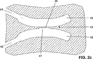
図2cに示したのは、本発明に係る薄肉連結部の別の実施の形態である。この図の実施の形態は、両側の凹形湾曲形状の線状スリット部領域42、43のうちの一方にだけ、薄肉連結領域41のくびれ部46を形成する陥凹部47を設けたものである。この構成によっても、薄肉連結部の断面積を減じて、しかも可撓ヒンジ部の揺動中心の位置を正確に定め得るという効果が得られる。
Shown in FIG. 2c is another embodiment of a thin connector according to the present invention. In the embodiment shown in this figure, a recessed
図2dに示したのは、本発明に係る薄肉連結部の更に別の実施の形態である。この図の実施の形態は、両側の凹形湾曲形状の線状スリット部領域52、53の各々において、第1陥凹部57、58の内側に更に第2陥凹部59、60を設けることによって、陥凹部を二重に設けたものである。この構成によれば、薄肉連結領域51の幅を更に狭めることができると共に、可撓ヒンジ部の揺動中心の位置も更に正確に定めることができる。尚、指摘するまでもなく明らかなことであるが、薄肉連結領域51の幅を更に狭めるのに、両側の凹形湾曲形状の線状スリット部領域52、53のうちの一方だけに第2の陥凹部を設けるようにしてもよく、更には、陥凹部を三重以上に重ねて、中央に近付くほど陥凹部が深くなるような構成とすることも考えられ、そのようなものも本発明に含まれる。
FIG. 2d shows still another embodiment of the thin connecting portion according to the present invention. In the embodiment shown in this figure, in each of the concave slit-shaped
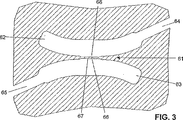
図3に示したのは、本発明に係る可撓ヒンジ部の薄肉連結部のまた別の構成例である。この図の構成例においては、2つの凹形湾曲形状の線状スリット部領域62、63に夫々接続している2本の境界画成用線状スリット部が、互いに逆方向から延在してきている。尚、この図に示した薄肉連結領域61のくびれ部66は、くびれ部の一例を示すために、図2bに示したくびれ部と同じ構成のものとしたが、これに限れらず、例えば図2cや図2dに示したものと同様のくびれ部としても構わないことは明らかである。
FIG. 3 shows another configuration example of the thin connecting portion of the flexible hinge portion according to the present invention. In the configuration example of this figure, two boundary-defining linear slit portions connected to the two concave curved
図4aに示したのは薄肉連結部の更に別の実施の形態である。この図の実施の形態は、線状スリット部領域82、83から成る肉抜部によって画成される薄肉連結領域81の形状を、両端部から中央へ向かって一定の収束角で幅が狭まる形状とし、それによって薄肉連結領域81の中央における厚さを狭めたものである。但し、図示した薄肉連結部の形状は、その収束角を甚だしく誇張して描いてある。本発明をこの図の実施の形態とする場合、その収束角は実際には非常に小さく、両側の線状スリット部領域82、83の間の間隔は、薄肉連結領域81の中央における間隔と、薄肉連結領域81の両端部に置ける間隔とで、僅か数μmしか違わない。薄肉連結領域81のくびれ部86をこの形状とすることにより、製作が容易である上に、可撓ヒンジ構造の揺動中心の位置も正確に定め得るという利点が得られる。また、薄肉連結領域81は、その厚さに対して長さが大きいため、既に説明したように、衝撃力が加わったときには一時的に弾性変形して、その衝撃力をかわすことができるという効果をもたらす。
Shown in FIG. 4a is yet another embodiment of a thin connector. In the embodiment shown in this figure, the shape of the thin-walled connecting
図4bに示したのは図4aに示した薄肉連結部の実施の形態の変更例である。この図の変更例では、薄肉連結領域91のくびれ部96の形状は、図2bに示した薄肉連結部のくびれ部の形状と同様のものであるが、但し、薄肉連結領域91を画成している線状スリット部領域92、93に設けた陥凹部97、98によって薄肉連結領域91の中央の幅を更に狭めてあり、その幅の狭め方を、例えば、薄肉連結領域91がそれら陥凹部97、98の部分において中央へ向かって一定の収束角で幅が狭まる形状となるようにしている。
FIG. 4b shows a modification of the embodiment of the thin connecting portion shown in FIG. 4a. In the modified example of this figure, the shape of the
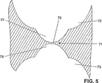
更に、可撓ヒンジ部を構成する薄肉連結部の形態に関して、その薄肉連結部を画成する肉抜部の凹形湾曲形状を略々一定の半径を有する形状とするようにしてもよい。このような薄肉連結部の形態が特に有利であるのは、荷重伝達機構を構成する構造ブロックの肉抜部を、例えばフライス加工などの切削加工によって形成する場合である。このような薄肉連結部の形態の具体的な構成例を示したのが図5であり、この図5も正しいスケールではなく、厚さに対して長さ方向の寸法を圧縮して描いてある。この図の構成においては、薄肉連結部71を画成している肉抜部が、略々一定の半径を有する円弧形状の切除部72、73に更にその半径より小さい第2半径を有する円弧形状の切除部77、78を形成して成る肉抜部となるように、薄肉連結領域71のくびれ部76の形状が定められている。
Furthermore, regarding the form of the thin connecting portion constituting the flexible hinge portion, the concave curved shape of the thinned portion defining the thin connecting portion may be a shape having a substantially constant radius. Such a thin-walled connection portion is particularly advantageous in the case where the lightening portion of the structural block constituting the load transmission mechanism is formed by cutting such as milling. FIG. 5 shows a specific configuration example of such a thin-walled connecting portion, and FIG. 5 is not a correct scale, and is drawn by compressing the dimension in the length direction with respect to the thickness. . In the configuration of this figure, the thinned portion defining the thin-walled connecting portion 71 has arcuate shapes having a second radius smaller than the
また、このような薄肉連結部の形態に更に変更を加えた形態として、その薄肉連結部を画成する肉抜部の形状を、略々一定の半径を有する円弧形状の切除部を更に追加して、内側に行くほど半径が小さくなる円弧形状の切除部を何重にも重ねた形状とするようにしてもよく、そのようなものも本発明に含まれる。 Further, as a form in which the form of the thin-walled connecting part is further changed, the shape of the thinned part defining the thin-walled connecting part is further added with an arc-shaped cut part having a substantially constant radius. Thus, the arc-shaped cut portions whose radius decreases toward the inner side may be formed into a shape in which multiple layers are stacked, and such a configuration is also included in the present invention.
また、薄肉連結部を画成するその薄肉連結部の両側の肉抜部のうちの一方にだけ、一定の半径を有する円弧形状の切除部を形成して、その薄肉連結部の片側にだけくびれ部を形成した形態とすることも考えられる。 Further, only one of the thinned portions on both sides of the thin-walled connecting portion that defines the thin-walled connecting portion is formed with an arc-shaped cutout portion having a certain radius, and is narrowed only on one side of the thin-walled connecting portion. It is also conceivable to form the part.
更に、上述したくびれ部と円弧形状の切除部とを組合せて、くびれ部を有する細長い薄肉連結部を画成しているその薄肉連結部の両側の肉抜部のうちの一方または両方に、一定の半径を有する円弧形状の切除部を設けるようにすることも考えられる。 Furthermore, a combination of the above-described constricted portion and the arc-shaped cut portion defines an elongated thin-walled connecting portion having a constricted portion, and is fixed to one or both of the thinned portions on both sides of the thin-walled connecting portion. It is also conceivable to provide an arc-shaped cut portion having a radius of.
また、これも指摘するまでもなく明らかなことであるが、先に図1に関連して説明したように、本発明に係る薄肉連結部を少なくとも1つ備えた可撓ヒンジ構造は、上述した平行四辺形リンク機構の変位平面に対して垂直な方向に、構造ブロックの全幅に亘って延在していることを必ずしも必要としない。本発明に係る荷重伝達機構における、連結要素の連結節点の幅寸法、及び、レバー部の支点の幅寸法を減じる方法としては、レバー部の揺動平面に対して平行な構造ブロックの一対の主面から陥没させて形成した切除部によって、それらの幅寸法を減じるようにしてもよく、また、構造ブロックの中心線上に形成した切除部によって、それらレバー部及び連結要素を分割するようにしてもよく、特に後者の場合には、それらレバー部ないし連結に付随する可撓ヒンジ部も共に分割するようにしてもよく、また、可撓ヒンジ部は分割せずに残すようにしてもよい。 Also, as will be clear without mentioning this, as described above with reference to FIG. 1, the flexible hinge structure having at least one thin-walled connecting portion according to the present invention has been described above. It does not necessarily need to extend over the entire width of the structural block in a direction perpendicular to the displacement plane of the parallelogram linkage. In the load transmission mechanism according to the present invention, as a method of reducing the width dimension of the connection node of the connection element and the width dimension of the fulcrum of the lever portion, a pair of main blocks of the structural block parallel to the swing plane of the lever portion is used. The width dimension may be reduced by a cut portion formed by being recessed from the surface, and the lever portion and the connecting element may be divided by a cut portion formed on the center line of the structural block. In particular, in the latter case, the lever part or the flexible hinge part associated with the connection may be divided together, or the flexible hinge part may be left without being divided.
1 構造ブロック
2 線状スリット部
2a 加工作業穴
3 平行四辺形リンク機構のリンク部
4 固定部
5 平行四辺形リンク機構の垂直方向に変位可能な側辺リンク部
6、6a、6b 連結要素の連結節点
7 荷重入力部
8 固定部の延出部
9 第1レバー部
10 第1(可撓)ヒンジ支点
11 平行四辺形リンク機構の可撓部
12 第3(可撓)ヒンジ支点
13 第1連結要素
14 第2連結要素
15 第2レバー部
16 第3連結要素
17 第3レバー部
19 孔
20 第2(可撓)ヒンジ支点
30 非貫通孔
21、31、41、51、61、71、81、91 薄肉連結領域
22、32、42、52、62、82、92 線状スリット部領域
23、33、43、53、63、83、93 線状スリット部領域
24、34、44、54、64、84、94 境界画成用線状スリット部
25、35、45、55、65、85、95 境界画成用線状スリット部
36、46、56、66、76、86、96 くびれ部
37、47、67、97 陥凹部
38、98 陥凹部
57、58 第1陥凹部
59、60 第2陥凹部
72、73 第1半径を有する円弧形状の切除部
77、78 第2半径を有する円弧形状の切除部
DESCRIPTION OF SYMBOLS 1 Structure block 2 Linear slit part 2a Processing work hole 3 Link part of a parallelogram link mechanism 4 Fixing part 5 Side link part 6, 6a, 6b which can be displaced to a perpendicular direction of a parallelogram link mechanism Connection of a connection element Node 7 Load input portion 8 Extension portion of fixed portion 9 First lever portion 10 First (flexible) hinge fulcrum 11 Flexible portion of parallelogram link mechanism 12 Third (flexible) hinge fulcrum 13 First connecting element 14 Second connecting element 15 Second lever part 16 Third connecting element 17 Third lever part 19 Hole 20 Second (flexible) hinge fulcrum 30 Non-through hole 21, 31, 41, 51, 61, 71, 81, 91 Thin connection area 22, 32, 42, 52, 62, 82, 92 Linear slit area 23, 33, 43, 53, 63, 83, 93 Linear slit area 24, 34, 44, 54, 64, 84 , 9 Boundary defining linear slit portions 25, 35, 45, 55, 65, 85, 95 Boundary defining linear slit portions 36, 46, 56, 66, 76, 86, 96 Constricted portions 37, 47, 67, 97 Depressions 38, 98 Depressions 57, 58 First depressions 59, 60 Second depressions 72, 73 Arc-shaped cuts having a first radius 77, 78 Arc-shaped cuts having a second radius
Claims (21)
前記連動リンク機構が、測定用トランスデューサへ荷重を伝達する少なくとも1つの変位伝達用レバー部と、該連動リンク機構に荷重を入力すると共に長手方向の荷重に対しては剛性を発揮する一方、曲げ荷重に対しては弾性変位する少なくとも一つの連結要素と、可撓ヒンジ部を構成すると共に前記少なくとも一つのレバー部を前記固定部乃至は連結されている別のレバー部に支持する可撓ヒンジ支点とを備え、前記連結要素が少なくとも一つの薄肉連結部を、また、前記可撓ヒンジ支点が一つの薄肉連結部を有する、可撓ヒンジ構造において、
前記薄肉連結部の少なくとも一つが、隣接する肉抜部により画成され且つ凹形湾曲形状の肉抜部により画成された少なくとも1つの薄肉連結領域を有し、該薄肉連結領域を画成する前記肉抜部の少なくとも1つが該薄肉連結領域にくびれ部を形成する形状であることを特徴とする可撓ヒンジ構造。 A flexible hinge structure that is a thin-walled connecting portion that is used in a load transmission mechanism including a fixed portion and an interlocking link mechanism and elastically connects solid portions to each other,
The interlocking link mechanism transmits at least one displacement transmitting lever portion for transmitting a load to the measuring transducer, and inputs a load to the interlocking link mechanism and exhibits rigidity with respect to a longitudinal load, while bending load. And at least one connecting element that elastically displaces, and a flexible hinge fulcrum that constitutes a flexible hinge part and supports the at least one lever part on the fixed part or another connected lever part. In the flexible hinge structure, wherein the connecting element has at least one thin-walled connecting portion, and the flexible hinge fulcrum has one thin-walled connecting portion,
At least one of the thin-walled connecting portions has at least one thin-walled connection region defined by an adjacent cut-out portion and defined by a concave curved shape of the thinned-out portion, and defines the thin-walled connection region. A flexible hinge structure characterized in that at least one of the thinned portions has a shape forming a constricted portion in the thin-walled connecting region.
前記連動リンク機構が、測定用トランスデューサへ荷重を伝達する少なくとも1つの変位伝達用レバー部と、該連動リンク機構に荷重を入力すると共に長手方向の荷重に対しては剛性を発揮する一方、曲げ荷重に対しては弾性変位する少なくとも一つの連結要素と、前記少なくとも一つのレバー部を前記固定部乃至は連結されている別のレバー部に支持する可撓ヒンジ支点とを備え、前記連結要素が少なくとも一つの薄肉連結部を、また、前記可撓ヒンジ支点が一つの薄肉連結部を有する、荷重伝達機構において、
前記薄肉連結部の少なくとも一つが、凹形湾曲形状の肉抜部により画成された少なくとも1つの薄肉連結領域を有し、該薄肉連結領域を画成する該肉抜部の少なくとも1つが該薄肉連結領域にくびれ部を形成する形状であることを特徴とする荷重伝達機構。
A load transmission mechanism for a load transmission device including a fixed portion and an interlocking link mechanism,
The interlocking link mechanism transmits at least one displacement transmitting lever portion for transmitting a load to the measuring transducer, and inputs a load to the interlocking link mechanism and exhibits rigidity with respect to a longitudinal load, while bending load. At least one connecting element that elastically displaces, and a flexible hinge fulcrum that supports the at least one lever part on the fixed part or another lever part connected thereto. In the load transmission mechanism in which one thin connection part and the flexible hinge fulcrum have one thin connection part,
At least one of the thin-walled connecting portions has at least one thin-walled connection region defined by a concavely curved thin-walled portion, and at least one of the thin-walled portions defining the thin-walled connection region is the thin-walled portion. A load transmission mechanism having a shape that forms a constricted portion in a connection region.
Applications Claiming Priority (2)
| Application Number | Priority Date | Filing Date | Title |
|---|---|---|---|
| DE10148762A DE10148762A1 (en) | 2001-10-02 | 2001-10-02 | Thin-point bending bearing for a force measuring device and device for transmitting force with such a device |
| PCT/IB2002/003973 WO2003029765A1 (en) | 2001-10-02 | 2002-09-26 | Narrow-sectioned elastic bearing for a force-measuring device and a force-transmission device which uses the same |
Publications (2)
| Publication Number | Publication Date |
|---|---|
| JP2006503261A JP2006503261A (en) | 2006-01-26 |
| JP3792697B2 true JP3792697B2 (en) | 2006-07-05 |
Family
ID=7701232
Family Applications (1)
| Application Number | Title | Priority Date | Filing Date |
|---|---|---|---|
| JP2003532931A Expired - Lifetime JP3792697B2 (en) | 2001-10-02 | 2002-09-26 | Flexible hinge structure for load measuring device and load transmission mechanism with flexible hinge structure |
Country Status (7)
| Country | Link |
|---|---|
| US (1) | US6886418B2 (en) |
| EP (1) | EP1436574B1 (en) |
| JP (1) | JP3792697B2 (en) |
| CN (1) | CN1329714C (en) |
| AT (1) | ATE299585T1 (en) |
| DE (2) | DE10148762A1 (en) |
| WO (1) | WO2003029765A1 (en) |
Families Citing this family (10)
| Publication number | Priority date | Publication date | Assignee | Title |
|---|---|---|---|---|
| US7653094B2 (en) * | 2005-03-24 | 2010-01-26 | Mitutoyo Corporation | External cavity laser with flexure tuning element |
| WO2008145426A1 (en) * | 2007-06-01 | 2008-12-04 | Mettler-Toledo Ag | Adjustable parallel guide especially for a gravimetric measuring instrument |
| DE202008008459U1 (en) * | 2008-06-24 | 2008-08-21 | Sartorius Ag | Weighing system with transmission lever |
| EP2434265B1 (en) * | 2010-09-22 | 2014-03-05 | Wipotec Wiege- und Positioniersysteme GmbH | Weighing device with thermal decoupling |
| EP2610596B2 (en) * | 2011-12-30 | 2022-03-30 | WIPOTEC GmbH | Bridging element for a scale |
| CN103323089B (en) * | 2012-03-23 | 2017-04-12 | 梅特勒-托利多公开股份有限公司 | Force transmission mechanism with calibrating balance weight capable of being connected and separated |
| DE102013108097B4 (en) * | 2013-07-29 | 2016-02-25 | Sartorius Lab Instruments Gmbh & Co. Kg | Method for manufacturing a force measuring body |
| WO2016188960A1 (en) | 2015-05-26 | 2016-12-01 | Mettler-Toledo Gmbh | Weigh module with parallel-guiding mechanism module |
| EP3502633A1 (en) * | 2017-12-21 | 2019-06-26 | Mettler-Toledo GmbH | Monolithic load cell |
| DE102019135732B4 (en) * | 2019-12-23 | 2021-09-23 | Neura Robotics GmbH | Device for measuring a change in length |
Family Cites Families (13)
| Publication number | Priority date | Publication date | Assignee | Title |
|---|---|---|---|---|
| DE8135182U1 (en) * | 1981-12-03 | 1982-04-15 | Sartorius GmbH, 3400 Göttingen | ELECTRONIC SCALE |
| US4799561A (en) * | 1987-05-09 | 1989-01-24 | Shimadzu Corporation | Electronic balance |
| DE3833221C2 (en) * | 1987-11-27 | 1997-01-30 | Sartorius Gmbh | System carrier for top-shell electronic precision scales |
| DE4022146A1 (en) * | 1989-07-19 | 1991-01-31 | Sartorius Gmbh | Weighing device with parallelogram linkage |
| DE4119734A1 (en) * | 1991-06-14 | 1992-12-17 | Mettler Toledo Ag | DEVICE FOR REDUCING FORCE IN A FORCE MEASURING DEVICE, IN PARTICULAR A SCALE |
| US5313023A (en) * | 1992-04-03 | 1994-05-17 | Weigh-Tronix, Inc. | Load cell |
| DE4305426A1 (en) * | 1993-02-22 | 1994-08-25 | Mettler Toledo Ag | Force measuring device, in particular scales |
| US5866854A (en) * | 1996-02-12 | 1999-02-02 | Mettler-Toledo Ag | Calibrating device for a balance |
| DE29708886U1 (en) * | 1996-07-19 | 1997-07-17 | Mettler Toledo Gmbh | Shock protection for a force measuring device |
| DE19729623B4 (en) * | 1997-07-10 | 2004-10-07 | Mettler-Toledo Gmbh | Arrangement for fastening a parallelogram guide in a force measuring device |
| US6414252B1 (en) * | 1998-11-16 | 2002-07-02 | Mettler-Toledo Gmbh | Calibration system for a weighing scale |
| DE19923208C1 (en) * | 1999-05-20 | 2000-10-12 | Sartorius Gmbh | Weighing device using electromagnetic force compensation has load sensor, transmission levers and associated coupling levers formed from single monolithic block |
| DE19943439A1 (en) * | 1999-09-11 | 2001-03-15 | Mettler Toledo Gmbh | Force reduction device in a force measuring device |
-
2001
- 2001-10-02 DE DE10148762A patent/DE10148762A1/en not_active Withdrawn
-
2002
- 2002-09-26 EP EP02777595A patent/EP1436574B1/en not_active Expired - Lifetime
- 2002-09-26 JP JP2003532931A patent/JP3792697B2/en not_active Expired - Lifetime
- 2002-09-26 AT AT02777595T patent/ATE299585T1/en not_active IP Right Cessation
- 2002-09-26 CN CNB028194993A patent/CN1329714C/en not_active Expired - Lifetime
- 2002-09-26 DE DE50203638T patent/DE50203638D1/en not_active Expired - Lifetime
- 2002-09-26 WO PCT/IB2002/003973 patent/WO2003029765A1/en active IP Right Grant
-
2004
- 2004-04-01 US US10/814,242 patent/US6886418B2/en not_active Expired - Lifetime
Also Published As
| Publication number | Publication date |
|---|---|
| EP1436574A1 (en) | 2004-07-14 |
| US20040182179A1 (en) | 2004-09-23 |
| CN1329714C (en) | 2007-08-01 |
| DE50203638D1 (en) | 2005-08-18 |
| EP1436574B1 (en) | 2005-07-13 |
| CN1564932A (en) | 2005-01-12 |
| ATE299585T1 (en) | 2005-07-15 |
| WO2003029765A1 (en) | 2003-04-10 |
| JP2006503261A (en) | 2006-01-26 |
| DE10148762A1 (en) | 2003-04-24 |
| US6886418B2 (en) | 2005-05-03 |
Similar Documents
| Publication | Publication Date | Title |
|---|---|---|
| JP3792697B2 (en) | Flexible hinge structure for load measuring device and load transmission mechanism with flexible hinge structure | |
| JP6700213B2 (en) | Transducer | |
| US7296364B2 (en) | Sensor module for a probe head of a tactile coordinated measuring machine | |
| US4585083A (en) | Mechanism for detecting load | |
| JP2678880B2 (en) | Integrated thin sensor | |
| US6414252B1 (en) | Calibration system for a weighing scale | |
| US6755087B2 (en) | Load cell having overload protection | |
| US6693245B2 (en) | Electronic balance which is easily assembled, maintained, downsized and improved with respect to weighing performance, and method for manufacturing the same | |
| JP6130895B2 (en) | Parallelogram linkage structure for weighers | |
| US20060076166A1 (en) | Force-transmitting mechanism for a balance | |
| US20090019948A1 (en) | Device for simultaneous measurement of forces | |
| JP6437592B2 (en) | Thin-wall joint | |
| JP6457018B2 (en) | Thin-wall joint | |
| JPH05172843A (en) | Semiconductor acceleration sensor | |
| CA1304238C (en) | Strain gage beam having integral overload protection | |
| JP5183977B2 (en) | Straining body for load cell, and load cell unit and weight measuring device using the same | |
| US7194819B2 (en) | Opposed type fulcrum member of lever detector | |
| JP2006047118A (en) | Load cell | |
| US4276772A (en) | Force transducer | |
| KR100778386B1 (en) | Load sensor with multiple measuring ranges | |
| KR102637073B1 (en) | Probe, method of manufacturing probe and scanning probe microscope system | |
| KR100965386B1 (en) | Micro force sensor | |
| JP5863491B2 (en) | Load cell | |
| US5742011A (en) | Load cell having a neutral plane spaced from a top surface thereof by a distance greater than from a bottom surface thereof | |
| JP2000214008A (en) | Integrated roverbal mechanism |
Legal Events
| Date | Code | Title | Description |
|---|---|---|---|
| TRDD | Decision of grant or rejection written | ||
| A01 | Written decision to grant a patent or to grant a registration (utility model) |
Free format text: JAPANESE INTERMEDIATE CODE: A01 Effective date: 20060323 |
|
| A61 | First payment of annual fees (during grant procedure) |
Free format text: JAPANESE INTERMEDIATE CODE: A61 Effective date: 20060405 |
|
| R150 | Certificate of patent or registration of utility model |
Ref document number: 3792697 Country of ref document: JP Free format text: JAPANESE INTERMEDIATE CODE: R150 Free format text: JAPANESE INTERMEDIATE CODE: R150 |
|
| S533 | Written request for registration of change of name |
Free format text: JAPANESE INTERMEDIATE CODE: R313533 |
|
| R350 | Written notification of registration of transfer |
Free format text: JAPANESE INTERMEDIATE CODE: R350 |
|
| FPAY | Renewal fee payment (event date is renewal date of database) |
Free format text: PAYMENT UNTIL: 20090414 Year of fee payment: 3 |
|
| FPAY | Renewal fee payment (event date is renewal date of database) |
Free format text: PAYMENT UNTIL: 20100414 Year of fee payment: 4 |
|
| R250 | Receipt of annual fees |
Free format text: JAPANESE INTERMEDIATE CODE: R250 |
|
| FPAY | Renewal fee payment (event date is renewal date of database) |
Free format text: PAYMENT UNTIL: 20100414 Year of fee payment: 4 |
|
| FPAY | Renewal fee payment (event date is renewal date of database) |
Free format text: PAYMENT UNTIL: 20110414 Year of fee payment: 5 |
|
| R250 | Receipt of annual fees |
Free format text: JAPANESE INTERMEDIATE CODE: R250 |
|
| S531 | Written request for registration of change of domicile |
Free format text: JAPANESE INTERMEDIATE CODE: R313531 |
|
| FPAY | Renewal fee payment (event date is renewal date of database) |
Free format text: PAYMENT UNTIL: 20120414 Year of fee payment: 6 |
|
| R250 | Receipt of annual fees |
Free format text: JAPANESE INTERMEDIATE CODE: R250 |
|
| FPAY | Renewal fee payment (event date is renewal date of database) |
Free format text: PAYMENT UNTIL: 20120414 Year of fee payment: 6 |
|
| R350 | Written notification of registration of transfer |
Free format text: JAPANESE INTERMEDIATE CODE: R350 |
|
| FPAY | Renewal fee payment (event date is renewal date of database) |
Free format text: PAYMENT UNTIL: 20130414 Year of fee payment: 7 |
|
| R250 | Receipt of annual fees |
Free format text: JAPANESE INTERMEDIATE CODE: R250 |
|
| FPAY | Renewal fee payment (event date is renewal date of database) |
Free format text: PAYMENT UNTIL: 20140414 Year of fee payment: 8 |
|
| R250 | Receipt of annual fees |
Free format text: JAPANESE INTERMEDIATE CODE: R250 |
|
| R250 | Receipt of annual fees |
Free format text: JAPANESE INTERMEDIATE CODE: R250 |
|
| R250 | Receipt of annual fees |
Free format text: JAPANESE INTERMEDIATE CODE: R250 |
|
| S533 | Written request for registration of change of name |
Free format text: JAPANESE INTERMEDIATE CODE: R313533 |
|
| R350 | Written notification of registration of transfer |
Free format text: JAPANESE INTERMEDIATE CODE: R350 |
|
| R250 | Receipt of annual fees |
Free format text: JAPANESE INTERMEDIATE CODE: R250 |
|
| R250 | Receipt of annual fees |
Free format text: JAPANESE INTERMEDIATE CODE: R250 |
|
| R250 | Receipt of annual fees |
Free format text: JAPANESE INTERMEDIATE CODE: R250 |
|
| R250 | Receipt of annual fees |
Free format text: JAPANESE INTERMEDIATE CODE: R250 |
|
| R250 | Receipt of annual fees |
Free format text: JAPANESE INTERMEDIATE CODE: R250 |
|
| R250 | Receipt of annual fees |
Free format text: JAPANESE INTERMEDIATE CODE: R250 |
|
| R250 | Receipt of annual fees |
Free format text: JAPANESE INTERMEDIATE CODE: R250 |
|
| EXPY | Cancellation because of completion of term |