JP3789757B2 - Object detection device - Google Patents
Object detection device Download PDFInfo
- Publication number
- JP3789757B2 JP3789757B2 JP2001013812A JP2001013812A JP3789757B2 JP 3789757 B2 JP3789757 B2 JP 3789757B2 JP 2001013812 A JP2001013812 A JP 2001013812A JP 2001013812 A JP2001013812 A JP 2001013812A JP 3789757 B2 JP3789757 B2 JP 3789757B2
- Authority
- JP
- Japan
- Prior art keywords
- light receiving
- beams
- light
- retroreflective material
- object detection
- Prior art date
- Legal status (The legal status is an assumption and is not a legal conclusion. Google has not performed a legal analysis and makes no representation as to the accuracy of the status listed.)
- Expired - Lifetime
Links
Images

Landscapes
- Geophysics And Detection Of Objects (AREA)
- Emergency Alarm Devices (AREA)
- Traffic Control Systems (AREA)
- Optical Radar Systems And Details Thereof (AREA)
Description
【0001】
【発明の属する技術分野】
本発明は、所定の物体(人も含む)が所定の監視領域内に存在するか否かを検出する物体検出装置及び方法に関するものである。
【0002】
【従来の技術】
種々の用途において、所定の物体が所定の監視領域内に存在するか否かを検出することが要請される。例えば、視覚障害者が監視領域内に進入したときに、警報を発したり現在位置を案内したりするために、視覚障害者が所定領域内に存在するか否かを検出することが要請される。
【0003】
従来から、このような要請に基づいて、例えば、特開平9−80165号公報に開示された物体検出装置が提供されている。この物体検出装置は、所定の監視領域の全体に一括して所定波長領域の光を照射する照射部と、前記所定波長領域の光による前記監視領域の像を撮像するCCDカメラと、CCDカメラから得られた画像信号に基づいて、検出すべき物体に予め設けられた再帰反射材であって前記所定波長領域の光を再帰反射する再帰反射材が、前記監視領域内に存在するか否かを判定する判定部と、を備えたものである。
【0004】
この物体検出装置によれば、再帰反射材は照射光の方向と略同一方向にのみ高輝度光を反射(再帰反射)する特性を有しているので、CCDカメラが撮像する再帰反射材の像の輝度は高輝度となる。このため、輝度差によって、再帰反射材の像を背景から容易に抽出することができる。したがって、高度な画像処理回路等の必要がなく、比較的簡単な構成で、精度良く物体を検出することができる。
【0005】
【発明が解決しようとする課題】
しかしながら、前記従来の物体検出装置では、高度な画像処理回路等は不要であるものの、CCDカメラ等の撮像手段が必要であるため、その分コストアップを免れなかった。
【0006】
そこで、CCDカメラ等に代えてフォトダイオード等の受光素子を用いることが考えられる。しかし、この場合、前記従来の物体検出装置のように監視領域の全体に一括して照射光を照射してしまうと、再帰反射材から反射される反射光(信号光)のみならず、監視領域における再帰反射材が存在していない大部分の領域からの反射光(地面、壁面その他の反射物からの反射光、すなわち、ノイズ光)も、同時に受光素子により受光されてしまうことになる。したがって、S/Nが大きく低下し、検出精度が大幅に低下してしまう。
【0007】
本発明は、このような事情に鑑みてなされたもので、撮像手段を用いずにコストダウンを図ることができ、しかも検出精度の高い物体検出装置を提供することを目的とする。
【0008】
【課題を解決するための手段】
前記課題を解決するため、本発明の第1の態様による物体検出装置は、所定の監視領域内の個々の複数の個別領域にそれぞれ複数本のビームを照射する照射手段と、検出すべき物体に予め設けられた再帰反射材であって前記ビームを再帰反射する再帰反射材からの、反射光を受光する受光手段と、前記受光手段からの信号に基づいて前記再帰反射材が前記監視領域内に存在するか否かを判定する判定手段と、を備え、前記照射手段は、前記複数本のビームのうちの2つ以上のビームを、互いに異なるタイミングで、あるいは、互いに異なる変調光として、あるいは、互いに異なるタイミングでかつ互いに異なる変調光として、照射するものである。
【0009】
この第1の態様によれば、撮像手段ではなく受光手段が用いられているので、前記従来の物体検出装置に比べて大幅にコストダウンを図ることができる。
【0010】
この第1の態様では、使用に際して、照射手段が照射する所定波長領域の光を再帰反射する再帰反射材を、検出すべき物体に予め設けておく。再帰反射材は、前述したように、照射光の方向と略同一方向にのみ高輝度光を反射(再帰反射)する特性を有している。
【0011】
したがって、照射手段により監視領域内の個々の複数の個別領域にそれぞれ複数本のビームが照射されるので、監視領域内に再帰反射材が存在すれば、受光手段は、再帰反射材からの高輝度の反射光を受光することになる。
【0012】
そして、前記第1の態様では、照射手段は、前記従来の物体検出装置と異なり、監視領域の全体に一括して同じ光を照射するのではなく、複数の個別領域にそれぞれ複数のビームを照射し、この複数本のビームのうちの2つ以上のビームを、互いに異なるタイミングで、あるいは、互いに異なる変調光として、あるいは、互いに異なるタイミングでかつ互いに異なる変調光として、照射する。したがって、前記第1の態様では、互いに同一タイミングでかつ互いに同一の変調光又は無変調光として照射される領域は、監視領域の一部に限定される。このため、前記第1の態様によれば、受光手段によって、再帰反射材から反射される反射光(信号光)と一緒に、当該信号光と識別不能に受光されるノイズ光(地面、壁面その他の反射物からの反射光)が低減される。その結果、S/Nが向上し、検出精度が高まる。
【0013】
このように、前記第1の態様によれば、撮像手段を用いずにコストダウンを図ることができ、しかも検出精度を高めることができる。
【0014】
本発明の第2の態様による物体検出装置は、前記第1の態様において、前記所定の監視領域は帯状の領域であり、前記照射手段は、前記複数本のビームがそれぞれ照射する前記個別領域が当該帯状の領域の延びる方向に沿って実質的に隙間をあけることなく一部重複してあるいは一部重複することなく並ぶように、前記複数本のビームを照射するものである。
【0015】
この第2の態様によれば、監視領域が帯状の領域であるので、この帯状の領域を通過しようとした物体を検出することができるとともに、照射手段が照射するビームの本数を減らすことができ、照射手段をより安価に構成することができる。しかも、複数のビームがそれぞれ照射する個別領域が当該帯状の領域の延びる方向に沿って実質的に隙間をあけることなく並ぶように、複数のビームが照射されるので、物体の検出漏れを防止することができる。
【0016】
もっとも、前記第1の態様では、監視領域は、帯状の領域に限定されるものではなく、必要に応じて、例えば、正方形等の領域としてもよい。
【0017】
前記第2の態様において、前記監視領域は、例えば、所定高さの水平面内において、直線状、V字状、L字状、円弧状又は円状に延びたものでもよい。これは、前記監視領域の具体例を挙げたものであるが、前記第2の態様では、監視領域の形状はこれらの例に限定されるものではなく、目的に応じて適宜定めることができる。
【0018】
本発明の第3の態様による物体検出装置は、前記第1又は第2の態様において、前記各ビームにより照射される前記個別領域の大きさは、前記再帰反射材をちょうどカバーする程度の大きさであるものである。
【0019】
前記個別領域の大きさをこの第3の態様のように定めると、S/Nをより向上させつつ、照射手段が照射するビームの本数をより減らすことができ、好ましい。
【0020】
本発明の第4の態様による物体検出装置は、前記第1乃至第3のいずれかの態様において、前記照射手段は、前記複数本のビームを上方から鉛直方向に対して斜めに照射するものである。
【0021】
この第4の態様のように、ビームを上方から鉛直方向に対して斜めに照射すると、例えば、信号機の箇所や駅のホームなどで視覚障害者に警報を発したり誘導の案内をしたりするために、検出しようとする物体が視覚障害者用の杖である場合、当該杖の先端が視覚障害者が進行する方向に斜め下方に差し出されることから、所定方向に進行する場合にのみ当該杖を検出することも可能となる。もっとも、前記第1乃至第3の態様では、前記複数本のビームを上方からほぼ鉛直方向に照射してもよい。
【0022】
前記第4の態様において、例えば、前記複数本のビームの主光線の鉛直方向に対する傾き角は、20゜以上40゜以下であってもよい。このように前記傾き角を設定すると、例えば、検出しようとする物体が視覚障害者用の杖である場合、当該杖に設けた再帰反射材が他の人の影に隠れ難くすることができるとともに、所定方向に進行する場合にのみ当該杖を検出する上で、より好ましい。前記傾き角は、25゜以上35゜以下であることが、より一層好ましい。
【0023】
本発明の第5の態様による物体検出装置は、前記第1乃至第4のいずれかの態様において、前記照射手段は、それぞれ前記複数本のビームの光源となる複数の発光素子であって複数のグループに分けられた複数の発光素子と、前記複数のグループにそれぞれ対応して設けられた複数のレンズ部と、を含み、前記各グループの発光素子から発したビームは当該グループに対応する同じレンズ部を通過した後に前記個別領域をそれぞれ照射するものである。
【0024】
この第5の態様によれば、レンズ部の数が少なくて済むので、構成が簡単となり一層コストダウンを図ることができ、しかも、前記第2の態様のような複数本のビームの配置を容易に実現することができる。
【0025】
本発明の第6の態様による物体検出装置は、前記第1乃至第5のいずれかの態様において、前記受光手段は、単一の受光素子と、該受光素子の前部に配置されたレンズ部とからなるものである。
【0026】
この第5の態様によれば、受光手段の構成が簡単となり、一層コストダウンを図ることができる。
【0027】
本発明の第7の態様による物体検出装置は、前記第1乃至第4のいずれかの態様において、前記受光手段は、受光素子と、該受光素子の前部に配置されたレンズ部とを含み、前記照射手段は、前記受光素子の両側にそれぞれ配置された複数の発光素子と、一方側に配置された発光素子の前部及び他方側に配置された発光素子の前部にそれぞれ配置された2つのレンズ部とを含み、前記受光素子の一方の側に配置された複数の発光素子から発する複数本のビームが照射する前記個別領域と、前記受光素子の他方の側に配置された複数の発光素子から発する複数本のビームが照射する前記個別領域とが、交互に並ぶものである。
【0028】
この第7の態様によれば、レンズ部の数がより一層少なくて済みより一層コストダウンを図ることができるとともに、前記第2の態様のような複数本のビームの配置を容易に実現することができる。
【0029】
本発明の第8の態様による物体検出装置は、前記第1乃至第7のいずれかの態様において、前記照射手段は、前記各ビームを各ビーム発生期間において複数回パルス状に照射し、前記判定手段は、前記各ビーム発生期間において、当該ビームのパルスに対応する前記受光手段からの信号のレベルが所定レベル以上であるパルスの数が、所定数以上であるか否かに基づいて、前記判定を行うものである。
【0030】
この第8の態様によれば、検出精度をより高めることができる。
【0031】
前記第1乃至第8のいずれかの態様において、前記複数本のビームは、例えば、近赤外波長領域の光であってもよい。このように近赤外波長領域の光を用いると、可視光等から識別することが可能となることから、検出精度をより高めることができる。
【0032】
また、前記第1乃至第8のいずれかの態様において、前記複数本のビームは、例えば、変調光であってもよい。このように変調光を用いると、太陽光等から識別することが可能となることから、屋外等においても検出精度をより高めることができる。
【0033】
本発明の第9の態様による物体検出装置は、前記第1乃至第8のいずれかの態様において、前記物体が視覚障害者用の杖であるものである。
【0034】
この第9の態様は、好ましい検出対象の例を挙げたものであるが、前記第1乃至第8の態様では、他の種々の物体の検出に用いてもよい。
【0035】
本発明の第10の態様による物体検出方法は、所定の監視領域内を個々の複数の個別領域に分け、前記複数の個別領域にそれぞれ複数本のビームを照射し、検出すべき物体に予め設けられた再帰反射材であって前記ビームを再帰反射する再帰反射材からの、反射光を受光手段で受光し、前記受光手段からの信号に基づいて前記再帰反射材が前記監視領域内に存在するか否かを判定する物体検出方法であって、前記複数本のビームのうちの2つ以上のビームを、互いに異なるタイミングで、あるいは、互いに異なる変調光として、あるいは、互いに異なるタイミングでかつ互いに異なる変調光として、照射するものである。
【0036】
この第10の態様によれば、前記第1の態様と同様の利点が得られる。
【0037】
【発明の実施の形態】
以下、本発明による物体検出装置及び方法について、図面を参照して説明する。
【0038】
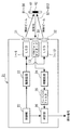
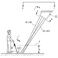
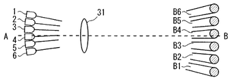
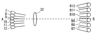
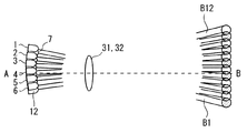
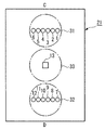
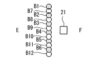
図1は、本発明の一実施の形態による物体検出装置21を示す概略構成図である。図2は、図1に示す物体検出装置21の配置例を模式的に示す概略縦断面図である。図3は、第1グループのLED1〜6及びこれらに対応する第1のレンズ31のみを示す図2中のA−B矢視図である。図4は、第2グループのLED7〜12及びこれらに対応する第2のレンズ32のみを示す図2中のA−B矢視図である。図5は、LED1〜12及びレンズ31,32を示す図2中のA−B矢視図である。図6は、図2中のC−D矢視図である。図7は、図2中のE−F矢視図である。
【0039】
本実施の形態による物体検出装置21は、図1乃至図7に示すように、それぞれ複数本のビームB1〜B12の光源となる複数の発光素子としての、第1グループのLED1〜6及び第2のグループのLED7〜12と、第1グループのLED1〜6に対応してそれらの前部に設けられた第1のレンズ31と、第2のグループのLED7〜12に対応してそれらの前部に設けられた第2のレンズ32と、検出すべき物体としての視覚障害者用の杖41に予め設けられた再帰反射材42で再帰反射された反射光を受光する受光素子としての、単一のPINフォトダイオード13と、PINフォトダイオード13の前部に配置された第3のレンズ33と、制御部22と、駆動回路23と、増幅回路24と、バンドパスフィルタ25と、判定部26と、を備えている。なお、本発明では、各グループのLEDの数や、発光素子の種類や、受光素子の種類などは、特に限定されるものではない。
【0040】
本実施の形態では、LED1〜12として、近赤外波長領域の光を発する赤外線LEDが用いられている。レンズ31〜33としては、凸レンズが用いられ、集光レンズとして作用するようになっている。装置の小型化を図るため、レンズ31〜33としてフレネルレンズを用いることが好ましい。例えば、レンズ31〜33が一体化されたレンズアレイを使用することもできる。
【0041】
図6に示すように、第1グループのLED1〜6は、PINフォトダイオード13の一方の側において、直線状に一列に配置されている。また、第2グループのLED7〜12は、PINフォトダイオード13の他方の側において、第1グループのLED1〜6の列と平行に直線状に一列に配置されている。個々のLED1〜12の向きや、レンズ31,32の焦点距離や、LED1〜6とレンズ31との位置関係や、LED7〜12とレンズ32との位置関係などが適宜調整・設定されることによって、第1グループのLED1〜6からそれぞれ発してレンズ31を通過したビームB1〜B6、及び、第2グループのLED7〜12からそれぞれ発してレンズ32を通過したビームB7〜B12は、図2乃至図5及び図7に示すように、照射されるようになっている。
【0042】
すなわち、ビームB1〜B12は、図2に示すように、上方から鉛直方向に対して斜めに照射される。ビームB1〜B12の鉛直方向に対する傾き角は、略々30゜となっている。なお、図2では、ビームB1〜B12を平行光束として示しているが、ビームB1〜B12は、拡散光束であってもよいことは言うまでもない。また、杖41の再帰反射材42の高さhと同じ高さの水平面P(図2参照)内における、ビームB1〜B12の各照射領域は、図3乃至図5中の右側の円形で示すとともに、図7中の円形で示すように、直線状に隙間をあけることなく一部重複して並んでいる。なお、図7では、ビームB1〜B12については、水平面P内での各照射領域のみを示している。水平面P内のビームB1〜B6の各照射領域は図3に示すように隙間をあけて並び、水平面P内のビームB7〜B12の各照射領域は図4に示すように隙間をあけて並ぶが、図5及び図7に示すように、これらの照射領域が交互に並ぶことによって、全体として直線状に隙間をあけることなく一部重複して並んでいる。もっとも、水平面P内のビームB1〜B12の各照射領域は、隙間をあけることなくかつ重複することなく並んでもよいし、若干隙間をあけて並んでもよい。
【0043】
本実施の形態では、前述したように、図6に示すように、第1グループのLED1〜6と第2グループのLED7〜12とがPINフォトダイオード13を挟んでその両側に配置されていることから、各LED1〜12とPINフォトダイオード13との間隔が狭まっている。このため、再帰反射材42は照射光の方向と略同一方向にのみ高輝度光を反射(再帰反射)する特性を有していることから、PINフォトダイオード13が、各LED1〜12から発して再帰反射材42で再帰反射した反射光を効率良く受光することができ、好ましい。図面には示していないが、レンズ31,32として光軸がPINフォトダイオード13の側に偏心した偏心レンズを用いると、前述したようなビームB1〜B12の配置を実現しつつ、LED1〜6の列とPINフォトダイオード13との間隔及びLED7〜12の列とPINフォトダイオード13との間隔を一層狭めることができ、より好ましい。
【0044】
本実施の形態では、水平面P内のビームB1〜B12の照射領域が全体として、監視領域を構成している。すなわち、本実施の形態では、監視領域は直線状の帯状領域となっており、水平面P内のビームB1〜B12の各照射領域は、監視領域内の個々の個別領域となっている。本実施の形態では、水平面P内のビームB1〜B12の各照射領域は、再帰反射材42をちょうどカバーする程度の大きさとなっている。もっとも、各照射領域の大きさはこのような大きさに限定されるものではない。
【0045】
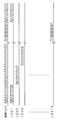
図1中の制御部22は、図8に示すように、例えば十数kHzの基準パルスを発生する。この基準パルスは、ビームB1〜B12の変調信号として用いられる。制御部22は、この基準パルスに基づいて、図8に示すようにLED1〜12をそれぞれ点灯制御するための点灯制御信号を生成し、これらの点灯制御信号を駆動回路23及び判定部26に供給する。本実施の形態では、各LED1〜12の点灯制御信号は、図8に示すように、基準パルスの8パルスずつを順次巡回的に振り分けたものとなっている。駆動回路23は、制御部22から供給された各LED1〜12用の点灯制御信号に従って、各LED1〜12を点灯駆動する。したがって、図8中の各点灯制御信号が「ハイ」の時に当該点灯制御信号に対応するLEDが点灯し、当該LEDに対応するビームが照射されることになる。このため、本実施の形態では、基準パルスの8パルス分の期間が各ビーム発生期間となっており、各ビームB1〜B12は、当該ビーム発生期間において8回パルス状に照射され、前記基準パルスで変調された変調光として照射される。また、ビームB1〜B12は、1つずつ順次照射され、互いに異なるタイミングで照射される。このように、本実施の形態では、全てのビームB1〜B12が互いに異なるタイミングで同じ変調光として照射されるが、本発明では、ビームB1〜B12のうちの2つ以上のビームが、互いに異なるタイミングで、あるいは、互いに異なる変調光として、あるいは、互いに異なるタイミングでかつ互いに異なる変調光として、照射すればよい。
【0046】
以上の説明からわかるように、本実施の形態では、LED1〜12、レンズ31,32、制御部22及び駆動回路23が、所定の監視領域内の個々の複数の個別領域にそれぞれ複数本のビームB1〜B12を、互いに異なるタイミングで照射する照射手段を、構成している。また、本実施の形態では、PINフォトダイオード13及びレンズ33が、検出すべき物体としての杖41に予め設けられた再帰反射材42であって前記ビームB1〜B12を再帰反射する再帰反射材42からの、反射光を受光する受光手段を、構成している。
【0047】
図1中の増幅回路24は、PINフォトダイオード13からの受光信号を増幅する。バンドパスフィルタ25は、増幅回路24により増幅された受光信号に対して、前記基準パルスの周波数の信号のみを濾波する。これにより、太陽光等のノイズ成分は除去される。バンドパスフィルタ25により濾波された受光信号は、判定部26に供給される。
【0048】
判定部26は、バンドパスフィルタ25により濾波された受光信号と、制御部22からの各LED1〜12用の点灯制御信号(すなわち、各LED1〜12の発光タイミング信号)とに基づいて、再帰反射材42が前記監視領域内に存在するか否かを判定し、存在する場合は感知信号(検出信号)を出力する。
【0049】
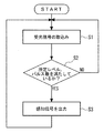
図9は、判定部26の動作の一例を示す概略フローチャートである。この例では、判定部26は、動作を開始すると、各LED1〜12用の点灯制御信号に同期して、図8中の1つのパルスについて、バンドパスフィルタ25により濾波された受光信号を取り込む(ステップS1)。次に、判定部26は、ステップS1で取り込まれた受光信号のレベルが所定レベル以上であるか否かを判定し、さらに現在までの各パルスに関するレベル判定結果に基づき、ステップS1で最新に取り込まれた受光信号に対応する図8中のパルスが属するビーム発生期間(本実施の形態では8パルス分の期間)において、所定レベル以上である旨のレベル判別結果の回数(受光信号が所定レベル以上であるパルスの数に相当)が所定回数(例えば、5回)以上であるか否かを判定する(ステップS2)。所定回数以上でなければ、ステップS1へ戻る。一方、所定回数以上であれば、再帰反射材42、すなわち、杖41が前記監視領域内に存在することを示す感知信号を出力する。
【0050】
判定部26が図9に示すような動作を行えば、検出精度が高まって好ましいが、本発明では、判定部26は、例えば、前記ステップS2において、ステップS1で取り込まれた受光信号のレベルが所定のレベル以上であるか否かを判定し、所定レベル以上であれば、直ちに感知信号を出力してもよい。また、判定部26は、感知信号を出力する際に、制御部26からの各LED1〜12の発光タイミング信号に基づいて、いずれのLED1〜12が発光しているときに感知されたかを示す信号(再帰反射材42の存在位置情報に相当)も、併せて出力してもよい。
【0051】
なお、前述した動作を行う制御部22及び判定部26は、例えば、PLD(Programmable Logic Device)やマイクロコンピュータ等を用いて構成することができる。
【0052】
本実施の形態によれば、撮像手段ではなく、PINフォトダイオード13及びレンズ33からなる受光手段が用いられているので、前記従来の物体検出装置に比べて大幅にコストダウンを図ることができる。
【0053】
本実施の形態によれば、監視領域内の個々の複数の個別領域にそれぞれ複数本のビームB1〜B12が照射されるので、図2に示すように、杖41を持った人が矢印X1方向に進行し、監視領域内に再帰反射材42が存在するようになれば、PINフォトダイオード13は、再帰反射材42からの高輝度の反射光を受光することになる。
【0054】
そして、本実施の形態では、前記従来の物体検出装置と異なり、監視領域の全体に一括して同じ光を照射するのではなく、複数の個別領域にそれぞれ複数のビームB1〜B12を、互いに異なるタイミングで照射する。したがって、本実施の形態は、互いに同一タイミングでかつ互いに同一の変調光として照射される領域は、監視領域のごく一部に限定される。このため、本実施の形態によれば、PINフォトダイオード13によって、再帰反射材42から反射される反射光(信号光)と一緒に、当該信号光と識別不能に受光されるノイズ光(地面、壁面その他の反射物からの反射光)が大幅に低減される。その結果、S/Nが向上し、検出精度が高まる。
【0055】
このように、本実施の形態によれば、撮像手段を用いずにコストダウンを図ることができ、しかも検出精度を高めることができる。
【0056】
また、本実施の形態によれば、前述したように監視領域が帯状領域であるので、この帯状領域を通過しようとした杖41を検出することができるとともに、照射するビームB1〜B12の本数を減らすことができ、照射手段をより安価に構成することができる。しかも、複数のビームB1〜B12がそれぞれ照射する個別領域が当該帯状の領域の延びる方向に沿って実質的に隙間をあけることなく並ぶように、複数のビームB1〜B12が照射されるので、杖41の検出漏れを防止することができる。
【0057】
さらに、本実施の形態によれば、前述したように、水平面P内のビームB1〜B12の各照射領域(各個別領域)は、再帰反射材42をちょうどカバーする程度の大きさとなっているので、S/Nをより向上させつつ、照射するビームB1〜B12の本数を減らすことができる。
【0058】
さらにまた、本実施の形態によれば、ビームB1〜B12を上方から鉛直方向に対して斜めに照射するので、当該杖の先端が視覚障害者が進行する方向に斜め下方に差し出されることから、所定方向X1に進行する場合にのみ当該杖41を検出することができる。したがって、進行方向に応じた案内等を行う際に、適している。
【0059】
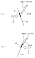
この点について、図10を参照して説明する。図10(a)は、図2に示す状態から杖41を持った人が矢印X1の方向に進行して、監視領域内に到達した状況を示している。この場合、再帰反射材42とビームB1〜B12との傾きの関係から、ビームB1〜B12のうち再帰反射材42を照射する光束の断面積が大きくなり、再帰反射材42で反射されてPINフォトダイオード13により受光される光量が大きくなるため、再帰反射材42が検出される。図10(b)は、杖41を持った人が逆方向(矢印X2)の方向に進行して、監視領域内に到達した状況を示している。この場合、再帰反射材42とビームB1〜B12との傾きの関係から、ビームB1〜B12のうち再帰反射材42を照射する光束の断面積が小さくなり、再帰反射材42で反射されてPINフォトダイオード13により受光される光量が小さくなるため、再帰反射材42が検出されない。
【0060】
特に、本実施の形態では、ビームB1〜B12の鉛直方向に対する傾き角が、略々30゜となっているので、所定方向X1に進行する場合にのみ当該杖41を検出する上で好ましいとともに、再帰反射材42が他の人の影に隠れ難くすることができる。この傾き角は、20゜以上40゜以下であってもよいが、25゜以上35゜以下であることがより一層好ましい。
【0061】
また、本実施の形態によれば、第1グループのLED1〜6に対して共通して1つのレンズ31が設けられ、第2グループのLED7〜12に対して共通して1つのレンズ32が設けられているので、レンズの数が少なくてすみ、よりコストダウンを図ることができる。
【0062】
さらに、本実施の形態によれば、単一のPINフォトダイオード13とその前部に配置されたレンズ33で受光手段が構成されているので、受光手段の構成が簡単となり、一層コストダウンを図ることができる。
【0063】
以上説明した実施の形態では、監視領域を直線状の帯状領域とした例であったが、本発明では、監視領域は、例えば、V字状、L字状、円弧状又は円状の帯状領域とすることができる。監視領域の形状は、用途に応じて自在に適宜定めることができる。
【0064】
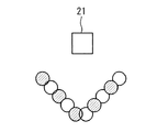
図11は監視領域を円状の帯状領域にした例、図12は監視領域をV字状の帯状領域にした例を示す。図11及び図12は、前述した図7に対応する、上方から見た概略平面図である。図11及び図12中の円状又はV字状の列をなす複数の円のうち、ハッチングを付した円は第1グループの各LEDから第1のレンズ31を通過して照射される各ビームの水平面P内の照射領域(個別領域)をそれぞれ示し、ハッチングを付していない円は第2グループの各LEDから第2のレンズ32を通過して照射される各ビームの水平面P内の照射領域(個別領域)をそれぞれ示す。
【0065】
図6を参照して説明すると、図11の場合には、例えば、前記物体検出装置21において、第1のグループの複数のLEDを円形に配列するとともに、第2のグループの複数のLEDを円形に配列し、これらのLEDの向きを適宜設定すればよい。図11の場合には、杖41を持った人が、いずれの方向から監視領域の内側に進行しても検出することができる。
【0066】
また、図12の場合には、例えば、前記物体検出装置21において、第1のグループの複数のLEDをV字状に配列するとともに、第2のグループの複数のLEDをV字状に配列し、これらのLEDの向きを適宜設定すればよい。
【0067】
以上、本発明の実施の形態とその変形例について説明したが、本発明はこれらの実施の形態又は変形例に限定されるものではない。
【0068】
【発明の効果】
以上説明したように、本発明によれば、撮像手段を用いずにコストダウンを図ることができ、しかも検出精度の高い物体検出装置を提供することができる。
【図面の簡単な説明】
【図1】本発明の一実施の形態による物体検出装置を示す概略構成図である。
【図2】図1に示す物体検出装置の配置例を模式的に示す概略縦断面図である。
【図3】第1グループのLED及びこれらに対応する第1のレンズのみを示す図2中のA−B矢視図である。
【図4】第2グループのLED及びこれらに対応する第2のレンズのみを示す図2中のA−B矢視図である。
【図5】第1及び第2のLED並びに第1及び第2のレンズを示す図2中のA−B矢視図である。
【図6】図2中のC−D矢視図である。
【図7】図2中のE−F矢視図である。
【図8】基準パルス及び点灯制御信号を示すタイミングチャートである。
【図9】判定部の動作の一例を示す概略フローチャートである。
【図10】進行方向の相違による検出の有無の様子を示す説明図である。
【図11】監視領域を円状の帯状領域にした例を示す上方から見た概略平面図である。
【図12】監視領域をV字状の帯状領域にした例を示す上方から見た概略平面図である。
【符号の説明】
1〜6 第1グループのLED
7〜12 第2グループのLED
13 PINフォトダイオード
21 物体検出装置
22 制御部
23 駆動回路
24 増幅回路
25 バンドパスフィルタ
26 判定部
31,32,33 レンズ
41 杖
42 再帰反射材[0001]
BACKGROUND OF THE INVENTION
The present invention relates to an object detection apparatus and method for detecting whether or not a predetermined object (including a person) is present in a predetermined monitoring area.
[0002]
[Prior art]
In various applications, it is required to detect whether a predetermined object exists within a predetermined monitoring area. For example, when a visually handicapped person enters the monitoring area, it is required to detect whether the visually handicapped person exists in a predetermined area in order to issue an alarm or guide the current position. .
[0003]
Conventionally, based on such a demand, for example, an object detection device disclosed in Japanese Patent Laid-Open No. 9-80165 has been provided. The object detection apparatus includes: an irradiation unit that collectively irradiates light of a predetermined wavelength region over the entire predetermined monitoring region; a CCD camera that captures an image of the monitoring region using light of the predetermined wavelength region; and a CCD camera. Based on the obtained image signal, it is determined whether or not a retroreflective material that is provided in advance on an object to be detected and retroreflects light in the predetermined wavelength region is present in the monitoring region. A determination unit for determining.
[0004]
According to this object detection apparatus, the retroreflective material has a characteristic of reflecting (retroreflecting) high-intensity light only in the substantially same direction as the direction of the irradiation light, so the image of the retroreflective material captured by the CCD camera The brightness of is high. For this reason, the image of the retroreflective material can be easily extracted from the background due to the luminance difference. Therefore, there is no need for an advanced image processing circuit or the like, and an object can be detected with high accuracy with a relatively simple configuration.
[0005]
[Problems to be solved by the invention]
However, although the conventional object detection apparatus does not require an advanced image processing circuit or the like, an imaging means such as a CCD camera is necessary, and thus the cost increase cannot be avoided.
[0006]
Therefore, it is conceivable to use a light receiving element such as a photodiode instead of a CCD camera or the like. However, in this case, if the entire monitoring area is irradiated with irradiation light as in the conventional object detection device, not only the reflected light (signal light) reflected from the retroreflective material but also the monitoring area Reflected light from most regions where no retroreflecting material exists (reflected light from the ground, wall surface, or other reflecting material, that is, noise light) is simultaneously received by the light receiving element. Therefore, the S / N is greatly reduced, and the detection accuracy is greatly reduced.
[0007]
The present invention has been made in view of such circumstances, and an object of the present invention is to provide an object detection apparatus that can reduce the cost without using an imaging unit and has high detection accuracy.
[0008]
[Means for Solving the Problems]
In order to solve the above problems, an object detection apparatus according to a first aspect of the present invention includes an irradiation unit that irradiates a plurality of individual regions within a predetermined monitoring region, and an object to be detected. A light receiving means for receiving reflected light from a retroreflective material provided in advance for retroreflecting the beam, and the retroreflective material within the monitoring area based on a signal from the light receiving means. Determination means for determining whether or not it exists, the irradiation means, two or more of the plurality of beams at different timings, as different modulation lights, or Irradiation is performed at different timings and as different modulated lights.
[0009]
According to the first aspect, since the light receiving means is used instead of the imaging means, the cost can be greatly reduced as compared with the conventional object detection apparatus.
[0010]
In this first aspect, in use, a retroreflecting material that retroreflects light in a predetermined wavelength region irradiated by the irradiation means is provided in advance on the object to be detected. As described above, the retroreflective material has a characteristic of reflecting (retroreflecting) high-intensity light only in substantially the same direction as the direction of irradiation light.
[0011]
Accordingly, since the irradiation unit irradiates a plurality of individual beams in each of the individual areas in the monitoring region, if the retroreflective material exists in the monitoring region, the light receiving unit is provided with high brightness from the retroreflective material. The reflected light is received.
[0012]
And in the said 1st aspect, unlike the said conventional object detection apparatus, an irradiation means does not irradiate the same light to the whole monitoring area | region collectively, but irradiates a some individual area | region with several beams, respectively. Then, two or more of the plurality of beams are irradiated at different timings, as different modulation lights, or as different modulation lights at different timings. Therefore, in the first aspect, a region irradiated with the same modulated light or non-modulated light at the same timing is limited to a part of the monitoring region. Therefore, according to the first aspect, the noise light (ground, wall surface, etc.) received indistinguishably from the signal light together with the reflected light (signal light) reflected from the retroreflecting material by the light receiving means. The reflected light from the reflector is reduced. As a result, S / N is improved and detection accuracy is increased.
[0013]
Thus, according to the first aspect, the cost can be reduced without using the imaging means, and the detection accuracy can be increased.
[0014]
The object detection apparatus according to a second aspect of the present invention is the object detection apparatus according to the first aspect, wherein the predetermined monitoring region is a band-shaped region, and the irradiation unit includes the individual regions irradiated with the plurality of beams, respectively. The plurality of beams are radiated so as to be partially overlapped or aligned without overlapping substantially along the extending direction of the band-shaped region.
[0015]
According to the second aspect, since the monitoring area is a band-shaped area, it is possible to detect an object that has attempted to pass through the band-shaped area and to reduce the number of beams irradiated by the irradiation unit. The irradiation means can be configured at a lower cost. In addition, since the plurality of beams are irradiated so that the individual regions irradiated with the plurality of beams are arranged substantially without any gap along the direction in which the band-shaped region extends, it is possible to prevent omission of detection of an object. be able to.
[0016]
But in the said 1st aspect, the monitoring area | region is not limited to a strip | belt-shaped area | region, For example, it is good also as areas, such as a square, as needed.
[0017]
In the second aspect, for example, the monitoring region may extend linearly, in a V shape, in an L shape, in an arc shape, or in a circular shape within a horizontal plane having a predetermined height. This is a specific example of the monitoring area, but in the second aspect, the shape of the monitoring area is not limited to these examples, and can be appropriately determined according to the purpose.
[0018]
In the object detection apparatus according to the third aspect of the present invention, in the first or second aspect, the size of the individual area irradiated by each beam is just large enough to cover the retroreflective material. It is what is.
[0019]
If the size of the individual area is determined as in the third mode, the number of beams irradiated by the irradiation unit can be further reduced while further improving the S / N, which is preferable.
[0020]
In the object detection device according to a fourth aspect of the present invention, in any one of the first to third aspects, the irradiation unit irradiates the plurality of beams obliquely with respect to the vertical direction from above. is there.
[0021]
When the beam is irradiated obliquely with respect to the vertical direction from above as in the fourth aspect, for example, to give a warning to a visually handicapped person or guide guidance at a traffic light or a station platform In addition, when the object to be detected is a cane for a visually impaired person, the tip of the cane is inserted obliquely downward in the direction in which the visually impaired person advances, so that the cane only when it advances in a predetermined direction. Can also be detected. But in the said 1st thru | or 3rd aspect, you may irradiate the said several beam to the substantially perpendicular direction from upper direction.
[0022]
In the fourth aspect, for example, an inclination angle of the principal rays of the plurality of beams with respect to a vertical direction may be 20 ° or more and 40 ° or less. When the tilt angle is set in this way, for example, when the object to be detected is a cane for a visually impaired person, the retroreflective material provided on the cane can be made difficult to hide in the shadow of another person. It is more preferable to detect the staff only when traveling in a predetermined direction. The tilt angle is more preferably 25 ° or more and 35 ° or less.
[0023]
The object detection apparatus according to a fifth aspect of the present invention is the object detection device according to any one of the first to fourth aspects, wherein the irradiation unit is a plurality of light emitting elements each serving as a light source of the plurality of beams. A plurality of light emitting elements divided into groups, and a plurality of lens portions provided corresponding to the plurality of groups, respectively, and beams emitted from the light emitting elements of each group are the same lens corresponding to the group Each of the individual areas is irradiated after passing through the section.
[0024]
According to the fifth aspect, since the number of lens portions can be reduced, the configuration can be simplified and the cost can be further reduced, and the arrangement of a plurality of beams as in the second aspect is easy. Can be realized.
[0025]
The object detection device according to a sixth aspect of the present invention is the object detection device according to any one of the first to fifth aspects, wherein the light receiving means includes a single light receiving element and a lens unit disposed in front of the light receiving element. It consists of
[0026]
According to the fifth aspect, the configuration of the light receiving means is simplified, and the cost can be further reduced.
[0027]
In the object detection device according to a seventh aspect of the present invention, in any one of the first to fourth aspects, the light receiving unit includes a light receiving element and a lens unit disposed in front of the light receiving element. The irradiating means is disposed at a plurality of light emitting elements respectively disposed on both sides of the light receiving element, a front part of the light emitting element disposed on one side, and a front part of the light emitting element disposed on the other side. A plurality of light emitting elements disposed on one side of the light receiving element and irradiated with a plurality of individual regions, and a plurality of light emitting elements disposed on the other side of the light receiving element. The individual regions irradiated with a plurality of beams emitted from the light emitting elements are alternately arranged.
[0028]
According to the seventh aspect, the number of lens portions can be further reduced, and the cost can be further reduced, and the arrangement of a plurality of beams as in the second aspect can be easily realized. Can do.
[0029]
The object detection apparatus according to an eighth aspect of the present invention is the object detection device according to any one of the first to seventh aspects, wherein the irradiation unit irradiates each beam in a pulse shape a plurality of times during each beam generation period. The means determines the determination based on whether or not the number of pulses in which the level of the signal from the light receiving means corresponding to the pulse of the beam is equal to or higher than a predetermined level in each beam generation period is equal to or higher than a predetermined number. Is to do.
[0030]
According to the eighth aspect, the detection accuracy can be further increased.
[0031]
In any one of the first to eighth aspects, the plurality of beams may be light in a near-infrared wavelength region, for example. When light in the near-infrared wavelength region is used in this way, it becomes possible to distinguish from visible light or the like, so that the detection accuracy can be further increased.
[0032]
In any one of the first to eighth aspects, the plurality of beams may be modulated light, for example. When modulated light is used in this way, it becomes possible to distinguish from sunlight or the like, so that the detection accuracy can be further increased even outdoors.
[0033]
An object detection apparatus according to a ninth aspect of the present invention is the object detection apparatus according to any one of the first to eighth aspects, wherein the object is a cane for a visually impaired person.
[0034]
The ninth aspect is an example of a preferable detection target, but the first to eighth aspects may be used for detecting other various objects.
[0035]
In the object detection method according to the tenth aspect of the present invention, a predetermined monitoring area is divided into a plurality of individual areas, each of the plurality of individual areas is irradiated with a plurality of beams, and the object to be detected is provided in advance. The reflected light from the retroreflective material that retroreflects the beam is received by the light receiving means, and the retroreflective material exists in the monitoring area based on the signal from the light receiving means. An object detection method for determining whether or not two or more of the plurality of beams are different from each other at different timings, as different modulation lights, or at different timings. Irradiated as modulated light.
[0036]
According to the tenth aspect, the same advantages as in the first aspect can be obtained.
[0037]
DETAILED DESCRIPTION OF THE INVENTION
Hereinafter, an object detection apparatus and method according to the present invention will be described with reference to the drawings.
[0038]
FIG. 1 is a schematic configuration diagram showing an
[0039]
As shown in FIGS. 1 to 7, the
[0040]
In the present embodiment, infrared LEDs that emit light in the near-infrared wavelength region are used as the
[0041]
As shown in FIG. 6, the first group of
[0042]
That is, as shown in FIG. 2, the beams B1 to B12 are irradiated obliquely with respect to the vertical direction from above. The inclination angle of the beams B1 to B12 with respect to the vertical direction is approximately 30 °. In FIG. 2, although the beams B1 to B12 are shown as parallel light beams, it goes without saying that the beams B1 to B12 may be diffused light beams. In addition, each irradiation region of the beams B1 to B12 in the horizontal plane P (see FIG. 2) having the same height as the height h of the
[0043]
In the present embodiment, as described above, as shown in FIG. 6, the first group of
[0044]
In the present embodiment, the irradiation areas of the beams B1 to B12 in the horizontal plane P constitute a monitoring area as a whole. That is, in the present embodiment, the monitoring area is a linear belt-like area, and each irradiation area of the beams B1 to B12 in the horizontal plane P is an individual area in the monitoring area. In the present embodiment, each irradiation region of the beams B <b> 1 to B <b> 12 in the horizontal plane P has a size that just covers the
[0045]
As shown in FIG. 8, the
[0046]
As can be seen from the above description, in the present embodiment, the
[0047]
The amplifying
[0048]
The
[0049]
FIG. 9 is a schematic flowchart illustrating an example of the operation of the
[0050]
If the
[0051]
In addition, the
[0052]
According to the present embodiment, since the light receiving means including the
[0053]
According to the present embodiment, since a plurality of beams B1 to B12 are irradiated to each of the plurality of individual regions in the monitoring region, as shown in FIG. If the
[0054]
And in this Embodiment, unlike the said conventional object detection apparatus, rather than irradiating the whole monitoring area | region with the same light collectively, several beams B1-B12 are mutually different to several separate area | regions, respectively. Irradiate at the timing. Therefore, in the present embodiment, the areas irradiated with the same modulated light at the same timing are limited to a very small part of the monitoring area. Therefore, according to the present embodiment, noise light (ground, ground) received by the
[0055]
As described above, according to the present embodiment, it is possible to reduce the cost without using the imaging means, and it is possible to increase the detection accuracy.
[0056]
Further, according to the present embodiment, since the monitoring area is a band-shaped area as described above, it is possible to detect the
[0057]
Furthermore, according to the present embodiment, as described above, each irradiation region (each individual region) of the beams B1 to B12 in the horizontal plane P is just large enough to cover the
[0058]
Furthermore, according to the present embodiment, since the beams B1 to B12 are irradiated obliquely with respect to the vertical direction from above, the tip of the cane is pushed obliquely downward in the direction in which the visually impaired person proceeds. The
[0059]
This point will be described with reference to FIG. FIG. 10A shows a situation in which the person holding the
[0060]
In particular, in the present embodiment, the inclination angle of the beams B1 to B12 with respect to the vertical direction is approximately 30 °, which is preferable for detecting the
[0061]
In addition, according to the present embodiment, one
[0062]
Furthermore, according to the present embodiment, since the light receiving means is constituted by the
[0063]
In the embodiment described above, the monitoring area is an example of a linear belt-shaped area. However, in the present invention, the monitoring area is, for example, a V-shaped, L-shaped, arc-shaped or circular belt-shaped area. It can be. The shape of the monitoring area can be appropriately determined according to the application.
[0064]
FIG. 11 shows an example in which the monitoring area is a circular belt-like area, and FIG. 12 shows an example in which the monitoring area is a V-shaped belt-like area. 11 and 12 are schematic plan views seen from above corresponding to FIG. 7 described above. Among the plurality of circles forming a circular or V-shaped row in FIGS. 11 and 12, the hatched circle is a beam irradiated from each LED of the first group through the
[0065]
Referring to FIG. 6, in the case of FIG. 11, for example, in the
[0066]
In the case of FIG. 12, for example, in the
[0067]
As mentioned above, although embodiment of this invention and its modification were demonstrated, this invention is not limited to these embodiment or modification.
[0068]
【The invention's effect】
As described above, according to the present invention, it is possible to reduce the cost without using the imaging means, and to provide an object detection device with high detection accuracy.
[Brief description of the drawings]
FIG. 1 is a schematic configuration diagram showing an object detection apparatus according to an embodiment of the present invention.
FIG. 2 is a schematic longitudinal sectional view schematically showing an arrangement example of the object detection device shown in FIG.
FIG. 3 is a view taken along the line AB in FIG. 2 showing only the first group of LEDs and the first lens corresponding to them.
FIG. 4 is a view taken along the line AB in FIG. 2 showing only the second group of LEDs and the second lens corresponding to them.
FIG. 5 is a view taken along the line AB in FIG. 2 showing the first and second LEDs and the first and second lenses.
6 is a view taken along arrow CD in FIG. 2. FIG.
7 is a view taken along the line EF in FIG. 2;
FIG. 8 is a timing chart showing a reference pulse and a lighting control signal.
FIG. 9 is a schematic flowchart illustrating an example of an operation of a determination unit.
FIG. 10 is an explanatory diagram showing the presence or absence of detection due to a difference in traveling direction.
FIG. 11 is a schematic plan view seen from above showing an example in which the monitoring area is a circular belt-like area.
FIG. 12 is a schematic plan view seen from above showing an example in which the monitoring region is a V-shaped strip region;
[Explanation of symbols]
1-6 LED of the first group
7-12 Second group of LEDs
13 PIN photodiode
21 Object detection device
22 Control unit
23 Drive circuit
24 Amplifier circuit
25 Bandpass filter
26 judgment part
31, 32, 33 lenses
41 Cane
42 Retroreflective material
Claims (11)
検出すべき物体に予め設けられた再帰反射材であって前記ビームを再帰反射する再帰反射材からの、反射光を受光する受光手段と、
前記受光手段からの信号に基づいて前記再帰反射材が前記監視領域内に存在するか否かを判定する判定手段と、
を備え、
前記照射手段は、前記複数本のビームのうちの2つ以上のビームを、互いに異なるタイミングで、あるいは、互いに異なる変調光として、あるいは、互いに異なるタイミングでかつ互いに異なる変調光として、照射し、
前記照射手段は、それぞれ前記複数本のビームの光源となる複数の発光素子であって複数のグループに分けられた複数の発光素子と、前記複数のグループにそれぞれ対応して設けられた複数のレンズ部と、を含み、前記各グループの発光素子から発したビームは当該グループに対応する同じレンズ部を通過した後に前記個別領域をそれぞれ照射することを特徴とする物体検出装置。Irradiating means for irradiating each of a plurality of individual regions within a predetermined monitoring region with a plurality of beams;
A light receiving means for receiving reflected light from a retroreflective material that is retroreflective material provided in advance on an object to be detected and retroreflects the beam;
Determination means for determining whether or not the retroreflective material is present in the monitoring region based on a signal from the light receiving means;
With
The irradiation means irradiates two or more of the plurality of beams at different timings, as different modulation lights, or as different modulation lights at different timings ,
The irradiation means includes a plurality of light emitting elements each serving as a light source of the plurality of beams, and a plurality of light emitting elements divided into a plurality of groups, and a plurality of lenses provided corresponding to the plurality of groups, respectively. A beam emitted from each group of light emitting elements irradiates the individual regions after passing through the same lens unit corresponding to the group .
検出すべき物体に予め設けられた再帰反射材であって前記ビームを再帰反射する再帰反射材からの、反射光を受光する受光手段と、Light receiving means for receiving reflected light from a retroreflective material that is retroreflective material provided in advance on the object to be detected and retroreflects the beam;
前記受光手段からの信号に基づいて前記再帰反射材が前記監視領域内に存在するか否かを判定する判定手段と、Determining means for determining whether or not the retroreflective material is present in the monitoring region based on a signal from the light receiving means;
を備え、With
前記照射手段は、前記複数本のビームのうちの2つ以上のビームを、互いに異なるタイミングで、あるいは、互いに異なる変調光として、あるいは、互いに異なるタイミングでかつ互いに異なる変調光として、照射し、The irradiation means irradiates two or more of the plurality of beams at different timings, as different modulation lights, or as different modulation lights at different timings,
前記受光手段は、受光素子と、該受光素子の前部に配置されたレンズ部とを含み、The light receiving means includes a light receiving element and a lens unit disposed in front of the light receiving element,
前記照射手段は、前記受光素子の両側にそれぞれ配置された複数の発光素子と、一方側に配置された複数の発光素子の前部及び他方側に配置された複数の発光素子の前部にそれぞれ配置された2つのレンズ部とを含み、The irradiation means includes a plurality of light emitting elements disposed on both sides of the light receiving element, a front portion of the plurality of light emitting elements disposed on one side, and a front portion of the plurality of light emitting elements disposed on the other side, respectively. Two lens parts arranged,
前記受光素子の一方の側に配置された複数の発光素子から発する複数本のビームが照射する前記個別領域と、前記受光素子の他方の側に配置された複数の発光素子から発する複数本のビームが照射する前記個別領域とが、交互に並ぶことを特徴とする物体検出装置。The individual region irradiated with a plurality of beams emitted from a plurality of light emitting elements arranged on one side of the light receiving element, and a plurality of beams emitted from a plurality of light emitting elements arranged on the other side of the light receiving element The object detection apparatus, wherein the individual areas irradiated by the are arranged alternately.
検出すべき物体に予め設けられた再帰反射材であって前記ビームを再帰反射する再帰反射材からの、反射光を受光する受光手段と、Light receiving means for receiving reflected light from a retroreflective material that is retroreflective material provided in advance on the object to be detected and retroreflects the beam;
前記受光手段からの信号に基づいて前記再帰反射材が前記監視領域内に存在するか否かを判定する判定手段と、Determining means for determining whether or not the retroreflective material is present in the monitoring region based on a signal from the light receiving means;
を備え、With
前記照射手段は、前記複数本のビームのうちの2つ以上のビームを、互いに異なるタイミングで、あるいは、互いに異なる変調光として、あるいは、互いに異なるタイミングでかつ互いに異なる変調光として、照射し、The irradiation means irradiates two or more of the plurality of beams at different timings, as different modulation lights, or as different modulation lights at different timings,
前記照射手段は、前記各ビームを各ビーム発生期間において複数回パルス状に照射し、前記判定手段は、前記各ビーム発生期間において、当該ビームのパルスに対応する前記受光手段からの信号のレベルが所定レベル以上であるパルスの数が、所定数以上であるか否かに基づいて、前記判定を行うことを特徴とする物体検出装置。The irradiating means irradiates each beam in a plurality of times in each beam generation period, and the determination means has a signal level from the light receiving means corresponding to the pulse of the beam in each beam generation period. An object detection apparatus that performs the determination based on whether or not the number of pulses that are equal to or higher than a predetermined level is equal to or higher than a predetermined number.
検出すべき物体に予め設けられた再帰反射材であって前記ビームを再帰反射する再帰反射材からの、反射光を受光する受光手段と、Light receiving means for receiving reflected light from a retroreflective material that is retroreflective material provided in advance on the object to be detected and retroreflects the beam;
前記受光手段からの信号に基づいて前記再帰反射材が前記監視領域内に存在するか否かを判定する判定手段と、Determining means for determining whether or not the retroreflective material is present in the monitoring region based on a signal from the light receiving means;
を備え、With
前記物体が視覚障害者用の杖であり、The object is a cane for the visually impaired,
前記照射手段は、前記複数本のビームのうちの2つ以上のビームを、互いに異なるタイミングで、あるいは、互いに異なる変調光として、あるいは、互いに異なるタイミングでかつ互いに異なる変調光として、照射し、The irradiation means irradiates two or more of the plurality of beams at different timings, as different modulation lights, or as different modulation lights at different timings,
前記照射手段は、前記再帰反射材で反射されて前記受光手段により受光される光量が前記再帰反射材の向きに応じて変わるように、前記複数本のビームを上方から鉛直方向に対して斜めに照射し、The irradiating means divides the plurality of beams obliquely from above in the vertical direction so that the amount of light reflected by the retroreflecting material and received by the light receiving means changes according to the direction of the retroreflecting material. Irradiated,
前記判定手段は、前記再帰反射材が所定方向を向いた状態で前記監視領域内に存在するか否かを判定することを特徴とする物体検出装置。The determination unit determines whether or not the retroreflective material is present in the monitoring region in a state of facing a predetermined direction.
Priority Applications (1)
| Application Number | Priority Date | Filing Date | Title |
|---|---|---|---|
| JP2001013812A JP3789757B2 (en) | 2001-01-22 | 2001-01-22 | Object detection device |
Applications Claiming Priority (1)
| Application Number | Priority Date | Filing Date | Title |
|---|---|---|---|
| JP2001013812A JP3789757B2 (en) | 2001-01-22 | 2001-01-22 | Object detection device |
Publications (2)
| Publication Number | Publication Date |
|---|---|
| JP2002214361A JP2002214361A (en) | 2002-07-31 |
| JP3789757B2 true JP3789757B2 (en) | 2006-06-28 |
Family
ID=18880603
Family Applications (1)
| Application Number | Title | Priority Date | Filing Date |
|---|---|---|---|
| JP2001013812A Expired - Lifetime JP3789757B2 (en) | 2001-01-22 | 2001-01-22 | Object detection device |
Country Status (1)
| Country | Link |
|---|---|
| JP (1) | JP3789757B2 (en) |
Families Citing this family (21)
| Publication number | Priority date | Publication date | Assignee | Title |
|---|---|---|---|---|
| JP4592200B2 (en) * | 2001-03-02 | 2010-12-01 | 小糸工業株式会社 | Crossing support detection apparatus and crossing support system using the same |
| JP5550134B2 (en) * | 2009-12-04 | 2014-07-16 | 大和製罐株式会社 | Inspection method for defective sealing of containers using infrared rays |
| JP5469446B2 (en) * | 2009-12-22 | 2014-04-16 | パナソニック株式会社 | Object detection device |
| JP2011141142A (en) * | 2010-01-05 | 2011-07-21 | Sharp Corp | Range finder and electronic equipment |
| WO2014097941A1 (en) * | 2012-12-20 | 2014-06-26 | 株式会社アルファ | Photosensor unit |
| US9733122B2 (en) | 2012-12-20 | 2017-08-15 | Alpha Corporation | Photosensor lens including a purality of convex lens surfaces |
| JP6258609B2 (en) * | 2013-06-17 | 2018-01-10 | 株式会社ヒューマンアセンブラ | Muscle strength measuring device and muscle strength measuring method |
| DE102014101195A1 (en) * | 2014-01-31 | 2015-08-06 | Huf Hülsbeck & Fürst Gmbh & Co. Kg | Assembly module for a motor vehicle |
| US10761195B2 (en) | 2016-04-22 | 2020-09-01 | OPSYS Tech Ltd. | Multi-wavelength LIDAR system |
| KR101701419B1 (en) * | 2016-08-17 | 2017-02-02 | 주식회사 오토닉스 | Reflective type image detecting sensor |
| KR102326493B1 (en) | 2017-03-13 | 2021-11-17 | 옵시스 테크 엘티디 | Eye-Safe Scanning LIDAR System |
| WO2019022941A1 (en) | 2017-07-28 | 2019-01-31 | OPSYS Tech Ltd. | Vcsel array lidar transmitter with small angular divergence |
| KR102589319B1 (en) | 2017-11-15 | 2023-10-16 | 옵시스 테크 엘티디 | Noise adaptive solid-state lidar system |
| WO2019195054A1 (en) | 2018-04-01 | 2019-10-10 | OPSYS Tech Ltd. | Noise adaptive solid-state lidar system |
| JP2021532368A (en) | 2018-08-03 | 2021-11-25 | オプシス テック リミテッド | Distributed modular solid-state lidar system |
| EP3953727A4 (en) | 2019-04-09 | 2023-01-04 | Opsys Tech Ltd. | SOLID STATE LIDAR TRANSMITTER WITH LASER CONTROL |
| US11846728B2 (en) | 2019-05-30 | 2023-12-19 | OPSYS Tech Ltd. | Eye-safe long-range LIDAR system using actuator |
| CN114096882B (en) | 2019-06-25 | 2025-12-23 | 欧普赛斯技术有限公司 | Adaptive multi-pulse LIDAR system |
| US11644571B2 (en) | 2019-07-01 | 2023-05-09 | Samsung Electronics Co., Ltd. | Electronic apparatus and control method thereof |
| US12222445B2 (en) | 2019-07-31 | 2025-02-11 | OPSYS Tech Ltd. | High-resolution solid-state LIDAR transmitter |
| JP7484380B2 (en) * | 2019-11-25 | 2024-05-16 | 大日本印刷株式会社 | Detection device |
-
2001
- 2001-01-22 JP JP2001013812A patent/JP3789757B2/en not_active Expired - Lifetime
Also Published As
| Publication number | Publication date |
|---|---|
| JP2002214361A (en) | 2002-07-31 |
Similar Documents
| Publication | Publication Date | Title |
|---|---|---|
| JP3789757B2 (en) | Object detection device | |
| EP3850916B1 (en) | Luminaire system for determining weather related information | |
| JP6468482B2 (en) | IMAGING DEVICE, OBJECT DETECTION DEVICE, AND MOBILE DEVICE CONTROL SYSTEM | |
| WO2017009848A1 (en) | Gated structured imaging | |
| KR20150065473A (en) | Camera for depth image measure and method of measuring depth image using the same | |
| US6856935B1 (en) | Camera tracking system for a virtual television or video studio | |
| PT2306428E (en) | Device and method for determining the direction, speed and/or distance of vehicles | |
| ES2401785T3 (en) | Structured Light Generator | |
| CN102483798A (en) | Illumination Optical System for Camera Devices | |
| ES2734901T3 (en) | Apparatus and methods for inspecting a composite structure to detect defects | |
| US20120218415A1 (en) | Imaging intrusion detection system and method using dot lighting | |
| JPH09325262A (en) | Range finder | |
| JP2014157124A (en) | Person detection device | |
| CN1276539A (en) | Multi-point ranging device | |
| JP5605565B2 (en) | Object identification device and object identification method | |
| KR100310518B1 (en) | Device and method for two-dimensionally determining pendulum swing and/or rotation of burden at a crane | |
| JP2003281686A (en) | Distance image sensor and vehicle type distinguishing device | |
| ES2804547T3 (en) | System for the optical detection of objects | |
| JPH10268067A (en) | Snow depth measurement device | |
| JP4210770B2 (en) | Sensor camera aiming mechanism | |
| JP4592200B2 (en) | Crossing support detection apparatus and crossing support system using the same | |
| US9052233B2 (en) | Sensor for venous networks of a part of a living body | |
| JP5240085B2 (en) | Object identification device | |
| JP3286168B2 (en) | Object detection apparatus and method | |
| JP4885373B2 (en) | Method and apparatus for light facing a light receiving part in a headlight tester |
Legal Events
| Date | Code | Title | Description |
|---|---|---|---|
| A977 | Report on retrieval |
Free format text: JAPANESE INTERMEDIATE CODE: A971007 Effective date: 20040402 |
|
| A131 | Notification of reasons for refusal |
Free format text: JAPANESE INTERMEDIATE CODE: A131 Effective date: 20050315 |
|
| A521 | Written amendment |
Free format text: JAPANESE INTERMEDIATE CODE: A523 Effective date: 20050428 |
|
| TRDD | Decision of grant or rejection written | ||
| A01 | Written decision to grant a patent or to grant a registration (utility model) |
Free format text: JAPANESE INTERMEDIATE CODE: A01 Effective date: 20060328 |
|
| A61 | First payment of annual fees (during grant procedure) |
Free format text: JAPANESE INTERMEDIATE CODE: A61 Effective date: 20060329 |
|
| R150 | Certificate of patent or registration of utility model |
Free format text: JAPANESE INTERMEDIATE CODE: R150 |
|
| FPAY | Renewal fee payment (event date is renewal date of database) |
Free format text: PAYMENT UNTIL: 20090407 Year of fee payment: 3 |
|
| FPAY | Renewal fee payment (event date is renewal date of database) |
Free format text: PAYMENT UNTIL: 20100407 Year of fee payment: 4 |
|
| FPAY | Renewal fee payment (event date is renewal date of database) |
Free format text: PAYMENT UNTIL: 20110407 Year of fee payment: 5 |
|
| FPAY | Renewal fee payment (event date is renewal date of database) |
Free format text: PAYMENT UNTIL: 20120407 Year of fee payment: 6 |
|
| S533 | Written request for registration of change of name |
Free format text: JAPANESE INTERMEDIATE CODE: R313533 |
|
| FPAY | Renewal fee payment (event date is renewal date of database) |
Free format text: PAYMENT UNTIL: 20120407 Year of fee payment: 6 |
|
| R350 | Written notification of registration of transfer |
Free format text: JAPANESE INTERMEDIATE CODE: R350 |
|
| FPAY | Renewal fee payment (event date is renewal date of database) |
Free format text: PAYMENT UNTIL: 20130407 Year of fee payment: 7 |
|
| FPAY | Renewal fee payment (event date is renewal date of database) |
Free format text: PAYMENT UNTIL: 20140407 Year of fee payment: 8 |
|
| R250 | Receipt of annual fees |
Free format text: JAPANESE INTERMEDIATE CODE: R250 |