JP3788127B2 - Image forming apparatus - Google Patents
Image forming apparatus Download PDFInfo
- Publication number
- JP3788127B2 JP3788127B2 JP24427799A JP24427799A JP3788127B2 JP 3788127 B2 JP3788127 B2 JP 3788127B2 JP 24427799 A JP24427799 A JP 24427799A JP 24427799 A JP24427799 A JP 24427799A JP 3788127 B2 JP3788127 B2 JP 3788127B2
- Authority
- JP
- Japan
- Prior art keywords
- image
- recording
- recording paper
- size
- paper
- Prior art date
- Legal status (The legal status is an assumption and is not a legal conclusion. Google has not performed a legal analysis and makes no representation as to the accuracy of the status listed.)
- Expired - Fee Related
Links
Images


Description
【0001】
【発明の属する技術分野】
本発明は画像形成装置に関し、特に、デジタル画像データに基づきたとえば銀塩の感光紙に対して露光を行って画像を形成する画像形成装置に関する。
【0002】
【従来の技術】
従来からデジタル画像データに基づいて画像形成を行うデジタルプリンタ等の画像形成装置がよく知られている。この画像形成装置は、いわゆるプリンタとしてだけではなく、たとえば複写機やファクシミリ装置等の画像形成部としても用いられる。
【0003】
このような画像形成装置には、レーザー方式、電子写真方式、サーマル方式またはインクジェット方式等の様々な方式が用いられ、これらの方式を採用した画像形成装置が広く市場に供給されている。
【0004】
この中で、画像形成にインクや微粒子のトナー等を用いる方式の画像形成装置においては、鮮鋭性や階調性といった画質の向上については長足の進歩が認められるものの、形成される画像の微細化の程度や発色性等に課題があるのが現状であり、ハロゲン化銀(銀塩)写真感光材料を用いた写真画像と比べると、画質に隔たりがある。
【0005】
近年、銀塩の感光紙を記録紙として用いるとともに、記録紙に対して露光する際の光源としてたとえばB(青)、G(緑)、R(赤)の三原色を発光するLED(発光ダイオード)を用いたLEDプリンタが提案されている。このLEDプリンタによれば、銀塩写真画像により近い画質の画像を得ることができるので、最近脚光を浴びてきている。
【0006】
また、このLEDプリンタにおいて露光用光源として用いるLEDは、その発光波長を従来のアナログ露光用の銀塩感光紙の感度域に近づけられるため、このLEDプリンタにおいては、現在広く流通している銀塩感光紙をそのまま使用することができるという有利さがある。
【0007】
【発明が解決しようとする課題】
しかしながら、上述のLEDプリンタにおいて露光に用いるLEDも、前述の利点はあるものの、実際に使用する場合には、感光紙に適正な露光を与えるため発光強度や発光分布等の条件や精度が適正である必要があり、その調整は複雑なものとなっている。
【0008】
すなわち、LEDプリンタにおいては、一般に、B、G、Rの各色ごとに複数のLEDを設けてユニットを構成し、このユニットによってLED露光ヘッドを構成している。このため、このLED露光ヘッドを用いた場合、各ユニット内においてもLED個々の製造上の特性ばらつきに起因する輝度ばらつきや、複数のLEDの配列における配列誤差等の影響を受けて、発光強度や発光分布等が変動してしまう。
【0009】
さらにB、G、Rの各ユニット間においてもLED特性自体の相違等によってばらつきが生じるため、プリント仕上げの品質向上のためには、ユニットの各種検査や調整が欠かせないものであった。
【0010】
また、露光のための発光が適正に行えたとしても、感光紙の種類の相違や製造ロットの相違等による感光特性等のばらつき、あるいは、露光された感光紙を現像するときの現像液の劣化状態や現像液の温度と現像時間や乾燥時間等による影響、さらには環境の温度や湿度等の影響が複雑に絡んでプリントの品質に大きな影響を与える。
【0011】
このため、上述の様々な影響を考慮した装置の制御に努める必要があるが、すべての組み合わせを完全に自動的に行えるものではなく、プリント実行前に所定の条件を設定した上でテストプリントを実行し、その結果を見てユーザーが設定条件の変更を繰り返しているのが現状であり、より高品質なプリント結果を得ようとすると、プリント開始前にテストプリント結果に応じて煩雑な条件設定を行う必要があり、ユーザーがこの条件設定を行うには、画像形成装置の操作方法に関する知識に限らず、感光紙の特性や現像条件等に関する高い知識が要求されていた。
【0012】
さらに、ユーザーが満足する、より高品質の画像を提供するためには、原画像を極めて忠実に再現するばかりではなく、場合によってはユーザー要望による変更、たとえば、画像の部分的な発色や濃度、階調の変更、あるいは原画像の拡大や縮小、複数の画像によるレイアウトの変更等を行った場合においても、プリント全体の画像の品質を高品質にできるようにしなければならない。しかし、このような場合、前述の各種ばらつきや各種条件の相違によるプリント仕上がりを考慮したプリント条件の設定を行おうとしても、テストプリント時に使用するチャートが、発色や濃度、階調等の基本的な設定に対するチャートの場合には、テストプリント結果を見ても実際の変更部分の仕上がり状態に対応したチャートではないために判断ができず、結果として設定した条件で、プリントしたい画像を一度プリントし、その結果を見て判断せざるを得ず、満足な結果が得られるまでには、繰り返し無駄なプリントを行っていた。
【0013】
このため、画像形成装置自体を各種画像処理技術に対応した制御が実現できる高精度の機構にしたり、メモリ構成や処理手順等を改善して画像形成装置自体の操作等を容易にするとともに、テストプリント時に使用する各種チャート等においても、高い知識を必要とせず、各種条件の設定や確認が容易にできるよう、実行する画像処理に対応した見やすいチャートに、また、テストプリントの出力も設定条件と仕上がりとが一目でわかるように改善する等の総合的な改善が望まれている。
【0014】
本発明は上記の点にかんがみてなされたもので、上述の課題を総合的に改善した画像形成装置を提供することを目的とする。
【0015】
【課題を解決するための手段】
本発明は、上記の目的を達成するために、外部のサイズ指示手段によって指示されたサイズに長尺の記録紙を切断する記録紙切断手段と、該記録紙切断手段によって切断された記録紙に対して画像記録を行う画像記録手段と、前記記録紙切断手段によって切断された記録紙を前記画像記録手段によって画像記録がされる位置まで搬送する給紙手段と、前記画像記録手段によって画像記録がされる位置にある記録紙を外部に排出する排紙手段とを有する画像形成装置において、前記記録紙切断手段による記録紙の切断が行われた後であって前記画像記録手段による画像記録が行われる前に、画像記録中止指示手段によって画像記録中止が指示された場合には、前記切断済み記録紙を内部に一時保持し、次回の画像記録時に前記サイズ指示手段から指示されたサイズと前記一時保持している切断済み記録紙のサイズとの大小関係に基づいて、前記一時保持している切断済み記録紙に対して前記次回の画像記録時の画像を記録するか、それとも、前記一時保持している切断済み記録紙を排出し新たに切断する記録紙に対して前記次回の画像記録時の画像を記録するかを決定する制御手段を備えたことを特徴とする。
【0038】
また、本発明は、請求項1に記載の画像形成装置において、前記次回の画像記録時に前記サイズ指示手段から指示されたサイズと前記一時保持している切断済み記録紙のサイズとが一致した場合にのみ、前記一時保持している切断済み記録紙に対して前記次回の画像記録時の画像を記録することを特徴とする。
【0039】
また、本発明は、請求項1に記載の画像形成装置において、前記次回の画像記録時に前記サイズ指示手段から指示されたサイズが、前記一時保持している切断済み記録紙のサイズ以下のときに、前記一時保持している切断済み記録紙に対して前記次回の画像記録時の画像を記録することを特徴とする。
【0040】
また、本発明は、請求項1に記載の画像形成装置において、前記次回の画像記録時に前記サイズ指示手段から指示されたサイズが、前記一時保持している切断済み記録紙のサイズ以下のとき、前記一時保持している切断済み記録紙を、前記次回の画像記録時に前記サイズ指示手段から指示されたサイズに合わせて切断した後に、前記一時保持している切断済み記録紙に対して前記次回の画像記録時の画像を記録することを特徴とする。
【0041】
また、本発明は、請求項1に記載の画像形成装置において、前記次回の画像記録時に前記サイズ指示手段から指示されたサイズと前記一時保持している切断済み記録紙のサイズとが一致した場合にのみ、前記一時保持している切断済み記録紙に対して前記次回の画像記録時の画像を記録するか、それとも、前記次回の画像記録時に前記サイズ指示手段から指示されたサイズが、前記一時保持している切断済み記録紙のサイズ以下のときに、前記一時保持している切断済み記録紙に対して前記次回の画像記録時の画像を記録するかを、ユーザーが選択可能としたことを特徴とする。
【0042】
また、本発明は、外部の画像データ入力手段から入力された画像データに基づいて記録紙切断サイズを決定する記録紙切断サイズ決定手段と、該記録紙切断サイズ決定手段によって決定されたサイズに長尺の記録紙を切断する記録紙切断手段と、該記録紙切断手段によって切断された記録紙に対して画像記録を行う画像記録手段と、前記記録紙切断手段によって切断された記録紙を前記画像記録手段によって画像記録がされる位置まで搬送する給紙手段と、前記画像記録手段によって画像記録がされる位置にある記録紙を外部に排出する排紙手段とを有する画像形成装置において、前記記録紙切断手段による記録紙の切断が行われた後であって前記画像記録手段による画像記録が行われる前に、画像記録中止指示手段によって画像記録中止が指示された場合には、前記切断済み記録紙を内部に一時保持し、次回の画像記録時に前記記録紙切断サイズ決定手段が決定したサイズと前記一時保持している切断済み記録紙のサイズとの大小関係に基づいて、前記一時保持している切断済み記録紙に対して前記次回の画像記録時の画像を記録するか、それとも、前記一時保持している切断済み記録紙を排出し新たに切断する記録紙に対して前記次回の画像記録時の画像を記録するかを決定する制御手段を備えたことを特徴とする。
【0043】
また、本発明は、請求項6に記載の画像形成装置において、前記次回の画像記録時に前記記録紙切断サイズ決定手段が決定したサイズと前記一時保持している切断済み記録紙のサイズとが一致した場合にのみ、前記一時保持している切断済み記録紙に対して前記次回の画像記録時の画像を記録することを特徴とする。
【0044】
また、本発明は、請求項6に記載の画像形成装置において、前記次回の画像記録時に前記記録紙切断サイズ決定手段が決定したサイズが、前記一時保持している切断済み記録紙のサイズ以下のときに、前記一時保持している切断済み記録紙に対して前記次回の画像記録時の画像を記録することを特徴とする。
【0045】
また、本発明は、請求項6に記載の画像形成装置において、前記次回の画像記録時に前記記録紙切断サイズ決定手段が決定したサイズが、前記一時保持している切断済み記録紙のサイズ以下のとき、前記一時保持している切断済み記録紙を、前記次回の画像記録時に前記記録紙切断サイズ決定手段が決定したサイズに合わせて切断した後に、前記一時保持している切断済み記録紙に対して前記次回の画像記録時の画像を記録することを特徴とする。
【0046】
また、本発明は、請求項6に記載の画像形成装置において、前記次回の画像記録時に前記記録紙切断サイズ決定手段が決定したサイズと前記一時保持している切断済み記録紙のサイズとが一致した場合にのみ、前記一時保持している切断済み記録紙に対して前記次回の画像記録時の画像を記録するか、それとも、前記次回の画像記録時に前記記録紙切断サイズ決定手段が決定したサイズが、前記一時保持している切断済み記録紙のサイズ以下のときに、前記一時保持している切断済み記録紙に対して前記次回の画像記録時の画像を記録するかを、ユーザーが選択可能としたことを特徴とする。
【0047】
また、本発明は、請求項1ないし10のいずれか1項に記載の画像形成装置において、画像記録中止指示手段によって画像記録中止が指示され、前記切断済み記録紙が内部に一時保持されてから、所定時間経過しても次回の画像記録の指示がない場合には、前記一時保持している切断済み記録紙を強制的に排出することを特徴とする。
【0048】
また、本発明は、請求項11に記載の画像形成装置において、前記切断済み記録紙が内部に一時保持されてから強制的に排出されるまでの所定時間をユーザーが設定可能としたことを特徴とする。
【0057】
【発明の実施の形態】
以下、本発明の実施の形態を図面を参照して説明する。
【0058】
ここでは、画像形成装置の一例として、ホストコンピュータから送られてきた画像データに基づきLED露光ヘッドによって銀塩感光紙に露光し、その後現像してプリント結果を得るLEDプリンタを参照して説明する。
【0059】
図1は、本発明の一実施の形態によるLEDプリンタの制御系の構成を示すブロック図である。
【0060】
図1に示したLEDプリンタの基本動作について以下に説明する。
【0061】
まず、ユーザーは、図1に示したホストコンピュータ1上で、プリントしたい画像を選択しプリントを指示する。その際、濃度、カラーバランス、コントラスト、シャープネス等のプリント条件を指定してもよい。
【0062】
ホストコンピュータ1とLEDプリンタ2とはたとえばSCSIケーブルで接続されており、ホストコンピュータ1からの画像データは、このSCSIケーブル経由でLEDプリンタ2に対して転送され、LEDプリンタ2内の画像処理基板(以下「IPB」という)3内のSCSIインタフェース4を介して画像メモリ5に一時保存される。濃度、カラーバランス、コントラスト、シャープネス等のプリント条件が指定されているときは、これらの指定パラメータも合わせて転送される。
【0063】
画像データ、および、プリント条件の転送が終了すると、ホストコンピュータ1は、SCSIケーブル経由でLEDプリンタ2に対してプリント開始コマンドを転送し、LEDプリンタ2では、受信したプリント開始コマンドをIPB3のCPU(以下「IPB−CPU」という)6に転送する。IPB−CPU6は、プリント開始コマンドを受け取ると、メカ制御基板(以下「MCB」という)10のCPU(以下「MCB−CPU」という)11に画像サイズおよびプリントシーケンスの開始を通知する。
【0064】
MCB−CPU11は、その際(または、これらの処理に先立って)、マガジンセンサー基板(以下「CSB」という)13からの信号に基づいて、現在LEDプリンタ2に収容されている感光紙のペーパー種別(感光紙の幅、面質、感光特性等)を判別し、IPB−CPU6に通知する。
【0065】
IPB−CPU6は、不揮発メモリであるメモリ9から、予め実施、記憶されているマスターチャネル補正データ、先に判別したペーパー種別に応じたペーパーチャネル補正データおよびLED光量キャリブレーション補正データを読み出し、これらの値からLUT(ルックアップテーブル)を計算し、R、G、Bの各色ごとに設けられたラインバッファ基板(以下「LBB」という)26a、26b、26c内のLUT部28a、28b、28cに書き込む。ホストコンピュータ1からプリント条件パラメータが指定されている場合には、このプリント条件パラメータの値に応じた補正をさらに加える。
【0066】
なお、ここでは、LEDプリンタ2に収容されている感光紙は、長尺のロール紙であってペーパーマガジンに収容されており、プリントの際には、画像サイズに応じて必要な分だけペーパーマガジンから引き出して、引き出した感光紙を切断して用いる。
【0067】
また、IPB−CPU6は、ホストコンピュータ1からプリント条件パラメータが指定されているときには、それらの値に応じた空間フィルタ係数および色変換テーブルをメモリ9から読み出し(または、プリント条件パラメータに応じて空間フィルタ係数および色変換テーブルを所定の演算アルゴリズムによって求め)、それぞれを、IPB3内の空間フィルタ7および色変換部8に設定する。ホストコンピュータ1からプリント条件パラメータが指定されていないときには、IPB−CPU6は、所定の基準値をIPB3内の空間フィルタ7および色変換部8に設定する。
【0068】
MCB−CPU11は、IPB−CPU6からプリントシーケンスの開始を通知されると、給排紙用ステッピングモーター14を駆動し、この給排紙用ステッピングモーター14によって画像サイズに応じた長さの感光紙をペーパーマガジンから引き出し、その後、ペーパーカッター用モーター17を駆動して感光紙を切断する。
【0069】
MCB−CPU11は、引き続き、給排紙用ステッピングモーター14を駆動して、切断された感光紙を回転ドラム36へと搬送する。切断された感光紙の先端が回転ドラム36に到達したならば、MCB−CPU11は、先端押さえ用ソレノイド18を駆動することによってペーパー先端押さえ機構を作動させて感光紙の先端を回転ドラム36に固定する。
【0070】
その後、ドラム回転用ステッピングモーター15を駆動して回転ドラム36を回転させながら、給排紙用ステッピングモーター14も駆動して感光紙を回転ドラム36の周速と同じ速度で搬送する。感光紙の後端が回転ドラム36に到達したならば、MCB−CPU11は、後端押さえ用ソレノイド19を駆動することによってペーパー後端押さえ機構を作動させて感光紙の後端を回転ドラム36に固定する。
【0071】
その後、駆動切り替え用ソレノイド20を駆動して、回転ドラム36の駆動源をドラム回転用ステッピングモーター15から主走査DCモーター37に切り替え、主走査DCモーター37を駆動して回転ドラム36を回転させ始める。
【0072】
回転ドラム36の回転数は回転ドラム36の回転軸上に取り付けられたローターエンコーダー38によって検出され、ローターエンコーダー38からの出力パルス信号はMCB10内のクロックジェネレータ12に入力される。
【0073】
クロックジェネレータ12では、PLL(Phase Locked Loop)制御によって、エンコーダーパルスの信号を逓倍しドットクロックとしてLBB26に供給するとともに、MCB−CPU11に回転ドラム36の回転数を通知する。MCB−CPU11は、回転ドラム36の回転数が所定の回転数(たとえば600rpm)に達すると、IPB−CPU6に露光開始を指示する。
【0074】
IPB−CPU6は、IPB3およびLBB26a、26b、26cを出力モードに設定し、画像メモリ5に一時記憶されている画像データに基づいた露光を開始する。LBB26a、26b、26cは、クロックジェネレータ12から供給されるドットクロックに同期した画像要求信号をIPB3に出力する。
【0075】
IPB3は、LBB26a、26b、26cからの画像要求信号に同期して画像メモリ5から画像データを読み出し、空間フィルタ7で空間フィルタリング処理を行い、色変換部8で色変換処理を行った画像データをLBB26a、26b、26cにB(青)、R(赤)、G(緑)データとして出力する。LBB26a、26b、26c内のエレメント配列補正部27a、27b、27cは、色ごとに、後述するエレメント配列補正を行い、LBB26a、26b、26c内のLUT部28a、28b、28cで階調変換を行い、LBB26a、26b、26c内のPWM部29a、29b、29cでパルス幅変調(画像データのレベルをLED点灯パルス幅に変換)を行って、LEDドライバ基板(以下「LDB」という)30a、30b、30c、30d、30eにパルス信号を出力する。LDB30a、30b、30c、30d、30eは、定電流ドライバ31a、31b、31c、31d、31eを有し、入力されたパルス信号に応じて、LED露光ヘッド内のLEDアレイ基板32a、32b、32c上に配列した96個のLEDのそれぞれを選択的に定電流駆動する。各LEDの発光パターンは、LED露光ヘッド内のミラーおよびレンズを介して、回転ドラム36に固定された感光紙上に結像する。
【0076】
MCB−CPU11は、副走査用ステッピングモーター16を駆動し、LED露光ヘッドが取り付けられたLEDキャリッジを回転ドラム36の回転軸と平行に、回転ドラム36の回転に同期して、たとえば回転ドラム36が1回転するごとに4画素分移動させる。
【0077】
図2は、図1に示したLEDアレイ基板32a上に配置されるLEDの配列を示す図である。
【0078】
図2ではLEDアレイ基板32aについて示しているが、LEDアレイ基板32b、32cでも同様である。すなわち、LEDアレイ基板32a、32b、32c上には、図2に示すように、LED40が、4列で合計96個、千鳥配列されており、回転ドラム36が1回転することによって48ラインを同時に露光する。また、各ラインは、それぞれ2個のLEDで露光される。回転ドラム36が1回転することによって4ライン分ずつLED露光ヘッドが移動するので、各ラインは12回露光され、のべ24個のLEDによって露光されることになる。
【0079】
前記LBB26a、26b、26cのエレメント配列補正では、回転ドラム36の回転とLED露光ヘッドの移動に同期して画像の所定位置のデータが各LEDに供給されるように、データの出力タイミングを調整する。各画素はのべ24回、別々のLEDによって多重露光されるので、各LEDのそれぞれで出力特性にばらつきがあったとしても、ばらつきが平均化され、露光ムラになりにくい構成となっている。
【0080】
ところで、LEDの光量および発光波長は、温度の影響を受けて変化するので、LEDアレイ基板32a、32b、32cの温度が常に所定の温度範囲に入るよう、LED露光ヘッド内のサーミスタ33aからの信号に基づき、加熱用ヒーター34aおよび冷却ファン35aをLDB30内の図示しないLED温度調節部が制御する。
【0081】
IPB−CPU6は、画像メモリ5およびLBB26a、26b、26cの出力状態を監視し、画像全体の出力終了を検出すると、MCB−CPU11に露光済み感光紙の排出を指示する。この排出指示を受けたMCB−CPU11は、主走査DCモーター37を停止するとともにドラム停止用ブレーキを作動させて回転ドラム36を直ちに停止させ、駆動切り替え用ソレノイド20を駆動して回転ドラム36の駆動源をドラム回転用ステッピングモーター15に切り替えた後、ドラム回転用ステッピングモーター15によって回転ドラム36を露光時の回転方向とは逆方向に回転させる。
【0082】
回転ドラム36が回転し感光紙の後端が給排紙位置に達したならば、MCB−CPU11は後端押さえ用ソレノイド19を駆動してペーパー後端押さえ機構を解除し、感光紙を回転ドラム36から剥離するとともに、給排紙用ステッピングモーター14を回転して給排紙ローラーを排紙方向に回転させ、感光紙の排紙を開始する。
【0083】
回転ドラム36の周速と感光紙の排紙速度とが同じになるよう、回転ドラム36と給排紙ローラーを回転させ、感光紙の先端が給排紙位置に到達したならば、先端押さえ用ソレノイド18を駆動してペーパー先端押さえ機構を解除し、感光紙を回転ドラムから取り外す。
【0084】
その後、MCB−CPU11は、引き続き給排紙用ステッピングモーター14を駆動して排紙ローラーを回転させ、露光済みの感光紙を現像機154に搬送するとともに、次の画像の露光に備えて、ドラム回転用ステッピングモーター15を回転させて回転ドラム36を所定の位置にまで回転させた後に停止させる。
【0085】
現像機制御基板(以下「PMB」という)155のCPU(以下「PMB−CPU」という)156は、現像機154の入り口付近に設けたペーパー検出センサ161によって露光済み感光紙を検出すると、現像機154の搬送ローラーを搬送モーター162によって駆動し、感光紙を、一定速度で、現像槽、定着槽、安定槽および乾燥部内を順次搬送し、その後排出する。
【0086】
次に、前述のLED光量キャリブレーションについて説明する。
【0087】
LEDの光量は経時変化で低下するので、LED光量キャリブレーションの処理によって常に所定の光量になるよう補正する必要がある。
【0088】
LEDプリンタ2の電源投入時や、タイマ起動時(予め設定した時刻にプリント可能状態になるようにする)や、または、オペレータが操作パネル(以下「OPB」ともいう)21を操作してLED光量キャリブレーションの実行を指示したときには、MCB−CPU11はIPB−CPU6にLED光量キャリブレーション実行コマンドを送出し、IPB−CPU6は、MCB−CPU11にLEDキャリッジを測光位置まで移動するように指示する。
【0089】
MCB−CPU11は、この指示を受けると、副走査用ステッピングモーター16を駆動し、LEDキャリッジを測光位置に移動する。また、MCB−CPU11は、この移動が完了すると、IPB−CPU6に移動が完了したことを通知する。
【0090】
IPB−CPU6は、LEDキャリッジの移動完了通知を受けると、LBB26a、26b、26cに所定のPWM信号の出力を指示するとともに、MCB−CPU11に対して測光命令を出力する。
【0091】
MCB−CPU11は、この測光命令を受けると、B、R、Gの各色のフォトセンサアンプ基板(以下「PAB」という)39a、39b、39cからの測光信号をA/D変換し、IPB−CPU6に通知する。
【0092】
IPB−CPU6は、PWM信号出力値を変えながら、所定回数の測定を行い、所定回数の測定が終了すると、MCB−CPU11に測光終了を通知するとともに、LEDが所定光量になるための補正データを計算する。この計算結果の補正データはメモリ9に記憶され、前述のようにLBB26a、26b、26cのLUT部28a、28b、28cに格納するLUTを求める際に用いられる。
【0093】
次に、LED光量キャリブレーション以外の補正について説明する。
【0094】
LEDプリンタ2によって画像形成されて出力される、プリント結果の画像が変動する要因には、LEDの光量の経時変化以外にも、現像機の経時変化や感光紙の面質等の変化などが考えられる。
【0095】
そこで、本実施の形態では、画像形成の際に補正が必要となる要因のそれぞれをチャネルと呼び、このチャネルごとに異なる補正を行うようにしている。このようにすることによって、前記要因が生じたときにはその要因に対応したチャネルについてのみ補正量の再演算を行えばよく、LEDプリンタ2を運用していく中で補正量の再演算を行う回数を減らすことができるという効果がある。以下に、このチャネル補正について説明する。
【0096】
本実施の形態のLEDプリンタ2では、現像機が原因の変動を補正するための補正量を求めるマスターチャネル補正と、感光紙の面質やロットごとのばらつきが原因の変動を補正するための補正量を求めるペーパーチャネル補正とを設けている。
【0097】
まず、マスターチャネル補正について説明する。
【0098】
マスターチャネル補正は、原則として、毎日1回、LEDプリンタ2によるプリント作業を開始する前に実施するのが望ましい。
【0099】
オペレータは、LEDプリンタ2の操作パネル21を操作し、マスターチャネル(以下「MCH」ともいう)用テストチャートのプリント開始を指示する。この指示が入力されると、LEDプリンタ2では、MCB−CPU11がIPB−CPU6にMCH用テストチャートのプリントを指示する。これを受けたIPB−CPU6では、不揮発メモリ9からMCH用テストチャートパターンを読み出し、画像メモリ5上に展開する。続いて、IPB−CPU6は、MCB−CPU11にプリントシーケンスの開始を指示するとともに、IPB3内の色変換部8およびLBB26a、26b、26c内のLUT部28a、28b、28cに所定のデータを格納する。以下、露光、排紙、現像、定着、安定および乾燥を通常のプリントと同様に行い、MCH用テストチャートのプリントを完了する。
【0100】
MCH用テストチャートがLEDプリンタ2から排出されたら、オペレータは、LEDプリンタ2の操作パネル21を操作してMCH用テストチャートの濃度測定を指示し、排出されたMCH用テストチャートをLEDプリンタ2の濃度計23に挿入する。MCB−CPU11では、濃度計23を制御し、挿入されたMCH用テストチャートの所定位置の濃度を測定し、測定結果をIPB−CPU11に通知する。
【0101】
IPB−CPU6は、所定のアルゴリズムに基づき、MCHの補正量を計算し、不揮発メモリ9に保存する。そして、LEDプリンタ2は、今後のプリントにおいてこの不揮発メモリ9に記憶したMCHの補正量に基づいてプリントを行う。
【0102】
なお、IPB−CPU6は、計算結果がどのような値であろうとも不揮発メモリ9に保存するわけではなく、計算結果が一定以上の誤差を有するものであるおそれがある場合には、計算結果を不揮発メモリ9に保存せず、その旨をMCB−CPU11に通知し、MCB−CPU11ではその旨を操作パネル21の表示部22(たとえばLCD)に表示し、ユーザーに対してテストチャートのプリントおよび濃度測定を再度行うように促す。
【0103】
次に、ペーパーチャネル補正について説明する。
【0104】
ペーパーチャネル補正は、原則として、新たな感光紙を使用する際に実施すればよい。すなわち、過去にペーパーチャネル補正を行った第1の感光紙を一度取り外して、異なる感光紙でプリントを行った後、前記第1の感光紙を再度使用するような場合には、この第1の感光紙で過去にペーパーチャネル補正を行ったときに求めた補正量でプリントを行うようにすればよい。
【0105】
オペレータは、LEDプリンタ2の操作パネル21を操作し、ペーパーチャネル(以下「PCH」ともいう)用テストチャートのプリント開始を指示する。この指示が入力されると、LEDプリンタ2では、MCB−CPU11がIPB−CPU6にPCH用テストチャートのプリントを指示する。これを受けたIPB−CPU6では、不揮発メモリ9からPCH用テストチャートパターンを読み出し、画像メモリ5上に展開する。続いて、IPB−CPU6は、MCB−CPU11にプリントシーケンスの開始を指示するとともに、IPB3内の色変換部8およびLBB26a、26b、26c内のLUT部28a、28b、28cに所定のデータを格納する。以下、露光、排紙、現像、定着、安定および乾燥を通常のプリントと同様に行い、PCH用テストチャートのプリントを完了する。
【0106】
PCH用テストチャートがLEDプリンタ2から排出されたら、オペレータは、LEDプリンタ2の操作パネル21を操作してPCH用テストチャートの濃度測定を指示し、排出されたPCH用テストチャートをLEDプリンタ2の濃度計23に挿入する。MCB−CPU11では、濃度計23を制御し、挿入されたPCH用テストチャートの所定位置の濃度を測定し、測定結果をIPB−CPU6に通知する。
【0107】
IPB−CPU6は、所定のアルゴリズムに基づき、PCHの補正量を計算し、不揮発メモリ9に保存する。そして、LEDプリンタ2は、今後この感光紙を使用したプリントにおいてこの不揮発メモリ9に記憶したPCHの補正量に基づいてプリントを行う。
【0108】
なお、IPB−CPU6は、計算結果がどのような値であろうとも不揮発メモリ9に保存するわけではなく、計算結果が一定以上の誤差を有するものであるおそれがある場合には、計算結果を不揮発メモリ9に保存せず、その旨をMCB−CPU11に通知し、MCB−CPU11ではその旨を操作パネル21の表示部22に表示し、ユーザーに対してテストチャートのプリントおよび濃度測定を再度行うように促す。
【0109】
また、不揮発メモリ9には複数の種類の感光紙に対応したPCH補正量を、マガジンセンサ基板(CSB)13で読み取る感光紙種別コードに関連付けて保存しており、前述したように、ホストコンピュータ1から転送された画像をプリントする際には、使用中の感光紙種別をCSB13で判別し、これに対応したPCH補正量を不揮発メモリ9から読み出して使用する。
【0110】
次に、本発明の第1の実施例について説明する。
【0111】
LEDプリンタ2でプリントに使用する感光紙は、周囲の温度の影響を受けて分光感度特性が変化してしまう。このため、たとえばLEDプリンタ2の電源投入直後で機内温度がまだ低いときと電源投入から時間が経過して機内温度がかなり上昇しているときとでは、感光紙の分光感度特性の違いから、LEDによって同じ光量で露光した場合でも、プリント結果の色に違いが生じてしまうことになる。
【0112】
そこで、この第1の実施例では、LEDプリンタ2の機内温度を所定範囲内に一定に保つことによって、プリント結果の安定を図っている。
【0113】
図3は、図1に示したLEDプリンタ2の第1の実施例の構成を示すブロック図である。
【0114】
LEDプリンタ2は露光部45と現像部46とを有し、露光部45には、ロール状の感光紙が収容されたカートリッジ47と、カートリッジ47から引き出された感光紙を所望のサイズでカットするカッター48と、感光紙に対して露光を施すための回転ドラム36と、現像部46からの暖気を露光部45内に吸入する吸気手段49と、露光部45内の暖気を外部に排出する排気手段50とが設けられ、現像部46には、露光部45で露光された感光紙を現像する現像液槽52と、現像済みの感光紙を乾燥させる乾燥槽53と、現像部の熱を利用して暖気を生成する暖気生成手段51とが設けられている。
【0115】
図4は、図3に示した本発明の第1の実施例の制御系の構成を示すブロック図である。
【0116】
現像部46においては、現像液槽52および乾燥槽53における熱を利用して、暖気生成手段51が暖気を生成する。
【0117】
露光部45には露光部45内の温度を検出する温度検出手段54が設けられており、温度制御手段55は、温度検出手段54による検出結果に基づいて、吸気手段49および排気手段50を制御する。すなわち、温度制御手段55は、露光部45内の温度が所定範囲よりも低いときには吸気手段49によって暖気を内部に取り入れることによって温度を上げ、露光部45内の温度が所定範囲よりも高いときには排気手段50によって暖気を外部に排出することによって温度を下げるように制御し、露光部45内の温度が所定範囲内で一定になるようにする。
【0118】
なお、本実施例では、現像部46の熱を利用して露光部45内の温度を調節するようにしたが、本発明はこれに限られるものではなく、たとえば露光部45内にヒーターを設け、このヒーターによって露光部45内の温度を調整するようにしてもよい。
【0119】
次に、本発明の第2の実施例について説明する。
【0120】
図5は、本発明の第2の実施例の制御系の構成を示すブロック図である。
【0121】
この第2の実施例は、露光部の温度を調節することなく、露光部内の温度変化があったとしてもプリント結果の変動をなくそうとするものである。
【0122】
画像データ発生部56からの画像データは、データ変換手段57内の変換テーブル58によって露光量データに変換される。このとき、変換テーブル58は、温度検出手段54によって検出された露光部内の温度に基づいて変換テーブル生成手段59が生成したものとなっている。データ変換手段57からの露光量データは駆動回路60に入力され、駆動回路60では入力された露光量データに基づいて露光手段61を駆動する。
【0123】
本実施の形態によれば、このようにすることによって感光紙に対する露光量を露光部の温度に応じて可変させることができ、露光部の温度の影響でプリント結果が変動してしまわないようにすることができる。
【0124】
なお、たとえば、画像データ発生部56は図1に示したIPB3であり、データ変換手段57は図1に示したLBB26a、26b、26cであり、変換テーブル58は図1に示したLUT部28a、28b、28cであり、駆動回路60は図1に示したLDB30a、30b、30c、30d、30eであり、露光手段61は図1に示したLEDアレイ基板32a、32b、32c上に配列したLEDである。
【0125】
次に、本発明の第3の実施例について説明する。
【0126】
図6は、本発明の第3の実施例の制御系の構成を示すブロック図である。
【0127】
この第3の実施例も、第2の実施例と同様に、露光部の温度を調節することなく、露光部内の温度変化があったとしてもプリント結果の変動をなくそうとするものである。
【0128】
画像データ発生部56からの画像データは、データ変換手段62によって露光量データに変換される。駆動回路64には、データ変換手段62からの露光量データが入力されるとともに、温度検出手段54によって検出された露光部内の温度に基づいて露光量調整手段63が生成した露光量データが入力される。駆動回路64では入力された2つの露光量データに基づいて露光手段61を駆動する。
【0129】
本実施の形態によれば、このようにすることによって感光紙に対する露光量を露光部の温度に応じて可変させることができ、露光部の温度の影響でプリント結果が変動してしまわないようにすることができる。
【0130】
なお、たとえば、データ変換手段62は図1に示したLBB26a、26b、26cであり、駆動回路64は図1に示したLDB30a、30b、30c、30d、30eである。
【0131】
次に、本発明の第4の実施例について説明する。
【0132】
なお、この第4の実施例は、LEDプリンタの消費電力の低減を図るとともに、現像液の劣化の進行を抑えるものである。
【0133】
露光、現像プロセスを有する画像形成装置において現像に用いる現像液は、その温度によって現像特性が変化してしまう。そこで、このような画像形成装置では現像液を温め、所定の温度で現像を行うようにしている。この現像実行可能としている現像液の温度は比較的高温であり、現像液を温めるために設けたヒーター等での消費電力は大きなもので、その低減が望まれるものとなっている。また、現像液は高温になればなるほど、劣化の進行が早くなる。
【0134】
そこで、本実施例では、この現像液を温めるためのヒーターと現像液の温度が場所によってムラにならないように液を循環させるための循環ポンプの消費電力を低減すること、および、現像液の劣化進行を抑えることを目的としている。
【0135】
図7は、本発明の第4の実施例の制御系の構成を示すブロック図である。
【0136】
この第4の実施例では、現像処理が所定時間行われなかったことを検出する未処理検出手段65と、未処理検出手段65による検出結果の時間経過信号に基づいて現像液の温度を切換えるための温度切換信号を出力する現像液温度切換手段66と、現像液温度切換手段66からの温度切換信号に基づいて現像液温度を切換える現像液温度制御手段67、68とを備え、現像液槽52a、52b内の現像液の温度を制御する。
【0137】
なお、図7では現像液槽52aおよび52bの2つの現像液槽のみを示しているが、実際のLEDプリンタにおいてはより多くの現像液槽を設けてもよいのはいうまでもない。
【0138】
次に、この第4の実施例の動作について説明する。
【0139】
本実施例のLEDプリンタは、通常は、現像液の温度を現像処理の実行が可能な第1の所定温度に保っている。
【0140】
未処理検出手段65は、露光済み感光紙が現像部に搬送され現像処理が実行されるのを監視しており、現像処理が所定時間行われなかった場合には、時間経過信号によってその旨を出力する。
【0141】
現像処理が所定時間行われなかった旨を示す時間経過信号が入力された現像液温度切換手段66は、現像液温度制御手段67、68に対して温度切換信号を出力することによって、温度の切換えを指示する。
【0142】
温度切換信号が入力された現像液温度制御手段67、68では、サーミスタ70a、70bで検出する現像液槽52a、52b内の現像液の温度が、現像処理の実行が可能な第1の所定温度よりも低い第2の所定温度になるように、ヒーターおよび循環ポンプ69a、69bを調節する。なお、複数の現像液槽52a、52bのそれぞれが異なる温度になるように制御してもよい。
【0143】
本実施例によれば、たとえば長時間LEDプリンタをしないような場合に、現像液の温度を、現像処理の実行が可能な第1の所定温度よりも低い第2の所定温度にしておくので消費電力を低減することができる。また、第2の所定温度を室温よりも高温に設定しておけば、LEDプリンタの電源を切ってしまった場合のように現像液の温度が室温に戻ってしまったときと比べて、より早く現像処理を実行可能とすることが可能であるという効果もある。さらに、現像しないときに、現像液の温度を下げることにより、現像液の劣化の進行を抑えるという効果もある。
【0144】
次に、本発明の第5の実施例について説明する。
【0145】
なお、この第5の実施例もLEDプリンタの消費電力の低減および、現像液の劣化進行抑制を図るものであり、この第5の実施例は、第4の実施例の制御に加えて乾燥槽の温度をも制御することによって、さらなる低消費電力化を実現しようとするものである。
【0146】
図8は、本発明の第5の実施例の制御系の構成を示すブロック図である。
【0147】
図8に示す第5の実施例において、図7に示した第4の実施例と同様の構成については同じ参照番号を付し、詳しい説明を省略する。
【0148】
この第5の実施例では、第4の実施例の構成に加えて、未処理検出手段65による検出結果の時間経過信号に基づいて乾燥槽の動作を停止するための停止信号を出力する乾燥槽制御停止手段71と、乾燥槽制御停止手段71からの停止信号に基づいて乾燥槽の動作を停止する乾燥槽温度制御手段72とを備え、乾燥槽73の温度を制御する。
【0149】
次に、この第5の実施例の動作について説明する。
【0150】
本実施例のLEDプリンタは、通常は、ヒーターおよび循環ファン74を動作させることによって乾燥槽73内の温度を昇温し、現像、定着、安定済みの感光紙を乾燥させることができるようにしている。すなわち、乾燥槽温度制御手段72は、サーミスタ75によって乾燥槽73内の温度を検出し、乾燥槽73内が乾燥処理に適した温度になるように、ヒーターおよび循環ファン74を制御している。
【0151】
未処理検出手段65は、露光済み感光紙が現像部に搬送され現像処理が実行されるのを監視しており、現像処理が所定時間行われなかった場合には、時間経過信号によってその旨を出力する。
【0152】
現像処理が所定時間行われなかった旨を示す時間経過信号が入力された乾燥槽制御停止手段71は、乾燥槽温度制御手段72に対して停止信号を出力することによって、乾燥槽73の動作停止を指示する。
【0153】
停止信号が入力された乾燥槽温度制御手段72では、ヒーターおよび循環ファン74の動作を停止する。
【0154】
本実施例によれば、たとえば長時間LEDプリンタをしないような場合に、乾燥槽の温度を昇温するための電力をも削減することができるという効果がある。
【0155】
次に、本発明の第6の実施例について説明する。
【0156】
なお、この第6の実施例もLEDプリンタの消費電力の低減および現像液の劣化進行抑制を図るものであり、この第6の実施例は、第5の実施例の制御に加えて現像液の温度を上げるためのヒーターおよび循環ポンプ69a、69bの動作を停止させる制御を行うようにすることによって、さらなる低消費電力化を実現しようとするものである。
【0157】
図9は、本発明の第6の実施例の制御系の構成を示すブロック図である。
【0158】
図9に示す第6の実施例において、図7に示した第4の実施例および図8に示した第5の実施例と同様の構成については同じ参照番号を付し、詳しい説明を省略する。
【0159】
この第6の実施例では、図8に示した未処理検出手段65の代わりに未処理検出手段76を設け、図8に示した現像液温度制御手段67、68の代わりに現像液温度制御手段78、79を設け、さらに現像液温度制御停止手段77を設けたものである。
【0160】
未処理検出手段76は、現像処理が第1の所定時間行われなかったことを検出したときにその旨を示す第1の時間経過信号を出力するとともに、現像処理が第1の所定時間よりも長い第2の所定時間行われなかったことを検出したときにその旨を示す第2の時間経過信号を出力する。
【0161】
現像液温度切換手段66は、未処理検出手段76による検出結果の第1の時間検出信号に基づいて現像液の温度を切換えるための温度切換信号を出力する。
【0162】
現像液温度制御停止手段77は、未処理検出手段76による検出結果の第2の時間検出信号に基づいて現像液の昇温動作を停止するための停止信号を出力する。
【0163】
現像液温度制御手段78、79は、現像液温度切換手段66からの温度切換信号に基づいて現像液温度を切換えるとともに、現像液温度制御停止手段77からの停止信号に基づいて現像液の昇温動作を停止する。
【0164】
次に、この第6の実施例の動作について説明する。
【0165】
未処理検出手段76は、露光済み感光紙が現像部に搬送され現像処理が実行されるのを監視しており、現像処理が第1の所定時間行われなかった場合には、第1の時間経過信号によってその旨を出力する。
【0166】
現像処理が第1の所定時間行われなかった旨を示す第1の時間経過信号が入力された現像液温度切換手段66は、現像液温度制御手段78、79に対して温度切換信号を出力することによって、温度の切換えを指示する。
【0167】
温度切換信号が入力された現像液温度制御手段78、79では、サーミスタ70a、70bで検出する現像液槽52a、52b内の現像液の温度が、現像処理の実行が可能な第1の所定温度よりも低い第2の所定温度になるように、ヒーターおよび循環ポンプ69a、69bを調節する。
【0168】
また、現像処理が第1の所定時間行われなかった旨を示す第1の時間経過信号が入力された乾燥槽制御停止手段71は、乾燥槽温度制御手段72に対して停止信号を出力することによって、乾燥槽73の動作停止を指示する。
【0169】
停止信号が入力された乾燥槽温度制御手段72では、ヒーターおよび循環ファン74の動作を停止する。
【0170】
さらに、未処理検出手段76は、現像処理が第1の所定時間よりも長い第2の所定時間行われなかった場合には、第2の時間経過信号によってその旨を出力する。
【0171】
現像処理が第2の所定時間行われなかった旨を示す第2の時間経過信号が入力された現像液温度制御停止手段77は、現像液温度制御手段78、79に対して停止信号を出力することによって、現像液の昇温動作の停止を指示する。
【0172】
停止信号が入力された現像液温度制御手段78、79では、ヒーターおよび循環ポンプ69a、69bの動作を停止する。
【0173】
本実施例によれば、さらに長時間LEDプリンタが使用されない場合に、現像液の昇温動作を停止してしまうので、より低消費電力化が図れる。
【0174】
次に、本発明の第7の実施例について説明する。
【0175】
なお、この第7の実施例もLEDプリンタの消費電力の低減および、現像液の劣化進行抑制を図りつつ、ユーザーがLEDプリンタを使用して効率的に作業を進められるようにするものであり、この第7の実施例は、第6の実施例の制御に加えて、所定時間になったら自動的に昇温動作を開始させるためのタイマ機能を設け、LEDプリンタが使用可能となるまでに必要な時間の短縮を図るものである。
【0176】
図10は、本発明の第7の実施例の制御系の構成を示すブロック図である。
【0177】
図10に示す第7の実施例において、図9に示した第6の実施例と同様の構成については同じ参照番号を付し、詳しい説明を省略する。
【0178】
この第7の実施例では、図9に示した未処理検出手段76の代わりに未処理検出手段80を設け、さらに装置起動手段81を設けたものである。
【0179】
未処理検出手段80は、現像処理が第1の所定時間行われなかったことを検出したときにその旨を示す第1の時間経過信号を出力するとともに、現像処理が第1の所定時間よりも長い第2の所定時間行われなかったことを検出したときにその旨を示す第2の時間経過信号を出力する。未処理検出手段80は、装置起動手段81からの起動信号を受けた場合には、第1の時間経過信号の出力と第2の時間信号の出力を停止する。
【0180】
装置起動手段81は、予めセットされている時刻になったときに起動信号を出力する。
【0181】
次に、この第7の実施例の動作について説明する。
【0182】
未処理検出手段80は、露光済み感光紙が現像部に搬送され現像処理が実行されるのを監視しており、現像処理が第1の所定時間行われなかった場合には、第1の時間経過信号によってその旨を出力する。
【0183】
さらに、未処理検出手段80は、現像処理が第1の所定時間よりも長い第2の所定時間行われなかった場合には、第2の時間経過信号によってその旨を出力する。
【0184】
装置起動手段81は、予めセットされている時刻になると起動信号を出力する。
【0185】
装置起動手段81からの起動信号が入力された未処理検出手段80は、第1の時間経過信号および第2の時間経過信号が出力されている場合は、出力を停止する。
【0186】
この動作によって、現像液温度切換手段66は温度切換信号の出力を停止し、また、乾燥槽制御手段71と現像液温度制御停止手段77は停止信号の出力を停止し、すべての温度制御手段がヒーターおよび循環ポンプ、循環ファンを動作させて現像可能な温度になるように制御する。
【0187】
本実施例では、装置起動手段81は、予めセットされている時刻になったときに、起動信号を出力するような構成としているが、予めセットしている時刻には、昇温動作を完了して現像できる状態とするために、セットされている時刻より前に起動信号を出力し、昇温動作を開始させるような構成としてもよい。
【0188】
ここで、上述の第4ないし第7の実施例で示した省電力が可能なLEDプリンタの応用例について、図面を参照して説明する。
【0189】
図11は、省電力が可能なLEDプリンタの第1の応用例の制御を示す状態遷移図である。
【0190】
LEDプリンタの電源がOFFされた状態82のときに電源が投入されるとLEDプリンタは初期化処理を行う状態83に遷移する。状態83で初期化処理が完了したならば現像液を現像可能な温度に調節する状態84に遷移する。状態84で現像液の温度調節が完了したならばプリントが可能な処理待ち状態85へと遷移する。この状態85でプリント開始要求を受信したならばプリント状態86へと遷移してプリントを実行する。状態86でプリントが完了したなら状態85へと戻る。
【0191】
状態85でプリント開始要求を受信せずに一定時間が経過したときには、現像液の温度を待機温度にまで下げるように調節する状態87に遷移する。この状態87においては、LEDプリンタの操作パネルが操作される(オペパネ操作)か、データが送信されてくるかしたときに、状態84へと遷移し、現像液を現像可能な温度に調節する。
【0192】
また、状態85で、LEDプリンタの操作パネルが操作され、タイマスタート要求があったときには、タイマスタート処理を行う状態88へと遷移する。状態88においてタイマスタート処理が完了したときには、現像液の昇温動作を停止するとともに予め設定されたタイマ起動時刻になるのを待つタイマ待機中の状態89へと遷移する。状態89で、タイマ起動時刻になった場合、またはタイマが中断された場合には、状態83へと遷移し、初期化処理を行う。
【0193】
図12は、省電力が可能なLEDプリンタの第2の応用例の制御を示す状態遷移図である。
【0194】
LEDプリンタの電源がOFFされた状態82のときに電源が投入されるとLEDプリンタは初期化処理を行う状態83に遷移する。状態83で初期化処理が完了したならば現像液を現像可能な温度に調節する状態84に遷移する。状態84で現像液の温度調節が完了したならばプリントが可能な処理待ち状態85へと遷移する。この状態85でプリント開始要求を受信したならばプリント状態86へと遷移してプリントを実行する。状態86でプリントが完了したなら状態85へと戻る。
【0195】
状態85でプリント開始要求を受信せずに一定時間が経過したときには、現像液の温度を待機温度にまで下げるように調節する状態87に遷移する。この状態87においては、LEDプリンタの操作パネルが操作される(オペパネ操作)か、データが送信されてくるかしたときに、状態84へと遷移し、現像液を現像可能な温度に調節する。また、状態87で操作パネルの操作、または、データ送信のどちらもなく一定時間が経過したときには、現像液の昇温動作を停止するとともに予め設定されたタイマ起動時刻になるのを待つタイマ待機中の状態89へと遷移する。
【0196】
また、状態85で、LEDプリンタの操作パネルが操作され、タイマスタート要求があったときには、タイマスタート処理を行う状態88へと遷移する。状態88においてタイマスタート処理が完了したときには、現像液の昇温動作を停止するとともに予め設定されたタイマ起動時刻になるのを待つタイマ待機中の状態89へと遷移する。状態89で、タイマ起動時刻になった場合、またはタイマが中断された場合には、状態83へと遷移し、初期化処理を行う。
【0197】
次に、本発明の第8の実施例について説明する。
【0198】
この第8の実施例は、現像液の温度が正確に一定になっていない場合であっても安定したプリント結果を得られるようにしたものである。
【0199】
図13は、本発明の第8の実施例の制御系の構成を示すブロック図である。
【0200】
図13は、複数の現像液槽のうち現像液槽52aについて代表して示してあるが、他の複数の現像液槽についても同様の構成をとることが可能である。
【0201】
上述のように、現像液の現像特性はその温度によって変化する。すなわち、現像液の温度がより低い場合には露光済み感光紙を現像液に浸す時間を長くする必要がある。そこで、本実施例では、現像液の温度に応じて現像部における感光紙の搬送速度を可変させることによって露光済み感光紙を現像液に浸す時間を調節し、現像結果を一定にしている。
【0202】
図13において、搬送速度制御手段90は、現像液槽52a内の現像液の温度を検出するサーミスタ70aによる検出結果に基づいて感光紙の搬送速度を制御する速度情報を出力するものであり、搬送手段91は、搬送速度制御手段90からの速度情報に基づいて現像部における感光紙の搬送速度を可変して、感光紙を搬送するものである。
【0203】
なお、たとえば、搬送速度制御手段90は図1に示したPMB155であり、搬送手段91は図1に示した現像機154内の搬送モーター162である。
【0204】
次に、この第8の実施例の動作について説明する。
【0205】
搬送速度制御手段90は、サーミスタ70aから得た現像液槽52a内の現像液の温度に基づいて、最適な感光紙の搬送速度を算出し、算出した搬送速度で搬送手段91を動作させるための速度情報を出力する。搬送手段91は、搬送速度制御手段90からの速度情報に基づいて感光紙を搬送する。
【0206】
本実施例によれば、現像液の温度に基づいて感光紙を現像液に浸す時間を可変することができるので、電源ON直後のような現像液の温度が低い状態においても安定したプリント結果を得ることができるという効果がある。
【0207】
次に、本発明の第9の実施例について説明する。
【0208】
図14は、本発明の第9の実施例の制御系の構成を示すブロック図である。
【0209】
図14は、複数の現像液槽のうち現像液槽52aについて代表して示してあるが、他の複数の現像液槽についても同様の構成をとることが可能である。
【0210】
この第9の実施例は、上述の第8の実施例と同様に、現像液の温度が正確に一定になっていない場合であっても安定したプリント結果を得られるようにしたものである。上述の第8の実施例では搬送速度制御手段90において最適な感光紙の搬送速度を算出したが、この第9の実施例では現像液の温度に応じて予め求めた最適な感光紙の搬送速度を不揮発メモリに記憶しておき、搬送速度制御手段93ではこの不揮発メモリから情報を読み出して速度情報を決定し出力するものである。
【0211】
図14において、搬送速度情報92は、現像液の温度に応じて予め求めた最適な感光紙の搬送速度を記憶した不揮発メモリであり、搬送速度制御手段93は、現像液槽52a内の現像液の温度を検出するサーミスタ70aによる検出結果に基づいて搬送速度情報92から搬送速度を読み出し、この読み出した搬送速度に基づいて感光紙の搬送速度を制御する速度情報を出力するものであり、搬送手段91は、搬送速度制御手段93からの速度情報に基づいて現像部における感光紙の搬送速度を可変して、感光紙を搬送するものである。
【0212】
なお、たとえば、搬送速度情報92は図1に示したPMB155内のメモリ157であり、搬送速度制御手段93は図1に示したPMB155であり、搬送手段91は図1に示した現像機154内の搬送モーター162である。
【0213】
次に、この第9の実施例の動作について説明する。
【0214】
搬送速度制御手段93は、サーミスタ70aから得た現像液槽52a内の現像液の温度に基づいて搬送速度情報92から搬送速度を読み出し、読み出した搬送速度で搬送手段91を動作させるための速度情報を出力する。搬送手段91は、搬送速度制御手段93からの速度情報に基づいて感光紙を搬送する。
【0215】
本実施例によれば、現像液の温度に基づいて感光紙を現像液に浸す時間を可変することができるので、電源ON直後のような現像液の温度が低い状態においても安定したプリント結果を得ることができるという効果がある。また、現像液温度に対応した最適な搬送速度を予め求めて搬送速度情報92に記憶してあるので、第8の実施例のように最適な搬送速度をその都度算出するよりも処理時間を短縮することができるという効果がある。
【0216】
次に、本発明の第10の実施例について説明する。
【0217】
この第10の実施例は、LEDプリンタによるプリント結果を常に安定させるために必要となる、LEDプリンタの内部における補正をより精度よく行うものである。
【0218】
図15は、本発明の第10の実施例の制御系の構成を示すブロック図である。
【0219】
信号変換部94は、入力された画像データまたはTP信号を、内部のLUTに基づいて露光量データに変換する。ここで、TP信号(テストパターン信号)とはテストチャートをプリントするための画像データである。ドライバ95は信号変換部94からの露光量データに基づいて露光のための光源のLED96を点灯させる。プリント97はTP信号が信号変換部94に入力されることによって感光紙にプリントされたプリント結果である。濃度測定部98はプリント97上の所定の位置の濃度を測定し、測定データを出力する。変換特性作成部99は、濃度測定部98からの測定データおよび不揮発性メモリ100に記憶された各種データに基づいて、信号変換部94で用いるLUTを求め、信号変換部94に対して出力する。
【0220】
なお、たとえば、信号変換部94は図1に示したLBB26a、26b、26cであり、ドライバ95は図1に示したLDB30a、30b、30c、30d、30eであり、LED96は図1に示したLEDアレイ基板32a、32b、32c上に配列したLEDであり、濃度測定部98は図1に示した濃度計23であり、変換特性作成部99は図1に示したIPB−CPU6である。
【0221】
次に、この第10の実施例の動作について説明する。
【0222】
まず、オペレータが操作パネルから補正の実行を指示すると、テストチャートをプリントするために、信号変換部94に変換テーブル(LUT)がロードされる。この変換テーブルlut[color][i]は、不揮発性メモリ100に記憶された現在の補正係数kc[color]とデフォルト補正カーブDefLut[color][i]とを用いて数1によって算出されるものである。
【0223】
【数1】

【0224】
また、数1において、kは、色ごとに異なる定数であり、DefLutの特定入力値に対する出力とする。本実施例では、8ビット入力に対し、入力値144でグレー濃度0.8付近が得られる設定にしてあり、この入力で正規化する。従って、k[color]は数2で表される。
【0225】
【数2】
k[color]=DefLut[color][144]
LEDプリンタを導入して最初に補正をするときには、kc[color]=k[color]であるため、このときの変換テーブルlut[color][i]は、デフォルト補正カーブ特性DefLut[color][i]になる。
【0226】
次に、信号変換部94にTP信号を入力し、TP信号が示す画像を、変換特性作成部99からロードした変換テーブルlut[color][i]に基づいてプリントし、プリント97を出力する。
【0227】
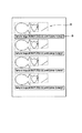
図16は、本発明の第10の実施例で用いるテストチャートの一例を示す図である。
【0228】
図16において、Y、M、Cのそれぞれはイエロー、マゼンタ、シアンの各色を示す。また、添え字の数字は、各色のたとえば最低濃度から最高濃度までを20段階に分けたときの何番目の濃度であるかを示すものである。
【0229】
オペレータは、LEDプリンタから出力された、図16に示すようなプリント97を、LEDプリンタの濃度測定部98に挿入する。濃度測定部98はプリント97の所定位置の濃度を測定し、測定データDmes[color][i]を変換特性作成部99に対して出力する。
【0230】
変換特性作成部99では、テストチャートのとおりの濃度の並びになった測定データが得られたかどうか等によって、測定データに異常(感光紙のカブリ、現像特性異常、オペレータによるテストチャートの挿入ミス等)がないかを調べ、異常がなければ次の処理へと進む。
【0231】
変換特性作成部99では、次の処理として、補正カーブ(変換特性)NewLut[color][i]および補正係数kc[color]を算出し、算出結果を不揮発性メモリ100に記憶する。補正カーブNewLut[color][i]および補正係数kc[color]の算出方法については後述する。
【0232】
これまで説明した処理で補正は完了する。以降、通常のプリントの際には、補正カーブNewLut[color][i]を信号変換部94にロードし、これを変換テーブルlut[color][i]として使用しプリントを実行する。
【0233】
なお、本実施例では、図16に示したようなY、M、Cの各色のステップチャートを用いたが、本発明はこれに限られるものではなく、たとえば、Y、M、Cの各色が混在したグレーのステップチャートをテストチャートとして用いるようにしてもよい。
【0234】
次に、変換特性作成部99において、補正カーブNewLut[color][i]および補正係数kc[color]を算出する処理について説明する。ここでは、説明を簡単にするため、1色について説明する。従って添え字の[color]は省略して示す。
【0235】
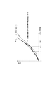
図17は、画像データと変換テーブルの出力値との関係すなわち補正カーブと、変換テーブルの出力値と測定された濃度との関係とを示す図である。
【0236】
ここで、テストチャートの各色のi番目の目標濃度、テストチャートを出力するための信号変換部94への入力値(TP信号)および濃度測定部98による測定濃度のそれぞれを、Dref[i]、pwm[i]およびDmes[i]とする。Dref[i]およびpwm[i]は、低濃度〜高濃度のチャート順に対応して定義されており、Dmes[i]は信号変換部94の入力値の順序に同期するように、各色チャートの主濃度を順に並べ替えたものとする。また、このテストチャートのプリントに用いた補正カーブをlut[256]とする。
【0237】
このとき、i番目の目標濃度を得るためのLUTの値をNewLut[i]とし、Dref[i]がj番目の測定濃度Dmes[j]とj+1番目の測定濃度Dmes[j+1]との間にあったとすると、図17に示す関係から、NewLut[i]は数3に示すようにして求められる。
【0238】
【数3】
【0239】
そして、これらの組データによって、信号変換部94の入力と出力との関係が離散的に求められ、中間値については補間することによって求められ、これによって新たな合成補正カーブを求めることができる。得られたカーブは、前述のように、所定の入力値(上記の例では144)での出力値を補正係数として不揮発メモリ100の所定の記憶領域に記憶され、さらに補正カーブも不揮発メモリ100の所定の記憶領域に記憶される。
【0240】
得られた補正カーブが前述のNewLut[color][i](1色分)となり、補正係数がNewLut[color][144]すなわちkc[color]である。
【0241】
なお、上記処理では目標濃度値Dref[i]の間隔は不均等でよいため、たとえば、ハイライト部分の間隔を他の部分よりも細かく設定して、ハイライト部分のカラーバランスがより安定するようにするのが好ましい。
【0242】
次に、本発明の第11の実施例について説明する。
【0243】
この第11の実施例は、LEDプリンタによるプリント結果を常に安定させるために必要となるLEDプリンタの内部における補正において、前述のようにチャネルごとの補正を行う場合に、より精度よく補正を行うものである。
【0244】
図18は、本発明の第11の実施例の制御系の構成を示すブロック図である。
【0245】
信号変換部101は、入力された画像データまたはTP信号を、内部のLUTに基づいて露光量データに変換する。ここで、TP信号(テストパターン信号)とはテストチャートをプリントするための画像データである。ドライバ102は信号変換部101からの露光量データに基づいて露光のための光源のLED103を点灯させる。プリント104はTP信号が信号変換部101に入力されることによって感光紙にプリントされたプリント結果である。濃度測定部105はプリント104上の所定の位置の濃度を測定し、測定データを出力する。変換特性作成部106は、濃度測定部105からの測定データおよび不揮発性メモリ107に記憶された各種データに基づいて、信号変換部101で用いるLUTを求め、信号変換部101に対して出力する。
【0246】
なお、たとえば、信号変換部101は図1に示したLBB26a、26b、26cであり、ドライバ102は図1に示したLDB30a、30b、30c、30d、30eであり、LED103は図1に示したLEDアレイ基板32a、32b、32c上に配列したLEDであり、濃度測定部105は図1に示した濃度計23であり、変換特性作成部106は図1に示したIPB−CPU6である。
【0247】
次に、この第11の実施例の動作について説明する。
【0248】
前述のように、チャネルごとの補正では、現像特性の変動をマスターチャネル補正によって補正し、感材すなわち感光紙の違いによる特性の違いをペーパーチャネル補正によって補正する。各補正データは不揮発性メモリ107に記憶される。以下、マスターチャネル(MCH)に対応する補正データを現像補正係数、ペーパーチャネル(PCH)に対応する補正データを感材補正カーブおよび感材補正係数として説明する。
【0249】
なお、この実施例では、後述のように、PCH用のテストチャートをプリントする際には、感材補正係数、感材デフォルト補正カーブおよび現像補正係数によって変換テーブルを生成し、MCH用のテストチャートをプリントする際および通常のプリント時には、感材補正カーブおよび現像補正係数によって変換テーブルを生成する。
【0250】
初めに、マスターチャネル補正に関して説明する。
【0251】
MCHは、主に現像機に起因する、感度、カラーバランスの変動を補正する。現像特性の変動は従来から知られているように、各色露光量の制御によってほぼ補正できる。言い換えれば、各色ごとのスカラー量として補正値を保持すればよい。このため、MCH値は各色ごとの係数値として保持する。
【0252】
MCHは、現像処理を同一にすることができる感材ごとに1つにすることができる。このため、1日に多種類の面質やサイズの異なる感材を使用する場合、感材ごとに現像特性の補正作業をいちいち行わずに、MCH補正を1度行えばよく、補正作業を減らせるという効果がある。MCHは、現像特性の変動を補正するためのチャネルであるため、たとえば1日に1度行えばよい。
【0253】
以下、本発明の第11の実施例におけるMCHの補正について説明する。
【0254】
まず、オペレータが操作パネルからMCH補正の実行を指示すると、テストチャートをプリントするために、信号変換部101にテストチャートプリント用の補正カーブTcLut[color][i]がロードされる。
【0255】
このテストチャートプリント用の補正カーブTcLut[color][i]は、不揮発性メモリ107に現在記憶されている、感材補正カーブPchLut[color][i]と現像補正係数mch[color]とを用いて数4によって算出されるものである。
【0256】
【数4】
【0257】
次に、信号変換部101にTP信号を入力し、TP信号が示す画像を、変換特性作成部106からロードした補正カーブTcLut[color][i]に基づいてプリントし、プリント104を出力する。
【0258】
図19は、本発明の第11の実施例のMCH補正で用いるテストチャートの一例を示す図である。
【0259】
図19において、Y、M、Cのそれぞれはイエロー、マゼンタ、シアンの各色を示し、kは3色を重ね合わせたグレーを示す。プリント104における各色は、変換特性TcLutが単調性を有しているとき、プリント濃度が数5に示す大小関係を満たすように配置される。
【0260】
【数5】
c0<c1<c2<c3<c4
m0<m1<m2<m3<m4
y0<y1<y2<y3<y4
なお、テストチャートにおいて、図19に示すように各色を配置することによって、たとえば図20に示すように各色を配置するのに比べて、補正の手間が少なくなるという効果がある。なお、図20は従来のテストチャートの一例を示す図である。
【0261】
オペレータは、LEDプリンタから出力された、図19に示したプリント104を、LEDプリンタの濃度測定部105に挿入する。濃度測定部105はプリント104の所定位置の濃度を測定し、測定データDmes[color][i]を変換特性作成部106に対して出力する。
【0262】
なお、本実施例では、濃度測定および測定濃度のチェックを、図19に示したプリント104の列ごとに行う。すなわち、オペレータがプリント104を濃度測定部105に挿入すると、濃度測定部105では図19に示した列r1(k0、m3、m2、m1、c3、c2、c1、y3、y2、y1、k0の列)のみを読み取って、測定濃度のチェックへと進む。
【0263】
測定濃度のチェックでは測定ミスの判定を行う。
【0264】
まず、プリント104の画像においてたとえば誤った列を読み取っていないかをチェックする(今回は、列r2(k0、y4、y0、m4、m0、c4、c0、k1、k2、k3、k0の列)が誤った列である)。これはテストチャートの各列の色配列を変えておけば容易に判定することができる。
【0265】
次に、感材の管理状態、履歴、現像機の汚れなどによる特性変動やカブリがないかを判定する。
【0266】
補正データを求める際、感材がかぶっていたり、局所的に特性が変化していたり、現像機が汚れていたりすると、正しい補正データが求められない。さらに、補正の方式次第ではその影響が次回以降の補正にまで及んでしまう。そこで、本実施例では、テストチャートの濃度を測定した段階で、補正データを求める計算を行う前に、この判定を行う。以下に、この判定の原理を説明する。
【0267】
列r1にはk0で示される同じ濃度示すグレーデータが複数ヶ所(図19では2ヶ所)にプリントされており、k0の位置による色ずれが許容値よりも大きい場合には、感材の管理状態等による特性変動またはカブリであると判定する。色ずれは、2ヶ所のk0のそれぞれのCMY濃度を(kc1,km1,ky1)、(kc2,km2,ky2)としたとき、A=|(km1−kc1)−(km2−kc2)|、B=|(km1−ky1)−(km2−ky2)|、色ずれ=(A2+B2)1/2によって求められる。
【0268】
上記のチェックにおいて異常がなかった場合、目標濃度の存在範囲についてチェックを行う。すなわち、各色濃度c1〜c3、m1〜m3、y1〜y3を判定する。MCHでは、C、M、Yの各色が誤差なくセットアップされたとき、目標濃度が上記3点のうちのいずれか2点間に含まれるようにプリントされている。この範囲に目標濃度が存在している場合には、濃度測定および測定濃度のチェックを終了する。一方、列r1の範囲に目標濃度が存在していない場合には、オペレータがプリント104を濃度測定部105に再度挿入し、列r2について濃度測定および測定濃度のチェックを行う。ただし、列r2の測定濃度のチェックの際には、目標濃度の存在範囲についてはチェックを行わない。列r2には列r1からさらに外側の低、高濃度を含む点がプリントされている。
【0269】
さらに、列間でもk0部の濃度から色シフトを見て、感材の管理状態、履歴による特性変動やカブリがないかを判定する。
【0270】
テストチャートを、図20に示したように、最低限補正に必要な情報を分散してしまうと、変動が少ない場合でもすべての列の濃度を読み取らねばならず、補正に要する時間、手間が、本実施例に比べて多くかかってしまう。また、図19に示したように、列r1といっしょに列r2をプリントしておけば、列r2が必要となったとき(ずれが大きいとき)に再度プリントする必要がなく、プリント時間の節約になる。
【0271】
なお、感材の管理状態、履歴による局所的な特性変動やカブリの判定は、k0のような同じパッチを複数用意しなくても可能である。たとえば、濃度の読み取りを複数ヶ所で位置をずらして行い、色シフト量を比較する方法や、チャートがグレーステップであればステップをほぼ均等に2列に分散して配置し、チャートを読み取ったときのグループ間での色シフト量を比較する方法等がある。
【0272】
変換特性作成部106では、次の処理として、現像補正係数mch[color]を算出し、算出結果が所定範囲内であれば不揮発性メモリ107に記憶する。一方、新たに求めた現像補正係数と今までの現像補正係数との比(以下、「現像補正係数の補正率」という)が一定値を越える場合などでは、現像補正係数の補正率に応じ、以下の(1)〜(3)のように、その後の処理を異ならせる。
(1) 現像補正係数の補正率が±20%未満のとき
算出結果の現像補正係数を不揮発性メモリ107に登録して完了する。
(2) 現像補正係数の補正率が±20%以上、±35%未満のとき
算出結果の現像補正係数を不揮発性メモリ107に登録するとともに、オペレータに対して再度補正を行うように促す。
(3) 現像補正係数の補正率が±35%以上のとき
算出結果の現像補正係数を不揮発性メモリ107に登録せず、オペレータに対して再度補正を行うように促す。なお、(3)を繰り返すようであれば、補正値の初期化を行い、再度補正を行うように、オペレータに対し促す。
【0273】
現像補正係数mch[color]の算出方法については後述する。
【0274】
これまで説明した処理で補正は完了する。以降、通常のプリントの際には、新たな現像補正係数mch[color]が現像特性変動の補正に用いられる。
【0275】
次に、変換特性作成部106において、現像補正係数mch[color]を算出する処理について説明する。
【0276】
テストチャートの列r1には各色主濃度が目標濃度0.64、0.76、0.90付近の設定値となる3段のパッチが記録されており、列r2には各色主濃度が目標濃度0.53、1.05付近の設定値となる2段のパッチが記録されている。セットアップ完了後、各階調でグレー濃度が維持されるよう、色ごとに設定値は異なってよい。
【0277】
特性のずれが大きく、列r1のプリント範囲に目標濃度が存在しない場合には、前述のように列r2のデータも用いる。列r2のデータを用いても範囲該の場合には外挿によって推定する。
【0278】
プリントしたテストチャートの各パッチの濃度測定を行い、目標濃度0.76がどの段とどの段の間に存在するかを求める。目標濃度としては、濃度0.7付近を選択すればよく、必ずしも0.76でなくてもよい。
【0279】
図21は、各色のチャートを濃度の低いほうから高いほうへ5段分並べて示す図であり、目標濃度が存在する範囲を説明する図である。
【0280】
図21において、矢印は測定濃度に基づいた目標濃度が存在するチャートの段位置を示しており、パッチ内の数字は各パッチの目標濃度を示している。
【0281】
以上の処理で目標濃度の付近の2点の濃度を決定することができた。以下、現像補正係数を算出する処理について説明する。まず、目標濃度付近の2点の濃度から補間によってMCH補正値を計算する。ここでは、説明を簡単にするため、1色について説明する。従って添え字の[color]は省略して示す。
【0282】
図22は、画像データと変換テーブルの出力値との関係すなわち補正カーブと、変換テーブルの出力値と測定された濃度との関係とを示す図である。
【0283】
目標濃度0.76の付近の2点の濃度のパッチを得るためのTP信号および当該パッチの測定濃度を、それぞれ{pwm[0]、pwm[1]}、{Dmes[0]、Dmes[1]}とする。目標濃度がテストチャートの範囲外のときには、最も近いパッチ2つの測定濃度を代わりとする。
【0284】
また、現像補正係数と後述するペーパーチャネル(PCH)の合成特性として得られるテーブルをTclut[256]とする。
【0285】
このとき、目標濃度を得るための補正カーブ上での値をlut_mchとすると、lut_mchは数6で求められる。
【0286】
【数6】
【0287】
【数7】
mch_new=lut_mch/Pchlut[pwm[ref]]
ここで、数4に示した関係を用いて整理すると、数8が得られる。
【0288】
【数8】
【0289】
次に、ペーパーチャネル(PCH)の補正に関して説明する。
【0290】
PCHは、感材の違い(たとえばロットの違い)によるばらつきを補正し、望ましい階調に設定する。PCHでは、デジタル処理の特徴を生かし、入力対出力濃度の関係が所定の階調になるような変換特性をチャネルとしてテーブル形式で保持する。補正データは感材種別に対応させて記憶する。
【0291】
また、PCHは、新しいペーパーをはじめて使用するときや、ペーパーのロットが変更されるときにセットアップを行い更新する。これから使用するペーパーに対するセットアップが1度もなされていないときは、デフォルト値として記憶されている初期テーブルからキャリブレーションを開始する。
【0292】
この際、デフォルトとして持つ補正カーブは、たとえば乳剤や面質に応じて複数用意しておいてもよく、感材種別に対応したデフォルトテーブルを不揮発性メモリ107から選択するようにしてもよい。
【0293】
以下、本発明の第11の実施例におけるPCHの補正について説明する。
【0294】
まず、オペレータが操作パネルからPCH補正の実行を指示すると、テストチャートをプリントするために、信号変換部101にテストチャートプリント用の補正カーブTcLut[color][i]がロードされる。
【0295】
このテストチャートプリント用の補正カーブTcLut[color][i]は、不揮発性メモリ107に現在記憶されている、感材補正係数Pch[color]と感材補正デフォルトカーブDefPchLut[color][i]と現像補正係数mch[color]とを用いて数9によって算出されるものである。
【0296】
【数9】
【0297】
また、kは色ごとに異なる定数であり、DefPchLutの特定入力値に対する出力であり、本実施例では8ビット入力に対し、入力値144でグレー濃度0.8付近が得られる設定にしており、この入力で正規化する。従って、k[color]は数10で表される。
【0298】
【数10】
k[color]=DefPchLut[color][144]
なお、初回は補正カーブTcLut[color][i]として感材補正デフォルトカーブDefPchLut[color][i]をそのまま用いる。
【0299】
次に、信号変換部101にTP信号を入力し、TP信号が示す画像を、変換特性作成部106からロードした補正カーブTcLut[color][i]に基づいてプリントし、プリント104を出力する。
【0300】
このPCH補正で用いるテストチャートは、たとえば、図16に示したテストチャートと同様の20段程度のステップチャートでよいので、ここでは図16を参照して説明する。
【0301】
オペレータは、LEDプリンタから出力された、図16に示したプリント104を、LEDプリンタの濃度測定部105に挿入する。濃度測定部105はプリント104の所定位置の濃度を測定し、測定データDmes[color][i]を変換特性作成部106に対して出力する。
【0302】
変換特性作成部106は、測定データを判定し、異常(ペーパーのカブリ、現像特性異常、ユーザーの誤操作によるデータ異常等)がないかを調べた後、以降の処理へと進む。
【0303】
変換特性作成部106では、次の処理として、変換特性(補正カーブ)を算出し、補正カーブおよび補正係数分の形で、結果を不揮発性メモリ107にPCH値として登録する。ここで、補正係数分はPch[color]=PchLut[color][144]として決定する。感材補正カーブPchLut[color][i]は算出した補正カーブである。
【0304】
以降、通常プリントの際は、たとえばペーパーカートリッジに印刷された、ペーパーのロット・種別などを識別するコード等から、同じペーパーと判定できる場合には、不揮発性メモリ107に登録されている補正カーブPchLut[color][i]をその感材用のPCHとして使用する。
【0305】
再度補正を行う場合には上記処理を繰り返す。テストプリントの再には、現像補正係数と感材補正係数と感材補正デフォルトカーブとから生成された変換テーブルを信号変換部101にセットして、たとえば図16に示した20段程度のYMCチャートをプリントする。このときの変換テーブルは数11によって算出される。
【0306】
【数11】
【0307】
図23は、画像データと変換テーブルの出力値との関係すなわち補正カーブと、変換テーブルの出力値と測定された濃度との関係とを示す図である。
【0308】
ここで、テストチャートの各色のi番目の目標濃度、テストチャートを出力するための信号変換部101への入力値(TP信号)、目標濃度および濃度測定部105による測定濃度のそれぞれを、Dref[i]、pwm[i]およびDmes[i]とする。また、このテストチャートのプリントに用いた補正カーブをTclut[256]とする。
【0309】
このとき、i番目の目標濃度を得るためのLUTの値をlut_pch2[i]とし、目標濃度Dref[i]がj番目の測定濃度Dmes[j]とj+1番目の測定濃度Dmes[j+1]との間にあったとする。
【0310】
補正カーブTclut[i]は数12で表される。
【0311】
【数12】
【0312】
【数13】
Tclut[i]=Tc_PchLut[i]×mch
また、図23に示す関係から、lut_pch2[i]は、数14に示すようにして求められる。
【0313】
【数14】
【0314】
【数15】
pch2[i]=lut_pch2[i]/mch
また、数14と数15とから数16のようになる。
【0315】
【数16】
【0316】
【数17】
【0317】
そして、これらの組データによって、信号変換部101の入力と出力との関係が離散的に求められ、中間値については補間することによって求められ、これによって新たなPCHの合成補正カーブを求めることができる。
【0318】
なお、上記処理では目標濃度値Dref[i]の間隔は不均等でよいため、たとえば、ハイライト部分の間隔を他の部分よりも細かく設定して、ハイライト部分のカラーバランスがより安定するようにするのが好ましい。
【0319】
得られた補正カーブを感材補正カーブPchLut[color][i]として不揮発メモリ107を更新し、不揮発メモリ107の感材補正係数Pch[color]をPchLut[color][144]の値で更新する。
【0320】
次に、本発明の第12の実施例について説明する。
【0321】
ところで、上述の各実施例で説明したような補正を行ったとしても、目標濃度からある程度以上ずれる場合には、露光・特性補正系に問題があるのか、それとも現像系に問題があるのかを判定する必要がある。なぜならば、現像系に問題がある場合、露光量補正によって補正できる分には限界があるからである。
【0322】
上述の各実施例で説明したような補正を行うことによって、現像液、ペーパーロット間の違いなどの補正が可能である。しかしながら、現像液が劣化してしまった場合、プリント結果における最高濃度が低下し、露光量の補正(露光時間やLUTの補正)では補正しきれなくなってしまう。最高濃度が低下した場合の問題は、露光量が何等かの要因で低下しているのが原因なのか、現像液の劣化が原因なのかを容易に切り分けできない点にある。
【0323】
従来から、このような場合にはコントロールストリップを流す方法が知られている。ところが、このコントロールストリップを流す方法の場合、特別に露光された感光材料(ペーパー、印画紙)を用いるため、正確である反面、手間がかかるという問題がある。
【0324】
この第12の実施例は現像液の劣化を判定することができるものであり、本実施例によれば、コントロールストリップを用意しなくても、簡便な方法で、適切なトラブルシューティングが行える。
【0325】
図24は、本発明の第12の実施例における処理のフローチャートを示す図である。
【0326】
まず、オペレーターがLEDプリンタの操作パネル21から現像液劣化判定用チャートの出力を指示すると、図25に示すようなチャートがプリントされる(E−1)。
【0327】
図25は、本発明の第12の実施例において用いる現像液劣化判定用チャートを示す図である。
【0328】
図25において、Y、M、CはそれぞれB、G、Rの単独色でベタ露光されたパッチであり、KはR、G、Bの3色でベタ露光されたパッチである。
【0329】
次に、オペレータは、図25に示した現像液劣化判定用チャートを濃度計23に挿入し、濃度計23では現像液劣化判定用チャートの各パッチの濃度を測定する(E−2)。このとき、図25に示した現像液劣化判定用チャートのパッチCについてはC濃度、パッチMについてはM濃度、パッチYについてはY濃度、パッチKについてはC、M、Yの3色の濃度を測定する。
【0330】
次に、濃度のチェックを行う(E−3)。
【0331】
具体的には、パッチC、パッチM、パッチYのC濃度、M濃度、Y濃度と、パッチKの黒濃度とを比較する。現像液が劣化すると、露光量は十分なのにも関わらず、感材が十分に現像されず、濃度が低下する。この現象は、印画紙の上層が発色しているほど顕著なため、黒の最高濃度付近が最も顕著に現れる。すなわち、印画紙において各色に発色する層のうちたとえばYに発色する層が最下層であった場合、現像液が劣化していると、パッチC、パッチMおよびパッチYの単色ではそれぞれ所定の濃度が十分に得られていても、パッチKでは最下層のY濃度が十分にあがらずに青みがかった黒になってしまう。
【0332】
このため、ステップ(E−3)における判定条件としては、CMY濃度が所定の濃度に達しており、且つ黒のY濃度が所定値以下であることが挙げられる。この条件で判定が行われ(E−4)、正常である場合には、現像液が劣化していない旨をたとえば操作パネル21のLCD22にメッセージ表示する(E−5)。ステップ(E−4)で異常の場合すなわち上記条件に該当する場合には、現像液の劣化の可能性が高いので、その旨をたとえば操作パネル21のLCD22にメッセージ表示する(E−6)。
【0333】
次に、本発明の第13の実施例について説明する。
【0334】
この第13の実施例は、第12の実施例と同様に、現像液の劣化を判定することができるものであり、本実施例によれば、コントロールストリップを用意しなくても、簡便な方法で、適切なトラブルシューティングが行える。
【0335】
第12の実施例では、露光量を確認するために図25に示したようなチャートをプリントしたが、本実施例はこの点に違いがある。すなわち、この第13の実施例では、印画紙に外光によるカブリ露光が行えるように、たとえばLEDプリンタの筐体に窓を設け、この窓からの外光によって印画紙を所定時間かぶらせ、このかぶらせた印画紙を現像し、現像結果を現像液劣化の判定に用いる。
【0336】
図26は、本発明の第13の実施例における処理のフローチャートを示す図である。
【0337】
まず、LEDプリンタの筐体に設けた窓(シャッタ等によって自動または手動で開閉可能にしておくとよい)からの外光によって印画紙を所定時間かぶらせる(F−1)。この所定時間は、カブリが十分に行われるだけの時間に設定するのがよい。
【0338】
LEDプリンタは、その後、かぶらせた印画紙を現像し(F−2)、外部に排出する。オペレータは、排出された印画紙を濃度計23に挿入し、濃度計23ではカブリ露光、現像を行った印画紙の濃度を測定する(F−3)。
【0339】
次に、濃度のチェックを行う(F−4)。本実施例では、印画紙において各色に発色する層のうちたとえばYに発色する層が最下層であった場合、たとえばC濃度が所定値以上であり、且つY濃度が所定値以下である場合に、現像液劣化の可能性が高いと判定する。
【0340】
判定結果(F−5)が、正常である場合には、現像液が劣化していない旨をたとえば操作パネル21のLCD22にメッセージ表示する(F−6)。ステップ(F−5)で異常の場合には、現像液の劣化の可能性が高いので、その旨をたとえば操作パネル21のLCD22にメッセージ表示する(F−7)。
【0341】
ここでは、筐体に設けた窓からの外光によってカブリ露光行う方式を説明したが、その趣旨は、記録光源とは別の光源によって、印画紙に十分カブリ露光を与えることであり、外光による露光の代わりにたとえばプリンタ内にランプ等のLEDとは別の光源を配置し、この光源によって印画紙を所定時間カブリ露光させてもよい。
【0342】
次に、本発明の第14の実施例について説明する。
【0343】
LEDプリンタにおいて、プリントを行なう感光紙として長尺記録紙を用いた場合、上述のように、露光に先立ち記録紙を所望のサイズにカットする必要がある。
【0344】
このような方式において、ホストコンピュータから一旦はプリント開始の指示がきて記録紙を所望のサイズにカットした後、プリント中止の指示があった場合、従来は、カット済み記録紙に対して露光がされていないにもかかわらず、そのカット済み記録紙をそのまま排出してしまっていた。このため、従来は記録紙の無駄が生じてしまうという問題があった。
【0345】
そこで、この第14の実施例では、このような記録紙の無駄を極力解消することを目的とする。
【0346】
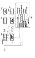
図27は、本発明の第14の実施例の構成を示すブロック図である。
【0347】
図27において、ホストコンピュータ1は、LEDプリンタ2に対してプリント開始を指示する画像記録開始指示手段110と、LEDプリンタ2に対して今回のプリントに必要な記録紙のサイズを送信する記録紙切断長指示手段111と、LEDプリンタ2に対して画像データを送信する画像データ送信手段112と、LEDプリンタ2に対してプリント中止を指示する画像記録中止指示手段113とを有する。また、LEDプリンタ2は、ホストコンピュータ1からのデータを受けてLEDプリンタ2の各部の動作を制御する制御手段114と、プリントに用いられる記録紙である長尺記録紙115と、長尺記録紙115を引き出して給紙する給紙手段116と、カットされた長尺記録紙115を排紙する排紙手段117と、引き出された長尺記録紙115を所望のサイズでカットする記録紙切断手段118と、カットされた長尺記録紙115に画像を記録する画像記録手段119とを有する。
【0348】
なお、たとえば、制御手段114は図1に示したIPB−CPU6であり、給紙手段116は給紙ローラーであり、排紙手段117は排紙ローラーであり、記録紙切断手段118はペーパーカッターであり、画像記録手段119は図1に示した回転ドラム36およびLEDアレイ32a、32b、32c等の露光プロセスに用いられる構成である。
【0349】
次に、この第14の実施例の動作について説明する。
【0350】
まず、オペレータがホストコンピュータ1を操作して、プリントを指示すると、ホストコンピュータ1の画像記録開始指示手段110は、LEDプリンタ2に対してプリント開始を指示する。また、記録紙切断長指示手段111は、LEDプリンタ2に対して記録紙のサイズを指示する。さらに、画像データ送信手段112は、LEDプリンタ2に対して画像データの送信を開始する。
【0351】
これらの指示を受けたLEDプリンタ2の制御手段114は、給紙手段116および記録紙切断手段118に対して、記録紙切断長指示手段111から指示されたサイズに基づいて長尺記録紙115を引出してカットするように指示する。この指示を受けた給紙手段116は長尺記録紙115を必要な長さだけ引き出し、その時点で記録紙切断手段118が長尺記録紙115をカットする。
【0352】
次に、制御手段114は、画像データ送信手段112から受け取った画像データに基づいてカット済み記録紙120に画像記録するように画像記録手段119に対して指示するわけだが、この画像記録を行う前にホストコンピュータ1の画像記録中止指示手段113からプリント中止の指示を受けた場合には、画像記録手段119に対して画像記録の指示を行わないようにする。
【0353】
なお、制御手段114が画像記録中止指示手段113からプリント中止の指示を受けたのが、制御手段114が画像記録手段119に対して画像記録の指示を行った後だとしても、カット済み記録紙120にまだ画像記録がされていない状態であれば、制御手段114は画像記録手段119に対して画像記録の中止を指示し、本実施例が実現可能である。
【0354】
このとき、カット済み記録紙120にはまだ画像記録をしていないため、カット済み記録紙120の再利用が可能である。そこで、本実施例では、このように、ホストコンピュータ1から一旦はプリント開始の指示がきて長尺記録紙115を所望のサイズにカットした後、ホストコンピュータ1からプリント中止の指示があった場合、カット済み記録紙120を排出せず、LEDプリンタ2内に保持して次のプリント開始の指示を待つ。
【0355】
この状態で、ホストコンピュータ1の画像記録開始指示手段110からLEDプリンタ2に対して次のプリント開始が指示された場合、制御手段114は、記録紙切断長指示手段111からLEDプリンタ2に対して新たに指示された記録紙のサイズと、LEDプリンタ2内に保持しているカット済み記録紙120のサイズとを比較する。
【0356】
この記録紙サイズの比較の結果、同じサイズであった場合には、制御手段114は、LEDプリンタ2内に保持しているカット済み記録紙120に対して、新たな画像データを記録するように、画像記録手段119に指示する。画像記録手段119によって、LEDプリンタ2内に保持していたカット済み記録紙120に対する画像記録が完了したならば、制御手段114は排紙手段117を制御して画像記録済みの記録紙を排紙する。
【0357】
また、上述の記録紙サイズの比較の結果、記録紙切断長指示手段111からLEDプリンタ2に対して新たに指示された記録紙のサイズが、LEDプリンタ2内に保持しているカット済み記録紙120のサイズよりも大きい場合には、保持しているカット済み記録紙120に対して新たな画像を記録することができないので、制御手段114は、排紙手段117を制御してカット済み記録紙120をそのまま排紙し、長尺記録紙115を新たなサイズでカットして新たな画像の記録を実行する。
【0358】
さらに、上述の記録紙サイズの比較の結果、記録紙切断長指示手段111からLEDプリンタ2に対して新たに指示された記録紙のサイズが、LEDプリンタ2内に保持しているカット済み記録紙120のサイズよりも小さい場合には、以下の3通りの処理のうちから、たとえばオペレータが選択することができるようにしておくとよい。これは、プリント結果の用途によって、画像が欠けないで記録されればよいような場合やサイズが一致していなければいけないような場合等があるため、オペレータが処理を選択することができるようにしておくと便利だからである。
(1)LEDプリンタ2内に保持しているカット済み記録紙120のほうが新たに指示された記録紙のサイズよりも大きいので、新たな画像はカット済み記録紙120に入りきるが、完全に一致するサイズではないので、カット済み記録紙120には画像を記録せずに排紙する。
(2)LEDプリンタ2内に保持しているカット済み記録紙120に新たな画像を記録して排紙する。
(3)LEDプリンタ2内に保持しているカット済み記録紙120を、新たに指示された記録紙のサイズにカットし、このカットされた記録紙に新たな画像を記録して排紙する。
【0359】
ところで、カット済み記録紙120をLEDプリンタ2内に長時間保持していると、雰囲気や遮光の度合いによってカット済み記録紙120の特性が経時劣化するおそれがあるし、記録紙が薬品を含有する場合には、給紙手段116、排紙手段117または画像記録手段等の周辺構成に悪影響を与えるおそれがある。このため、カット済み記録紙120をLEDプリンタ2内に保持している時間が所定時間に達したならば、画像記録をせずに強制的に排紙するのが望ましい。このとき、カット済み記録紙120を強制排紙するまでの所定時間は、たとえばオペレータが設定し、変更可能にしておくのがよい。
【0360】
次に、本発明の第15の実施例について説明する。
【0361】
第15の実施例も、第14の実施例と同様に、記録紙の無駄を極力解消することを目的とするものである。
【0362】
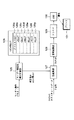
図28は、本発明の第15の実施例の構成を示すブロック図である。
【0363】
図28において、ホストコンピュータ1は、LEDプリンタ2に対してプリント開始を指示する画像記録開始指示手段110と、LEDプリンタ2に対して画像データを送信する画像データ送信手段112と、LEDプリンタ2に対してプリント中止を指示する画像記録中止指示手段113とを有する。また、LEDプリンタ2は、ホストコンピュータ1からのデータを受けてLEDプリンタ2の各部の動作を制御する制御手段114と、プリントに用いられる記録紙である長尺記録紙115と、長尺記録紙115を引き出して給紙する給紙手段116と、カットされた長尺記録紙115を排紙する排紙手段117と、引き出された長尺記録紙115を所望のサイズでカットする記録紙切断手段118と、カットされた長尺記録紙115に画像を記録する画像記録手段119とを有する。また、本実施例においては、LEDプリンタ2の制御手段114が、画像データ送信手段112から受けた画像データに基づいて今回のプリントに必要な記録紙のサイズを決定する記録紙切断長決定手段121を有する。
【0364】
なお、たとえば、制御手段114は図1に示したIPB−CPU6であり、給紙手段116は給紙ローラーであり、排紙手段117は排紙ローラーであり、記録紙切断手段118はペーパーカッターであり、画像記録手段119は図1に示した回転ドラム36およびLEDアレイ32a、32b、32c等の露光プロセスに用いられる構成である。
【0365】
次に、この第15の実施例の動作について説明する。
【0366】
まず、オペレータがホストコンピュータ1を操作して、プリントを指示すると、ホストコンピュータ1の画像記録開始指示手段110は、LEDプリンタ2に対してプリント開始を指示する。また、画像データ送信手段112は、LEDプリンタ2に対して画像データの送信を開始する。
【0367】
プリント開始の指示および画像データを受けたLEDプリンタ2の制御手段114では、記録紙切断長決定手段121によって、受信した画像データの大きさに基づいて今回のプリントに必要な記録紙のサイズを決定する。
【0368】
そして、制御手段114は、給紙手段116および記録紙切断手段118に対して、記録紙切断長決定手段121によって決定したサイズに基づいて長尺記録紙115を引出してカットするように指示する。この指示を受けた給紙手段116は長尺記録紙115を必要な長さだけ引き出し、その時点で記録紙切断手段118が長尺記録紙115をカットする。
【0369】
次に、制御手段114は、画像データ送信手段112から受け取った画像データに基づいてカット済み記録紙120に画像記録するように画像記録手段119に対して指示するわけだが、この画像記録を行う前にホストコンピュータ1の画像記録中止指示手段113からプリント中止の指示を受けた場合には、画像記録手段119に対して画像記録の指示を行わないようにする。
【0370】
なお、制御手段114が画像記録中止指示手段113からプリント中止の指示を受けたのが、制御手段114が画像記録手段119に対して画像記録の指示を行った後だとしても、カット済み記録紙120にまだ画像記録がされていない状態であれば、制御手段114は画像記録手段119に対して画像記録の中止を指示し、本実施例が実現可能である。
【0371】
このとき、カット済み記録紙120にはまだ画像記録をしていないため、カット済み記録紙120の再利用が可能である。そこで、本実施例では、このように、ホストコンピュータ1から一旦はプリント開始の指示がきて長尺記録紙115を所望のサイズにカットした後、ホストコンピュータ1からプリント中止の指示があった場合、カット済み記録紙120を排出せず、LEDプリンタ2内に保持して次のプリント開始の指示を待つ。
【0372】
この状態で、ホストコンピュータ1の画像記録開始指示手段110からLEDプリンタ2に対して次のプリント開始が指示された場合、制御手段114は、記録紙切断長決定手段121が新たな画像データに基づいて決定したサイズと、LEDプリンタ2内に保持しているカット済み記録紙120のサイズとを比較する。
【0373】
この記録紙サイズの比較の結果、同じサイズであった場合には、制御手段114は、LEDプリンタ2内に保持しているカット済み記録紙120に対して、新たな画像データを記録するように、画像記録手段119に指示する。画像記録手段119によって、LEDプリンタ2内に保持していたカット済み記録紙120に対する画像記録が完了したならば、制御手段114は排紙手段117を制御して画像記録済みの記録紙を排紙する。
【0374】
また、上述の記録紙サイズの比較の結果、記録紙切断長決定手段121が新たな画像データに基づいて決定したサイズが、LEDプリンタ2内に保持しているカット済み記録紙120のサイズよりも大きい場合には、保持しているカット済み記録紙120に対して新たな画像を記録することができないので、制御手段114は、排紙手段117を制御してカット済み記録紙120をそのまま排紙し、長尺記録紙115を新たなサイズでカットして新たな画像の記録を実行する。
【0375】
さらに、上述の記録紙サイズの比較の結果、記録紙切断長決定手段121が新たな画像データに基づいて決定したサイズが、LEDプリンタ2内に保持しているカット済み記録紙120のサイズよりも小さい場合には、以下の3通りの処理のうちから、たとえばオペレータが選択することができるようにしておくとよい。これは、プリント結果の用途によって、画像が欠けないで記録されればよいような場合やサイズが一致していなければいけないような場合等があるため、オペレータが処理を選択することができるようにしておくと便利だからである。
(1)LEDプリンタ2内に保持しているカット済み記録紙120のほうが新たに決定された記録紙のサイズよりも大きいので、新たな画像はカット済み記録紙120に入りきるが、完全に一致するサイズではないので、カット済み記録紙120には画像を記録せずに排紙する。
(2)LEDプリンタ2内に保持しているカット済み記録紙120に新たな画像を記録して排紙する。
(3)LEDプリンタ2内に保持しているカット済み記録紙120を、新たに決定された記録紙のサイズにカットし、このカットされた記録紙に新たな画像を記録して排紙する。
【0376】
ところで、カット済み記録紙120をLEDプリンタ2内に長時間保持していると、雰囲気や遮光の度合いによってカット済み記録紙120の特性が経時劣化するおそれがあるし、記録紙が薬品を含有する場合には、給紙手段116、排紙手段117または画像記録手段等の周辺構成に悪影響を与えるおそれがある。このため、カット済み記録紙120をLEDプリンタ2内に保持している時間が所定時間に達したならば、画像記録をせずに強制的に排紙するのが望ましい。このとき、カット済み記録紙120を強制排紙するまでの所定時間は、たとえばオペレータが設定し、変更可能にしておくのがよい。
【0377】
なお、上述の第14および第15の実施例では、画像記録中止指示手段113がホストコンピュータ1に設けられているとしたが、本発明はこれに限らず、LEDプリンタ2に画像記録中止指示手段を設けてもよい。
【0378】
次に、本発明の第16の実施例について説明する。
【0379】
ここまでの各実施例においては、画像形成の際に補正が必要となる要因のそれぞれをチャネルと呼んでこのチャネルごとに補正を行うようにし、現像機が原因の変動を補正するための補正量を求めるマスターチャネル補正と、感光紙の面質やロットごとのばらつきが原因の変動を補正するための補正量を求めるペーパーチャネル補正とについて説明した。この第16の実施例では、このような画像の変動を補正するチャネルのほかに、ユーザーの好みによって画像を変化させることができるユーザーチャネル(以下「UCH」ともいう)を設けている。
【0380】
従来は、このユーザーチャネルにおいて、画像全体の濃度を濃くしたり、薄くしたりすることはできたが、これはすべての濃度域(入力域)に対して行うものであった。
【0381】
図29は、従来のユーザーチャネルにおいて、入力された画像データのレベルと出力する画像データのレベルとの関係を示す図である。
【0382】
図29においてkはユーザーが指定するパラメータである。k=0のときには入力=出力となり、この場合、ユーザーチャネルによる補正が行われないことになる。また、たとえばユーザーがパラメータkに1を指定した場合には、ユーザーチャネルにおいて、入力された画像データのレベルを、図29に示すk=1の直線に基づいて高めて出力する。
【0383】
図29に示すように、従来はユーザーがパラメータkを指定することによってユーザーの好みの濃度を得ることができたが、このパラメータkによって変えることができるのは入力画像信号のレベルの全範囲にわたって露光量を変化させることのみであった。このため、従来のユーザーチャネルは、たとえば特定色のみを補正したい場合や特定濃度域のみを補正したいような場合には効果が得られないものであった。
【0384】
そこで、この第16の実施例では、たとえば特定の色の特定の濃度範囲のみについて濃度の調整を行うことができるLEDプリンタを提供することを目的とする。
【0385】
図30は、本発明の第16の実施例の制御系の構成を示すブロック図である。
【0386】
ユーザー特定色補正計算部122は、後述するユーザーが入力したユーザー操作パラメータと、UCH(ユーザーチャネル)用LUTとに基づき、所定の重み付けを行った変換特性f[col][i]を生成する。ユーザー特定色補正部123は、ユーザー特定色補正計算部122が生成した変換特性をロードし、入力された画像データをロードした変換特性fに基づいて補正して出力する。画像記録部124は、ユーザー特定色補正部123が出力した画像データに基づいて感光紙に画像記録を行う。
【0387】
なお、たとえば、ユーザー特定色補正計算部122は図1に示したIPB−CPU6であり、ユーザー特定色補正部123は図1に示したLBB26a、26b、26cであり、画像記録部124は図1に示したLEDアレイ基板32a、32b、32cである。
【0388】
次に、この第16の実施例の動作について説明する。
【0389】
まず、オペレータが操作パネル21からユーザーチャネルの補正の実行を指示すると、LEDプリンタ2はUCH用テストチャートをプリントする。
【0390】
図31は、本発明の第16の実施例で用いるテストチャートの一例を示す図である。
【0391】
このUCH用テストチャートは、CMYの3色を合成して作成したグレーチャートであり、図31に示すように、8ビットで表される256通りの画像データのレベルiのうちの20通り(20段)についてプリントしたものである。
【0392】
この20段のパッチの中には、画像データの濃度の最小値と最大値、すなわち、3色ともにレベルi=0のパッチと3色ともにレベルi=255のパッチが含まれるのが望ましい。UCH用テストチャートの一例としては、たとえばレベルi=(0、4、8、18、36、54、72、90、108、126、144、162、180、198、216、226、234、244、250、255)(3色ともに同レベル)の20個のパッチがプリントされたものにすればよい。
【0393】
また、このUCH用テストチャートは、ユーザー特定色補正部123において入力=出力となるUCHの補正が何らされていない状態でプリントされる。
【0394】
ユーザーは、プリントされたUCH用テストチャートを見て、色や濃度を調整したい段やその程度を、ユーザー操作パラメータとして、LEDプリンタ2に対して入力する。この入力の方法は、ホストコンピュータ1上で入力してSCSIによってLEDプリンタ2に対して送信するようにしてもよいし、LEDプリンタ2の操作パネル21から直接入力するようにしてもよい。入力されたユーザー操作パラメータはたとえば図1に示したメモリ9に記憶される。
【0395】
ここで色をcol、UCH用テストチャート中のパッチの段をjとしたとき、ユーザーによるユーザー操作パラメータの入力によって、補正しない段も含め、各色、各段に対応する微修正データk=fine[col][j]が設定される。微修正データの値は、該当する段でのユーザー操作パラメータである。
【0396】
以降の説明では、j+1段のパッチのシアン濃度をやや薄くしたい場合について説明するが、複数の段について、また複数色について補正を行う場合についても同様の処理を複数行うものである。
【0397】
図32は、ユーザー操作パラメータについて一覧に示す表図である。
【0398】
この図32は、j+1段のパッチのシアン濃度をやや薄くしたい場合のユーザー操作パラメータを示すものである。j+1段のシアン濃度の項はやや薄くするために−1となり、他の項については修正しないため0となっている。
【0399】
図33は、UCH用LUTの一例を示す図である。
【0400】
UCH用LUTは、図33に示すように、ユーザー操作パラメータkに対応して複数用意され、たとえば図1に示したメモリ9に記憶されている。
【0401】
ユーザー特定色補正部122にロードする変換特性f[col][i](colは色、iは入力レベル)は、前述のように、ユーザー特定色補正計算部123において計算される。
【0402】
ユーザー特定色補正計算部123では、UCH用テストチャートの各段ごとに、ユーザー操作パラメータに対応したUCH用LUTの値を選択する。ただし、UCH用テストチャートの各段は、画像データの入力レベルのすべてに対して設けられたものではないので、ユーザーが補正を指示した段とその前後の段との間を補間する必要がある。本実施例では、この段と段との間においてユーザー操作パラメータに対して所定の重み付けをして用いることによって補間する。ここでの重みwは、たとえば数18のように表される。
【0403】
【数18】
w=(r[j+1]−i)/(r[j+1]−r[j])
数18において、r[j]はj段における入力を示す。このとき、重みwは図34に示すようになる。
【0404】
図34は、本発明の第16の実施例における重みwの一例を示す図である。
【0405】
なお、重みwは、ユーザーが補正を指示した段で1となり、ユーザーが補正を指示しない段で0となればよいので、別の例として、図35に示すような形のものでもよい。
【0406】
図35は、本発明の第16の実施例における重みwの例であって、図34とは別の例を示す図である。
【0407】
ここで、ユーザー操作パラメータと重みとの関係についてさらに説明する。
【0408】
図36は、本発明の第16の実施例における、ユーザー操作パラメータと重みとの関係について説明する図である。
【0409】
図32に示したようなユーザー操作パラメータがユーザーから入力された場合、シアンの変換特性f[col][i](col=シアン)を作成するとき、図36に示すように、j+1段に対応する入力r[j+1]ではユーザー操作パラメータは−1が選択され、j段およびj+2段ではユーザー操作パラメータは0が選択される。いま、ユーザー操作パラメータに対応する、入力全域に対するUCH用LUTをuch[col][i]とすると、その中間、入力iがr[j]≦i≦r[j+1]の範囲であれば、変換特性f[col][i]として、j段ではuch[fine[col][j]][i]が選択され、j+1段ではuch[fine[col][j+]][i]が選択される(すなわち、重み1)。またj段とj+1段との間では、重みに従った特性になるように、変換特性f[col][i]は数19に示すようになる。
【0410】
【数19】
【0411】
図37は、図32に示したユーザー操作パラメータが指定された場合の、シアンについての変換特性の一例を示す図である。
【0412】
以上説明した処理によって、ユーザー特定色補正部122における入出力の新たな変換特性である階調変換カーブが生成できる。
【0413】
次回以降にユーザーチャネルの設定を行う場合には、すでに設定されているユーザー操作パラメータに変更を追加するか、新規にユーザー操作パラメータを設定するかを問い合わせ、ユーザー操作パラメータの変更を追加する場合には、すでに記憶してあるユーザー操作パラメータに応じた変換特性をユーザー特定色補正部122にロードしてUCH用テストチャートをプリントし、新規にユーザー操作パラメータを設定する場合には、初回と同様にユーザー特定色補正部122において入力=出力としてUCH用テストチャートをプリントする。
【0414】
以上説明したように、この第16の実施例によれば、ユーザーが変更したい濃度の範囲、色の範囲を簡単に指定することができ、その指定と全階調に対する変換特性とから階調の連続性を保ったまま、部分的な階調の変換を行うことができる。
【0415】
次に、本発明の第17の実施例について説明する。
【0416】
本実施例も、第16の実施例と同様に、ユーザーチャネル補正において特定の色や特定範囲の階調のみを補正しようとするものである。ただ、第16の実施例ではUCH用テストチャートとして20段のグレーチャートを用いたが、本実施例ではCMYの各色のそれぞれについて5段ずつで合計125(5×5×5)段のカラーチャートを用いる。
【0417】
図38は、本発明の第17の実施例の制御系の構成を示すブロック図である。
【0418】
ユーザー特定色補正計算部125は、ユーザーが入力したユーザー操作パラメータと、UCH用LUT126とに基づき、補正済みUCH用LUTを生成する。
【0419】
UCH用LUT126は、本実施例においては、3色のそれぞれについて9点ずつ合計9×9×9個の色変換情報を有するテーブルであり、デフォルトLUT126aはデフォルトの色変換特性についてのテーブル、+CLUT126bはデフォルトに対して色Cを増量した色変換特性についてのテーブル、−CLUT126cはデフォルトに対して色Cを減量した色変換特性についてのテーブル、+MLUT126dはデフォルトに対して色Mを増量した色変換特性についてのテーブル、−MLUT126eはデフォルトに対して色Mを減量した色変換特性についてのテーブル、+YLUT126fはデフォルトに対して色Yを増量した色変換特性についてのテーブル、−YLUT126gはデフォルトに対して色Yを減量した色変換特性についてのテーブルである。
【0420】
なお、本実施例では9×9×9個の格子点の色変換情報を有するLUTを用いるが本発明はこれに限られるものではなく、たとえば17×17×17や33×33×33であってもよい。
【0421】
本実施例におけるUCH用テストチャートは、UCH用LUT126の9×9×9個の格子点に対応する色変換情報を格子点1つおきにプリントするものである。
【0422】
色変換部127は、ユーザー特定色補正計算部125から9×9×9の補正済みUCH用LUTをロードし、この補正済みUCH用LUTに基づいて、入力された(r,g,b)形式の画像データを(c,m,y)形式の画像データに変換して出力する。
【0423】
信号変換部128は、入力された画像データに基づいてLED130を点灯させる露光量データを求め、ドライバ129に対して出力する。ドライバ129は、信号変換部128からの露光量データに基づいて露光のための光源のLED130を点灯させる。プリント131は、5×5×5のテストチャートデータが色変換部127に入力されることによって感光紙にプリントされたプリント結果である。
【0424】
なお、たとえば、ユーザー特定色補正計算部125は図1に示したIPB−CPU6であり、UCH用LUT126は図1に示したメモリ9に記憶したテーブルであり、色変換部127は図1に示した色変換部8であり、信号変換部128は図1に示したLBB26a、26b、26cであり、ドライバ129は図1に示したLDB30a、30b、30c、30d、30eであり、LED130は図1に示したLEDアレイ基板32a、32b、32c上に配列したLEDである。
【0425】
次に、この第17の実施例の動作について説明する。
【0426】
まず、オペレータが操作パネル21からユーザーチャネルの補正の実行を指示すると、LEDプリンタ2はUCH用テストチャートをプリントする。
【0427】
図39は、本発明の第17の実施例で用いるテストチャートの一例を示す図である。
【0428】
このUCH用テストチャートは、図39に示すように、RGBの各色を5段階ずつ用意し、それぞれを組み合わせて合計125(=5×5×5)種類のパッチをプリントしたカラーチャートである。図39に示したUCH用テストチャートは各色の画像データ0〜255の区間を(0,64,128,192,255)の5点で代表させたものである。また、このUCH用テストチャートの各パッチに対応した色変換情報は図38に示したデフォルトLUT126aである。
【0429】
ユーザーは、プリントされたUCH用テストチャートを見て、色や濃度を調整したい段やその修正量(+C、−C、+M、−M、+Y、−Y、変更なし)を、ユーザー操作パラメータとして、LEDプリンタ2に対して入力する。この入力の方法は、ホストコンピュータ1上で入力してSCSIによってLEDプリンタ2に対して送信するようにしてもよいし、LEDプリンタ2の操作パネル21から直接入力するようにしてもよい。入力されたユーザー操作パラメータはたとえば図1に示したメモリ9に記憶される。
【0430】
ユーザー操作パラメータとして入力された修正量に対応した色変換テーブル(LUT)は、色変換の非線型特性を考慮した形で、好ましい出力が得られるように予め計算され、デフォルトLUT126a、+CLUT126b、−CLUT126c、+MLUT126d、−MLUT126e、+YLUT126fおよび−YLUT126gとして用意されている。
【0431】
ここで、ユーザー特定色補正計算部125において、補正済みUCH用LUTは以下の2ステップで求めることができる。。
【0432】
(1)まず、最終的に得たい色変換テーブルの各格子点の1つおきの格子点125点については、ユーザー操作パラメータでいずれかが選択されているため、重みを1としてこの値を用いる。これによって、125点の新たな色変換テーブルが作成される。
【0433】
(2)次に、新たな色変換テーブルの格子点の数を9×9×9にする。(1)で決定した5×5×5点以外の、9×9×9点の入力に対応する格子点データを求める方法について以下に図40を参照して説明する。
【0434】
図40は、本発明の第17の実施例において、9×9×9点の補正済みUCH用LUTを求める際、5×5×5点のUCH用テストチャートに存在しない点の位置を説明する図である。
【0435】
図40において、白丸は5×5×5の格子点であり、黒丸は9×9×9の格子点であって5×5×5の格子点以外の点の例を示している。
【0436】
図40に示すように、9×9×9の格子点であって5×5×5の格子点以外の点は、5×5×5の格子点のうちの8点からなる立方体の辺上、面上または内部に存在する。このため、9×9×9の格子点データの算出の際は、算出したい格子点を囲む5×5×5格子点の色変換情報に対して、指定された各点からの該当点までの近さに応じて重み付けを行って算出する。この重み付け演算は従来からよく知られている8点補間(たとえば求めたい点が8点からなる立方体の内部に存在する場合)、4点補間(たとえば求めたい点が8点からなる立方体の面上に存在する場合)や2点補間(たとえば求めたい点が8点からなる立方体の辺上に存在する場合)の重み算出方法によって求めることができる。
【0437】
なお、ここで注意しておきたい点について記述する。たとえば色変換部127において色変換を行う際は、格子点のデータから非格子点のデータを直接求めるために補間を用いているが、この補間は上述した9×9×9の格子点データを算出するための補間とは異なる。すなわち、上述した9×9×9の格子点データを算出するための補間は、5×5×5の格子点になく指定されていない格子点の色修正量を求めるために3次元補間を用いており、概念的にまったく異なるものである。
【0438】
次に、一例として8点補間によって重みを算出する場合について以下に説明する。
【0439】
該当する各格子点の値の算出は、その点を含む5×5×5の立方体格子点に設定された色修正量を重みとした、該当格子点の設定された色修正量に対する出力値との積和演算によって算出する。
【0440】
ここで、
r、gおよびbを、入力色とし、
colを、出力色とし、
selを、選択された修正量(+C、−C、+M、−M、+Y、−Y、変更なし)(たとえば、変更なしのときはsel=0、+Cのときはsel=1、−Cのときはsel=2、+Mのときはsel=3、−Mのときはsel=4、+Yのときはsel=5、−Yのときはsel=6)とし、
ri、giおよびbi(i=0〜7)を、8点補間における(r,g,b)格子点を囲む8点の格子(ri,gi,bi)の各要素とし、
wi(i=0〜7)を、立方体補間における、(r,g,b)格子点に対する格子(ri,gi,bi)の8個の重み係数とし、
lut[sel][col][r][g][b]を、予め好ましい出力が得られるよう計算、用意してある修正用色変換テーブルの入力色r、g、bおよび出力色colに対応する出力とし、
Mlut[col][r][g][b]を、格子点(入力色r、g、b)における出力LUTとしたとき、このMlut[col][r][g][b]は数20で表される。
【0441】
【数20】
![]()
【0442】
次回以降にユーザーチャネルの設定を行う場合には、すでに設定されているユーザー操作パラメータに変更を追加するか、新規にユーザー操作パラメータを設定するかを問い合わせ、ユーザー操作パラメータの変更を追加する場合には、すでに記憶してあるユーザー操作パラメータに応じたMlutをユーザー特定色補正部122にロードしてUCH用テストチャートをプリントし、新規にユーザー操作パラメータを設定する場合には、初回と同様にデフォルトLUT126aをユーザー特定色補正部122にロードしてUCH用テストチャートをプリントする。
【0443】
以上説明したように、この第17の実施例によれば、ユーザーが変更したい色の範囲を簡単に指定することができ、その指定と全色空間に対する変換特性とから色の連続性を保ったまま、部分的な色の変換を行うことができる。
【0444】
次に、本発明の第18の実施例について説明する。
【0445】
本実施例は、図1に示したようなホストコンピュータ1からの画像データをLEDプリンタ2でプリントするプリントシステムにおいて、実際にプリントしたい画像のプリント結果を見て色調整等を行う場合に、手間や画像記録用紙の無駄等を低減することを目的とするものである。
【0446】
高画質で画像形成する際に、人間の肌色等の再現は非常に難しい。たとえば、スキャナやデジタルカメラ等の画像入力装置で読みこんだ画像等を、ディスプレイ等の画像表示装置で見ながら、任意の画像処理を行い、その後画像形成装置において目的の画像を形成するような場合、画像入力装置、画像表示装置さらに画像形成装置の固有の特性や装置ばらつきなどが存在し、実際の出力結果が想定していた出力結果と異なることが多々ある。
【0447】
また、ディスプレイ等の画像表示装置と写真や印刷など画像形成装置とでは方式が異なるため、画像の質感がまったく異なることも発生する。
【0448】
このため、画像形成装置において最良の出力を得るためには、画像処理で設定するパラメータを変更させながら画像形成を何度も繰り返さなければならない。従来行われていたこのような作業方式は、多くの時間がかかり、写真や印刷物等の画像形成された記録用紙を非常に多く消費し無駄にしてしまう。また、画像形成を複数回繰り返した場合に、過去にどのパラメータで画像を形成したのかが不明になってしまうこともしばしば発生する。この第18の実施例はこのような問題を解決するものである。
【0449】
図41は、本発明の第18の実施例の処理のフローチャートを示す図である。
【0450】
この第18の実施例はたとえば図1に示したホストコンピュータ1において実現される。
【0451】
まず、図1に示したホストコンピュータ1の表示装置(たとえばディスプレイ)にプリントしたい画像を表示させた状態(G−1、G−2)で、この画像の一部領域あるいは全領域を選択する(G−3、G−4)。出力画像で、色再現や質感を確認したい領域は人間の肌の色などの画像の特徴的な一部分であることがほとんどである。ステップ(G−3、G−4)ではこの領域を選択する。本実施例では、確認し評価したい領域のみを出力することによって省資源化することが可能である。ここでの選択方法、選択領域の形状、選択領域の数は限定されるものではない。
【0452】
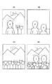
図42は、図41のステップ(G−3、G−4)において画像の領域選択する具体的な一例を示す図であり、(a)は画像全体を示す図、(b)は選択された領域のみを抽出して示す図である。
【0453】
本実施例では、図42(a)に示すように入力画像をディスプレイ上にプレビュー表示し、評価したい領域を矩形で指定するようにした。領域の指定はユーザー自身が判断して選ぶことができるようにするのが望ましい。選択領域の数は複数個指定することができ、当然のことながら画像全領域を選択することも可能である。
【0454】
そして、図42(b)に示すように、選択された複数個の画像は、その縦横比を比較し、必要があれば90°回転処理を施して、自動的に並べ替えられ、出力面積が最も小さくなるように処理を施される。また、記録用紙上にどのように画像が並べられているかをディスプレイ上にイメージ表示するようにした。
【0455】
図42(b)のような形でディスプレイ上に表示される評価画像は、操作性向上のため、画像形成装置から出力される画像を画像処理パラメータからエミュレートした画像とし、画像形成装置から出力されるであろう画像に近い形で表示するようにした。
【0456】
図41の説明に戻り、次に、最良と思われる画像処理パラメータを設定する(G−5、G−7)。この画像処理パラメータは、画像入力装置や画像形成装置などに依存し限定されるものではなく、入力画像を出力するために用いられるすべての画像処理に関するパラメータである。ここで、ステップ(G−5)までで作成した図42(b)に示したような選択領域を並べ替えた画像と、その画像に施した画像処理パラメータとを関連付けてデータベース化(G−6)しておくのが好ましい。
【0457】
画像処理パラメータとしては、カラーバランス、濃度、コントラスト、彩度、シャープネス、特定色(たとえばR、G、B、C、M、Y、K、W(白)、Br(茶))のカラー調整等における各種パラメータが挙げられる。ユーザーはディスプレイ画面を見ながら画像処理パラメータを変更し、最良と思われる画像処理パラメータを選択する。この選択が完了したならば(G−7)ステップ(G−6)のデータベース化を行うようにするとよい。このデータベースには、たとえば、入力画像の名称、データベース化した日時、画像処理パラメータ、評価用に画像出力をしたか否かを示す評価画像出力フラグ、画像全領域を実際に出力(いわゆる本番出力)したか否かを示す本番出力フラグが、評価用画像と対応付けられて記憶される。これによって、本番出力時に、ユーザーが新たに画像処理パラメータを設定しなおす必要がなくなる。また、後日同一の画像を出力したい場合、本番出力フラグを調べて出力済みであれば、評価画像出力をせずに本番出力が可能である。
【0458】
なお、上記の例では領域選択をしてから画像処理パラメータを調整するようにしたが、本発明はこれに限られるものではなく、画像全体を見て画像処理パラメータを調整し、その後に領域選択を行うようにしてもよい。
【0459】
図41の説明に戻り、次に、別のオリジナル画像についても評価画像を作成するか否かをユーザーに尋ねる(G−8)。別のオリジナル画像について評価画像を作成せず、画像処理パラメータの再調整が不要の場合には(G−9)、評価画像を生成する(G−10)。
【0460】
ステップ(G−10)では、先に選択した領域の画像を画像形成装置に送信する画像データに変換する。この処理は領域選択の後で画像出力前であればいつ行ってもよい。さらにステップ(G−10)では、先に調整して決定した画像処理パラメータ等の、データベースで画像に関連付けられて保存された関連情報を画像化し画像形成装置に送信する画像データに変換する。この関連情報は文字コードで画像形成装置に対して送信するようにしてもよい。この処理は画像処理パラメータ決定の後で画像出力前であればいつ行ってもよい。
【0461】
次に、ステップ(G−11)では、画像形成装置(図1に示したLEDプリンタ2)に対して評価画像や関連情報の画像データを送信し、画像出力を行う。画像出力結果の一例を図43に示す。
【0462】
図43は、本発明の第18の実施例において画像形成装置から出力されるプリント評価画像の一例を示す図である。
【0463】
図43は、1つのオリジナル画像について、画像処理パラメータを変えた4種類の評価画像を作成し、1枚の記録用紙にプリントした例である。図43のAはステップ(G−3)で選択された画像領域に対し、ステップ(G−5)で指定された画像処理パラメータで画像処理を施した画像である。また、図43のBは、図43のAのデータベースを文字の画像データにしたものであり、図43のAに対するものであることが分かるように、図43のAの下に配置してある。
【0464】
ユーザーは出力された評価画像を目視で評価し(G−12)、たとえば図43のように複数プリントされた評価画像の中から最良の画像を選択し、本番出力する画像を決定する(G−13)。
【0465】
ユーザーは、ステップ(G−13)で選択した評価画像で用いられた画像処理パラメータを採用し本番出力を実行する(G−14)。
【0466】
ここで、図43とは別の評価画像のプリント例について説明する。
【0467】
図44は、複数のオリジナル画像のそれぞれにおける選択領域を示す図であり、(a)〜(d)はそれぞれ別のオリジナル画像を示す図である。
【0468】
図45は、図44(a)〜(d)に示した選択領域を1枚の記録用紙に画像形成した評価画像の一例を示す図である。
【0469】
ここで、図44(a)〜(d)に示すように、図44(a)のオリジナル画像では領域A、領域Bおよび領域Cが選択され、図44(b)のオリジナル画像では領域Dおよび領域Eが選択され、図44(c)のオリジナル画像では領域Fおよび領域Gが選択され、図44(d)のオリジナル画像では領域H、領域I、領域Jおよび領域Kが選択されたものとする。
【0470】
この場合、本実施例によれば、図45に示すように、それぞれのオリジナル画像の選択領域の画像およびその画像の画像処理パラメータ等の情報を、1枚の記録用紙上に画像形成することもできる。このようにすれば、さらに省資源化が実現できる。
【0471】
なお、本実施例では、図1で示したホストコンピュータ1側で領域選択した画像データと、画像処理パラメータの画像データを作成した。ホストコンピュータ1からLEDプリンタ2へ前述の画像データと画像処理パラメータ、画像を送る。LEDプリンタ2において画像処理パラメータで画像データを画像処理し、評価画像とした。本発明において評価画像をホストコンピュータ1とLEDプリンタ2のどちらが作成するか、あるいは両方で作成するかは限定されない。ホストコンピュータ1で領域選択した画像データの作成と画像処理パラメータによる画像処理を行った評価画像の作成を行うようにしてもよい。あるいは、LEDプリンタ2に画像を表示する表示部を設け、LEDプリンタ2側で評価画像を作成するようにしてもかまわない。
【0472】
次に、本発明の第19の実施例について説明する。
【0473】
本実施例は、たとえば画像の拡大や縮小等の複数の画素の情報に基づいて行う画像処理において、ブロック処理を行い、より少ないメモリ容量で実行可能とし、割り込みが容易に作成できるルーチンを提供することを目的とする。
【0474】
画像の拡大縮小方法は、バイリニア(双1次補間)の場合は周囲4点の画素データから、バイキュービック(双3次補間)の場合は周囲16点の画素データから、拡大縮小後の画素データを作成する。
【0475】
通常、画素データは一旦、元画像用に全画素データをメモリ上に展開し、処理後の画像用のメモリを拡大縮小率に合わせて用意し、各画素について順々に演算を行っていく。
【0476】
しかし、このような方法であると、大量のメモリが必要となってしまうし、また、処理を開始した場合、途中で他の処理を実行するための割り込みを実施するためには特別な操作が必要となる。
【0477】
これを解決するため、本実施例では、拡大・縮小処理を行う領域をブロック化し、処理を実行するようにした。また、拡大縮小など複数の画素を用いて行う画像処理の場合、各ブロック化された境界での演算があるため、境界の画像データを内部バッファメモリに保存し、このバッファの情報をブロック間をまたがる処理に用いることによって、ブロック境界のない画像を得ることができる。また、画像データをブロックごとに用意し、画像処理を行う際に、用意する各ブロックに同じ画素データをダブらせて用意する必要はない。
【0478】
なお、本実施例の画像処理は、図1に示したホストコンピュータ1側で実行されてもよいし、LEDプリンタ2側で実行されてもかまわない。
【0479】
図46は、本発明の第19の実施例を実施する構成のブロック図である。
【0480】
図46において、ROM135は実行する画像処理のプログラムが格納されている不揮発メモリであり、CPU136はROM135に格納されたプログラムを実行し、データ処理、I/F137、RAM138およびROM135の制御を行うものであり、I/F137は外部との画像データや制御信号のやり取りを行うインタフェースであり、RAM138は境界領域用メモリであって画像データ用ブロックメモリなどのランダムアクセスメモリである。
【0481】
RAM138は、CPU136によって管理され、ブロック化された画像データを記憶する画像データブロック138bの領域と、ブロック化された画像データの境界領域のデータを記憶する境界領域用バッファメモリ部138aと、画像処理後の画像データを保存する領域とを有する。
【0482】
I/F137は、ブロック化画像処理を行うための外部とのインタフェースである。図46では制御信号用および画像データ用の2つのバスに分かれているが、制御信号と画像データとは同一のバス上を転送するようにしてもかまわない。制御信号としては、本実施例では、原画像サイズ、処理後画像サイズ、原画像の保存場所、終了フラグ等の、画像の情報や処理の状況などがやり取りされる。
【0483】
図47は、本発明の第19の実施例における処理のフローチャートを示す図である。
【0484】
また、図48は、本発明の第19の実施例における処理を説明する図である。
【0485】
まず、ステップ(H−1)では初期化処理を行う。ここでは、原画像サイズ、処理後画像サイズ、画像処理種別、ブロックサイズの指定などの画像処理に必要な基本情報を指定する。本実施例ではこれらの情報を以下のように決定して用いる。
(1)ブロックサイズ
本実施例においてブロックサイズは処理後画像用のブロックの大きさを指定し、このブロックサイズから原画像データ用のブロックサイズを決定した。また、これとは逆に、原画像データ用のブロックサイズを指定し、処理後画像データ用のブロックサイズを決定するようにしてもよい。さらに、原画像データ用に用意できる最大のブロックサイズと処理後画像データ用に用意できる最大のブロックサイズを指定し、原画像サイズと処理後画像サイズで計算される拡大率から、実際に使用する原画像用のブロックサイズおよび処理後画像用ブロックサイズを決定してもよい。
(2)原画像サイズ
境界領域用バッファメモリ部138aのサイズおよび拡大率の計算に使用した。
(3)処理後画像サイズ
原画像データ用のブロックサイズおよび拡大率を決定するのに使用した。
(4)画像処理種別
図47のステップ(H−6)において、バイリニア、バイキュービックの選択に使用する。さらに、境界領域用バッファメモリ部138aのサイズを計算するのに使用する。
【0486】
次に、図47のステップ(H−2)では、境界領域用バッファメモリ部138aを確保する。確保するサイズは画像処理の種別によって異なる。本実施例では、バイリニアの場合には画素1ライン分、バイキュービックの場合には画素2ライン分のバッファを確保するようにした。
【0487】
次に、ブロックに関する情報を設定する(H−3)。本実施例では、原画像ブロックの読み込みアドレス、保存アドレスを設定し、処理を開始する。現在のブロックの処理の完了を確認後、次のブロックの処理を開始させる。
【0488】
ステップ(H−4)では、処理の終了を判定し、最後まで処理が終了していればステップ(H−11)へと進んで終了処理を行い、境界領域用バッファメモリ部138aを開放する。ステップ(H−4)において、処理が終了していればステップ(H−5)へと進む。
【0489】
ステップ(H−5)では、原画像のブロック単位での読み込みを行う。本実施例では処理すべき原画像のあるメモリアドレスから画像情報を読み込んだ。
【0490】
次に、ステップ(H−6)では、画像種別によって実際に行う画像処理を決定する。バイリニアとバイキュービックとのように、画像処理演算がまったく異なる方式であっても、上位からのユーザーインタフェースはまったく同じにすることが可能である。また、本実施例によれば、バイリニアとバイキュービックとを別のルーチンに分割した場合のようにソースコードが大きくなり、プログラムサイズが大きくなってしまうのを回避することができる。
【0491】
ステップ(H−7)、(H−8)では、バイリニアとバイキュービックとのように、それぞれ異なった画像処理を施す。図48に示すように、ブロックの境界の処理では、前のブロックの画像処理において読み込まれた原画像データが次のブロックの画像処理において必要となる。このような場合にも、ステップ(H−5)では前回読み込まれた原画像データは、今回は読み込まれない。このような次のブロックの画像処理において必要となる画像データは、前回のブロックの処理のステップ(H−10)において境界領域用バッファメモリ部138aに保存されている。よって、今回の画像処理で必要だがステップ(H−5)で読み込まれない画像データに関しては、境界領域用バッファメモリ部138aを参照して補い、画像処理を実行する。なお、図48に示すように、最初のブロックの画像処理においては、処理に必要ないので、境界領域用バッファメモリ部138aを使用しない。
【0492】
続いて、画像処理の結果を処理後画像へ書きこみを行い(H−9)、境界領域用バッファメモリ部138aに、ステップ(H−5)で読み込まれた画像データのブロック境界部分をコピーする(H−10)。
【0493】
以上の処理によって、本実施例では、たとえば画像の拡大や縮小等の複数の画素の情報に基づいて行う画像処理において、ブロック処理を行い、より少ないメモリ容量で実行可能とし、割り込みが容易に作成できるルーチンを提供することができる。
【0494】
次に、本発明の第20の実施例について説明する。
【0495】
本実施例は、第19の実施例と同様に、たとえば画像の拡大や縮小等の複数の画素の情報に基づいて行う画像処理において、ブロック処理を行い、より少ないメモリ容量で実行可能とし、割り込みが容易に作成できるルーチンを提供することを目的とするものである。
【0496】
図49は、本発明の第20の実施例における処理のフローチャートを示す図である。
【0497】
この第20の実施例が第19の実施例と異なる点は、画像処理種別がなく、実行する画像処理が1つに限定されている点である。従って、図49のステップ(I−1)の初期化処理においては画像処理種別がなく、ステップ(I−5)の後にすぐにステップ(I−6)の画像処理が実行される。他の点において、この第20の実施例は、先に説明した第19の実施例と同様であるので、詳しい説明は省略する。
【0498】
【発明の効果】
以上説明したように、本発明によれば、LEDプリンタ等の画像形成装置の総合的な改善を行うことができる。
【図面の簡単な説明】
【図1】本発明の一実施の形態によるLEDプリンタの制御系の構成を示すブロック図である。
【図2】図1に示したLEDアレイ基板上に配置されるLEDの配列を示す図である。
【図3】図1に示したLEDプリンタの第1の実施例の構成を示すブロック図である。
【図4】図3に示した本発明の第1の実施例の制御系の構成を示すブロック図である。
【図5】本発明の第2の実施例の制御系の構成を示すブロック図である。
【図6】本発明の第3の実施例の制御系の構成を示すブロック図である。
【図7】本発明の第4の実施例の制御系の構成を示すブロック図である。
【図8】本発明の第5の実施例の制御系の構成を示すブロック図である。
【図9】本発明の第6の実施例の制御系の構成を示すブロック図である。
【図10】本発明の第7の実施例の制御系の構成を示すブロック図である。
【図11】省電力が可能なLEDプリンタの第1の応用例の制御を示す状態遷移図である。
【図12】省電力が可能なLEDプリンタの第2の応用例の制御を示す状態遷移図である。
【図13】本発明の第8の実施例の制御系の構成を示すブロック図である。
【図14】本発明の第9の実施例の制御系の構成を示すブロック図である。
【図15】本発明の第10の実施例の制御系の構成を示すブロック図である。
【図16】本発明の第10の実施例で用いるテストチャートの一例を示す図である。
【図17】画像データと変換テーブルの出力値との関係すなわち補正カーブと、変換テーブルの出力値と測定された濃度との関係とを示す図である。
【図18】本発明の第11の実施例の制御系の構成を示すブロック図である。
【図19】本発明の第11の実施例のMCH補正で用いるテストチャートの一例を示す図である。
【図20】従来のテストチャートの一例を示す図である。
【図21】各色のチャートを濃度の低いほうから高いほうへ5段分並べて示す図であり、目標濃度が存在する範囲を説明する図である。
【図22】画像データと変換テーブルの出力値との関係すなわち補正カーブと、変換テーブルの出力値と測定された濃度との関係とを示す図である。
【図23】画像データと変換テーブルの出力値との関係すなわち補正カーブと、変換テーブルの出力値と測定された濃度との関係とを示す図である。
【図24】本発明の第12の実施例における処理のフローチャートを示す図である。
【図25】本発明の第12の実施例において用いる現像液劣化判定用チャートを示す図である。
【図26】本発明の第13の実施例における処理のフローチャートを示す図である。
【図27】本発明の第14の実施例の構成を示すブロック図である。
【図28】本発明の第15の実施例の構成を示すブロック図である。
【図29】従来のユーザーチャネルにおいて、入力された画像データのレベルと出力する画像データのレベルとの関係を示す図である。
【図30】本発明の第16の実施例の制御系の構成を示すブロック図である。
【図31】本発明の第16の実施例で用いるテストチャートの一例を示す図である。
【図32】ユーザー操作パラメータについて一覧に示す表図である。
【図33】UCH用LUTの一例を示す図である。
【図34】本発明の第16の実施例における重みwの一例を示す図である。
【図35】本発明の第16の実施例における重みwの例であって、図34とは別の例を示す図である。
【図36】本発明の第16の実施例における、ユーザー操作パラメータと重みとの関係について説明する図である。
【図37】図32に示したユーザー操作パラメータが指定された場合の、シアンについての変換特性の一例を示す図である。
【図38】本発明の第17の実施例の制御系の構成を示すブロック図である。
【図39】本発明の第17の実施例で用いるテストチャートの一例を示す図である。
【図40】本発明の第17の実施例において、9×9×9点の補正済みUCH用LUTを求める際、5×5×5点のUCH用テストチャートに存在しない点の位置を説明する図である。
【図41】本発明の第18の実施例の処理のフローチャートを示す図である。
【図42】図41のステップ(G−3、G−4)において画像の領域選択する具体的な一例を示す図であり、(a)は画像全体を示す図、(b)は選択された領域のみを抽出して示す図である。
【図43】本発明の第18の実施例において画像形成装置から出力されるプリント評価画像の一例を示す図である。
【図44】複数のオリジナル画像のそれぞれにおける選択領域を示す図であり、(a)〜(d)はそれぞれ別のオリジナル画像を示す図である。
【図45】図44(a)〜(d)に示した選択領域を1枚の記録用紙に画像形成した評価画像の一例を示す図である。
【図46】本発明の第19の実施例を実施する構成のブロック図である。
【図47】本発明の第19の実施例における処理のフローチャートを示す図である。
【図48】本発明の第19の実施例における処理を説明する図である。
【図49】本発明の第20の実施例における処理のフローチャートを示す図である。
【符号の説明】
1 ホストコンピュータ
2 LEDプリンタ
3 IPB
4 SCSIインタフェース
5 画像メモリ
6 CPU
7 空間フィルタ
8 色変換部
9 メモリ
10 MCB
11 CPU
12 クロックジェネレータ
13 CSB
14、15、16 ステッピングモーター
17 DCモーター
18、19、20 ソレノイド
21 OPB
22 LCD
23 濃度計
26a、26b、26c LBB
27a、27b、27c エレメント配列補正部
28a、28b、28c LUT部
29a、29b、29c PWM部
30a、30b、30c、30d、30e LDB
31a、31b、31c、31d、31e 定電流ドライバ
32a、32b、32c LEDアレイ基板
33a、33b、33c サーミスタ
34a、34b、34c ヒーター
35a、35b、35c ファン
36 回転ドラム
37 主走査DCモーター
38 エンコーダ
39a、39b、39c PAB
154 現像機
155 PMB
156 CPU
157 メモリ
158 ヒーター
159 ファン
160 ポンプ
161 センサ
162 搬送モーター
163 シャッタ
164 Jユニット[0001]
BACKGROUND OF THE INVENTION
The present invention relates to an image forming apparatus, and more particularly, to an image forming apparatus that forms an image by exposing, for example, silver salt photosensitive paper based on digital image data.
[0002]
[Prior art]
2. Description of the Related Art Conventionally, an image forming apparatus such as a digital printer that forms an image based on digital image data is well known. This image forming apparatus is used not only as a so-called printer, but also as an image forming unit such as a copying machine or a facsimile machine.
[0003]
For such an image forming apparatus, various systems such as a laser system, an electrophotographic system, a thermal system, and an ink jet system are used, and image forming apparatuses employing these systems are widely supplied to the market.
[0004]
Among these, in image forming apparatuses that use ink, fine particle toner, etc. for image formation, although improvement in image quality such as sharpness and gradation is recognized, it is possible to make finer images. At present, there is a problem in the degree of color development, color developability, and the like, and there is a difference in image quality compared with a photographic image using a silver halide (silver salt) photographic light-sensitive material.
[0005]
In recent years, a silver salt photosensitive paper is used as a recording paper, and an LED (light emitting diode) that emits, for example, three primary colors of B (blue), G (green), and R (red) as a light source when the recording paper is exposed. An LED printer using the above has been proposed. According to this LED printer, an image having a quality close to that of a silver salt photograph image can be obtained, and has recently been in the spotlight.
[0006]
Further, the LED used as the light source for exposure in this LED printer can bring its emission wavelength close to the sensitivity range of conventional silver exposure photosensitive paper for analog exposure. There is an advantage that the photosensitive paper can be used as it is.
[0007]
[Problems to be solved by the invention]
However, although the LEDs used for exposure in the above-described LED printer have the advantages described above, in actual use, the conditions and accuracy of the light emission intensity, light emission distribution, etc. are appropriate in order to give appropriate exposure to the photosensitive paper. There must be, and the adjustment is complicated.
[0008]
That is, in an LED printer, a unit is generally configured by providing a plurality of LEDs for each color of B, G, and R, and an LED exposure head is configured by this unit. For this reason, when this LED exposure head is used, it is affected by luminance variations caused by variations in characteristics of individual LEDs in each unit, arrangement errors in the arrangement of a plurality of LEDs, etc. The light emission distribution etc. will fluctuate.
[0009]
Furthermore, since variations occur due to differences in LED characteristics themselves among the B, G, and R units, various inspections and adjustments of the units are indispensable for improving the quality of the print finish.
[0010]
Even if light emission for exposure can be properly performed, variations in photosensitive characteristics due to differences in the types of photosensitive paper and manufacturing lots, or deterioration of the developer when developing exposed photosensitive paper The influence of the state, developer temperature, development time, drying time, and the like, as well as the influence of environmental temperature, humidity, etc., are intricately related to the print quality.
[0011]
For this reason, it is necessary to make efforts to control the device in consideration of the above-mentioned various effects. However, not all combinations can be performed automatically, and test printing is performed after setting predetermined conditions before printing. It is the current situation that the user repeats changing the setting conditions by executing the results, and when trying to obtain a higher quality print result, complicated condition setting according to the test print result before starting printing In order for the user to set the conditions, not only knowledge about the operation method of the image forming apparatus but also high knowledge about characteristics of the photosensitive paper, development conditions, and the like is required.
[0012]
Furthermore, in order to provide a higher quality image that the user will be satisfied with, not only will the original image be reproduced very faithfully, but in some cases it may be modified by the user request, for example, partial color or density of the image, Even when the gradation is changed, the original image is enlarged or reduced, or the layout is changed by a plurality of images, the quality of the image of the entire print must be made high. However, in such a case, even if you try to set print conditions that take into account the print variations due to the above-mentioned various variations and differences in various conditions, the chart used for test printing is basically the color, density, gradation, etc. In the case of charts with different settings, it is not possible to judge because the chart does not correspond to the finished state of the actual changed part even if you look at the test print result, and print the image you want to print once under the conditions set as a result. Therefore, it was necessary to make a judgment by looking at the result, and until a satisfactory result was obtained, repeated wasteful printing was performed.
[0013]
For this reason, the image forming apparatus itself can be made a high-precision mechanism capable of realizing control corresponding to various image processing technologies, the memory configuration and the processing procedure can be improved to facilitate the operation of the image forming apparatus itself, and the test. The various charts used at the time of printing do not require a high level of knowledge, so that various conditions can be easily set and checked. Comprehensive improvements such as improvement so that the finish can be seen at a glance are desired.
[0014]
The present invention has been made in view of the above points, and an object thereof is to provide an image forming apparatus that comprehensively improves the above-described problems.
[0015]
[Means for Solving the Problems]
In order to achieve the above object, the present inventionA recording paper cutting means for cutting a long recording paper in a size designated by an external size instruction means, an image recording means for recording an image on the recording paper cut by the recording paper cutting means, and the recording A paper feed unit that transports the recording paper cut by the paper cutting unit to a position where the image recording unit records an image; and a paper discharge unit that discharges the recording paper at the position where the image recording unit records the image to the outside. In the image forming apparatus having the paper unit, the image recording stop instruction unit cancels the image recording after the recording paper is cut by the recording paper cutting unit and before the image recording is performed by the image recording unit. Is instructed, the cut recording paper is temporarily held inside, and the size instructed by the size instructing means is temporarily held in the next image recording. Based on the size relationship with the size of the cut recording paper, the image at the time of the next image recording is recorded on the temporarily held cutting recording paper, or the temporarily held cutting completed Control means for determining whether to record an image at the time of the next image recording on the recording paper that is discharged and newly cut is provided.
[0038]
The present invention also provides:Claim 1In the image forming apparatus described in the above, at the time of the next image recording, thesizeInstructed by the instruction meanssizeOf the cut recording paper temporarily heldsizeThe image at the time of the next image recording is recorded on the cut recording paper that is temporarily held only when the two match.
[0039]
The present invention also provides:Claim 1In the image forming apparatus described in the above, at the time of the next image recording, thesizeInstructed by the instruction meanssizeOf the cut recording paper temporarily heldsizeIn the following cases, the image at the time of the next image recording is recorded on the cut recording paper temporarily held.
[0040]
The present invention also provides:Claim 1In the image forming apparatus described in the above, at the time of the next image recording, thesizeInstructed by the instruction meanssizeOf the cut recording paper temporarily heldsizeIn the following cases, the temporarily held cut recording paper is used for the next image recording.sizeInstructed by the instruction meanssizeThen, the image at the time of the next image recording is recorded on the cut recording paper temporarily held.
[0041]
The present invention also provides:Claim 1In the image forming apparatus described in the above, at the time of the next image recording, thesizeInstructed by the instruction meanssizeAnd said temporary holdRecording paper sizeIs recorded on the cut recording paper that is temporarily held, or the image at the next image recording is recorded, or at the time of the next image recordingsizeInstructed by the instruction meanssizeOf the cut recording paper temporarily heldsizeIn the following cases, the user can select whether to record an image at the time of the next image recording on the temporarily cut cut recording paper.
[0042]
The present invention also provides a recording paper cutting method based on image data input from an external image data input means.sizeDetermine the recording paper cuttingsizeDetermining means and cutting of the recording papersizeDetermined by means of determinationsizeA recording paper cutting means for cutting a long recording paper, an image recording means for recording an image on the recording paper cut by the recording paper cutting means, and a recording paper cut by the recording paper cutting means. An image forming apparatus comprising: a paper feed unit that conveys to a position where an image is recorded by the image recording unit; and a paper discharge unit that discharges the recording paper at a position where the image is recorded by the image recording unit If the image recording stop instruction is instructed by the image recording stop instruction means after the recording paper cutting by the recording paper cutting means and before the image recording by the image recording means, the cutting is performed. The recorded paper is temporarily held inside and the recording paper is cut when the next image is recorded.sizeDecision means decidedsizeOf the cut recording paper temporarily heldsizeThe image at the time of the next image recording is recorded on the temporarily held cut recording paper, or the temporarily held cut recording paper is discharged and newly stored. Control means for determining whether to record an image at the time of the next image recording on the recording paper to be cut.
[0043]
The present invention also provides:Claim 6In the image forming apparatus, the recording paper is cut at the next image recording time.sizeDecision means decidedsizeOf the cut recording paper temporarily heldsizeThe image at the time of the next image recording is recorded on the cut recording paper that is temporarily held only when the two match.
[0044]
The present invention also provides:Claim 6In the image forming apparatus, the recording paper is cut at the next image recording time.sizeDecision means decidedsizeOf the cut recording paper temporarily heldsizeIn the following cases, the image at the time of the next image recording is recorded on the cut recording paper temporarily held.
[0045]
The present invention also provides:Claim 6In the image forming apparatus, the recording paper is cut at the next image recording time.sizeDecision means decidedsizeOf the cut recording paper temporarily heldsizeIn the following cases, the cut recording paper temporarily held is cut off at the time of the next image recording.sizeDecision means decidedsizeAfter cutting according to the above, an image at the time of the next image recording is recorded on the cut recording paper temporarily held.
[0046]
The present invention also provides:Claim 6In the image forming apparatus, the recording paper is cut at the next image recording time.sizeDecision means decidedsizeAnd said temporary holdRecording paperofsizeIs recorded on the cut recording paper that has been temporarily held, or the recording paper is cut at the time of the next image recording.sizeDecision means decidedsizeOf the cut recording paper temporarily heldsizeIn the following cases, the user can select whether to record an image at the time of the next image recording on the temporarily cut cut recording paper.
[0047]
The present invention also provides:Claim 1 to 10In the image forming apparatus according to any one of the above, the next image recording is performed even if a predetermined time elapses after the image recording stop instruction unit instructs the image recording stop and the cut recording paper is temporarily held inside. When there is no instruction, the temporarily held cut recording paper is forcibly discharged.
[0048]
The present invention also provides:Claim 11In the image forming apparatus described above, the user can set a predetermined time from when the cut recording paper is temporarily held inside until the recording paper is forcibly discharged.
[0057]
DETAILED DESCRIPTION OF THE INVENTION
Hereinafter, embodiments of the present invention will be described with reference to the drawings.
[0058]
Here, an example of an image forming apparatus will be described with reference to an LED printer that exposes silver halide photosensitive paper by an LED exposure head based on image data sent from a host computer and then develops it to obtain a print result.
[0059]
FIG. 1 is a block diagram showing a configuration of a control system of an LED printer according to an embodiment of the present invention.
[0060]
The basic operation of the LED printer shown in FIG. 1 will be described below.
[0061]
First, the user selects an image to be printed on the
[0062]
The
[0063]
When the transfer of the image data and the print conditions is completed, the
[0064]
At that time (or prior to these processes), the MCB-
[0065]
The IPB-
[0066]
Here, the photosensitive paper accommodated in the
[0067]
Further, when print condition parameters are designated from the
[0068]
When the start of the print sequence is notified from the IPB-
[0069]
The MCB-
[0070]
Thereafter, while the drum rotating stepping
[0071]
Thereafter, the
[0072]
The rotational speed of the
[0073]
The
[0074]
The IPB-
[0075]
The
[0076]
The MCB-
[0077]
FIG. 2 is a diagram showing an array of LEDs arranged on the
[0078]
Although FIG. 2 shows the
[0079]
In the element arrangement correction of the
[0080]
By the way, since the light quantity and emission wavelength of the LED change under the influence of temperature, a signal from the
[0081]
The IPB-
[0082]
When the
[0083]
If the
[0084]
Thereafter, the MCB-
[0085]
When the CPU (hereinafter referred to as “PMB-CPU”) 156 of the developing device control board (hereinafter referred to as “PMB”) 156 detects the exposed photosensitive paper by the
[0086]
Next, the above-described LED light amount calibration will be described.
[0087]
Since the light quantity of the LED decreases with time, it is necessary to always correct the light quantity to a predetermined light quantity by the LED light quantity calibration process.
[0088]
When the power of the
[0089]
Upon receiving this instruction, the MCB-
[0090]
When the IPB-
[0091]
Upon receiving this photometry command, the MCB-CPU 11 A / D converts photometric signals from the photosensor amplifier boards (hereinafter referred to as “PAB”) 39a, 39b, and 39c for each color of B, R, and G, and the IPB-
[0092]
The IPB-
[0093]
Next, correction other than LED light quantity calibration will be described.
[0094]
Factors that cause fluctuations in the image of the print result that is formed and output by the
[0095]
Therefore, in the present embodiment, each factor requiring correction at the time of image formation is called a channel, and different correction is performed for each channel. In this way, when the factor occurs, it is sufficient to recalculate the correction amount only for the channel corresponding to the factor, and the number of times the correction amount is recalculated while operating the
[0096]
In the
[0097]
First, master channel correction will be described.
[0098]
In principle, it is desirable to perform the master channel correction once a day before starting the printing operation by the
[0099]
The operator operates the operation panel 21 of the
[0100]
When the MCH test chart is discharged from the
[0101]
The IPB-
[0102]
Note that the IPB-
[0103]
Next, paper channel correction will be described.
[0104]
In principle, the paper channel correction may be performed when new photosensitive paper is used. That is, when the first photosensitive paper that has been subjected to paper channel correction in the past is once removed and printed with a different photosensitive paper, the first photosensitive paper is used again. Printing may be performed with the correction amount obtained when paper channel correction has been performed in the past on photosensitive paper.
[0105]
The operator operates the operation panel 21 of the
[0106]
When the PCH test chart is ejected from the
[0107]
The IPB-
[0108]
Note that the IPB-
[0109]
The
[0110]
Next, a first embodiment of the present invention will be described.
[0111]
The photosensitive paper used for printing by the
[0112]
Therefore, in the first embodiment, the printing result is stabilized by keeping the temperature inside the
[0113]
FIG. 3 is a block diagram showing the configuration of the first embodiment of the
[0114]
The
[0115]
FIG. 4 is a block diagram showing the configuration of the control system of the first embodiment of the present invention shown in FIG.
[0116]
In the developing
[0117]
The
[0118]
In this embodiment, the temperature in the
[0119]
Next, a second embodiment of the present invention will be described.
[0120]
FIG. 5 is a block diagram showing the configuration of the control system of the second embodiment of the present invention.
[0121]
In the second embodiment, the temperature of the exposed portion is not adjusted, and even if there is a temperature change in the exposed portion, the print result is not changed.
[0122]
Image data from the
[0123]
According to the present embodiment, the exposure amount on the photosensitive paper can be varied according to the temperature of the exposed portion by doing in this way, so that the print result does not fluctuate due to the temperature of the exposed portion. can do.
[0124]
For example, the image
[0125]
Next, a third embodiment of the present invention will be described.
[0126]
FIG. 6 is a block diagram showing the configuration of the control system of the third embodiment of the present invention.
[0127]
Similarly to the second embodiment, the third embodiment also attempts to eliminate fluctuations in the print result even if there is a temperature change in the exposure section without adjusting the temperature of the exposure section.
[0128]
Image data from the
[0129]
According to the present embodiment, the exposure amount on the photosensitive paper can be varied according to the temperature of the exposed portion by doing in this way, so that the print result does not fluctuate due to the temperature of the exposed portion. can do.
[0130]
For example, the data conversion means 62 is the
[0131]
Next, a fourth embodiment of the present invention will be described.
[0132]
In the fourth embodiment, the power consumption of the LED printer is reduced and the progress of the deterioration of the developer is suppressed.
[0133]
A developing solution used for development in an image forming apparatus having an exposure and development process changes in development characteristics depending on the temperature. Therefore, in such an image forming apparatus, the developer is warmed and development is performed at a predetermined temperature. The temperature of the developer that can be developed is relatively high, and power consumption by a heater or the like provided for warming the developer is large, and it is desired to reduce it. Further, the higher the temperature of the developer, the faster the deterioration proceeds.
[0134]
Therefore, in this embodiment, the heater for heating the developer and the circulation pump for circulating the solution so that the temperature of the developer does not vary depending on the location are reduced, and the developer is deteriorated. The purpose is to suppress progress.
[0135]
FIG. 7 is a block diagram showing the configuration of the control system of the fourth embodiment of the present invention.
[0136]
In the fourth embodiment, the unprocessed detection means 65 for detecting that the development process has not been performed for a predetermined time and the temperature of the developer are switched based on the time lapse signal of the detection result by the unprocessed detection means 65. Developer temperature switching means 66 for outputting a temperature switching signal of the developer, and developer temperature control means 67, 68 for switching the developer temperature based on the temperature switching signal from the developer temperature switching means 66, and a
[0137]
In FIG. 7, only two
[0138]
Next, the operation of the fourth embodiment will be described.
[0139]
In the LED printer of this embodiment, the temperature of the developer is normally maintained at a first predetermined temperature at which development processing can be performed.
[0140]
The unprocessed detection means 65 monitors whether the exposed photosensitive paper is conveyed to the developing unit and the development process is executed. If the development process is not performed for a predetermined time, the unprocessed detection means 65 is notified by a time lapse signal. Output.
[0141]
The developer temperature switching means 66, to which a time lapse signal indicating that the development processing has not been performed for a predetermined time, is input, outputs a temperature switching signal to the developer temperature control means 67, 68, thereby switching the temperature. Instruct.
[0142]
In the developer temperature control means 67 and 68 to which the temperature switching signal is inputted, the temperature of the developer in the
[0143]
According to the present embodiment, for example, when the LED printer is not used for a long time, the temperature of the developer is set to the second predetermined temperature lower than the first predetermined temperature at which the development process can be performed, so that the consumption occurs. Electric power can be reduced. If the second predetermined temperature is set higher than room temperature, the temperature of the developing solution returns to room temperature faster than when the LED printer is turned off. There is also an effect that the development process can be executed. Furthermore, there is also an effect of suppressing the progress of the deterioration of the developing solution by lowering the temperature of the developing solution when not developing.
[0144]
Next, a fifth embodiment of the present invention will be described.
[0145]
The fifth embodiment is also intended to reduce the power consumption of the LED printer and suppress the progress of deterioration of the developer. This fifth embodiment is a drying tank in addition to the control of the fourth embodiment. It is intended to realize further reduction in power consumption by controlling the temperature of the liquid crystal.
[0146]
FIG. 8 is a block diagram showing the configuration of the control system of the fifth embodiment of the present invention.
[0147]
In the fifth embodiment shown in FIG. 8, the same components as those in the fourth embodiment shown in FIG. 7 are denoted by the same reference numerals, and detailed description thereof is omitted.
[0148]
In the fifth embodiment, in addition to the configuration of the fourth embodiment, a drying tank that outputs a stop signal for stopping the operation of the drying tank based on the time lapse signal of the detection result by the unprocessed detection means 65 A control stop means 71 and a drying tank temperature control means 72 for stopping the operation of the drying tank based on a stop signal from the drying tank control stop means 71 are provided, and the temperature of the drying
[0149]
Next, the operation of the fifth embodiment will be described.
[0150]
In the LED printer of this embodiment, normally, the temperature in the drying
[0151]
The unprocessed detection means 65 monitors whether the exposed photosensitive paper is conveyed to the developing unit and the development process is executed. If the development process is not performed for a predetermined time, the unprocessed detection means 65 is notified by a time lapse signal. Output.
[0152]
The drying tank control stop means 71 to which the time lapse signal indicating that the development processing has not been performed for a predetermined time is input outputs a stop signal to the drying tank temperature control means 72, thereby stopping the operation of the drying
[0153]
In the drying tank temperature control means 72 to which the stop signal is input, the operation of the heater and the
[0154]
According to the present embodiment, for example, when the LED printer is not used for a long time, there is an effect that it is possible to reduce the electric power for raising the temperature of the drying tank.
[0155]
Next, a sixth embodiment of the present invention will be described.
[0156]
The sixth embodiment is also intended to reduce the power consumption of the LED printer and to suppress the progress of the deterioration of the developer. This sixth embodiment includes a developer solution in addition to the control of the fifth embodiment. The power consumption is further reduced by controlling the heaters and the circulation pumps 69a and 69b to raise the temperature.
[0157]
FIG. 9 is a block diagram showing the configuration of the control system of the sixth embodiment of the present invention.
[0158]
In the sixth embodiment shown in FIG. 9, the same components as those in the fourth embodiment shown in FIG. 7 and the fifth embodiment shown in FIG. .
[0159]
In the sixth embodiment, an unprocessed detection means 76 is provided in place of the unprocessed detection means 65 shown in FIG. 8, and a developer temperature control means is provided instead of the developer temperature control means 67 and 68 shown in FIG. 78 and 79 are provided, and a developer temperature control stop means 77 is further provided.
[0160]
The
[0161]
The developer temperature switching means 66 outputs a temperature switching signal for switching the temperature of the developer based on the first time detection signal detected by the unprocessed detection means 76.
[0162]
The developer temperature
[0163]
The developer temperature control means 78 and 79 switch the developer temperature based on the temperature switching signal from the developer temperature switching means 66 and the temperature rise of the developer based on the stop signal from the developer temperature control stop means 77. Stop operation.
[0164]
Next, the operation of the sixth embodiment will be described.
[0165]
The
[0166]
The developer temperature switching means 66 to which the first time lapse signal indicating that the development processing has not been performed for the first predetermined time is input outputs a temperature switching signal to the developer temperature control means 78 and 79. To instruct the switching of the temperature.
[0167]
In the developer temperature control means 78 and 79 to which the temperature switching signal is input, the temperature of the developer in the
[0168]
Further, the drying tank control stop means 71 to which the first time lapse signal indicating that the development processing has not been performed for the first predetermined time is input outputs a stop signal to the drying tank temperature control means 72. To stop the operation of the drying
[0169]
In the drying tank temperature control means 72 to which the stop signal is input, the operation of the heater and the
[0170]
Further, when the development processing is not performed for a second predetermined time longer than the first predetermined time, the unprocessed detection means 76 outputs that fact by a second time lapse signal.
[0171]
The developer temperature
[0172]
In the developer temperature control means 78 and 79 to which the stop signal is input, the operations of the heater and the circulation pumps 69a and 69b are stopped.
[0173]
According to this embodiment, when the LED printer is not used for a long time, the temperature raising operation of the developer is stopped, so that the power consumption can be further reduced.
[0174]
Next, a seventh embodiment of the present invention will be described.
[0175]
In addition, this seventh embodiment also enables the user to efficiently work using the LED printer while reducing the power consumption of the LED printer and suppressing the progress of deterioration of the developer. In the seventh embodiment, in addition to the control of the sixth embodiment, a timer function is provided for automatically starting the temperature raising operation when a predetermined time comes, and is necessary until the LED printer can be used. It is intended to shorten the time.
[0176]
FIG. 10 is a block diagram showing the configuration of the control system of the seventh embodiment of the present invention.
[0177]
In the seventh embodiment shown in FIG. 10, the same components as those in the sixth embodiment shown in FIG. 9 are denoted by the same reference numerals, and detailed description thereof is omitted.
[0178]
In the seventh embodiment, an unprocessed detection means 80 is provided instead of the unprocessed detection means 76 shown in FIG. 9, and an apparatus activation means 81 is further provided.
[0179]
When the unprocessed detection means 80 detects that the development process has not been performed for the first predetermined time, the unprocessed detection means 80 outputs a first time lapse signal indicating that the development process has not been performed for a first predetermined time, When it is detected that it has not been performed for a long second predetermined time, a second time-lapse signal indicating that is output. When the unprocessed detection unit 80 receives the activation signal from the
[0180]
The device activation means 81 outputs an activation signal when a preset time is reached.
[0181]
Next, the operation of the seventh embodiment will be described.
[0182]
The unprocessed detection unit 80 monitors whether the exposed photosensitive paper is conveyed to the developing unit and the development process is executed, and if the development process is not performed for the first predetermined time, the first time The fact is output by the progress signal.
[0183]
Further, if the development processing is not performed for a second predetermined time longer than the first predetermined time, the unprocessed detection means 80 outputs that fact by a second time lapse signal.
[0184]
The device activation means 81 outputs an activation signal when a preset time is reached.
[0185]
The unprocessed detection unit 80 to which the activation signal from the
[0186]
By this operation, the developer temperature switching means 66 stops outputting the temperature switching signal, and the drying tank control means 71 and the developer temperature
[0187]
In this embodiment, the apparatus activation means 81 is configured to output an activation signal when a preset time is reached, but the temperature raising operation is completed at the preset time. In order to make it ready for development, a start signal may be output before the set time to start the temperature raising operation.
[0188]
Here, an application example of the LED printer capable of power saving shown in the fourth to seventh embodiments will be described with reference to the drawings.
[0189]
FIG. 11 is a state transition diagram showing the control of the first application example of the LED printer capable of saving power.
[0190]
If the power of the LED printer is turned on in the
[0191]
When a predetermined time has elapsed without receiving a print start request in
[0192]
In
[0193]
FIG. 12 is a state transition diagram showing the control of the second application example of the LED printer capable of saving power.
[0194]
If the power of the LED printer is turned on in the
[0195]
When a predetermined time has elapsed without receiving a print start request in
[0196]
In
[0197]
Next, an eighth embodiment of the present invention will be described.
[0198]
In the eighth embodiment, a stable print result can be obtained even when the temperature of the developer is not exactly constant.
[0199]
FIG. 13 is a block diagram showing the configuration of the control system of the eighth embodiment of the present invention.
[0200]
FIG. 13 representatively shows the
[0201]
As described above, the development characteristics of the developer change depending on the temperature. That is, when the temperature of the developer is lower, it is necessary to lengthen the time for immersing the exposed photosensitive paper in the developer. Therefore, in this embodiment, the time for immersing the exposed photosensitive paper in the developing solution is adjusted by varying the conveying speed of the photosensitive paper in the developing unit according to the temperature of the developing solution, and the developing result is made constant.
[0202]
In FIG. 13, the conveyance speed control means 90 outputs speed information for controlling the conveyance speed of the photosensitive paper based on the detection result by the
[0203]
For example, the transport speed control means 90 is the
[0204]
Next, the operation of the eighth embodiment will be described.
[0205]
The conveyance speed control means 90 calculates an optimum photosensitive paper conveyance speed based on the temperature of the developer in the
[0206]
According to this embodiment, since the time for immersing the photosensitive paper in the developer can be changed based on the temperature of the developer, a stable print result can be obtained even in a state where the temperature of the developer is low just after the power is turned on. There is an effect that can be obtained.
[0207]
Next, a ninth embodiment of the present invention will be described.
[0208]
FIG. 14 is a block diagram showing the configuration of the control system of the ninth embodiment of the present invention.
[0209]
FIG. 14 representatively shows the
[0210]
In the ninth embodiment, as in the eighth embodiment described above, a stable print result can be obtained even when the temperature of the developer is not exactly constant. In the eighth embodiment described above, the optimum conveyance speed of the photosensitive paper is calculated by the conveyance speed control means 90. However, in this ninth embodiment, the optimum conveyance speed of the photosensitive paper determined in advance according to the temperature of the developer. Is stored in a non-volatile memory, and the conveyance speed control means 93 reads information from the non-volatile memory to determine and output speed information.
[0211]
In FIG. 14, the
[0212]
For example, the
[0213]
Next, the operation of the ninth embodiment will be described.
[0214]
The conveyance speed control means 93 reads the conveyance speed from the
[0215]
According to this embodiment, since the time for immersing the photosensitive paper in the developer can be changed based on the temperature of the developer, a stable print result can be obtained even in a state where the temperature of the developer is low just after the power is turned on. There is an effect that can be obtained. In addition, since the optimum conveyance speed corresponding to the developer temperature is obtained in advance and stored in the
[0216]
Next, a tenth embodiment of the present invention will be described.
[0217]
In the tenth embodiment, correction within the LED printer, which is necessary for always stabilizing the printing result of the LED printer, is performed with higher accuracy.
[0218]
FIG. 15 is a block diagram showing the configuration of the control system of the tenth embodiment of the present invention.
[0219]
The
[0220]
For example, the
[0221]
Next, the operation of the tenth embodiment will be described.
[0222]
First, when an operator instructs execution of correction from the operation panel, a conversion table (LUT) is loaded into the
[0223]
[Expression 1]
[0224]
In
[0225]
[Expression 2]
k [color] = DefLut [color] [144]
When the LED printer is introduced and corrected for the first time, kc [color] = k [color], so the conversion table lut [color] [i] at this time is the default correction curve characteristic DefLut [color] [i]. ]become.
[0226]
Next, the TP signal is input to the
[0227]
FIG. 16 is a diagram showing an example of a test chart used in the tenth embodiment of the present invention.
[0228]
In FIG. 16, Y, M, and C indicate yellow, magenta, and cyan colors, respectively. Also, the subscript number indicates the density of each color when, for example, the lowest density to the highest density are divided into 20 levels.
[0229]
The operator inserts a
[0230]
In the conversion
[0231]
The conversion
[0232]
The correction is completed by the processing described so far. Thereafter, in normal printing, the correction curve NewLut [color] [i] is loaded into the
[0233]
In this embodiment, the step chart of each color of Y, M, and C as shown in FIG. 16 is used, but the present invention is not limited to this, and for example, each color of Y, M, and C is A mixed gray step chart may be used as a test chart.
[0234]
Next, a process for calculating the correction curve NewLut [color] [i] and the correction coefficient kc [color] in the conversion
[0235]
FIG. 17 is a diagram showing the relationship between image data and the output value of the conversion table, that is, the correction curve, and the relationship between the output value of the conversion table and the measured density.
[0236]
Here, the i-th target density of each color of the test chart, the input value (TP signal) to the
[0237]
At this time, the value of the LUT for obtaining the i-th target density is NewLut [i], and Dref [i] is between the j-th measured density Dmes [j] and the j + 1-th measured density Dmes [j + 1]. Then, from the relationship shown in FIG. 17, NewLut [i] is obtained as shown in
[0238]
[Equation 3]
[0239]
Based on these set data, the relationship between the input and output of the
[0240]
The obtained correction curve is the aforementioned NewLut [color] [i] (for one color), and the correction coefficient is NewLut [color] [144], that is, kc [color].
[0241]
In the above processing, the interval between the target density values Dref [i] may be unequal. For example, the interval between the highlight portions is set more finely than the other portions so that the color balance in the highlight portion becomes more stable. Is preferable.
[0242]
Next, an eleventh embodiment of the present invention will be described.
[0243]
In the eleventh embodiment, in the correction inside the LED printer, which is necessary for always stabilizing the printing result by the LED printer, the correction is made more accurately when the correction is performed for each channel as described above. It is.
[0244]
FIG. 18 is a block diagram showing the configuration of the control system of the eleventh embodiment of the present invention.
[0245]
The
[0246]
For example, the
[0247]
Next, the operation of the eleventh embodiment will be described.
[0248]
As described above, in the correction for each channel, the variation in development characteristics is corrected by master channel correction, and the difference in characteristics due to the difference in photosensitive material, that is, photosensitive paper, is corrected by paper channel correction. Each correction data is stored in the
[0249]
In this embodiment, as will be described later, when a test chart for PCH is printed, a conversion table is generated based on the photosensitive material correction coefficient, the photosensitive material default correction curve, and the development correction coefficient, and the test chart for MCH is used. When printing the image and during normal printing, a conversion table is generated based on the photosensitive material correction curve and the development correction coefficient.
[0250]
First, the master channel correction will be described.
[0251]
MCH corrects fluctuations in sensitivity and color balance mainly caused by the developing machine. Changes in development characteristics can be substantially corrected by controlling the exposure amount of each color, as conventionally known. In other words, the correction value may be held as a scalar amount for each color. For this reason, the MCH value is held as a coefficient value for each color.
[0252]
One MCH can be used for each photosensitive material that can have the same development processing. For this reason, when using various types of photosensitive materials having different surface qualities and sizes per day, it is only necessary to perform MCH correction once without reducing the development characteristics for each photosensitive material, thereby reducing the correction work. There is an effect that. MCH is a channel for correcting fluctuations in development characteristics, so it may be performed once a day, for example.
[0253]
The MCH correction in the eleventh embodiment of the present invention will be described below.
[0254]
First, when the operator instructs execution of MCH correction from the operation panel, a test curve printing correction curve TcLut [color] [i] is loaded into the
[0255]
The test curve print correction curve TcLut [color] [i] uses the photosensitive material correction curve PchLut [color] [i] and the development correction coefficient mch [color] currently stored in the
[0256]
[Expression 4]
[0257]
Next, the TP signal is input to the
[0258]
FIG. 19 is a diagram showing an example of a test chart used for MCH correction according to the eleventh embodiment of the present invention.
[0259]
In FIG. 19, Y, M, and C indicate yellow, magenta, and cyan colors, respectively, and k indicates gray in which three colors are superimposed. Each color in the
[0260]
[Equation 5]
c0 <c1 <c2 <c3 <c4
m0 <m1 <m2 <m3 <m4
y0 <y1 <y2 <y3 <y4
In the test chart, arranging each color as shown in FIG. 19 has an effect that the labor of correction is reduced as compared with arranging each color as shown in FIG. 20, for example. FIG. 20 shows an example of a conventional test chart.
[0261]
The operator inserts the
[0262]
In this embodiment, the density measurement and the measurement density check are performed for each column of the
[0263]
In the measurement density check, a measurement error is determined.
[0264]
First, it is checked whether, for example, an erroneous column is read in the image of the print 104 (this time column r2 (columns k0, y4, y0, m4, m0, c4, c0, k1, k2, k3, k0). Is the wrong column). This can be easily determined by changing the color arrangement of each column of the test chart.
[0265]
Next, it is determined whether there is any characteristic variation or fogging due to the management state of the photosensitive material, history, contamination of the developing machine, or the like.
[0266]
When obtaining the correction data, if the photosensitive material is covered, the characteristics are locally changed, or the developing machine is dirty, correct correction data cannot be obtained. In addition, depending on the correction method, the influence may affect the subsequent correction. Therefore, in the present embodiment, this determination is performed before the calculation for obtaining the correction data is performed at the stage where the density of the test chart is measured. The principle of this determination will be described below.
[0267]
In the row r1, gray data having the same density indicated by k0 is printed at a plurality of locations (2 locations in FIG. 19), and when the color shift due to the position of k0 is larger than the allowable value, the management state of the photosensitive material It is determined that the characteristic is changed due to the above or fogging. The color misregistration is represented by A = | (km1-kc1)-(km2-kc2) | = | (Km1-ky1)-(km2-ky2) |, color shift = (A2+ B2)1/2Sought by.
[0268]
If there is no abnormality in the above check, the target density existence range is checked. That is, the color densities c1 to c3, m1 to m3, and y1 to y3 are determined. In MCH, when each color of C, M, and Y is set up without error, the target density is printed so as to be included between any two of the three points. When the target density exists in this range, the density measurement and the measurement density check are finished. On the other hand, if the target density does not exist in the range of the column r1, the operator inserts the
[0269]
Further, the color shift is seen from the density of the k0 part even between the columns, and it is determined whether there is any characteristic variation or fogging due to the management state of the photosensitive material and history.
[0270]
As shown in FIG. 20, when the information necessary for correction is dispersed at least as shown in FIG. 20, the density of all the columns must be read even when the fluctuation is small. It takes much more than this embodiment. In addition, as shown in FIG. 19, if the column r2 is printed together with the column r1, it is not necessary to print again when the column r2 is necessary (when the deviation is large), thereby saving printing time. become.
[0271]
It should be noted that local characteristic fluctuations and fogging determination based on the management state and history of the photosensitive material can be performed without preparing a plurality of the same patches such as k0. For example, when density reading is performed at multiple locations and the color shift amount is compared, or when the chart is a gray step, the steps are distributed almost evenly in two rows and the chart is read There is a method of comparing the color shift amount between the groups.
[0272]
The conversion
(1) When the development correction factor correction factor is less than ± 20%
The development correction coefficient of the calculation result is registered in the
(2) When the correction factor of development correction coefficient is ± 20% or more and less than ± 35%
The calculated development correction coefficient is registered in the
(3) When the correction factor of development correction coefficient is ± 35% or more
The calculated development correction coefficient is not registered in the
[0273]
A method for calculating the development correction coefficient mch [color] will be described later.
[0274]
The correction is completed by the processing described so far. Thereafter, in normal printing, a new development correction coefficient mch [color] is used for correction of development characteristic variation.
[0275]
Next, a process of calculating the development correction coefficient mch [color] in the conversion
[0276]
In the test chart column r1, three levels of patches are recorded in which each color main density has a set value in the vicinity of the target densities of 0.64, 0.76, and 0.90, and each color main density is recorded in the column r2. Two-stage patches having set values near 0.53 and 1.05 are recorded. After the setup is completed, the set value may be different for each color so that the gray density is maintained at each gradation.
[0277]
When the characteristic deviation is large and the target density does not exist in the print range of the row r1, the data of the row r2 is also used as described above. Even if the data of column r2 is used, the range is estimated by extrapolation in this case.
[0278]
The density of each patch of the printed test chart is measured to determine which level has a target density of 0.76. As the target density, the vicinity of density 0.7 may be selected, and it does not necessarily have to be 0.76.
[0279]
FIG. 21 is a diagram showing the charts of the respective colors arranged in five stages from the lower density to the higher density, and is a diagram illustrating a range where the target density exists.
[0280]
In FIG. 21, the arrow indicates the step position of the chart where the target density based on the measured density exists, and the number in the patch indicates the target density of each patch.
[0281]
With the above processing, it was possible to determine the density at two points near the target density. Hereinafter, processing for calculating the development correction coefficient will be described. First, an MCH correction value is calculated by interpolation from two points of density near the target density. Here, for simplicity of explanation, one color will be described. Therefore, the subscript [color] is omitted.
[0282]
FIG. 22 is a diagram illustrating the relationship between image data and the output value of the conversion table, that is, the correction curve, and the relationship between the output value of the conversion table and the measured density.
[0283]
The TP signal for obtaining a patch having two points of density near the target density of 0.76 and the measured density of the patch are represented by {pwm [0], pwm [1]}, {Dmes [0], Dmes [1, respectively. ]}. When the target density is outside the range of the test chart, the measured density of the two closest patches is used instead.
[0284]
In addition, a table obtained as a composite characteristic of the development correction coefficient and a paper channel (PCH) to be described later is Tclut [256].
[0285]
At this time, assuming that the value on the correction curve for obtaining the target density is lut_mch, lut_mch is obtained by
[0286]
[Formula 6]
[0287]
[Expression 7]
mch_new = lut_mch / Pchlut [pwm [ref]]
Here, when rearranged using the relationship shown in
[0288]
[Equation 8]
[0289]
Next, paper channel (PCH) correction will be described.
[0290]
The PCH is set to a desirable gradation by correcting the variation due to the difference in photosensitive material (for example, the difference in lot). In the PCH, conversion characteristics such that the relationship between input and output density becomes a predetermined gradation are stored as a channel in a table format by making use of the characteristics of digital processing. The correction data is stored in correspondence with the sensitive material type.
[0291]
In addition, the PCH performs setup and updates when a new paper is used for the first time or when a lot of paper is changed. When the setup for the paper to be used has never been made, the calibration is started from the initial table stored as the default value.
[0292]
At this time, a plurality of correction curves as defaults may be prepared according to, for example, the emulsion and the surface quality, and a default table corresponding to the photosensitive material type may be selected from the
[0293]
Hereinafter, correction of PCH in the eleventh embodiment of the present invention will be described.
[0294]
First, when an operator instructs execution of PCH correction from the operation panel, a test curve printing correction curve TcLut [color] [i] is loaded into the
[0295]
The test curve print correction curve TcLut [color] [i] is stored in the
[0296]
[Equation 9]
[0297]
In addition, k is a constant different for each color, and is an output for a specific input value of DefPchLut. In this embodiment, for an 8-bit input, a gray density of about 0.8 is obtained with an input value 144. Normalize with this input. Therefore, k [color] is expressed by
[0298]
[Expression 10]
k [color] = DefPchLut [color] [144]
In the first time, the photosensitive material correction default curve DefPchLut [color] [i] is used as it is as the correction curve TcLut [color] [i].
[0299]
Next, the TP signal is input to the
[0300]
The test chart used for this PCH correction may be a step chart of about 20 steps similar to the test chart shown in FIG. 16, for example, and will be described here with reference to FIG.
[0301]
The operator inserts the
[0302]
The conversion
[0303]
As the next process, the conversion
[0304]
Thereafter, during normal printing, if the same paper can be determined from, for example, a code identifying the paper lot / type printed on the paper cartridge, the correction curve PchLut registered in the
[0305]
When the correction is performed again, the above process is repeated. For the test print again, a conversion table generated from the development correction coefficient, the photosensitive material correction coefficient, and the photosensitive material correction default curve is set in the
[0306]
## EQU11 ##
[0307]
FIG. 23 is a diagram illustrating the relationship between image data and the output value of the conversion table, that is, the correction curve, and the relationship between the output value of the conversion table and the measured density.
[0308]
Here, the i-th target density of each color of the test chart, the input value (TP signal) to the
[0309]
At this time, the value of the LUT for obtaining the i-th target density is lut_pch2 [i], and the target density Dref [i] is the jth measured density Dmes [j] and the j + 1th measured density Dmes [j + 1]. Suppose that it was in between.
[0310]
The correction curve Tclut [i] is expressed by
[0311]
[Expression 12]
[0312]
[Formula 13]
Tclut [i] = Tc_PchLut [i] × mch
Further, from the relationship shown in FIG. 23, lut_pch2 [i] is obtained as shown in
[0313]
[Expression 14]
[0314]
[Expression 15]
pch2 [i] = lut_pch2 [i] / mch
Further, the following
[0315]
[Expression 16]
[0316]
[Expression 17]
[0317]
Based on these set data, the relationship between the input and output of the
[0318]
In the above processing, the interval between the target density values Dref [i] may be unequal. For example, the interval between the highlight portions is set more finely than the other portions so that the color balance in the highlight portion becomes more stable. Is preferable.
[0319]
The
[0320]
Next, a twelfth embodiment of the present invention will be described.
[0321]
By the way, even if the correction as described in each of the above embodiments is performed, if there is a certain deviation from the target density, it is determined whether there is a problem in the exposure / characteristic correction system or a problem in the development system. There is a need to. This is because if there is a problem in the development system, there is a limit to the amount that can be corrected by exposure amount correction.
[0322]
By performing the correction as described in the above embodiments, it is possible to correct the difference between the developer and the paper lot. However, when the developer is deteriorated, the maximum density in the print result is lowered and cannot be corrected by correcting the exposure amount (correction of exposure time and LUT). The problem when the maximum density is lowered is that it is not possible to easily determine whether the exposure amount is decreased due to some factor or the deterioration of the developer.
[0323]
Conventionally, a method of flowing a control strip in such a case is known. However, this method of flowing the control strip uses a specially-exposed photosensitive material (paper, photographic paper), which is accurate, but takes time.
[0324]
In the twelfth embodiment, deterioration of the developer can be determined. According to this embodiment, appropriate troubleshooting can be performed by a simple method without preparing a control strip.
[0325]
FIG. 24 is a diagram showing a flowchart of processing in the twelfth embodiment of the present invention.
[0326]
First, when the operator instructs the output of the developer deterioration determination chart from the operation panel 21 of the LED printer, a chart as shown in FIG. 25 is printed (E-1).
[0327]
FIG. 25 is a diagram showing a developer deterioration determination chart used in the twelfth embodiment of the present invention.
[0328]
In FIG. 25, Y, M, and C are patches that are solid-exposed with single colors of B, G, and R, respectively, and K is a patch that is solid-exposed with three colors of R, G, and B.
[0329]
Next, the operator inserts the developer deterioration determination chart shown in FIG. 25 into the
[0330]
Next, the density is checked (E-3).
[0331]
Specifically, the C density, M density, and Y density of patch C, patch M, and patch Y are compared with the black density of patch K. When the developer is deteriorated, the light-sensitive material is not sufficiently developed although the exposure amount is sufficient, and the density is lowered. Since this phenomenon becomes more prominent as the upper layer of the photographic paper is colored, the vicinity of the highest density of black appears most prominently. That is, in the photographic paper, for example, the layer that develops color Y in the lowermost layer is the lowermost layer. If the developer is deteriorated, each of the single colors of patch C, patch M, and patch Y has a predetermined density. Is sufficiently obtained, the lowermost layer Y density is not sufficiently increased in the patch K, resulting in a bluish black.
[0332]
For this reason, the determination conditions in step (E-3) include that the CMY density has reached a predetermined density and that the black Y density is not more than a predetermined value. Determination is made under these conditions (E-4), and if normal, a message is displayed on the
[0333]
Next, a thirteenth embodiment of the present invention is described.
[0334]
In the thirteenth embodiment, as in the twelfth embodiment, the deterioration of the developer can be determined. According to this embodiment, a simple method can be used without preparing a control strip. So you can do proper troubleshooting.
[0335]
In the twelfth embodiment, a chart as shown in FIG. 25 is printed in order to confirm the exposure amount, but this embodiment is different in this point. That is, in the thirteenth embodiment, for example, a window is provided in the housing of the LED printer so that fogging exposure by external light can be performed on the photographic paper, and the photographic paper is fogged for a predetermined time by the external light from this window. The fogged photographic paper is developed, and the development result is used to determine the deterioration of the developing solution.
[0336]
FIG. 26 is a diagram showing a flowchart of processes in the thirteenth embodiment of the present invention.
[0337]
First, photographic paper is covered for a predetermined time by external light from a window (which can be opened or closed automatically or manually by a shutter or the like) provided in the housing of the LED printer (F-1). This predetermined time is preferably set to a time sufficient for fogging.
[0338]
Thereafter, the LED printer develops the fogged photographic paper (F-2) and discharges it to the outside. The operator inserts the discharged photographic paper into the
[0339]
Next, the density is checked (F-4). In the present embodiment, for example, when the layer that develops color of Y in the photographic paper is the lowest layer, for example, when the C density is a predetermined value or more and the Y density is a predetermined value or less. Therefore, it is determined that the developer is highly likely to be deteriorated.
[0340]
If the determination result (F-5) is normal, a message is displayed on the
[0341]
Here, the method of performing the fog exposure by the external light from the window provided in the housing has been described, but the gist is to provide the fog exposure sufficiently to the photographic paper by a light source different from the recording light source. For example, a light source other than an LED such as a lamp may be disposed in the printer, for example, and the photographic paper may be subjected to fog exposure for a predetermined time by using this light source.
[0342]
Next, a fourteenth embodiment of the present invention will be described.
[0343]
In the LED printer, when a long recording paper is used as photosensitive paper for printing, it is necessary to cut the recording paper to a desired size prior to exposure as described above.
[0344]
In such a system, when an instruction to start printing is once given from the host computer and the recording paper is cut to a desired size and then an instruction to stop printing is given, conventionally, the cut recording paper is exposed. Despite this, the cut recording paper was discharged as it was. For this reason, there has been a problem that recording paper is wasted in the past.
[0345]
Therefore, the purpose of this fourteenth embodiment is to eliminate such waste of recording paper as much as possible.
[0346]
FIG. 27 is a block diagram showing the configuration of the fourteenth embodiment of the present invention.
[0347]
In FIG. 27, the
[0348]
For example, the control means 114 is the IPB-
[0349]
Next, the operation of the fourteenth embodiment will be described.
[0350]
First, when the operator operates the
[0351]
Upon receiving these instructions, the control means 114 of the
[0352]
Next, the
[0353]
It should be noted that the
[0354]
At this time, since the image has not yet been recorded on the
[0355]
In this state, when the next print start is instructed from the image recording start instructing
[0356]
If the recording paper sizes are the same as a result of the comparison, the
[0357]
As a result of the comparison of the recording paper sizes described above, the size of the recording paper newly instructed to the
[0358]
Further, as a result of the comparison of the recording paper sizes described above, the size of the recording paper newly instructed from the recording paper cutting length instruction unit 111 to the
(1) Since the
(2) A new image is recorded on the
(3) The
[0359]
By the way, if the
[0360]
Next, a fifteenth embodiment of the present invention is described.
[0361]
Similarly to the fourteenth embodiment, the fifteenth embodiment aims to eliminate waste of recording paper as much as possible.
[0362]
FIG. 28 is a block diagram showing the configuration of the fifteenth embodiment of the present invention.
[0363]
In FIG. 28, the
[0364]
For example, the control means 114 is the IPB-
[0365]
Next, the operation of the fifteenth embodiment will be described.
[0366]
First, when the operator operates the
[0367]
Upon receiving the print start instruction and the image data, the
[0368]
Then, the
[0369]
Next, the
[0370]
It should be noted that the
[0371]
At this time, since the image has not yet been recorded on the
[0372]
In this state, when the next print start is instructed from the image recording
[0373]
If the recording paper sizes are the same as a result of the comparison, the
[0374]
As a result of the comparison of the recording paper sizes, the size determined by the recording paper cutting
[0375]
Further, as a result of the comparison of the recording paper sizes described above, the size determined by the recording paper cutting
(1) Since the
(2) A new image is recorded on the
(3) The
[0376]
By the way, if the
[0377]
In the above-described fourteenth and fifteenth embodiments, the image recording stop instruction means 113 is provided in the
[0378]
Next, a sixteenth embodiment of the present invention will be described.
[0379]
In each of the embodiments so far, each factor requiring correction at the time of image formation is referred to as a channel and correction is performed for each channel, and the correction amount for correcting the variation caused by the developing device. The master channel correction for obtaining the image quality and the paper channel correction for obtaining the correction amount for correcting the variation caused by the surface quality of the photosensitive paper and the variation for each lot have been described. In the sixteenth embodiment, in addition to a channel for correcting such image fluctuations, a user channel (hereinafter also referred to as “UCH”) capable of changing an image according to user's preference is provided.
[0380]
Conventionally, in this user channel, the density of the entire image could be increased or decreased, but this was performed for all density ranges (input ranges).
[0381]
FIG. 29 is a diagram showing the relationship between the level of input image data and the level of output image data in a conventional user channel.
[0382]
In FIG. 29, k is a parameter designated by the user. When k = 0, input = output, and in this case, correction by the user channel is not performed. For example, when the user designates 1 for the parameter k, the level of the input image data is increased and output based on the k = 1 straight line shown in FIG. 29 in the user channel.
[0383]
As shown in FIG. 29, conventionally, the user can obtain the user's favorite density by specifying the parameter k, but this parameter k can be changed over the entire range of the level of the input image signal. It was only changing the exposure amount. For this reason, the conventional user channel cannot provide an effect when, for example, it is desired to correct only a specific color or only a specific density region.
[0384]
Accordingly, an object of the sixteenth embodiment is to provide an LED printer capable of adjusting the density only for a specific density range of a specific color, for example.
[0385]
FIG. 30 is a block diagram showing the configuration of the control system of the sixteenth embodiment of the present invention.
[0386]
The user specific color
[0387]
For example, the user specific color
[0388]
Next, the operation of the sixteenth embodiment will be described.
[0389]
First, when an operator instructs execution of user channel correction from the operation panel 21, the
[0390]
FIG. 31 is a diagram showing an example of a test chart used in the sixteenth embodiment of the present invention.
[0390]
This UCH test chart is a gray chart created by synthesizing three colors of CMY, and as shown in FIG. 31, 20 types (20 of the level i of 256 types of image data represented by 8 bits (20 Printed).
[0392]
The 20-stage patch preferably includes a minimum and maximum density of image data, that is, a patch with level i = 0 for all three colors and a patch with level i = 255 for all three colors. As an example of the UCH test chart, for example, level i = (0, 4, 8, 18, 36, 54, 72, 90, 108, 126, 144, 162, 180, 198, 216, 226, 234, 244, 250, 255) (same level for all three colors) may be printed.
[0393]
Further, the UCH test chart is printed in a state where the user-specific
[0394]
The user looks at the printed UCH test chart and inputs the step and the degree of color and density adjustment to the
[0395]
Here, when the color is col and the stage of the patch in the UCH test chart is j, fine correction data k = fine [ col] [j] is set. The value of the fine correction data is a user operation parameter at the corresponding stage.
[0396]
In the following description, a case in which the cyan density of the j + 1 stage patch is desired to be slightly reduced will be described. However, a plurality of similar processes are performed when a plurality of stages and a plurality of colors are corrected.
[0397]
FIG. 32 is a table showing a list of user operation parameters.
[0398]
FIG. 32 shows user operation parameters when the cyan density of the j + 1 stage patch is desired to be slightly reduced. The j + 1 stage cyan density term is −1 to make it slightly thinner, and the other terms are 0 because they are not corrected.
[0399]
FIG. 33 is a diagram illustrating an example of a UCH LUT.
[0400]
As shown in FIG. 33, a plurality of UCH LUTs are prepared corresponding to the user operation parameter k and stored in, for example, the
[0401]
The conversion characteristic f [col] [i] (col is a color, i is an input level) to be loaded to the user specific
[0402]
The user specific color
[0403]
[Formula 18]
w = (r [j + 1] -i) / (r [j + 1] -r [j])
In
[0404]
FIG. 34 is a diagram showing an example of the weight w in the sixteenth embodiment of the present invention.
[0405]
The weight w may be 1 when the user instructs correction, and may be 0 when the user does not specify correction. As another example, the weight w may be as shown in FIG.
[0406]
FIG. 35 is a diagram showing an example of the weight w in the sixteenth embodiment of the present invention, which is an example different from FIG.
[0407]
Here, the relationship between the user operation parameter and the weight will be further described.
[0408]
FIG. 36 is a diagram for explaining the relationship between user operation parameters and weights in the sixteenth embodiment of the present invention.
[0409]
When the user operation parameters as shown in FIG. 32 are input from the user, when the cyan conversion characteristics f [col] [i] (col = cyan) are created, as shown in FIG. In the input r [j + 1], −1 is selected as the user operation parameter, and 0 is selected as the user operation parameter in the jth and j + 2th stages. If the UCH LUT corresponding to the user operation parameters is Uch [col] [i] for the entire input range, conversion is performed if the input i is in the range r [j] ≦ i ≦ r [j + 1]. As the characteristic f [col] [i], uch [fine [col] [j]] [i] is selected in the jth stage, and uch [fine [col] [j +]] [i] is selected in the j + 1th stage. (Ie weight 1). Further, the conversion characteristic f [col] [i] is as shown in
[0410]
[Equation 19]
[0411]
FIG. 37 is a diagram illustrating an example of conversion characteristics for cyan when the user operation parameter illustrated in FIG. 32 is designated.
[0412]
By the processing described above, a gradation conversion curve which is a new conversion characteristic of input / output in the user specific
[0413]
When setting the user channel after the next time, inquire whether to add a change to a user operation parameter that has already been set or to set a new user operation parameter. When the user-specific
[0414]
As described above, according to the sixteenth embodiment, it is possible to easily specify the density range and color range that the user wants to change. Partial gradation conversion can be performed while maintaining continuity.
[0415]
Next, a seventeenth embodiment of the present invention will be described.
[0416]
Similarly to the sixteenth embodiment, this embodiment also attempts to correct only a specific color or a specific range of gradations in user channel correction. However, in the sixteenth embodiment, a 20-stage gray chart is used as the UCH test chart. However, in this embodiment, a total of 125 (5 × 5 × 5) stages of color charts are provided for each of the CMY colors. Is used.
[0417]
FIG. 38 is a block diagram showing the configuration of the control system of the seventeenth embodiment of the present invention.
[0418]
The user specific color
[0419]
In this embodiment, the
[0420]
In this embodiment, an LUT having color conversion information of 9 × 9 × 9 lattice points is used. However, the present invention is not limited to this, for example, 17 × 17 × 17 or 33 × 33 × 33. May be.
[0421]
The UCH test chart in this embodiment prints color conversion information corresponding to 9 × 9 × 9 grid points of the
[0422]
The
[0423]
The
[0424]
For example, the user specific color
[0425]
Next, the operation of the seventeenth embodiment will be described.
[0426]
First, when an operator instructs execution of user channel correction from the operation panel 21, the
[0427]
FIG. 39 shows an example of a test chart used in the seventeenth embodiment of the present invention.
[0428]
As shown in FIG. 39, the UCH test chart is a color chart in which five colors of RGB are prepared and a total of 125 (= 5 × 5 × 5) types of patches are printed. The UCH test chart shown in FIG. 39 is representative of five points (0, 64, 128, 192, 255) of the
[0429]
The user looks at the printed UCH test chart, and sets the step for adjusting the color and density and the correction amount (+ C, −C, + M, −M, + Y, −Y, no change) as user operation parameters. , Input to the
[0430]
The color conversion table (LUT) corresponding to the correction amount input as the user operation parameter is calculated in advance so as to obtain a preferable output in consideration of the non-linear characteristics of color conversion, and the
[0431]
Here, in the user specific color
[0432]
(1) First, with respect to every
[0433]
(2) Next, the number of grid points in the new color conversion table is set to 9 × 9 × 9. A method for obtaining grid point data corresponding to inputs of 9 × 9 × 9 points other than the 5 × 5 × 5 points determined in (1) will be described below with reference to FIG.
[0434]
FIG. 40 illustrates the positions of points that do not exist in the 5 × 5 × 5 point UCH test chart when determining the 9 × 9 × 9 point corrected UCH LUT in the seventeenth embodiment of the present invention. FIG.
[0435]
In FIG. 40, white circles are 5 × 5 × 5 lattice points, and black circles are 9 × 9 × 9 lattice points other than 5 × 5 × 5 lattice points.
[0436]
As shown in FIG. 40, 9 × 9 × 9 lattice points other than 5 × 5 × 5 lattice points are on the side of a cube composed of 8 out of 5 × 5 × 5 lattice points. Present on the surface or inside. For this reason, when calculating 9 × 9 × 9 grid point data, the color conversion information of 5 × 5 × 5 grid points surrounding the grid point to be calculated up to the corresponding point from each specified point. Calculation is performed by weighting according to proximity. This weighting calculation is performed by well-known 8-point interpolation (for example, when a point to be obtained exists inside a cube consisting of 8 points), 4-point interpolation (for example, on a surface of a cube having 8 points to be obtained). ) Or two-point interpolation (for example, when the point to be obtained is on the side of a cube consisting of 8 points).
[0437]
The points to be noted here are described. For example, when color conversion is performed in the
[0438]
Next, as an example, a case where weights are calculated by 8-point interpolation will be described below.
[0439]
The calculation of the value of each corresponding grid point includes the output value for the color correction amount set for the corresponding grid point, with the color correction amount set for the 5 × 5 × 5 cubic grid point including that point as a weight. It is calculated by the product-sum operation.
[0440]
here,
Let r, g, and b be input colors,
col is the output color,
sel is the selected correction amount (+ C, -C, + M, -M, + Y, -Y, no change) (for example, sel = 0 when there is no change, sel = 1 when + C, -C Sel = 2, sel = 3 when + M, sel = 4 when -M, sel = 5 when + Y, sel = 6 when -Y)
Let ri, gi, and bi (i = 0 to 7) be elements of an eight-point grid (ri, gi, bi) surrounding the (r, g, b) grid point in 8-point interpolation,
Let wi (i = 0 to 7) be eight weighting factors of the grid (ri, gi, bi) for the (r, g, b) grid points in cubic interpolation,
lut [sel] [col] [r] [g] [b] is calculated in advance so that a preferable output can be obtained, and corresponds to the input colors r, g, b and output color col of the prepared color conversion table. And output
When Mlut [col] [r] [g] [b] is an output LUT at a lattice point (input colors r, g, b), this Mlut [col] [r] [g] [b] It is represented by
[0441]
[Expression 20]
![]()
[0442]
When setting the user channel after the next time, inquire whether to add a change to a user operation parameter that has already been set or to set a new user operation parameter. Load the Mlut corresponding to the user operation parameters already stored in the user specific
[0443]
As described above, according to the seventeenth embodiment, the user can easily specify the color range to be changed, and color continuity is maintained from the specification and the conversion characteristics for the entire color space. The partial color conversion can be performed as it is.
[0444]
Next, an eighteenth embodiment of the present invention will be described.
[0445]
In this embodiment, in the printing system for printing the image data from the
[0446]
When forming an image with high image quality, it is very difficult to reproduce human skin color. For example, when an image read by an image input device such as a scanner or digital camera is viewed on an image display device such as a display, arbitrary image processing is performed, and then a desired image is formed on the image forming device There are inherent characteristics and apparatus variations of the image input apparatus, the image display apparatus, and the image forming apparatus, and the actual output result is often different from the expected output result.
[0447]
In addition, since the image display device such as a display is different from the image forming device such as a photograph or print, the texture of the image may be completely different.
[0448]
For this reason, in order to obtain the best output in the image forming apparatus, it is necessary to repeat image formation many times while changing parameters set in image processing. Such a conventional work method takes a lot of time, and consumes a lot of recording paper on which images such as photographs and printed matter are formed and is wasted. Further, when image formation is repeated a plurality of times, it is often unclear which parameter has formed an image in the past. The eighteenth embodiment solves such a problem.
[0449]
FIG. 41 is a diagram showing a flowchart of the process of the 18th embodiment of the present invention.
[0450]
The eighteenth embodiment is realized, for example, in the
[0451]
First, in a state (G-1, G-2) in which an image to be printed is displayed on a display device (for example, a display) of the
[0452]
FIG. 42 is a diagram showing a specific example of selecting an image area in step (G-3, G-4) of FIG. 41, (a) is a diagram showing the entire image, and (b) is selected. It is a figure which extracts and shows only a field.
[0453]
In this embodiment, as shown in FIG. 42A, the input image is previewed on the display, and the region to be evaluated is designated by a rectangle. It is desirable that the user can determine and select the area. A plurality of selection areas can be designated, and it is naturally possible to select the entire image area.
[0454]
Then, as shown in FIG. 42 (b), the plurality of selected images are automatically rearranged by comparing their aspect ratios and, if necessary, rotated by 90 °, and the output area is reduced. Processing is performed to make it the smallest. In addition, the display shows how the images are arranged on the recording paper.
[0455]
The evaluation image displayed on the display in the form as shown in FIG. 42B is an image emulated from the image processing parameters and output from the image forming apparatus for improving operability. It was made to display in a form close to the image that would be done.
[0456]
Returning to the description of FIG. 41, next, the image processing parameter considered to be the best is set (G-5, G-7). This image processing parameter is not limited and depends on the image input apparatus, the image forming apparatus, etc., but is a parameter relating to all image processing used for outputting an input image. Here, an image in which the selection areas as shown in FIG. 42B created up to step (G-5) are rearranged and the image processing parameters applied to the image are associated with each other to form a database (G-6). ) Is preferable.
[0457]
Image processing parameters include color balance, density, contrast, saturation, sharpness, color adjustment of specific colors (for example, R, G, B, C, M, Y, K, W (white), Br (brown)), etc. Various parameters are mentioned. The user changes the image processing parameters while viewing the display screen, and selects the image processing parameter that seems to be the best. If this selection is completed (G-7), the database in step (G-6) may be created. In this database, for example, the name of the input image, the date and time of the database, the image processing parameters, the evaluation image output flag indicating whether or not the image has been output for evaluation, and the entire image area are actually output (so-called actual output). A production output flag indicating whether or not the evaluation has been performed is stored in association with the evaluation image. This eliminates the need for the user to newly set image processing parameters during actual output. If it is desired to output the same image at a later date, the actual output can be performed without outputting the evaluation image if the actual output flag is checked and output has been completed.
[0458]
In the above example, the image processing parameter is adjusted after selecting the region. However, the present invention is not limited to this, and the image processing parameter is adjusted by looking at the entire image, and then the region is selected. May be performed.
[0459]
Returning to the description of FIG. 41, next, the user is asked whether or not to create an evaluation image for another original image (G-8). When an evaluation image is not created for another original image and readjustment of image processing parameters is not required (G-9), an evaluation image is generated (G-10).
[0460]
In step (G-10), the image of the previously selected area is converted into image data to be transmitted to the image forming apparatus. This process may be performed any time after the area selection and before the image output. Further, in step (G-10), related information stored in association with the image in the database, such as the image processing parameter determined by adjustment, is converted into image data to be imaged and transmitted to the image forming apparatus. This related information may be transmitted to the image forming apparatus by a character code. This processing may be performed any time after image processing parameter determination and before image output.
[0461]
Next, in step (G-11), the evaluation image and the image data of the related information are transmitted to the image forming apparatus (
[0462]
FIG. 43 is a diagram showing an example of a print evaluation image output from the image forming apparatus in the eighteenth embodiment of the present invention.
[0463]
FIG. 43 shows an example in which four types of evaluation images with different image processing parameters are created for one original image and printed on one sheet of recording paper. A in FIG. 43 is an image obtained by performing image processing on the image region selected in step (G-3) with the image processing parameters specified in step (G-5). 43B is obtained by converting the database of FIG. 43A into character image data, and is arranged below A of FIG. 43 so that it can be applied to A of FIG. .
[0464]
The user visually evaluates the output evaluation image (G-12), selects, for example, the best image from among a plurality of evaluation images printed as shown in FIG. 43, and determines the image to be output in real time (G-). 13).
[0465]
The user adopts the image processing parameters used in the evaluation image selected in step (G-13) and executes the actual output (G-14).
[0466]
Here, a print example of an evaluation image different from FIG. 43 will be described.
[0467]
FIG. 44 is a diagram showing a selection area in each of a plurality of original images, and (a) to (d) are diagrams showing different original images.
[0468]
FIG. 45 is a diagram showing an example of an evaluation image in which the selected area shown in FIGS. 44A to 44D is formed on one recording sheet.
[0469]
Here, as shown in FIGS. 44 (a) to 44 (d), region A, region B, and region C are selected in the original image of FIG. 44 (a), and region D and region C are selected in the original image of FIG. 44 (b). Region E is selected, region F and region G are selected in the original image of FIG. 44 (c), and region H, region I, region J and region K are selected in the original image of FIG. 44 (d). To do.
[0470]
In this case, according to the present embodiment, as shown in FIG. 45, the image of the selected area of each original image and the information such as the image processing parameters of the image can be formed on one recording sheet. it can. In this way, further resource saving can be realized.
[0471]
In this embodiment, the image data of the area selected on the
[0472]
Next, a nineteenth embodiment of the present invention is described.
[0473]
In this embodiment, for example, block processing is performed in image processing performed based on information on a plurality of pixels such as image enlargement or reduction, and a routine that can be executed with a smaller memory capacity and can easily generate an interrupt is provided. For the purpose.
[0474]
In the case of bi-linear (bilinear interpolation), the image enlargement / reduction method is obtained from pixel data of surrounding four points, and in the case of bicubic (bi-cubic interpolation), pixel data of the surrounding 16 points is used. Create
[0475]
Normally, all the pixel data is once expanded on the memory for the original image, and the processed image memory is prepared in accordance with the enlargement / reduction ratio, and the calculation is sequentially performed on each pixel.
[0476]
However, with this method, a large amount of memory is required, and when processing is started, a special operation is required to execute an interrupt for executing other processing in the middle. Necessary.
[0477]
In order to solve this problem, in this embodiment, the area for performing the enlargement / reduction process is blocked and the process is executed. In addition, in the case of image processing using multiple pixels such as enlargement / reduction, there is an operation at each block boundary, so the boundary image data is stored in the internal buffer memory, and the information in this buffer is transferred between blocks. By using it for the process which spans, the image without a block boundary can be obtained. Further, when image data is prepared for each block and image processing is performed, it is not necessary to prepare the same pixel data by doubling each prepared block.
[0478]
Note that the image processing of the present embodiment may be executed on the
[0479]
FIG. 46 is a block diagram showing a configuration for carrying out the nineteenth embodiment of the present invention.
[0480]
In FIG. 46, a
[0481]
The
[0482]
The I /
[0483]
FIG. 47 is a diagram showing a flowchart of processes in the nineteenth embodiment of the present invention.
[0484]
FIG. 48 is a diagram for explaining processing in the nineteenth embodiment of the present invention.
[0485]
First, in step (H-1), initialization processing is performed. Here, basic information necessary for image processing such as specification of the original image size, post-processing image size, image processing type, and block size is designated. In this embodiment, these pieces of information are determined and used as follows.
(1) Block size
In this embodiment, the block size designates the size of the block for the processed image, and the block size for the original image data is determined from this block size. Conversely, the block size for the original image data may be designated and the block size for the processed image data may be determined. Furthermore, specify the maximum block size that can be prepared for the original image data and the maximum block size that can be prepared for the processed image data, and actually use them based on the enlargement ratio calculated by the original image size and the processed image size. The block size for the original image and the block size for the processed image may be determined.
(2) Original image size
This was used to calculate the size and enlargement ratio of the boundary area
(3) Image size after processing
Used to determine the block size and magnification for the original image data.
(4) Image processing type
In step (H-6) of FIG. 47, it is used for selection of bilinear and bicubic. Further, it is used for calculating the size of the boundary area
[0486]
Next, in step (H-2) in FIG. 47, the boundary area
[0487]
Next, information about the block is set (H-3). In this embodiment, the reading address and saving address of the original image block are set, and the process is started. After confirming the completion of processing of the current block, processing of the next block is started.
[0488]
In step (H-4), the end of the process is determined. If the process has been completed to the end, the process proceeds to step (H-11) to perform the end process, and the boundary area
[0489]
In step (H-5), the original image is read in units of blocks. In this embodiment, image information is read from a memory address having an original image to be processed.
[0490]
Next, in step (H-6), the actual image processing to be performed is determined according to the image type. Even if the image processing operations are completely different, such as bilinear and bicubic, the user interface from the upper level can be made exactly the same. Further, according to the present embodiment, it is possible to avoid an increase in the source code and the program size as in the case where bilinear and bicubic are divided into different routines.
[0491]
In steps (H-7) and (H-8), different image processing is performed, such as bilinear and bicubic. As shown in FIG. 48, in the block boundary processing, the original image data read in the image processing of the previous block is required in the image processing of the next block. Even in such a case, in step (H-5), the original image data read last time is not read this time. The image data necessary for the image processing of the next block is stored in the boundary area
[0492]
Subsequently, the result of the image processing is written into the processed image (H-9), and the block boundary portion of the image data read in step (H-5) is copied to the boundary area
[0493]
With the above processing, in this embodiment, block processing is performed in image processing performed based on information of a plurality of pixels, such as image enlargement or reduction, so that it can be executed with a smaller memory capacity, and an interrupt is easily created. Routines can be provided.
[0494]
Next, a twentieth embodiment of the present invention will be described.
[0495]
As in the nineteenth embodiment, this embodiment performs block processing in image processing performed based on information on a plurality of pixels, such as image enlargement or reduction, and can be executed with a smaller memory capacity. It is an object to provide a routine that can be easily created.
[0496]
FIG. 49 is a diagram showing a flowchart of processes in the twentieth embodiment of the present invention.
[0497]
The difference between the twentieth embodiment and the nineteenth embodiment is that there is no image processing type and the number of image processing to be executed is limited to one. Therefore, there is no image processing type in the initialization process of step (I-1) in FIG. 49, and the image process of step (I-6) is executed immediately after step (I-5). In other respects, the twentieth embodiment is the same as the nineteenth embodiment described above, and a detailed description thereof will be omitted.
[0498]
【The invention's effect】
As described above, according to the present invention, it is possible to comprehensively improve an image forming apparatus such as an LED printer.
[Brief description of the drawings]
FIG. 1 is a block diagram showing a configuration of a control system of an LED printer according to an embodiment of the present invention.
FIG. 2 is a view showing an arrangement of LEDs arranged on the LED array substrate shown in FIG. 1;
FIG. 3 is a block diagram showing a configuration of a first embodiment of the LED printer shown in FIG. 1;
4 is a block diagram showing a configuration of a control system of the first embodiment of the present invention shown in FIG. 3; FIG.
FIG. 5 is a block diagram showing a configuration of a control system of a second embodiment of the present invention.
FIG. 6 is a block diagram showing a configuration of a control system of a third embodiment of the present invention.
FIG. 7 is a block diagram showing a configuration of a control system of a fourth embodiment of the present invention.
FIG. 8 is a block diagram showing a configuration of a control system according to a fifth embodiment of the present invention.
FIG. 9 is a block diagram showing a configuration of a control system according to a sixth embodiment of the present invention.
FIG. 10 is a block diagram showing a configuration of a control system of a seventh embodiment of the present invention.
FIG. 11 is a state transition diagram illustrating control of a first application example of an LED printer capable of saving power.
FIG. 12 is a state transition diagram showing control of a second application example of the LED printer capable of power saving.
FIG. 13 is a block diagram illustrating a configuration of a control system according to an eighth embodiment of the present invention.
FIG. 14 is a block diagram showing a configuration of a control system of a ninth embodiment of the present invention.
FIG. 15 is a block diagram illustrating a configuration of a control system according to a tenth embodiment of the present invention.
FIG. 16 is a diagram showing an example of a test chart used in the tenth embodiment of the present invention.
FIG. 17 is a diagram illustrating a relationship between image data and an output value of a conversion table, that is, a correction curve, and a relationship between an output value of the conversion table and a measured density.
FIG. 18 is a block diagram showing a configuration of a control system according to an eleventh embodiment of the present invention.
FIG. 19 is a diagram showing an example of a test chart used for MCH correction according to an eleventh embodiment of the present invention.
FIG. 20 is a diagram showing an example of a conventional test chart.
FIG. 21 is a diagram showing charts of respective colors arranged in five steps from the lowest density to the highest density, and is a diagram illustrating a range in which a target density exists.
FIG. 22 is a diagram illustrating a relationship between image data and an output value of a conversion table, that is, a correction curve, and a relationship between an output value of the conversion table and a measured density.
FIG. 23 is a diagram illustrating a relationship between image data and an output value of a conversion table, that is, a correction curve, and a relationship between an output value of the conversion table and a measured density.
FIG. 24 is a diagram showing a flowchart of processing in a twelfth embodiment of the present invention.
FIG. 25 is a diagram showing a developer deterioration determination chart used in the twelfth embodiment of the present invention.
FIG. 26 is a diagram showing a flowchart of processing in a thirteenth embodiment of the present invention.
FIG. 27 is a block diagram showing a configuration of a fourteenth embodiment of the present invention.
FIG. 28 is a block diagram showing a configuration of a fifteenth embodiment of the present invention.
FIG. 29 is a diagram illustrating the relationship between the level of input image data and the level of output image data in a conventional user channel.
FIG. 30 is a block diagram showing a configuration of a control system according to a sixteenth embodiment of the present invention.
FIG. 31 is a diagram showing an example of a test chart used in a sixteenth embodiment of the present invention.
FIG. 32 is a table showing a list of user operation parameters.
FIG. 33 is a diagram illustrating an example of a UCH LUT.
FIG. 34 is a diagram showing an example of a weight w in the sixteenth embodiment of the present invention.
FIG. 35 is a diagram showing an example of the weight w in the sixteenth embodiment of the present invention, which is an example different from FIG. 34.
FIG. 36 is a diagram for explaining the relationship between user operation parameters and weights in a sixteenth embodiment of the present invention.
FIG. 37 is a diagram showing an example of conversion characteristics for cyan when the user operation parameter shown in FIG. 32 is designated.
FIG. 38 is a block diagram showing a configuration of a control system according to a seventeenth embodiment of the present invention.
FIG. 39 is a diagram showing an example of a test chart used in a seventeenth embodiment of the present invention.
FIG. 40 illustrates the positions of points that do not exist in the 5 × 5 × 5 points UCH test chart when obtaining a corrected UCH LUT of 9 × 9 × 9 points in the seventeenth embodiment of the present invention. FIG.
FIG. 41 is a diagram showing a process flowchart of an eighteenth embodiment of the present invention.
42 is a diagram showing a specific example of selecting an image area in step (G-3, G-4) in FIG. 41, (a) is a diagram showing the entire image, and (b) is selected. It is a figure which extracts and shows only a field.
FIG. 43 is a diagram illustrating an example of a print evaluation image output from the image forming apparatus according to an eighteenth embodiment of the present invention.
FIG. 44 is a diagram showing a selection area in each of a plurality of original images, and (a) to (d) are diagrams showing different original images.
FIG. 45 is a diagram illustrating an example of an evaluation image in which the selection area illustrated in FIGS. 44A to 44D is formed on one recording sheet.
FIG. 46 is a block diagram showing a configuration for carrying out a nineteenth embodiment of the present invention.
FIG. 47 is a diagram showing a flowchart of processing in a 19th embodiment of the present invention.
FIG. 48 is a diagram for explaining processing in a nineteenth embodiment of the present invention.
FIG. 49 is a diagram showing a flowchart of processing in a twentieth embodiment of the present invention.
[Explanation of symbols]
1 Host computer
2 LED printer
3 IPB
4 SCSI interface
5 Image memory
6 CPU
7 Spatial filter
8 color converter
9 memory
10 MCB
11 CPU
12 Clock generator
13 CSB
14, 15, 16 Stepping motor
17 DC motor
18, 19, 20 Solenoid
21 OPB
22 LCD
23 Densitometer
26a, 26b, 26c LBB
27a, 27b, 27c Element arrangement correction unit
28a, 28b, 28c LUT section
29a, 29b, 29c PWM section
30a, 30b, 30c, 30d, 30e LDB
31a, 31b, 31c, 31d, 31e constant current drivers
32a, 32b, 32c LED array substrate
33a, 33b, 33c thermistor
34a, 34b, 34c Heater
35a, 35b, 35c fans
36 Rotating drum
37 Main-scanning DC motor
38 Encoder
39a, 39b, 39c PAB
154 Developer
155 PMB
156 CPU
157 memory
158 heater
159 fans
160 pump
161 sensor
162 Transport motor
163 Shutter
164 J units
Claims (12)
前記記録紙切断手段による記録紙の切断が行われた後であって前記画像記録手段による画像記録が行われる前に、画像記録中止指示手段によって画像記録中止が指示された場合には、前記切断済み記録紙を内部に一時保持し、次回の画像記録時に前記サイズ指示手段から指示されたサイズと前記一時保持している切断済み記録紙のサイズとの大小関係に基づいて、前記一時保持している切断済み記録紙に対して前記次回の画像記録時の画像を記録するか、それとも、前記一時保持している切断済み記録紙を排出し新たに切断する記録紙に対して前記次回の画像記録時の画像を記録するかを決定する制御手段を備えたことを特徴とする画像形成装置。A recording paper cutting means for cutting a long recording paper in a size designated by an external size instruction means, an image recording means for recording an image on the recording paper cut by the recording paper cutting means, and the recording A paper feed unit that transports the recording paper cut by the paper cutting unit to a position where the image recording unit records an image; and a paper discharge unit that discharges the recording paper at the position where the image recording unit records the image to the outside. In an image forming apparatus having paper means,
If the image recording stop instruction is instructed by the image recording stop instruction means after the recording paper cutting by the recording paper cutting means and before the image recording by the image recording means, the cutting is performed. A temporary recording sheet is temporarily stored, and based on the magnitude relationship between the size instructed by the size instruction means at the next image recording and the size of the temporarily stored recording sheet, the temporary recording sheet is temporarily stored. The image at the time of the next image recording is recorded on the already cut recording paper, or the next image recording is performed on the recording paper to be ejected and temporarily cut. An image forming apparatus comprising control means for determining whether or not to record a time image.
それとも、
前記次回の画像記録時に前記サイズ指示手段から指示されたサイズが、前記一時保持している切断済み記録紙のサイズ以下のときに、前記一時保持している切断済み記録紙に対して前記次回の画像記録時の画像を記録するかを、
ユーザーが選択可能としたことを特徴とする請求項1に記載の画像形成装置。Only when the size instructed by the size instruction means at the time of the next image recording and the size of the cut recording paper temporarily held match the cut recording paper temporarily held, Record the image at the next image recording,
Or
When the next size is instructed by the size instructing means at the time of the next image recording or less than the size of the temporarily held cut recording paper, Whether to record the image at the time of image recording,
The image forming apparatus according to claim 1 , wherein the image can be selected by a user.
前記記録紙切断手段による記録紙の切断が行われた後であって前記画像記録手段による画像記録が行われる前に、画像記録中止指示手段によって画像記録中止が指示された場合には、前記切断済み記録紙を内部に一時保持し、次回の画像記録時に前記記録紙切断サイズ決定手段が決定したサイズと前記一時保持している切断済み記録紙のサイズとの大小関係に基づいて、前記一時保持している切断済み記録紙に対して前記次回の画像記録時の画像を記録するか、それとも、前記一時保持している切断済み記録紙を排出し新たに切断する記録紙に対して前記次回の画像記録時の画像を記録するかを決定する制御手段を備えたことを特徴とする画像形成装置。Recording paper cutting size determining means for determining a recording paper cutting size based on image data input from an external image data input means, and cutting a long recording paper to the size determined by the recording paper cutting size determining means A recording paper cutting means for performing image recording on the recording paper cut by the recording paper cutting means, and the image recording means records an image on the recording paper cut by the recording paper cutting means. An image forming apparatus having a paper feeding unit that conveys the recording paper to a position where the image is recorded and a paper discharging unit that discharges the recording paper at a position where the image is recorded by the image recording unit.
If the image recording stop instruction is instructed by the image recording stop instruction means after the recording paper cutting by the recording paper cutting means and before the image recording by the image recording means, the cutting is performed. The recording paper is temporarily held inside, and the temporary holding is performed based on the size relationship between the size determined by the recording paper cutting size determination means at the next image recording and the size of the cut recording paper temporarily held. The image at the time of the next image recording is recorded on the cut recording paper that has been cut, or the temporarily held cut recording paper is discharged and the next recording paper is cut to the next time An image forming apparatus comprising control means for determining whether to record an image at the time of image recording.
それとも、
前記次回の画像記録時に前記記録紙切断サイズ決定手段が決定したサイズが、前記一時保持している切断済み記録紙のサイズ以下のときに、前記一時保持している切断済み記録紙に対して前記次回の画像記録時の画像を記録するかを、
ユーザーが選択可能としたことを特徴とする請求項6に記載の画像形成装置。Only if the the next size disconnected recording sheet on which the image recording the recording paper cutting size determining means when is the temporary storage and size determined match against disconnected recording paper wherein are temporary storage To record the image at the time of the next image recording,
Or
When the size determined by the recording paper cutting size determining means at the time of the next image recording is equal to or smaller than the size of the temporarily held cut recording paper, the temporarily held cut recording paper is Whether to record the image at the next image recording,
The image forming apparatus according to claim 6 , wherein the image can be selected by a user.
Priority Applications (1)
| Application Number | Priority Date | Filing Date | Title |
|---|---|---|---|
| JP24427799A JP3788127B2 (en) | 1999-08-31 | 1999-08-31 | Image forming apparatus |
Applications Claiming Priority (1)
| Application Number | Priority Date | Filing Date | Title |
|---|---|---|---|
| JP24427799A JP3788127B2 (en) | 1999-08-31 | 1999-08-31 | Image forming apparatus |
Related Child Applications (1)
| Application Number | Title | Priority Date | Filing Date |
|---|---|---|---|
| JP2005347538A Division JP2006171726A (en) | 2005-12-01 | 2005-12-01 | Image forming apparatus and image processing method |
Publications (3)
| Publication Number | Publication Date |
|---|---|
| JP2001066716A JP2001066716A (en) | 2001-03-16 |
| JP2001066716A5 JP2001066716A5 (en) | 2004-09-30 |
| JP3788127B2 true JP3788127B2 (en) | 2006-06-21 |
Family
ID=17116362
Family Applications (1)
| Application Number | Title | Priority Date | Filing Date |
|---|---|---|---|
| JP24427799A Expired - Fee Related JP3788127B2 (en) | 1999-08-31 | 1999-08-31 | Image forming apparatus |
Country Status (1)
| Country | Link |
|---|---|
| JP (1) | JP3788127B2 (en) |
Families Citing this family (18)
| Publication number | Priority date | Publication date | Assignee | Title |
|---|---|---|---|---|
| JP4635298B2 (en) * | 2000-06-15 | 2011-02-23 | ノーリツ鋼機株式会社 | Black density judgment method |
| JP3848194B2 (en) * | 2002-03-25 | 2006-11-22 | 富士写真フイルム株式会社 | Automatic developing device |
| JP2004205555A (en) * | 2002-12-20 | 2004-07-22 | Konica Minolta Holdings Inc | Image processing device, image processing method and program |
| JP2004205553A (en) * | 2002-12-20 | 2004-07-22 | Konica Minolta Holdings Inc | Image processing device, image processing method and program |
| JP2004205554A (en) * | 2002-12-20 | 2004-07-22 | Konica Minolta Holdings Inc | Image processing device, image processing method and program |
| JP2004223760A (en) * | 2003-01-20 | 2004-08-12 | Kyocera Mita Corp | Image formation device |
| JP4165363B2 (en) * | 2003-10-14 | 2008-10-15 | コニカミノルタエムジー株式会社 | Image processing apparatus, image processing method, and program |
| JP2005324393A (en) * | 2004-05-13 | 2005-11-24 | Noritsu Koki Co Ltd | Image forming apparatus and method of setting up same |
| JP2008216415A (en) * | 2007-03-01 | 2008-09-18 | Seiko Epson Corp | Image forming apparatus and image forming method |
| JP5012460B2 (en) * | 2007-11-30 | 2012-08-29 | セイコーエプソン株式会社 | Printing apparatus and printing apparatus control method |
| JP5012458B2 (en) * | 2007-11-30 | 2012-08-29 | セイコーエプソン株式会社 | Printing apparatus and printing apparatus control method |
| JP5012459B2 (en) * | 2007-11-30 | 2012-08-29 | セイコーエプソン株式会社 | Printing apparatus and printing apparatus control method |
| JP5012473B2 (en) * | 2007-12-10 | 2012-08-29 | セイコーエプソン株式会社 | Printing apparatus and printing apparatus control method |
| CN104298078A (en) * | 2009-05-14 | 2015-01-21 | 4233999加拿大股份有限公司 | System for and method of providing high resolution images using monolithic arrays of light emitting diodes |
| JP5163823B2 (en) * | 2012-03-30 | 2013-03-13 | セイコーエプソン株式会社 | Control method of printing apparatus |
| DE102015116541B4 (en) * | 2015-09-30 | 2017-08-17 | Océ Printing Systems GmbH & Co. KG | Method for printing a printer or copier |
| JP2021058012A (en) * | 2019-09-30 | 2021-04-08 | キヤノン株式会社 | Electronic device |
| JP7459474B2 (en) | 2019-10-07 | 2024-04-02 | コニカミノルタ株式会社 | image forming device |
-
1999
- 1999-08-31 JP JP24427799A patent/JP3788127B2/en not_active Expired - Fee Related
Also Published As
| Publication number | Publication date |
|---|---|
| JP2001066716A (en) | 2001-03-16 |
Similar Documents
| Publication | Publication Date | Title |
|---|---|---|
| JP3788127B2 (en) | Image forming apparatus | |
| JP3849706B2 (en) | Automatic image quality adjustment according to the type of light source | |
| JP5131313B2 (en) | Output image adjustment of image data | |
| JPH11129541A (en) | Image-forming apparatus | |
| CN1339913A (en) | Output image regulation of image files | |
| JP2002314803A (en) | Generation and output of image file | |
| JP2002503562A (en) | Method and apparatus for calibrating an imaging device having multiple imaging outputs | |
| JP2006171726A (en) | Image forming apparatus and image processing method | |
| JP3520869B2 (en) | Image output adjustment of image data | |
| JP4266716B2 (en) | Output image adjustment for image files | |
| JP4431980B2 (en) | Gradation correction method and color printing apparatus using the method | |
| JP4232854B2 (en) | Output image adjustment for image files | |
| JP2004112756A (en) | Output image adjustment of image file | |
| JP2004037525A (en) | Image processing device and controller, and image processing method and control method | |
| JP4292440B2 (en) | Photo processing device | |
| JP2004056271A (en) | Image processing apparatus and method thereof | |
| JP2002344799A (en) | Electronic camera, recording medium, and electronic camera system | |
| JP4019954B2 (en) | Image playback system | |
| JP2001242553A (en) | Exposure device and method for setting up the same | |
| JP5206741B2 (en) | Image file generation and output | |
| JP2000218855A (en) | Image setter | |
| JP2004299109A (en) | Image formation method and image formation device | |
| JPH10171043A (en) | Picture recorder | |
| JP2003280177A (en) | System and device for image recording, data managing device, and input terminal | |
| JPH10268444A (en) | Light source adjusting method of image recorder |
Legal Events
| Date | Code | Title | Description |
|---|---|---|---|
| A977 | Report on retrieval |
Free format text: JAPANESE INTERMEDIATE CODE: A971007 Effective date: 20050921 |
|
| A131 | Notification of reasons for refusal |
Free format text: JAPANESE INTERMEDIATE CODE: A131 Effective date: 20051004 |
|
| A521 | Written amendment |
Free format text: JAPANESE INTERMEDIATE CODE: A523 Effective date: 20051201 |
|
| TRDD | Decision of grant or rejection written | ||
| A01 | Written decision to grant a patent or to grant a registration (utility model) |
Free format text: JAPANESE INTERMEDIATE CODE: A01 Effective date: 20060307 |
|
| A61 | First payment of annual fees (during grant procedure) |
Free format text: JAPANESE INTERMEDIATE CODE: A61 Effective date: 20060320 |
|
| R150 | Certificate of patent or registration of utility model |
Free format text: JAPANESE INTERMEDIATE CODE: R150 |
|
| FPAY | Renewal fee payment (event date is renewal date of database) |
Free format text: PAYMENT UNTIL: 20100407 Year of fee payment: 4 |
|
| FPAY | Renewal fee payment (event date is renewal date of database) |
Free format text: PAYMENT UNTIL: 20110407 Year of fee payment: 5 |
|
| FPAY | Renewal fee payment (event date is renewal date of database) |
Free format text: PAYMENT UNTIL: 20120407 Year of fee payment: 6 |
|
| FPAY | Renewal fee payment (event date is renewal date of database) |
Free format text: PAYMENT UNTIL: 20130407 Year of fee payment: 7 |
|
| FPAY | Renewal fee payment (event date is renewal date of database) |
Free format text: PAYMENT UNTIL: 20140407 Year of fee payment: 8 |
|
| LAPS | Cancellation because of no payment of annual fees |