JP3787399B2 - Observation optical system - Google Patents
Observation optical system Download PDFInfo
- Publication number
- JP3787399B2 JP3787399B2 JP33031296A JP33031296A JP3787399B2 JP 3787399 B2 JP3787399 B2 JP 3787399B2 JP 33031296 A JP33031296 A JP 33031296A JP 33031296 A JP33031296 A JP 33031296A JP 3787399 B2 JP3787399 B2 JP 3787399B2
- Authority
- JP
- Japan
- Prior art keywords
- optical system
- optical element
- light beam
- reflected
- observation optical
- Prior art date
- Legal status (The legal status is an assumption and is not a legal conclusion. Google has not performed a legal analysis and makes no representation as to the accuracy of the status listed.)
- Expired - Fee Related
Links
Images


Description
【0001】
【発明の属する技術分野】
本発明は観察光学系に関し、特にメガネ型ディスプレイ、ヘッドマウントディスプレイ等の名称で呼ばれる頭部装着型の画像表示装置に好適なものである。
【0002】
【従来の技術】
従来より、CRT や液晶表示装置(LCD)等の表示手段を観察者の頭部近傍に配置し、CRT 及びLCD が表示する像を観察できるようにした画像表示装置が提案されている。
【0003】
例えば米国特許4,081,209 号明細書、米国特許4,969,724 号明細書、特開昭58-78116号公報、特開平2-297516号公報、特開平3-101709号公報等にかかる表示装置が開示されている。
【0004】
特開平3-101709号公報では、表示手段に表示した原画像を一旦中間像として再結像させ、観察者は光学系によってこの中間像を観察する所謂実像タイプの比較的見易い画像表示装置を開示している。
【0005】
一方、米国特許4,081,209 号明細書、米国特許4,969,724 号明細書、特開昭58-78116号公報、特開平2-297516号公報では、見易さの点では若干劣るが、小型化を図る上では有利な、光学系の途中で中間像を形成しない虚像観察タイプの画像表示装置を開示している。
【0006】
【発明が解決しようとする課題】
特開平3-101709号公報に開示されている画像表示装置では、再結像させるための光学レンズを用いているために装置が大型化する問題がある。
【0007】
また、米国特許4,081,209 号明細書、米国特許4,969,724 号明細書、特開昭58-78116号公報、特開平2-297516号公報に開示されている画像表示装置では、確かに実像タイプに比べ小型化を図れるとはいえ、まだまだ十分小型とは言えなかった。
【0008】
これらの中で、特開昭58-78116号公報に開示されているものは比較的小型であるが、観察者の眼の光軸方向の厚みはまだ厚い。又、観察される像に光学的歪み、非点収差、コマ収差等の発生することが記載されている。
【0009】
本発明は、実像タイプでありながら、前後方向に極めて薄型で、小型・広視野角の観察光学系の提供を目的とする。
【0010】
更に、表示手段及びリレー光学系を画像表示装置の支持部より上に配置し、光学素子を該支持部より下に配置することで重量バランスの良い画像表示装置を構成できる観察光学系の提供を目的とする。
【0011】
【課題を解決するための手段】
請求項1の発明の観察光学系は、表示手段に表示する原画像からの光束を、光学系を介して該光学系に対して予め決められた射出瞳に導光し、該射出瞳の位置に観察者の瞳を略位置させて該観察者に該原画像の拡大虚像を視認せしめる観察光学系において、該観察光学系は、屈折面として作用する第1の面、反射面として作用する第2の面、全反射面及び屈折面として作用する第3の面の少なくとも3つの光学作用面を有する光学素子と、前記表示手段と前記光学素子の間に配置された集光レンズを有し、前記原画像からの光束は、前記集光レンズを介して前記第1の面より前記光学素子に入射し、前記第2の面での反射と前記第3の面での全反射とを経た後、前記第3の面より前記光学素子を射出すると共に、前記光学素子内に前記原画像の中間像が実像として形成され、前記表示手段の表示面の中心から射出して前記射出瞳の中心を通る光線を基準光線とした場合に、前記光学素子は、該基準光線が2回反射する面を有し、この面は、この面での1回目の前記原画像からの光束の反射部位と2回目の前記原画像からの光束の反射部位との少なくとも一部分が重なっており、且つ該基準光線に対して偏心した曲面であることを特徴としている。
請求項2の発明は、請求項1の発明において、前記集光レンズは、前記基準光線に対して偏心して配置される曲面を有していることを特徴としている。
請求項3の発明は、請求項2の発明において、前記集光レンズで前記基準光線に対して偏心して配置される曲面は透過面であることを特徴としている。
請求項4の発明は、請求項1、2又は3の発明において、前記集光レンズは、前記原画像からの光束を集光して前記光学素子に入射させることを特徴としている。
請求項5の発明は、請求項1乃至4のいずれか1項の発明において、前記中間像は、前記光学素子を構成する光学面間で反射される光束上に形成され、且つ該中間像を形成した光束が前記光学素子を構成する光学面間で再度反射された後に該中間像を横切ることを特徴としている。
請求項6の発明は、請求項1乃至5のいずれか1項の発明において、前記原画像からの光束は前記第1の面を透過して前記光学素子へ入射し、次いで前記第2の面により反射して前記第3の面へ向かい、該第3の面により全反射して該第2の面へ向かい、該第2の面により再度反射して該第3の面へ向かい、該第3の面を透過して該光学素子を出射して前記射出瞳に導光され、αを前記基準光線が前記第3の面で屈折する際の入射点における面法線に対する該基準光線の傾き角、βを該基準光線が前記第2の面において2回目の反射をする際の入射点における面法線に対する該基準光線の傾き角とした場合、
以下の条件式:
30゜≦2β+α≦90゜
−10゜≦α≦30゜
を満足することを特徴としている。
請求項7の発明は、請求項1乃至6のいずれか1項の発明において、前記原画像からの光束は前記第1の面を透過して前記光学素子へ入射し、次いで前記第2の面により反射して前記第3の面へ向かい、該第3の面により全反射して該第2の面へ向かい、該第2の面により再度反射して該第3の面へ向かい、該第3の面を透過して該光学素子を出射して前記射出瞳に導光され、rcを前記基準光線が前記第2の面において1回目の反射をする際の入射点における前記第2の面の垂直断面の曲率半径、raを前記基準光線が前記第2の面において2回目の反射をする際の入射点における前記第2の面の垂直断面の曲率半径として、以下の条件式:
0<|ra/rc|<1.5
を満足することを特徴としている。
請求項8の発明の画像表示装置は、請求項1乃至7に記載の観察光学系と、該観察光学系を観察者の頭部に装着するための支持部を有する画像表示装置であって、該観察光学系のリレー光学系が該支持部の上方であって、該観察光学系の光学素子が該支持部の下方になるように観察者の頭部に装着されることを特徴としている。
請求項9の発明の画像表示装置は、請求項1乃至7に記載の観察光学系を観察者の左右の眼に対応して夫々一つずつ配置したことを特徴としている。
【0012】
【発明の実施の形態】
図1は本発明の実施形態1の基本構成図である。図は垂直断面図である。図中1は原画像を表示する表示手段で,例えば公知の液晶表示素子(LCD) やCRT 等で構成する。2は光学素子であり、第1の面A 、第2の面B 、第3の面C の3つの光学作用面を有している。このうち、第1の面A は屈折面である。第2の面B は表面に反射膜を付けており、反射面として作用する。第3の面C は全反射面及び屈折面として作用する。3は集光レンズ(リレー光学系)である。4は観察光学系の射出瞳である。9は観察光学系を収納している筐体の壁であり、画像からの表示光束が射出する略長方形の覗窓wを設けている。w0は覗窓wの中心である。観察者は射出瞳4の位置に瞳を位置させて覗窓wを通して原画像の虚像を観察する。なお、光学素子2、集光レンズ3及び覗窓w等は観察光学系の一要素を構成している。
【0013】
本実施形態の作用を説明する。表示手段1に表示する画像からの光束はまず集光レンズ3で屈折作用を受けて集光した後、光学素子3の第1の面A に向かい、この面を屈折して光学素子2の中にはいり、第2の面B へ向かう。光束は第2の面B により反射されて第3の面C に向かい、第3の面C により全反射されて再び第2の面B に向かう。光束は第2の面B により再び反射されて再び第3の面C に向かい、今度は第3の面C を屈折・透過して覗窓wを通過して射出瞳4に向かう。表示手段1の表示面上の各点からの光束は射出瞳4に集まる。そして、各光束はこの射出瞳4の位置にある観察者の瞳へ入射する。この時、射出光束は遠方に原画像の虚像を形成しているので観察者はこの射出瞳4の位置に瞳をおけばこの虚像を観察することができる。
【0014】
このとき、表示手段1からの光束が、光学素子2の第2の面B による1回目の反射から第3の面C に向かう際に一旦中間像を結像しており、光束が第3の面C で全反射して第2の面B に向かう際に上記の中間結像面8を横切るよう構成している。
【0015】
本実施形態では、屈折面として作用する第1の面A 、光束を2回反射する面として作用する第2の面B 、全反射面及び屈折面として作用する第3の面C の少なくとも3つの光学作用面を有する光学素子を観察光学系中に設けることにより、原画像上の各点からの光束が、第1の面A から入射して、第2の面B での1回目の反射から第3の面C へ向かう光束群を横切る様に実像を形成することにより、第3の面C における全反射の条件を満足しつつ、第2の面B のパワーを従来よりも強くすることが可能となるため、観察光学系の薄型化を可能にするものである。
【0016】
又、本実施形態は前記光学素子以外に集光レンズ(リレー光学系)を有し、原画像からの光束を該集光レンズにより集光させて該光学素子へ入射するよう構成することにより、該光学素子の入射面の有効径を小さくしている。
【0017】
又、本実施形態は特に前記光学素子中の第2の面Bにおける1回目の反射部位と2回目の反射部位とを少なくとも一部分共通にすることにより即ち一部分が重なるようにして全長を制限し、更に軽量な観察光学系としている。
【0018】
以下,垂直断面方向における構成をもとに本実施形態をより詳しく説明する。本発明の観察光学系は通常の光学系にある光軸が無い。そこで本発明の観察光学系では”基準光線”を設定して構成を明確にする。本発明で言う基準光線とは、表示手段1の表示面の中心から射出して射出瞳4の中心を通る光線である。なお、本実施形態の場合この基準光線は視窓wの中心w0 も通っている。
【0019】
図2は本発明の観察光学系の基準光線と各面との関係の説明図である。この基準光線が光学素子2で反射・全反射・屈折を行う際の各面の入射点をそれぞれ図のようにa,b,c,d とし、基準光線が第3の面C を屈折する際の入射点d における面法線dd1 に対する屈折基準光線の傾き角をαとする。又、基準光線が第2の面B において2回目の反射をする際の入射点a における面法線に対する反射基準光線の傾き角をβとする。又、基準光線が第2の面B において1回目の反射をする際の入射点c における面法線に対する反射基準光線の傾き角をγとする。
【0020】
本実施形態においては、上記αとβとが以下の条件式
30゜≦ 2β+α≦90゜ (条件式1)
を満たすように設定している。(条件式1)の下限値は第3の面C での全反射の条件に関するものであり,下限を越えると第3の面C で全反射させることが非常に困難となる。また,上限を越えると基準光線に対して下側の視野画角の光束で光量不足を生じ易くなり、性能が低下する。
【0021】
更に,このとき上記αを
−10゜≦α≦30゜ (条件式2)
と設定することが好ましい。 (条件式2)の下限を越えると光学素子2の第3の面C に垂直な方向の厚みが増し重量が増加するので好ましくない。また,上限を越えると第3の面C で全反射させることが難しくなる。
【0022】
また,基準光線が第2の面B において1回目の反射をする際の入射点c における垂直断面(紙面内)の曲率半径をrc、基準光線が第2の面B において2回目の反射をする際の入射点a における垂直断面(紙面内)の曲率半径をraとするとき,これらを
0 <|ra/rc|<1.5 (条件式3)
を満足するように設定することが望ましい。 (条件式3)の条件を越えると光学素子2の第3の面C に平行な方向の長さが増し,全体の重量増を招くため好ましくない。特に(条件式3)の下限を越えると光学素子2をコンパクトに保ちつつ、十分な瞳径を確保するのが困難になる。また、(条件式3)の上限を越えると光学素子2をコンパクトに保ちつつ、広画角を確保するのが困難になる。
【0023】
尚、本実施形態では上記の様に基準光線に対して光学素子2の第3の面C 、第2の面B を偏心配置させているため、これらにより生じる偏心収差を補正するために、光学素子2の第1の面A 及び集光レンズ3を偏心配置させることが望ましい。
【0024】
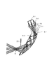
図3は本発明の観察光学系を用いた画像表示装置の概略配置図である。図中31は本発明の観察光学系を観察者の頭部に装着するための支持部で、例えばベルトと光学系保持部を支持するための支持部材により構成されている。32は光学系2を保持する保持部(筐体)、34は表示手段1の表示部の駆動を行う回路部、33は集光レンズ3並びに表示手段1、回路部34を保持する保持部である。図3に示す様に、本発明の観察光学系を支持部31を介して観察者の頭部に装着する際、観察光学系の光学素子2の保持部32を支持部31より下方に、集光レンズ3及び表示手段等の保持部33を上方に配置することにより、重量バランスの良い画像表示装置を構成することが可能である。即ち、観察光学系が該光学素子2以外に集光レンズ(リレー光学系)3を有し、該集光レンズ3と該光学素子2とを支持部に対して上下に配置することにより重量バランスの良い観察光学系が得られる。
【0025】
以下に本発明にかかる3つの数値実施例の構成データを示す。
【0026】
尚、構成データ中、R は面の曲率半径、D は面間隔、N は媒質の屈折率、νは媒質のアッベ数であり、θは前面の光軸に対する面の光軸の傾き、YDは光軸に対する垂直方向の面の移動量、ZDは光軸方向の面の移動量を示す。
【0027】
また、ASP と示された面は以下の式で表される非球面であり、記載のない係数は 0である。
【0028】

【0029】
【数1】
[数値実施例1]
図4は数値実施例1の垂直方向の断面図である。その構成データを以下に示す。
【0030】
α:-5.40゜、β:25.46゜
2β+α=45.52 ゜
ra 86.011mm
rc 173.836mm
|ra/rc| = 0.495
Da=11.77mm、Dc=21.28mm
[数値実施例2]
図5は数値実施例2の垂直方向の断面図である。その構成データを以下に示す。
【0031】
α:20.00゜、β:20.84゜
2β+α=61.68 ゜
ra= 86.619mm
rc=166.355mm
|ra/rc|= 0.521
Da=13.68mm、Dc=19.84mm
[数値実施例3]
図6は数値実施例3の垂直方向の断面図である。その構成データを以下に示す。
【0032】
α:27.07゜、β:22.15゜
2β+α=71.37 ゜
ra= 90.584mm
rc= 68.158mm
|ra/rc|= 1.329
Da=10.56mm、Dc=15.02mm
以上のように、本発明の各数値実施例は原画像からの光束を光学素子を介して観察者の眼球の位置する射出瞳に導く観察光学系において,屈折面として作用する第1の面A 、光束を2回反射する面として作用する第2の面B 、全反射面及び屈折面として作用する第3の面C の少なくとも3つの光学作用面を有する光学素子を観察光学系中に設けることにより、原画像上の各点からの光束が、第1の面A から入射して、第2の面B での1回目の反射から第3の面C へ向かう光束群を横切る様に中間結像面を形成することにより、垂直方向画角±20゜程度の広視野画角で、薄型で軽量な観察光学系となっている。
【0033】
更に、該観察光学系は前記光学素子以外に集光レンズ(リレー光学系)を有し、該集光レンズと該光学素子とを支持部に対して上下に配置することにより重量バランスの良い画像表示装置を構成できる。
【0034】
更に、上記の各数値実施例のいずれか1つの観察光学系を観察者の左右の眼に対応して夫々一つずつ配置して画像表示装置を構成すれば、軽量で使用感の良い画像表示装置が得られ、更に左右の表示手段に表示する原画像を左右の視差画像とすれば軽量な立体画像表示装置が得られる。
【0035】
【発明の効果】
本発明は以上の構成により、実像タイプでありながら、前後方向に極めて薄型で、小型・広視野角の観察光学系を達成する。
【0036】
更に、表示手段及びリレー光学系を画像表示装置の支持部より上に配置し、光学素子を該支持部より下に配置することで重量バランスの良い画像表示装置を構成できる観察光学系を達成する。
【図面の簡単な説明】
【図1】 本発明の観察光学系の実施形態1の基本構成図
【図2】 本発明の観察光学系の基準光線と各面との関係の説明図
【図3】 本発明の観察光学系を用いた画像表示装置の概略配置図
【図4】 本発明の数値実施例1の垂直方向断面図
【図5】 本発明の数値実施例2の垂直方向断面図
【図6】 本発明の数値実施例3の垂直方向断面図
【符号の説明】
1・・・表示手段
2・・・光学素子
3・・・集光レンズ(リレー光学系)
4・・・射出瞳(観察者の瞳が位置する)
A・・・第1の面
B・・・第2の面
C・・・第3の面
8・・・中間結像面
9・・・筐体の壁
w・・・覗窓
w0 ・・覗窓の中心
31・・・支持部
32・・・保持部
33・・・保持部
34・・・回路部[0001]
BACKGROUND OF THE INVENTION
The present invention relates to an observation optical system, and is particularly suitable for a head-mounted image display device called by a name such as a glasses-type display or a head-mounted display.
[0002]
[Prior art]
Conventionally, an image display device has been proposed in which display means such as a CRT and a liquid crystal display (LCD) are arranged in the vicinity of the observer's head so that images displayed on the CRT and LCD can be observed.
[0003]
For example, display devices according to U.S. Pat. No. 4,081,209, U.S. Pat. No. 4,969,724, JP-A-58-78116, JP-A-2-97516, JP-A-3-101709, and the like are disclosed.
[0004]
Japanese Patent Laid-Open No. 3-101709 discloses a so-called real image type image display device that is relatively easy to see, in which an original image displayed on a display means is re-imaged as an intermediate image, and an observer observes this intermediate image with an optical system. is doing.
[0005]
On the other hand, in U.S. Pat.No. 4,081,209, U.S. Pat.No. 4,969,724, JP-A-58-78116, and JP-A-2-2751616, although it is slightly inferior in viewability, An advantageous virtual image observation type image display device that does not form an intermediate image in the middle of an optical system is disclosed.
[0006]
[Problems to be solved by the invention]
In the image display device disclosed in Japanese Patent Laid-Open No. 3-101709, there is a problem that the size of the device is increased because an optical lens for re-imaging is used.
[0007]
In addition, the image display devices disclosed in U.S. Pat.No. 4,081,209, U.S. Pat.No. 4,969,724, Japanese Patent Laid-Open No. 58-78116, and Japanese Patent Laid-Open No. 2-227516 are certainly smaller than the real image type. However, it was still not small enough.
[0008]
Among these, those disclosed in Japanese Patent Application Laid-Open No. 58-78116 are relatively small, but the thickness of the observer's eyes in the optical axis direction is still thick. Further, it is described that optical distortion, astigmatism, coma and the like occur in an observed image.
[0009]
An object of the present invention is to provide an observation optical system that is a real image type but is extremely thin in the front-rear direction, and has a small size and a wide viewing angle.
[0010]
Furthermore, it is possible to provide an observation optical system that can constitute an image display device having a good weight balance by disposing the display means and the relay optical system above the support portion of the image display device and disposing the optical element below the support portion. Objective.
[0011]
[Means for Solving the Problems]
The observation optical system according to the first aspect of the present invention guides the light beam from the original image displayed on the display means to the exit pupil predetermined for the optical system via the optical system, and the position of the exit pupil. In the observation optical system in which the observer's pupil is substantially positioned to allow the observer to visually recognize the magnified virtual image of the original image, the observation optical system is a first surface that acts as a refractive surface and a first surface that acts as a reflective surface. An optical element having at least three optical action surfaces of a second surface, a total reflection surface and a third surface acting as a refracting surface, and a condensing lens disposed between the display means and the optical element, The light beam from the original image is incident on the optical element from the first surface via the condenser lens, passes through the reflection on the second surface and the total reflection on the third surface. The optical element is emitted from the third surface, and the original image is placed in the optical element. When the intermediate image is formed as a real image and a light beam that exits from the center of the display surface of the display unit and passes through the center of the exit pupil is used as a reference light beam, the optical element reflects the reference light beam twice. This surface is such that at least a part of the reflected portion of the light beam from the first original image on this surface overlaps with the reflected portion of the light beam from the second original image, and the reference light beam It is characterized by a curved surface decentered with respect to.
The invention of
According to a third aspect of the present invention, in the second aspect of the present invention, the curved surface arranged eccentrically with respect to the reference beam in the condenser lens is a transmission surface.
According to a fourth aspect of the present invention, in the first, second, or third aspect of the invention, the condensing lens condenses the light flux from the original image and makes it incident on the optical element.
The invention of
According to a sixth aspect of the present invention, in the first aspect of the present invention, the light beam from the original image passes through the first surface and enters the optical element, and then the second surface. Reflected by the third surface, totally reflected by the third surface and directed to the second surface, reflected again by the second surface and directed to the third surface, 3 is transmitted through the
The following conditional expression:
30 ° ≦ 2β + α ≦ 90 ° −10 ° ≦ α ≦ 30 ° is satisfied.
According to a seventh aspect of the present invention, in the first aspect of the present invention, the light beam from the original image passes through the first surface and enters the optical element, and then the second surface. Reflected by the third surface, totally reflected by the third surface and directed to the second surface, reflected again by the second surface and directed to the third surface, The second surface at the incident point when the reference light beam is reflected on the second surface for the first time by being transmitted through the
0 <| ra / rc | <1.5
It is characterized by satisfying.
An image display device according to an eighth aspect of the present invention is an image display device comprising: the observation optical system according to any one of the first to seventh aspects; and a support unit for mounting the observation optical system on an observer's head, The observation optical system is mounted on the observer's head so that the relay optical system is above the support and the optical element of the observation optical system is below the support.
An image display apparatus according to a ninth aspect of the invention is characterized in that the observation optical systems according to the first to seventh aspects are arranged one by one in correspondence with the left and right eyes of the observer.
[0012]
DETAILED DESCRIPTION OF THE INVENTION
FIG. 1 is a basic configuration diagram of
[0013]
The operation of this embodiment will be described. A light beam from an image displayed on the display means 1 is first refracted by the condensing
[0014]
At this time, when the light beam from the display means 1 goes from the first reflection by the second surface B of the
[0015]
In the present embodiment, at least three of the first surface A that acts as a refractive surface, the second surface B that acts as a surface that reflects the light beam twice, the total reflection surface, and the third surface C that acts as a refractive surface. By providing an optical element having an optical action surface in the observation optical system, a light beam from each point on the original image is incident from the
[0016]
In addition, the present embodiment has a condensing lens (relay optical system) in addition to the optical element, and the light beam from the original image is condensed by the condensing lens so as to be incident on the optical element. The effective diameter of the incident surface of the optical element is reduced.
[0017]
In addition, this embodiment limits the overall length by making at least a part of the first reflection part and the second reflection part in the second surface B in the optical element in particular, that is, the parts overlap each other . Furthermore, a light observation optical system is provided.
[0018]
Hereinafter, the present embodiment will be described in more detail based on the configuration in the vertical sectional direction. The observation optical system of the present invention does not have an optical axis as in a normal optical system. Therefore, in the observation optical system of the present invention, the “reference beam” is set to clarify the configuration. The reference light beam referred to in the present invention is a light beam that exits from the center of the display surface of the
[0019]
FIG. 2 is an explanatory diagram of the relationship between the reference light beam and each surface of the observation optical system of the present invention. When the reference ray is reflected, totally reflected, or refracted by the
[0020]
In the present embodiment, α and β are the following conditional expressions:
30 ° ≦ 2β + α ≦ 90 ° (Condition 1)
It is set to satisfy. The lower limit value of (Condition 1) relates to the condition of total reflection on the third surface C. If the lower limit is exceeded, it is very difficult to cause total reflection on the third surface C. On the other hand, if the upper limit is exceeded, the light flux with a lower field angle of view with respect to the reference light beam tends to be insufficient, and the performance deteriorates.
[0021]
Furthermore, at this time, α is −10 ° ≦ α ≦ 30 ° (Condition 2)
Is preferably set. Exceeding the lower limit of (Condition 2) is not preferable because the thickness in the direction perpendicular to the third surface C of the
[0022]
Also, the radius of curvature of the vertical section (in the paper) at the incident point c when the reference ray is reflected on the second surface B for the first time is r c , and the reference ray is reflected on the second surface B for the second time. when the radius of curvature of the vertical cross-section (in the plane) at an incident point a when a r a, these
0 <| r a / r c | <1.5 (conditional expression 3)
It is desirable to set so as to satisfy If the condition of (Condition 3) is exceeded, the length in the direction parallel to the third surface C of the
[0023]
In the present embodiment, since the
[0024]
FIG. 3 is a schematic layout diagram of an image display apparatus using the observation optical system of the present invention. In the figure,
[0025]
The configuration data of three numerical examples according to the present invention will be shown below.
[0026]
In the configuration data, R is the radius of curvature of the surface, D is the surface spacing, N is the refractive index of the medium, ν is the Abbe number of the medium, θ is the inclination of the optical axis of the surface with respect to the optical axis of the front surface, and YD is The amount of movement of the surface in the direction perpendicular to the optical axis, ZD, indicates the amount of movement of the surface in the direction of the optical axis.
[0027]
The surface indicated as ASP is an aspherical surface expressed by the following formula, and the coefficient not described is 0.
[0028]
[0029]
[Expression 1]
[Numerical Example 1]
4 is a vertical sectional view of Numerical Example 1. FIG. The configuration data is shown below.
[0030]
2β + α = 45.52 ゜
r a 86.011mm
r c 173.836mm
│r a / r c | = 0.495
Da = 11.77mm, Dc = 21.28mm
[Numerical Example 2]
FIG. 5 is a vertical sectional view of Numerical Example 2. The configuration data is shown below.
[0031]
2β + α = 61.68 °
r a = 86.619mm
r c = 166.355mm
| R a / r c | = 0.521
Da = 13.68mm, Dc = 19.84mm
[Numerical Example 3]
FIG. 6 is a cross-sectional view of Numerical Example 3 in the vertical direction. The configuration data is shown below.
[0032]
2β + α = 71.37 ゜
r a = 90.584mm
r c = 68.158mm
| R a / r c | = 1.329
Da = 10.56mm, Dc = 15.02mm
As described above, in each numerical example of the present invention, the first surface A that acts as a refractive surface in the observation optical system that guides the light beam from the original image to the exit pupil where the eyeball of the observer is positioned through the optical element. An observation optical system is provided with an optical element having at least three optical action surfaces: a second surface B that acts as a surface that reflects the light beam twice, a third surface C that acts as a total reflection surface and a refracting surface. As a result, the intermediate beam is formed so that the light flux from each point on the original image enters from the first surface A and crosses the light flux group from the first reflection on the second surface B toward the third surface C. By forming the image plane, the observation optical system is thin and lightweight with a wide field angle of view of about ± 20 ° in the vertical direction.
[0033]
Further, the observation optical system has a condensing lens (relay optical system) in addition to the optical element, and an image with a good weight balance is provided by arranging the condensing lens and the optical element above and below the support portion. A display device can be configured.
[0034]
Furthermore, if an image display device is configured by arranging any one observation optical system in each of the numerical examples described above corresponding to the left and right eyes of the observer, the image display is light and easy to use. If the original image displayed on the left and right display means is the left and right parallax images, a lightweight stereoscopic image display device can be obtained.
[0035]
【The invention's effect】
With the above configuration, the present invention achieves an observation optical system that is a real image type, is extremely thin in the front-rear direction, and has a small size and a wide viewing angle.
[0036]
Furthermore, an observation optical system capable of constructing an image display device having a good weight balance by arranging the display means and the relay optical system above the support portion of the image display device and arranging the optical element below the support portion is achieved. .
[Brief description of the drawings]
FIG. 1 is a basic configuration diagram of
DESCRIPTION OF
4 ... Exit pupil (the observer's pupil is located)
A ... first surface B ... second surface C ...
31 ... Supporting part
32 ・ ・ ・ Holding part
33 ・ ・ ・ Holding part
34 ・ ・ ・ Circuit part
Claims (9)
該観察光学系は、屈折面として作用する第1の面、反射面として作用する第2の面、全反射面及び屈折面として作用する第3の面の少なくとも3つの光学作用面を有する光学素子と、前記表示手段と前記光学素子の間に配置された集光レンズを有し、
前記原画像からの光束は、前記集光レンズを介して前記第1の面より前記光学素子に入射し、前記第2の面での反射と前記第3の面での全反射とを経た後、前記第3の面より前記光学素子を射出すると共に、前記光学素子内に前記原画像の中間像が実像として形成され、
前記表示手段の表示面の中心から射出して前記射出瞳の中心を通る光線を基準光線とした場合に、前記光学素子は、該基準光線が2回反射する面を有し、この面は、この面での1回目の前記原画像からの光束の反射部位と2回目の前記原画像からの光束の反射部位との少なくとも一部分が重なっており、且つ該基準光線に対して偏心した曲面であることを特徴とする観察光学系。The light beam from the original image displayed on the display means is guided to the exit pupil predetermined for the optical system via the optical system, and the observer's pupil is substantially positioned at the position of the exit pupil. In an observation optical system that allows an observer to view an enlarged virtual image of the original image,
The observation optical system has an optical element having at least three optical action surfaces: a first surface acting as a refracting surface, a second surface acting as a reflecting surface, a total reflection surface, and a third surface acting as a refracting surface. When it has placed a condensing lens between the display means and the optical element,
The light beam from the original image is incident on the optical element from the first surface via the condenser lens, passes through the reflection on the second surface and the total reflection on the third surface. The optical element is emitted from the third surface , and an intermediate image of the original image is formed as a real image in the optical element .
When a light beam that exits from the center of the display surface of the display means and passes through the center of the exit pupil is used as a reference light beam, the optical element has a surface on which the reference light beam is reflected twice . at least partially overlaps the reflecting part of the light beam from the reflective portion and the second of the original image of the light beam from the first of the original image in this plane, is in and curved surface decentered with respect to the reference ray An observation optical system characterized by that.
αを前記基準光線が前記第3の面で屈折する際の入射点における面法線に対する該基準光線の傾き角、βを該基準光線が前記第2の面において2回目の反射をする際の入射点における面法線に対する該基準光線の傾き角とした場合、
以下の条件式:
30゜≦2β+α≦90゜
−10゜≦α≦30゜
を満足することを特徴とする請求項1乃至5のいずれか1項の観察光学系。The light flux from the original image is transmitted through the first surface and incident on the optical element, and then directed reflected by said second surface to the third surface, and total reflected by the third surface Te directed to said second side, and again reflected by the second surface directed to said third surface, is guided in the third the exit pupil is transmitted through the surface and exit the optical element ,
α is the inclination angle of the reference ray with respect to the surface normal at the incident point when the reference ray is refracted by the third surface , and β is the second reflection of the reference ray on the second surface . When the inclination angle of the reference ray with respect to the surface normal at the incident point,
The following conditional expression:
Any one of the observation optical system of claims 1 to 5, characterized by satisfying 30 ° ≦ 2β + α ≦ 90 ° -10 ° ≦ alpha ≦ 30゜Wo.
rcを前記基準光線が前記第2の面において1回目の反射をする際の入射点における前記第2の面の垂直断面の曲率半径、raを前記基準光線が前記第2の面において2回目の反射をする際の入射点における前記第2の面の垂直断面の曲率半径として、以下の条件式:
0<|ra/rc|<1.5
を満足することを特徴とする請求項1乃至6のいずれか1項の観察光学系。The light flux from the original image is transmitted through the first surface and incident on the optical element, and then directed reflected by said second surface to the third surface, and total reflected by the third surface Te directed to said second side, and again reflected by the second surface directed to said third surface, is guided in the third the exit pupil is transmitted through the surface and exit the optical element ,
rc is the radius of curvature of the vertical cross section of the second surface at the point of incidence when the reference beam is reflected for the first time on the second surface , and ra is the second time the reference beam is reflected on the second surface . As the radius of curvature of the vertical cross section of the second surface at the incident point at the time of reflection, the following conditional expression:
0 <| ra / rc | <1.5
The observation optical system according to any one of claims 1 to 6 , wherein:
Priority Applications (1)
| Application Number | Priority Date | Filing Date | Title |
|---|---|---|---|
| JP33031296A JP3787399B2 (en) | 1996-11-25 | 1996-11-25 | Observation optical system |
Applications Claiming Priority (1)
| Application Number | Priority Date | Filing Date | Title |
|---|---|---|---|
| JP33031296A JP3787399B2 (en) | 1996-11-25 | 1996-11-25 | Observation optical system |
Publications (2)
| Publication Number | Publication Date |
|---|---|
| JPH10153748A JPH10153748A (en) | 1998-06-09 |
| JP3787399B2 true JP3787399B2 (en) | 2006-06-21 |
Family
ID=18231235
Family Applications (1)
| Application Number | Title | Priority Date | Filing Date |
|---|---|---|---|
| JP33031296A Expired - Fee Related JP3787399B2 (en) | 1996-11-25 | 1996-11-25 | Observation optical system |
Country Status (1)
| Country | Link |
|---|---|
| JP (1) | JP3787399B2 (en) |
Cited By (6)
| Publication number | Priority date | Publication date | Assignee | Title |
|---|---|---|---|---|
| EP2631695A1 (en) | 2012-02-24 | 2013-08-28 | Seiko Epson Corporation | Virtual image display apparatus |
| WO2015033534A1 (en) | 2013-09-03 | 2015-03-12 | Seiko Epson Corporation | Virtual image display apparatus |
| US9013796B2 (en) | 2013-02-13 | 2015-04-21 | Seiko Epson Corporation | Virtual image display device |
| US9188782B2 (en) | 2013-02-13 | 2015-11-17 | Seiko Epson Corporation | Virtual image display device |
| US9945997B2 (en) | 2013-09-03 | 2018-04-17 | Seiko Epson Corporation | Virtual image display apparatus with curved surface having both positive and negative curvature and functioning as both reflection surface and refraction surface |
| US9977238B2 (en) | 2012-02-24 | 2018-05-22 | Seiko Epson Corporation | Virtual image display apparatus |
Families Citing this family (11)
| Publication number | Priority date | Publication date | Assignee | Title |
|---|---|---|---|---|
| JP4372891B2 (en) * | 1999-06-22 | 2009-11-25 | オリンパス株式会社 | Video display device |
| US7019909B2 (en) | 2001-11-14 | 2006-03-28 | Canon Kabushiki Kaisha | Optical system, image display apparatus, and image taking apparatus |
| US7012756B2 (en) | 2001-11-14 | 2006-03-14 | Canon Kabushiki Kaisha | Display optical system, image display apparatus, image taking optical system, and image taking apparatus |
| JP4218553B2 (en) | 2004-03-08 | 2009-02-04 | ソニー株式会社 | Image display device |
| JP4636808B2 (en) * | 2004-03-31 | 2011-02-23 | キヤノン株式会社 | Image display device |
| JP2006238256A (en) * | 2005-02-28 | 2006-09-07 | Pioneer Electronic Corp | Amplifying apparatus |
| JP5031272B2 (en) | 2006-06-06 | 2012-09-19 | キヤノン株式会社 | Display optical system and image display apparatus having the same |
| JP6373232B2 (en) | 2015-07-23 | 2018-08-15 | キヤノン株式会社 | Image display device |
| JP6395674B2 (en) | 2015-07-23 | 2018-09-26 | キヤノン株式会社 | Image display device and imaging device |
| US11550095B2 (en) * | 2018-10-26 | 2023-01-10 | Google Llc | Curved optical see-through thin freeform lightguide with large field of view in eyewear formfactor |
| CN115427843A (en) * | 2020-04-24 | 2022-12-02 | 松下知识产权经营株式会社 | Optical system |
-
1996
- 1996-11-25 JP JP33031296A patent/JP3787399B2/en not_active Expired - Fee Related
Cited By (9)
| Publication number | Priority date | Publication date | Assignee | Title |
|---|---|---|---|---|
| EP2631695A1 (en) | 2012-02-24 | 2013-08-28 | Seiko Epson Corporation | Virtual image display apparatus |
| US9436010B2 (en) | 2012-02-24 | 2016-09-06 | Seiko Epson Corporation | Virtual image display apparatus having prism with specific polynomial relationship between prism surface shapes |
| US9977238B2 (en) | 2012-02-24 | 2018-05-22 | Seiko Epson Corporation | Virtual image display apparatus |
| US9013796B2 (en) | 2013-02-13 | 2015-04-21 | Seiko Epson Corporation | Virtual image display device |
| US9188782B2 (en) | 2013-02-13 | 2015-11-17 | Seiko Epson Corporation | Virtual image display device |
| WO2015033534A1 (en) | 2013-09-03 | 2015-03-12 | Seiko Epson Corporation | Virtual image display apparatus |
| US9829709B2 (en) | 2013-09-03 | 2017-11-28 | Seiko Epson Corporation | Virtual image display apparatus |
| US9945997B2 (en) | 2013-09-03 | 2018-04-17 | Seiko Epson Corporation | Virtual image display apparatus with curved surface having both positive and negative curvature and functioning as both reflection surface and refraction surface |
| US10310270B2 (en) | 2013-09-03 | 2019-06-04 | Seiko Epson Corporation | Virtual image display apparatus |
Also Published As
| Publication number | Publication date |
|---|---|
| JPH10153748A (en) | 1998-06-09 |
Similar Documents
| Publication | Publication Date | Title |
|---|---|---|
| JP3787399B2 (en) | Observation optical system | |
| JP3599828B2 (en) | Optical device | |
| JP3382683B2 (en) | Concentric optical system | |
| JP3683317B2 (en) | Image display device | |
| JP3924348B2 (en) | Image display device | |
| JP3865906B2 (en) | Image display device | |
| US6201648B1 (en) | Optical system | |
| US6222676B1 (en) | Image display apparatus | |
| US6519090B2 (en) | Eyepiece optical system | |
| US6181475B1 (en) | Optical system and image display apparatus | |
| JP3392929B2 (en) | Video display device | |
| JP3645618B2 (en) | Image display device | |
| JPH09219832A (en) | Image display | |
| JPH09258104A (en) | Optical system | |
| JPH10161018A (en) | Optical system | |
| JPH1090603A (en) | Endscopic optical system | |
| JPH0961747A (en) | Picture display device | |
| JPH08146341A (en) | Image display device | |
| JP3929153B2 (en) | Imaging optics | |
| JP2000241705A (en) | Video display optical system | |
| US6687057B1 (en) | Image display apparatus having rotationally asymmetric phase distribution | |
| US20020176175A1 (en) | Real image type zoom finder | |
| JP3559624B2 (en) | Image display device | |
| JPH0990270A (en) | Head-or face-mounted type picture display device | |
| JP2000241706A (en) | Prism optical system |
Legal Events
| Date | Code | Title | Description |
|---|---|---|---|
| A977 | Report on retrieval |
Free format text: JAPANESE INTERMEDIATE CODE: A971007 Effective date: 20050801 |
|
| A131 | Notification of reasons for refusal |
Free format text: JAPANESE INTERMEDIATE CODE: A131 Effective date: 20050913 |
|
| A521 | Written amendment |
Free format text: JAPANESE INTERMEDIATE CODE: A523 Effective date: 20051114 |
|
| A131 | Notification of reasons for refusal |
Free format text: JAPANESE INTERMEDIATE CODE: A131 Effective date: 20051220 |
|
| A521 | Written amendment |
Free format text: JAPANESE INTERMEDIATE CODE: A523 Effective date: 20060216 |
|
| TRDD | Decision of grant or rejection written | ||
| A01 | Written decision to grant a patent or to grant a registration (utility model) |
Free format text: JAPANESE INTERMEDIATE CODE: A01 Effective date: 20060314 |
|
| A61 | First payment of annual fees (during grant procedure) |
Free format text: JAPANESE INTERMEDIATE CODE: A61 Effective date: 20060327 |
|
| R150 | Certificate of patent or registration of utility model |
Free format text: JAPANESE INTERMEDIATE CODE: R150 |
|
| FPAY | Renewal fee payment (event date is renewal date of database) |
Free format text: PAYMENT UNTIL: 20100331 Year of fee payment: 4 |
|
| FPAY | Renewal fee payment (event date is renewal date of database) |
Free format text: PAYMENT UNTIL: 20100331 Year of fee payment: 4 |
|
| FPAY | Renewal fee payment (event date is renewal date of database) |
Free format text: PAYMENT UNTIL: 20110331 Year of fee payment: 5 |
|
| FPAY | Renewal fee payment (event date is renewal date of database) |
Free format text: PAYMENT UNTIL: 20120331 Year of fee payment: 6 |
|
| FPAY | Renewal fee payment (event date is renewal date of database) |
Free format text: PAYMENT UNTIL: 20130331 Year of fee payment: 7 |
|
| FPAY | Renewal fee payment (event date is renewal date of database) |
Free format text: PAYMENT UNTIL: 20130331 Year of fee payment: 7 |
|
| FPAY | Renewal fee payment (event date is renewal date of database) |
Free format text: PAYMENT UNTIL: 20140331 Year of fee payment: 8 |
|
| LAPS | Cancellation because of no payment of annual fees |