JP3786355B2 - Spindle motor and recording disk drive device - Google Patents
Spindle motor and recording disk drive device Download PDFInfo
- Publication number
- JP3786355B2 JP3786355B2 JP2002025984A JP2002025984A JP3786355B2 JP 3786355 B2 JP3786355 B2 JP 3786355B2 JP 2002025984 A JP2002025984 A JP 2002025984A JP 2002025984 A JP2002025984 A JP 2002025984A JP 3786355 B2 JP3786355 B2 JP 3786355B2
- Authority
- JP
- Japan
- Prior art keywords
- hub
- spindle motor
- shaft
- peripheral surface
- dynamic pressure
- Prior art date
- Legal status (The legal status is an assumption and is not a legal conclusion. Google has not performed a legal analysis and makes no representation as to the accuracy of the status listed.)
- Expired - Fee Related
Links
Images

Landscapes
- Connection Of Motors, Electrical Generators, Mechanical Devices, And The Like (AREA)
- Sliding-Contact Bearings (AREA)
- Rotational Drive Of Disk (AREA)
- Holding Or Fastening Of Disk On Rotational Shaft (AREA)
- Motor Or Generator Frames (AREA)
Description
【0001】
【発明の属する技術分野】
本発明は、スピンドルモータ、特に、ハブとその中心孔内に嵌合されたシャフトとから構成される回転部材を有するスピンドルモータに関する。本発明は、さらに、前記スピンドルモータが採用された記録ディスク駆動装置に関する。
【0002】
【従来の技術】
ハードディスク等の記録ディスク駆動装置は、記録ディスクと同心に配置された回転駆動用のスピンドルモータを装置内に有している。このスピンドルモータは、主に、電機子コイルを有する静止部材と、コイルに対向するロータマグネットを有する回転部材と、回転部材を静止部材に回転自在に支持する軸受機構とから構成されている。
【0003】
このようなスピンドルモータの一例として、シャフト回転型のスピンドルモータが知られている。このスピンドルモータでは、回転部材はハブとその中心孔内に一端が嵌合されたシャフトを有しており、静止部材は回転部材のシャフトを内周側に収容する中空円筒状のスリーブを有している。ハブは、概ね、円板形状の部材であり、外周縁に軸線方向に延びる筒状部が形成されている。筒状部の内周側にはステータコイルが設けられ、外周側の鍔部には複数の記録ディスクが固定されている。記録ディスクの固定手段としては、記録ディスクを鍔部端面にクランプするためのクランプ部材と、それをハブに固定するためのねじ部材とから構成されている。このため、回転部材にはねじ部材が螺合するためのねじ孔が形成されていることになる。また、軸受機構としては、スリーブとシャフトとの間に例えば流体動圧軸受が形成されている。
【0004】
【発明が解決しようとする課題】
昨今の記録ディスク駆動装置が搭載されるパーソナルコンピュータ等の機器の小型化及び薄型化の傾向並びに記録ディスク駆動装置のディジタルカメラ等小型機器への応用等使用される製品の多様化によって、記録ディスクを回転駆動するスピンドルモータ自体も小型化並びに薄型化することが要求されている。したがって、スピンドルモータにおいては、回転部材であるハブの薄肉化が進んでいる。
【0005】
ハブの薄肉化が進むと、ディスク用クランプを回転部材に固定するためのネジ孔は、ハブに形成することができず、シャフトの端面に形成されるようになっている。そして、ディスク用クランプは、ねじ部材によって中心部分がたわまされることによって、その外周部からたわみ反力を記録ディスクの内周部に与えている。したがって、ハブの外周部は、常に、ディスク用クランプからのクランプ力によって、クランプ部材と反対側に押されている。
【0006】
このようにクランプ力が作用すると、ハブがたわみ変形してしまう。そのため、ハブ/シャフト間の精度(直角度)に狂いが生じRRO(Repeatable Run-Out:繰り返し振れ)が悪化したり、あるいはハブ/シャフト間の締結が外れたりするという問題が生じる。
特に、ハブの薄肉化が進むと、ハブ/シャフトの締結区間が短くなるため、シャフトとハブの締結強度が十分に得られなくなる。そのため、前記問題がより顕著になることが考えられる。
【0007】
以上に述べたシャフトとハブの締結強度低下の問題については、様々な対策が考えられるが、各対策はそれぞれ問題を包含している。例えば、ハブ/シャフトの圧入時の締め代を大きくする方法では、ハブ/シャフトへの負担(締結の残留応力等)が大きくなり、塑性変形が生じることで、かえって回転精度を悪化させる懸念がある。また、クランプ力を小さくする方法では、記録ディスクのズレ,飛散が懸念される。
【0008】
本発明の課題は、ハブの中心孔に締結された回転シャフトの一端の端面にディスク用クランプをたわませるためのねじが螺合するためのねじ孔が形成されたスピンドルモータにおいて、ハブに作用するクランプ力によるハブ/シャフト締結部の不具合を適切に解消することにある。
【0009】
【課題を解決するための手段】
請求項1に記載のスピンドルモータは、静止部材と、ハブと、シャフトと、ステータコイルと、ロータマグネットとを備えている。静止部材は中空円筒状のスリーブを有する。ハブは、中心孔が形成された円板状部と、円板状部の内周縁から軸線方向に突出する筒状部とを有する。シャフトは、スリーブの内周面の半径方向内側に配置された部材であって、一端が筒状部の内周面に嵌合されている。シャフトの一端の端面には、ディスク用クランプをたわませるためのねじ部材が螺合するねじ孔が形成されている。軸受機構は、ハブ及びシャフトを静止部材に対して回転自在に支持するための機構である。ステータコイルは静止部材に固定されている。ロータマグネットは、ステータコイルに対向するようにハブに固定され、ステータコイルと協働して回転磁界を発生する。
【0010】
このスピンドルモータでは、記録ディスク駆動装置において、ねじ部材はシャフトのねじ孔に螺合することで、ディスク用クランプをたわませている。このため、ディスク用クランプは記録ディスクをハブとの間で挟みつけている。
シャフトにねじ孔を形成することで、ハブの円板状部を薄肉化することができるが、その一方でこの構成によってハブに対するクランプ力がハブの外周部を軸線方向片側に押し付けるように作用している。そのため、クランプによってハブはたわみ変形し、ハブがシャフトに対して嵌合部において傾き、嵌合部の軸線方向先端側で締結が外れるという事態が起こりやすいと考えられる。
【0011】
しかし、このスピンドルモータでは、ハブの筒状部がシャフトに締結されることで、ハブ/シャフト間の接触面積を十分に確保することができ、十分なハブ/シャフト締結強度を得ることができる。したがって、クランプ力が作用したときにハブとシャフトの締結が外れにくくなっている。
請求項2記載のスピンドルモータでは、請求項1において、軸受機構は、筒状部の外周面とスリーブのラジアル内周面との間に潤滑流体を保持すると共に、前記潤滑流体に動圧を誘起する動圧発生用溝を設けることで構成された第1ラジアル軸受部を含んでいる。
【0012】
このスピンドルモータでは、第1ラジアル軸受部は、ハブの筒状部の外周面において形成されているため、ラジアル軸受部の径が従来に比べて大きくなっている。このため、ラジアル軸受部において周速が増し、発生する動圧が大きくなる。
また、ハブとシャフトの締結強度を向上させるために締結区間を単に長く設定するだけでは、ハブ/シャフトの締結部の近傍に設けられたラジアル軸受部の寸法が制限されることになり、その結果軸受剛性等必要な回転支持力を確保することが困難になってしまう。それに対してこのスピンドルモータの構成では、第1ラジアル軸受部はハブの筒状部の外周面において形成されているため、十分な軸受剛性を確保することができる。
【0013】
請求項3に記載のスピンドルモータでは、請求項2において、軸受機構は、シャフトの外周面においてハブの筒状部に覆われていない部分とスリーブのラジアル内周面との間に潤滑油を保持すると共に、潤滑流体に動圧を誘起する動圧発生用溝を設けることで構成された第2ラジアル軸受部をさらに含んでいる。
このスピンドルモータでは、第2ラジアル軸受部の径は第1ラジアル軸受部の径より小さく従来と同等であるが、軸受機構全体ではラジアル動圧は大きくなっている。
【0014】
請求項4に記載のスピンドルモータでは、請求項1において、軸受機構は、筒状部の外周面とスリーブの2つのラジアル内周面との間に潤滑流体を保持すると共に、潤滑流体に動圧を誘起する動圧発生用溝を設けることで構成された第1及び第2ラジアル軸受部を含んでいる。
このスピンドルモータでは、第1及び第2ラジアル軸受部は筒状部の外周面に形成されているため、ラジアル軸受部の径が従来に比べて大きくなっている。このため、ラジアル軸受部において周速が増し、発生する動圧が大きくなる。
【0015】
請求項5に記載のスピンドルモータでは、請求項4において、筒状部の外周面において第1及び第2ラジアル軸受を構成する部分の外径は同一であり、スリーブの2つのラジアル内周面の内径は同一である。
このスピンドルモータでは、2つのラジアル軸受部の同軸度が向上している。
請求項6に記載のスピンドルモータでは、請求項1〜5のいずれかにおいて、軸受機構は、シャフトのスラスト面とスリーブのスラスト面との間に潤滑流体を保持すると共に、潤滑流体に動圧を誘起する動圧発生用溝を設けることで構成されたスラスト軸受部をさらに含んでいる。
【0016】
このスピンドルモータでは、スラスト軸受部によってスラスト動圧を得ることができる。
請求項7に記載の記録ディスク駆動装置は、ハウジングと、ハウジングの内部に固定された請求項1〜6のいずれかに記載の前記スピンドルモータと、ハブの円板状部に固定された情報を記録できる円板状記録媒体と、記録媒体の所要の位置に情報を書込又は読み出すための情報アクセス手段とを備えている。
【0017】
この記録ディスク駆動装置では、前述のシャフトとハブの締結強度が向上したスピンドルモータ備えていることによって、記録媒体を安定して回転させることができる。
請求項8に記載の記録ディスク駆動装置は、請求項7において、シャフトのねじ孔に螺合するねじ部材と、ねじ部材によってたわまされ記録媒体をハブにクランプするディスク用クランプとをさらに備えている。
【0018】
この記録ディスク駆動装置では、前述のシャフトとハブの締結強度が向上したスピンドルモータ備えていることによって、記録媒体を安定して回転させることができる。
【0019】
【発明の実施の形態】
1.第1実施形態
(1)スピンドルモータ全体の構成
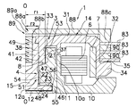
図1は本発明の一実施形態としてのスピンドルモータ1の概略構成を模式的に示す縦断面図である。このスピンドルモータ1は記録ディスク駆動用スピンドルモータであり、ハードディスク等の記録ディスク駆動装置の一部を構成している。
【0020】
なお、図1に示すO−Oがスピンドルモータ1の回転軸線である。また、本実施形態の説明では便宜上図1の上下方向を「軸線上下方向」とするが、スピンドルモータ1の実際の取付状態における方向を限定するものではない。
図1において、このスピンドルモータ1は、主に、静止部材2と、回転部材3と、回転部材3を静止部材2に回転自在に支持するための軸受機構4とを備えている。スピンドルモータ1は、さらに、静止部材2に固定されたステータ6と、回転部材3に固定されたロータマグネット7を備えており、両部材によって、回転部材3に対して回転力を与えるための磁気回路部が構成されている。
【0021】
(2)静止部材
静止部材2は、ブラケット10と、このブラケット10の中央開口内に固定されたスリーブ11とから構成されている。より詳細には、ブラケット10の中央開口縁には軸線方向上側に延びる筒部10aが形成されており、その内周面にスリーブ11の外周面が嵌合されている。また、ステータ6は筒部10aの外周面に固定されている。
【0022】
スリーブ11は、中空円筒状の部材であり、その略中央部には、軸線方向に貫通する貫通孔51が形成されている。スリーブ11の貫通孔51の内周面は、軸線方向上側から下側に向かって以下の順番で並んだ、第1ラジアル内周面53、第2ラジアル内周面54及び下部内周面55を有している。第1及び第2ラジアル内周面53,54は、軸受機構4の各ラジアル軸受部を構成している(後述)。スリーブ11の貫通孔51の下端は、スラストカバー12によって閉じられている。
【0023】
(3)回転部材
回転部材3は、軸受機構4を介してスリーブ11に回転自在に支持された部材であって、外周部に記録ディスク83が載置されるロータハブ14と、ロータハブ14の内周側に位置し、軸受機構4を介してスリーブ11に軸支されるシャフト15とを備えている。
【0024】
ロータハブ14は、概ね円板状の部材であり、静止部材2やステータ6の上方に近接して配置されている。さらに詳細には、ロータハブ14は、主に、円板状部31と、円板状部31の外周縁から軸線方向下側に延びる筒状部32と、円板状部31の内周縁から軸線方向下側に延びる筒状部33とから構成されている。筒状部32,33はともに円筒状である。
【0025】
筒状部32の内周面には接着等の手段によってロータマグネット7が固定されている。ロータマグネット7は、ステータ6に半径方向に微小間隙をもって対向して配置され、ステータ6と協働して回転磁界を発生する。つまり、ステータ6のコイルに通電することにより、ステータ6とロータマグネット7との電磁相互作用により、回転部材3にトルクが作用する。
【0026】
筒状部32の先端部には外周側に延びる鍔部34が形成されている。この鍔部34は、後述するディスク用クランプ88からのクランプ力を受けるための軸線方向上側端面35を有している。
(4)ハブとシャフトの締結構造
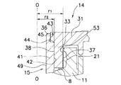
ハブ14とシャフト15は、シャフト15の上端がハブ14の中心孔すなわちその内周面に嵌合することで互いに締結されている。より具体的には、図2に示すように、シャフト15の上側部41の外周面42が筒状部33の内周面38に圧入されている。なお、両周面間には締結強度向上のため接着剤が供給されていてもよい。
【0027】
シャフト15の上側部41の先端外周側には、段差部43が形成されている。段差部43は、軸線方向上側端面44と、外周面45とを有し、このため段差部43が形成された部分は、半径方向の肉厚が他の部分により短い筒状部分となっている。ハブ14の内周縁の軸線方向上側部分には、段差部43に対応して内周側突出部36が形成されている。突出部36は段差部43に当接しており、これによりハブ14とシャフト15との軸線方向位置決めがなされ、さらにシャフト15がハブ14に対して軸線方向上側に抜け出るのが防止されている。
【0028】
以上に述べた締結構造をさらに詳細に説明すると、筒状部33とは、円板状部31の軸線方向下側端面より突出した部分であり、その内周面全てがシャフト15の外周面42と密着している。
以上に述べた締結構造において、ハブ14の筒状部33に対してシャフト15が嵌合しているため、従来に比べて締結区間・接触面積が大きくなり、締結強度が向上している。また、ハブ14の筒状部33はシャフト15の肉厚の大きな部分(上側部41)に締結されているため、段差部43が形成された薄肉部分に締結されていた従来例に比べて、締め代を大きくすることができる。つまり、ハブ14とシャフト15の締結強度をさらに向上させることができる。
【0029】
このように、ハブ14とシャフト15の締結強度が向上するため、半径方向の衝撃がハブ14に加えられた場合でも、ハブ/シャフト間の精度(直角度)に狂いが生じにくい。
(5)軸受機構
軸受機構4は、回転部材3を静止部材2に対して、より具体的には、ハブ14及びシャフト15をスリーブ11に対して潤滑流体を介して回転自在に支持するための動圧流体軸受機構である。軸受機構4は、第1及び第2ラジアル軸受部21,22と、第1及び第2スラスト軸受部23,24とを有している。以下、スリーブ11,ハブ14及びシャフト15の構造に触れながら、各軸受部21〜24の構造を説明していく。
【0030】
▲1▼ラジアル軸受部
スリーブ11の第1ラジアル内周面53は、図2に示すように、筒状部33の外周面37との間に潤滑流体8が保持されるラジアル微小間隙を確保するように対向している。第1ラジアル内周面53には、潤滑流体8中に動圧を発生するためのヘリングボーン状動圧発生用溝が形成されている。このように、スリーブ11の第1ラジアル内周面53と、筒状部33の外周面37と、その間の潤滑流体8とによって、第1ラジアル軸受部21が構成されている。
【0031】
スリーブ11の第2ラジアル内周面54は、第1ラジアル内周面53より小径であり、シャフト15の外周面42の軸線方向下側部分(ハブ14の筒状部33に覆われていない部分)との間に潤滑流体8が保持されるラジアル微小間隙を確保するように対向している。第2ラジアル内周面54には、潤滑流体8中に動圧を発生するためのヘリングボーン状動圧発生用溝が形成されている。このように、スリーブ11の第2ラジアル内周面54と、シャフト15の外周面42と、その間の潤滑流体8とによって、第2ラジアル軸受部22が構成されている。
【0032】
以上に述べたように、第1ラジアル軸受部21がハブ14の筒状部33の外周面において形成されているため、第1ラジアル軸受部21の半径r1が第2ラジアル軸受部22の半径r2に比べて大きくなっている。したがって、第1ラジアル軸受部21では、周速が増し、発生する動圧が大きくなる。また、発生する動圧に余裕がある場合は、筒状部・スリーブ間の隙間寸法を大きくすることができるので、加工に対する要求精度が緩和され、歩留まりの改善や、加工コストの削減等、モータの低コスト化に寄与することができる。
【0033】
なお、第2ラジアル軸受部22の半径r2は、シャフト15の外周面42と等しいため、従来と同じ大きさであるが、第1ラジアル軸受部21の半径r1が大きくなっているため、軸受機構4全体ではラジアル動圧は大きくなっている。
また、ハブとシャフトの締結強度を向上させるために締結区間を単に長く設定するだけでは、ラジアル軸受部がハブ/シャフトの締結部の近傍に設けられているため、寸法が制限されることになり、その結果ラジアル軸受部において軸受剛性等必要な回転支持力を確保することが困難になってしまう。それに対してこのスピンドルモータ1の構成では、第1ラジアル軸受部21はハブ14の筒状部33の外周面において形成されているため、締結区間を十分に確保した上で十分な軸受剛性を確保することができる。
【0034】
▲2▼スラスト軸受部
スリーブ11の下部内周面55は、貫通孔51の下端において第1及び第2ラジアル内周面53,54より大径の段部52を形成している。すなわち、段部52は、貫通孔51回りで軸線方向下方を向くスラスト面56と、前述の下部内周面55とを有している。
【0035】
シャフト15の下端には、スラストフランジ46が形成されている。スラストフランジ46は、シャフト15の下端から半径方向外側に突設された円板状の部分であり、段部52内においてスラスト面56に近接して配置されている。スラストフランジ46は、スリーブ11のスラスト面56に対して対向する第1スラスト面47と、その反対側すなわちスラストカバー12のスラスト面12a側を向く第2スラスト面48とを有している。
【0036】
スラストフランジ46の第1スラスト面47及び第2スラスト面48には、それぞれ、シャフト15の回転にともない潤滑流体中に動圧を発生するためのヘリングボーン状動圧発生用溝がそれぞれ形成されている。このように、スリーブ11のスラスト面56とスラストフランジ46の第1スラスト面47とその間の潤滑流体8とによって、第1スラスト軸受部23が形成されている。さらに、スラストフランジ46の第2スラスト面48とスラストカバー12のスラスト面12aとその間の潤滑流体8とによって、第2スラスト軸受部24が構成されている。
【0037】
(6)ハードディスク装置の構成
以上、本発明に従う記録ディスク駆動用スピンドルモータ1の一実施形態について説明したが、本発明に従うこのスピンドルモータ1を備えた記録ディスク駆動装置としてのハードディスク装置を例に説明する。
図5に、一般的なハードディスク装置80の内部構成を模式図として示す。ハウジング81の内部は塵・埃等が極度に少ないクリーンな空間を形成しており、その内部に情報を記憶する円板状の記録ディスク83が装着された前述のスピンドルモータ1が設置されている。加えてハウジング81の内部には、記録ディスク83に対して情報を読み書きする磁気ヘッド移動機構87が配置され、この磁気ヘッド移動機構87は、記録ディスク上の情報を読み書きするヘッド86、このヘッドを支えるアーム85、およびヘッドおよびアームをディスク上の所要の位置に移動させるアクチュエータ部84により構成される。
【0038】
(7)クランプ構造
記録ディスク83は、図1に示すように、ディスク用クランプ88及びクランプねじ89によってスピンドルモータ1に取り付けられている。記録ディスク83は、軸線方向に並んで配置された3枚の部材であり、内周面がハブ14の筒状部32の外周面に嵌合している。また、最下部の記録ディスク83はハブ14の鍔部34の軸線方向上側端面35に当接しており、各記録ディスク83の内周端間にはスペーサ90がそれぞれ配置されている。
【0039】
ディスク用クランプ88は、例えばステンレスからなる円盤状の板ばね部材であり、自由状態では中央部が軸線方向上側に突出する湾曲形状になっている。ディスク用クランプ88はハブ14の軸線方向上側に近接して配置されている。ディスク用クランプ88の中心部には中心孔88aが形成され、その内周縁は軸線方向上側に開いたテーパ面88bとなっている。また、ディスク用クランプ88の外周縁には、軸線方向下側に延び最上部の記録ディスク83の側面に当接している突出部88cが形成されている。
【0040】
シャフト15の上端面には、軸線方向に延びるようにねじ孔49が形成されている。クランプねじ89はねじ孔49内に螺合しており、頭部89aがディスク用クランプ88のテーパ面88bに相補的に当接している。このように、ディスク用クランプ88は、中央部がクランプねじ89によってシャフト15に対して軸線方向下側に付勢されて平板状になるようにたわみ、ディスク用クランプ88はそのたわみ反力を記録ディスク83に与えている。言い換えると、突出部88cが各記録ディスク83の内周部をハブ14の鍔部34に対して強く押し付けている。
【0041】
以上に述べたようにディスク用クランプ88を固定するクランプねじ89はシャフト15に固定されているため、ハブ14に固定されている場合に比べて、クランプ力はハブ14をたわませて変形させるように働く。具体的には、ハブ14の外周部が軸線方向下側に移動することでハブ14はシャフト15に対して傾き、ハブ14の締結内周面の上部がシャフト15の外周面から離れるように変形するようになっている。しかし、この実施形態では、ハブ14の筒状部33によって両者の締結強度が向上しているため、クランプ力による不具合は生じにくい。具体的には、RROの悪化やハブ/シャフト間の締結外れが生じにくい。
【0042】
2.第2実施形態
この実施形態では、スピンドルモータ1の基本的な構造は前記実施形態と同様である。したがって、ここでは異なる構造の部分のみを説明する。
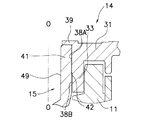
図3に示すように、ハブ14の内周縁に内周側突出部39を設け、それに対してシャフト15の上側端面を当接させることで、ハブ14とシャフト15の軸線方向位置決めを行っている。
【0043】
この実施形態では、ハブ14の円板状部31の内周面及び筒状部33の内周面の軸線方向上側部分が、シャフト15の上側部41の外周面42に対して締結される締結内周面38Aを形成している。つまり、筒状部33の内周面の下側部分38Bの径はシャフト15の上側部41の外径より大きくなっており、内周面下側部分38Bと外周面42との間に微小な間隙が確保されている。以上に述べたように、筒状部33は、前記実施形態とは異なり、その一部のみがシャフト15の外周面42に密着している。
【0044】
3.第3実施形態
この実施形態では、スピンドルモータ1の基本的な構造は前記実施形態と同様である。したがって、ここでは異なる構造の部分のみを説明する。
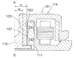
図4に示すように、ハブ114の筒状部133の配置をシャフト115の外周面全体を覆うようにしている。この結果、第1ラジアル軸受部121と第2ラジアル軸受部122は、筒状部133の外周面137によって形成されている。
【0045】
以上に述べたように、第1及び第2ラジアル軸受部121,122がハブ114の筒状部133の外周面において形成されているため、シャフト115の外径が従来と同等であるとすると、第1及び第2ラジアル軸受部121,122の半径r1が従来のラジアル軸受部の半径r2に比べて大きくなっている。したがって、第1及び第2ラジアル軸受部121,122では、周速が増し、発生する動圧が大きくなる。また、発生する動圧に余裕がある場合は、筒状部・スリーブ間の隙間寸法を大きくすることができるので、加工に対する要求精度が緩和され、歩留まりの改善や、加工コストの削減等、モータの低コスト化に寄与することができる。
【0046】
さらに、筒状部133の外周面137とスリーブ111の内周面153は、第1ラジアル軸受部121と第2ラジアル軸受部122を形成する部分がそれぞれ同径であるため、第1ラジアル軸受部121と第2ラジアル軸受部122は同一半径方向位置に配置されている。この結果、第1ラジアル軸受部121と第2ラジアル軸受部122の同軸度が向上している。
【0047】
4.他の実施形態
本発明はかかる上記実施形態に限定されるものではなく、本発明の範囲を逸脱することなく種々の変形乃至修正が可能である。
具体的には、本発明は、前記実施形態に示された動圧軸受、スピンドルモータ又は記録ディスク駆動装置に限定されるものではない。
【0048】
また、潤滑流体としては、潤滑油以外に空気を用いてもよい。
さらに、動圧軸受のラジアル・スラスト軸受部を構成する動圧発生溝の形状や形成位置は、前記実施形態に限定されない。
【0049】
【発明の効果】
請求項1に記載のスピンドルモータでは、記録ディスク装置において、ねじ部材はシャフトのねじ孔に螺合することで、ディスク用クランプをたわませている。このため、ディスク用クランプは記録ディスクをハブとの間で挟みつけている。
【0050】
シャフトにねじ孔を形成することで、ハブの円板状部を薄肉化することができるが、その一方でこの構成によってハブに対するクランプ力がハブの外周部を軸線方向片側に押し付けるように作用している。そのため、クランプによってハブはたわみ変形し、ハブがシャフトに対して嵌合部において傾き、嵌合部の軸線方向先端側で締結が外れるという事態が起こりやすいと考えられる。
【0051】
しかし、この記録ディスク装置では、ハブの筒状部がシャフトに締結されることで、ハブ/シャフト間の接触面積を十分に確保することができ、十分なハブ/シャフト締結強度を得ることができる。したがって、クランプ力が作用したときにハブとシャフトの締結が外れにくくなっている。
請求項2記載のスピンドルモータでは、請求項1において、第1ラジアル軸受部は、ハブの筒状部の外周面において形成されているため、ラジアル軸受部の径が従来に比べて大きくなっている。このため、ラジアル軸受部において周速が増し、発生する動圧が大きくなる。
【0052】
また、ハブとシャフトの締結強度を向上させるために締結区間を単に長く設定するだけでは、ハブ/シャフトの締結部の近傍に設けられたラジアル軸受部の寸法が制限されることになり、その結果軸受剛性等必要な回転支持力を確保することが困難になってしまう。それに対してこのスピンドルモータの構成では、第1ラジアル軸受部はハブの筒状部の外周面において形成されているため、十分な軸受剛性を確保することができる。
【0053】
請求項3に記載のスピンドルモータでは、請求項2において、第2ラジアル軸受部の径は第1ラジアル軸受部の径より小さく従来と同等であるが、軸受機構全体ではラジアル動圧は大きくなっている。
請求項4に記載のスピンドルモータでは、請求項1において、第1及び第2ラジアル軸受部は筒状部の外周面に形成されているため、ラジアル軸受部の径が従来に比べて大きくなっている。このため、ラジアル軸受部において周速が増し、発生する動圧が大きくなる。
【0054】
請求項5に記載のスピンドルモータでは、請求項4において、筒状部の外周面において第1及び第2ラジアル軸受を構成する部分の外径は同一であり、スリーブの2つのラジアル内周面の内径は同一であるため、2つのラジアル軸受部の同軸度が向上している。
請求項6に記載のスピンドルモータでは、請求項1〜5のいずれかにおいて、軸受機構は、シャフトのスラスト面とスリーブのスラスト面との間にスラスト軸受部をさらに有しているため、スラスト軸受部によってスラスト動圧を発生することができる。
【0055】
請求項7に記載の記録ディスク駆動装置では、前述のシャフトとハブの締結強度が向上したスピンドルモータ備えていることによって、記録媒体を安定して回転させることができる。
請求項8に記載の記録ディスク駆動装置では、前述のシャフトとハブの締結強度が向上したスピンドルモータ備えていることによって、記録媒体を安定して回転させることができる。
【図面の簡単な説明】
【図1】本発明の第1実施形態としてのスピンドルモータの縦断面概略図。
【図2】ハブとシャフトの締結部及び第1ラジアル軸受部の縦断面概略図であり、図1の部分拡大図。
【図3】第2実施形態におけるハブとシャフトの締結部及び第1ラジアル軸受部の縦断面概略図。
【図4】第3実施形態としてのスピンドルモータの縦断面概略図。
【図5】一般的なハードディスク装置の概略構成図。
【符号の説明】
1 スピンドルモータ
11 スリーブ
14 ハブ
15 シャフト
21 第1ラジアル軸受部
33 筒状部
38 内周面
41 上側部
42 外周面
49 ねじ孔
88 ディスク用クランプ(クランプ部材)
89 ねじ部材[0001]
BACKGROUND OF THE INVENTION
The present invention relates to a spindle motor, and more particularly to a spindle motor having a rotating member composed of a hub and a shaft fitted in a center hole thereof. The present invention further relates to a recording disk drive apparatus employing the spindle motor.
[0002]
[Prior art]
A recording disk drive device such as a hard disk has a spindle motor for rotational driving arranged concentrically with the recording disk. The spindle motor mainly includes a stationary member having an armature coil, a rotating member having a rotor magnet facing the coil, and a bearing mechanism that rotatably supports the rotating member on the stationary member.
[0003]
As an example of such a spindle motor, a shaft rotation type spindle motor is known. In this spindle motor, the rotating member has a hub and a shaft having one end fitted in the center hole thereof, and the stationary member has a hollow cylindrical sleeve that accommodates the shaft of the rotating member on the inner peripheral side. ing. The hub is generally a disk-shaped member, and a cylindrical portion extending in the axial direction is formed on the outer peripheral edge. A stator coil is provided on the inner peripheral side of the cylindrical portion, and a plurality of recording disks are fixed to the flange portion on the outer peripheral side. The recording disk fixing means includes a clamp member for clamping the recording disk to the end face of the flange and a screw member for fixing the recording disk to the hub. For this reason, the rotation member is formed with a screw hole for screwing the screw member. In addition, as a bearing mechanism, for example, a fluid dynamic pressure bearing is formed between the sleeve and the shaft.
[0004]
[Problems to be solved by the invention]
Due to the recent trend toward downsizing and thinning of devices such as personal computers on which recording disk drive devices are mounted, and the diversification of products used such as application to small devices such as digital cameras of recording disk drive devices, The spindle motor itself that is driven to rotate is also required to be reduced in size and thickness. Therefore, in the spindle motor, the hub, which is a rotating member, is becoming thinner.
[0005]
As the hub becomes thinner, screw holes for fixing the disk clamp to the rotating member cannot be formed in the hub, but are formed in the end face of the shaft. Then, the disk clamp is bent at the central portion by the screw member, so that a bending reaction force is applied to the inner peripheral portion of the recording disk from the outer peripheral portion. Therefore, the outer peripheral portion of the hub is always pushed to the opposite side of the clamp member by the clamping force from the disk clamp.
[0006]
When the clamping force acts in this way, the hub is bent and deformed. Therefore, there is a problem that accuracy (perpendicularity) between the hub and the shaft is deviated and RRO (Repeatable Run-Out) is deteriorated or the fastening between the hub and the shaft is disengaged.
In particular, when the hub is made thinner, the fastening section of the hub / shaft becomes shorter, so that the fastening strength between the shaft and the hub cannot be sufficiently obtained. Therefore, it is conceivable that the above problem becomes more remarkable.
[0007]
Various measures can be considered for the above-described problem of lowering the fastening strength between the shaft and the hub, but each measure includes a problem. For example, in the method of increasing the tightening allowance when the hub / shaft is press-fitted, there is a concern that the load on the hub / shaft (residual stress of fastening, etc.) is increased and plastic deformation occurs, which may deteriorate the rotational accuracy. . Further, in the method of reducing the clamping force, there is a concern that the recording disk is displaced or scattered.
[0008]
SUMMARY OF THE INVENTION An object of the present invention is to provide a spindle motor in which a screw hole for screwing a disk clamp is formed on one end face of a rotary shaft fastened to a center hole of a hub. The problem is to appropriately eliminate the problem of the hub / shaft fastening portion due to the clamping force.
[0009]
[Means for Solving the Problems]
The spindle motor described in claim 1 includes a stationary member, a hub, a shaft, a stator coil, and a rotor magnet. The stationary member has a hollow cylindrical sleeve. The hub includes a disk-shaped part in which a central hole is formed, and a cylindrical part protruding in the axial direction from the inner peripheral edge of the disk-shaped part. The shaft is a member arranged on the inner side in the radial direction of the inner peripheral surface of the sleeve, and one end is fitted to the inner peripheral surface of the cylindrical portion. A screw hole into which a screw member for deflecting the disk clamp is screwed is formed on the end surface of one end of the shaft. The bearing mechanism is a mechanism for rotatably supporting the hub and the shaft with respect to the stationary member. The stator coil is fixed to the stationary member. The rotor magnet is fixed to the hub so as to face the stator coil, and generates a rotating magnetic field in cooperation with the stator coil.
[0010]
In this spindle motor, in the recording disk driving apparatus, the screw member is screwed into the screw hole of the shaft to deflect the disk clamp. For this reason, the disk clamp clamps the recording disk between the hub.
By forming a screw hole in the shaft, the disk-shaped part of the hub can be thinned.However, this configuration allows the clamping force against the hub to press the outer peripheral part of the hub toward one side in the axial direction. ing. For this reason, it is considered that the hub is flexibly deformed by the clamp, the hub is inclined at the fitting portion with respect to the shaft, and the fastening is easily released at the front end side in the axial direction of the fitting portion.
[0011]
However, in this spindle motor, the hub tubular portion is fastened to the shaft, so that a sufficient contact area between the hub and the shaft can be secured, and sufficient hub / shaft fastening strength can be obtained. Therefore, it is difficult for the hub and the shaft to be unfastened when a clamping force is applied.
According to a second aspect of the present invention, in the spindle motor according to the first aspect, the bearing mechanism holds the lubricating fluid between the outer peripheral surface of the cylindrical portion and the radial inner peripheral surface of the sleeve, and induces dynamic pressure in the lubricating fluid. The first radial bearing portion configured by providing the dynamic pressure generating groove is included.
[0012]
In this spindle motor, since the first radial bearing portion is formed on the outer peripheral surface of the cylindrical portion of the hub, the diameter of the radial bearing portion is larger than the conventional one. For this reason, peripheral speed increases in a radial bearing part, and the generated dynamic pressure becomes large.
Also, simply setting the fastening section long in order to improve the fastening strength between the hub and the shaft limits the dimensions of the radial bearing provided near the hub / shaft fastening part. It becomes difficult to secure necessary rotational support force such as bearing rigidity. On the other hand, in this spindle motor configuration, the first radial bearing portion is formed on the outer peripheral surface of the cylindrical portion of the hub, so that sufficient bearing rigidity can be ensured.
[0013]
According to a third aspect of the present invention, in the spindle motor according to the second aspect, the bearing mechanism holds the lubricating oil between a portion of the outer peripheral surface of the shaft that is not covered by the cylindrical portion of the hub and a radial inner peripheral surface of the sleeve. And further includes a second radial bearing portion configured by providing a dynamic pressure generating groove for inducing dynamic pressure in the lubricating fluid.
In this spindle motor, the diameter of the second radial bearing portion is smaller than the diameter of the first radial bearing portion, which is the same as the conventional one, but the radial dynamic pressure is large in the entire bearing mechanism.
[0014]
According to a fourth aspect of the present invention, in the spindle motor according to the first aspect, the bearing mechanism holds the lubricating fluid between the outer peripheral surface of the cylindrical portion and the two radial inner peripheral surfaces of the sleeve, and the dynamic pressure is applied to the lubricating fluid. The first and second radial bearing portions are provided by providing a dynamic pressure generating groove for inducing the above.
In this spindle motor, since the first and second radial bearing portions are formed on the outer peripheral surface of the cylindrical portion, the diameter of the radial bearing portion is larger than the conventional one. For this reason, peripheral speed increases in a radial bearing part, and the generated dynamic pressure becomes large.
[0015]
According to a fifth aspect of the present invention, in the spindle motor according to the fourth aspect, the outer diameters of the portions constituting the first and second radial bearings on the outer peripheral surface of the cylindrical portion are the same, and the two radial inner peripheral surfaces of the sleeve are the same. The inner diameter is the same.
In this spindle motor, the coaxiality of the two radial bearing portions is improved.
According to a sixth aspect of the present invention, in any one of the first to fifth aspects, the bearing mechanism holds the lubricating fluid between the thrust surface of the shaft and the thrust surface of the sleeve, and applies dynamic pressure to the lubricating fluid. It further includes a thrust bearing portion configured by providing an inductive dynamic pressure generating groove.
[0016]
In this spindle motor, the thrust dynamic pressure can be obtained by the thrust bearing portion.
According to a seventh aspect of the present invention, there is provided a recording disk drive device including a housing, the spindle motor according to any one of the first to sixth aspects fixed to the inside of the housing, and information fixed to a disk-shaped portion of the hub. A disc-shaped recording medium capable of recording, and information access means for writing or reading information at a required position of the recording medium are provided.
[0017]
In this recording disk drive apparatus, the recording medium can be stably rotated by providing the spindle motor with the improved fastening strength between the shaft and the hub.
According to an eighth aspect of the present invention, there is provided a recording disk drive device according to the seventh aspect, further comprising: a screw member that is screwed into a screw hole of the shaft; and a disk clamp that is bent by the screw member and clamps the recording medium to the hub. ing.
[0018]
In this recording disk drive apparatus, the recording medium can be stably rotated by providing the spindle motor with the improved fastening strength between the shaft and the hub.
[0019]
DETAILED DESCRIPTION OF THE INVENTION
1. First embodiment
(1) Overall configuration of spindle motor
FIG. 1 is a longitudinal sectional view schematically showing a schematic configuration of a spindle motor 1 as an embodiment of the present invention. The spindle motor 1 is a recording disk driving spindle motor and constitutes a part of a recording disk driving device such as a hard disk.
[0020]
Note that OO shown in FIG. 1 is the rotation axis of the spindle motor 1. In the description of the present embodiment, the vertical direction in FIG. 1 is referred to as the “axis vertical direction” for convenience, but the direction in the actual mounting state of the spindle motor 1 is not limited.
In FIG. 1, the spindle motor 1 mainly includes a stationary member 2, a rotating
[0021]
(2) Stationary member
The stationary member 2 includes a
[0022]
The
[0023]
(3) Rotating member
The rotating
[0024]
The
[0025]
The
[0026]
A
(4) Hub and shaft fastening structure
The
[0027]
A stepped
[0028]
The fastening structure described above will be described in more detail. The
In the fastening structure described above, since the
[0029]
Since the fastening strength between the
(5) Bearing mechanism
The
[0030]
(1) Radial bearing
As shown in FIG. 2, the first radial inner
[0031]
The second radial inner
[0032]
As described above, since the first
[0033]
The radius r2 of the second radial bearing portion 22 is equal to the outer
In addition, simply setting the fastening section to be long in order to improve the fastening strength between the hub and the shaft limits the dimensions because the radial bearing part is provided in the vicinity of the fastening part of the hub / shaft. As a result, it becomes difficult to secure necessary rotational support force such as bearing rigidity in the radial bearing portion. On the other hand, in the configuration of the spindle motor 1, since the first
[0034]
(2) Thrust bearing
The lower inner
[0035]
A thrust flange 46 is formed at the lower end of the
[0036]
The
[0037]
(6) Configuration of hard disk device
Although one embodiment of the spindle motor 1 for driving the recording disk according to the present invention has been described above, a hard disk device as a recording disk driving apparatus having the spindle motor 1 according to the present invention will be described as an example.
FIG. 5 shows a schematic diagram of an internal configuration of a general
[0038]
(7) Clamp structure
As shown in FIG. 1, the
[0039]
The
[0040]
A
[0041]
As described above, since the
[0042]
2. Second embodiment
In this embodiment, the basic structure of the spindle motor 1 is the same as that of the above embodiment. Therefore, only the part of a different structure is demonstrated here.
As shown in FIG. 3, the
[0043]
In this embodiment, the inner circumferential surface of the disk-shaped
[0044]
3. Third embodiment
In this embodiment, the basic structure of the spindle motor 1 is the same as that of the above embodiment. Therefore, only the part of a different structure is demonstrated here.
As shown in FIG. 4, the arrangement of the
[0045]
As described above, since the first and second
[0046]
Furthermore, since the outer
[0047]
4). Other embodiments
The present invention is not limited to the above-described embodiment, and various changes and modifications can be made without departing from the scope of the present invention.
Specifically, the present invention is not limited to the dynamic pressure bearing, the spindle motor, or the recording disk driving device shown in the above embodiment.
[0048]
In addition to the lubricating oil, air may be used as the lubricating fluid.
Furthermore, the shape and the formation position of the dynamic pressure generating groove constituting the radial thrust bearing portion of the dynamic pressure bearing are not limited to the above embodiment.
[0049]
【The invention's effect】
In the spindle motor according to the first aspect, in the recording disk device, the screw member is screwed into the screw hole of the shaft to deflect the disk clamp. For this reason, the disk clamp clamps the recording disk between the hub.
[0050]
By forming a screw hole in the shaft, the disk-shaped part of the hub can be thinned.However, this configuration allows the clamping force against the hub to press the outer peripheral part of the hub toward one side in the axial direction. ing. For this reason, it is considered that the hub is flexibly deformed by the clamp, the hub is inclined at the fitting portion with respect to the shaft, and the fastening is easily released at the front end side in the axial direction of the fitting portion.
[0051]
However, in this recording disk device, the hub tubular portion is fastened to the shaft, so that a sufficient contact area between the hub and the shaft can be secured, and sufficient hub / shaft fastening strength can be obtained. . Therefore, it is difficult for the hub and the shaft to be unfastened when a clamping force is applied.
According to a second aspect of the present invention, in the spindle motor according to the first aspect, since the first radial bearing portion is formed on the outer peripheral surface of the cylindrical portion of the hub, the diameter of the radial bearing portion is larger than that of the conventional one. . For this reason, peripheral speed increases in a radial bearing part, and the generated dynamic pressure becomes large.
[0052]
Also, simply setting the fastening section long in order to improve the fastening strength between the hub and the shaft limits the dimensions of the radial bearing provided near the hub / shaft fastening part. It becomes difficult to secure necessary rotational support force such as bearing rigidity. On the other hand, in this spindle motor configuration, the first radial bearing portion is formed on the outer peripheral surface of the cylindrical portion of the hub, so that sufficient bearing rigidity can be ensured.
[0053]
In the spindle motor according to a third aspect, in the second aspect, the diameter of the second radial bearing portion is smaller than the diameter of the first radial bearing portion, and is equal to the conventional one, but the radial dynamic pressure is increased in the entire bearing mechanism. Yes.
According to a fourth aspect of the present invention, in the spindle motor according to the first aspect, since the first and second radial bearing portions are formed on the outer peripheral surface of the cylindrical portion, the diameter of the radial bearing portion is larger than that of the conventional one. Yes. For this reason, peripheral speed increases in a radial bearing part, and the generated dynamic pressure becomes large.
[0054]
According to a fifth aspect of the present invention, in the spindle motor according to the fourth aspect, the outer diameters of the portions constituting the first and second radial bearings on the outer peripheral surface of the cylindrical portion are the same, and the two radial inner peripheral surfaces of the sleeve are the same. Since the inner diameter is the same, the coaxiality of the two radial bearing portions is improved.
The spindle motor according to
[0055]
In the recording disk drive apparatus according to the seventh aspect, the recording medium can be stably rotated by including the spindle motor having the improved fastening strength between the shaft and the hub.
In the recording disk drive apparatus according to the eighth aspect of the present invention, the recording medium can be stably rotated by including the spindle motor having the improved fastening strength between the shaft and the hub.
[Brief description of the drawings]
FIG. 1 is a schematic longitudinal sectional view of a spindle motor as a first embodiment of the present invention.
2 is a schematic longitudinal sectional view of a fastening portion of a hub and a shaft and a first radial bearing portion, and is a partially enlarged view of FIG. 1;
FIG. 3 is a schematic longitudinal sectional view of a fastening portion between a hub and a shaft and a first radial bearing portion in a second embodiment.
FIG. 4 is a schematic vertical sectional view of a spindle motor as a third embodiment.
FIG. 5 is a schematic configuration diagram of a general hard disk device.
[Explanation of symbols]
1 Spindle motor
11 Sleeve
14 Hub
15 shaft
21 First radial bearing
33 Cylindrical part
38 Inner peripheral surface
41 Upper side
42 outer peripheral surface
49 Screw hole
88 Disc clamp (clamp member)
89 Screw member
Claims (8)
中空円筒状のスリーブを有する静止部材と、
中心孔が形成された円板状部と、前記円板状部の内周縁から軸線方向に突出する筒状部とを有するハブと、
前記スリーブの半径方向内側に配置された部材であって、一端が前記筒状部の内周面に嵌合され、前記一端の端面にはディスク用クランプをたわませるためにねじ部材が螺合するねじ孔が形成されたシャフトと、
前記ハブ及びシャフトを前記静止部材に対して回転自在に支持するための軸受機構と、
前記静止部材に固定されたステータコイルと、
前記ステータコイルに対向するように前記ハブに固定され、前記ステータコイルと協働して回転磁界を発生するためのロータマグネットと、
を備えたスピンドルモータ。A spindle motor used in a recording disk drive device,
A stationary member having a hollow cylindrical sleeve;
A hub having a disk-shaped part in which a central hole is formed, and a cylindrical part protruding in an axial direction from the inner periphery of the disk-shaped part;
A member disposed radially inside the sleeve, one end of which is fitted to the inner peripheral surface of the cylindrical portion, and a screw member is screwed to the end surface of the one end to bend the disk clamp. A shaft formed with a screw hole to be
A bearing mechanism for rotatably supporting the hub and the shaft with respect to the stationary member;
A stator coil fixed to the stationary member;
A rotor magnet fixed to the hub so as to face the stator coil, and generating a rotating magnetic field in cooperation with the stator coil;
With spindle motor.
前記スリーブの前記2つのラジアル内周面の内径は同一である、請求項4に記載のスピンドルモータ。The outer diameters of the portions constituting the first and second radial bearing portions on the outer peripheral surface of the cylindrical portion are the same,
The spindle motor according to claim 4, wherein inner diameters of the two radial inner peripheral surfaces of the sleeve are the same.
前記ハウジングの内部に固定された、請求項1〜6のいずれかに記載の前記スピンドルモータと、
前記ハブの前記円板状部に固定された、情報を記録できる円板状記録媒体と、前記記録媒体の所要の位置に情報を書込又は読み出すための情報アクセス手段と、
を備えた記録ディスク駆動装置。A housing;
The spindle motor according to any one of claims 1 to 6, which is fixed inside the housing;
A disk-shaped recording medium fixed to the disk-shaped portion of the hub and capable of recording information; and an information access means for writing or reading information at a required position of the recording medium;
A recording disk drive device comprising:
前記ねじ部材によってたわまされ、前記記録媒体を前記ハブにクランプするディスク用クランプと、
をさらに備えている、請求項7に記載の記録ディスク駆動装置。A screw member screwed into the screw hole of the shaft;
A disk clamp that is bent by the screw member and clamps the recording medium to the hub;
The recording disk drive device according to claim 7, further comprising:
Priority Applications (1)
| Application Number | Priority Date | Filing Date | Title |
|---|---|---|---|
| JP2002025984A JP3786355B2 (en) | 2002-02-01 | 2002-02-01 | Spindle motor and recording disk drive device |
Applications Claiming Priority (1)
| Application Number | Priority Date | Filing Date | Title |
|---|---|---|---|
| JP2002025984A JP3786355B2 (en) | 2002-02-01 | 2002-02-01 | Spindle motor and recording disk drive device |
Publications (2)
| Publication Number | Publication Date |
|---|---|
| JP2003235203A JP2003235203A (en) | 2003-08-22 |
| JP3786355B2 true JP3786355B2 (en) | 2006-06-14 |
Family
ID=27773328
Family Applications (1)
| Application Number | Title | Priority Date | Filing Date |
|---|---|---|---|
| JP2002025984A Expired - Fee Related JP3786355B2 (en) | 2002-02-01 | 2002-02-01 | Spindle motor and recording disk drive device |
Country Status (1)
| Country | Link |
|---|---|
| JP (1) | JP3786355B2 (en) |
Cited By (1)
| Publication number | Priority date | Publication date | Assignee | Title |
|---|---|---|---|---|
| US7371010B2 (en) | 2004-12-28 | 2008-05-13 | Matsushita Electric Industrial, Co., Ltd. | Hydrodynamic bearing device and compact motor including hydrodynamic bearing device |
Families Citing this family (1)
| Publication number | Priority date | Publication date | Assignee | Title |
|---|---|---|---|---|
| JP2005192292A (en) * | 2003-12-25 | 2005-07-14 | Matsushita Electric Ind Co Ltd | Spindle motor |
-
2002
- 2002-02-01 JP JP2002025984A patent/JP3786355B2/en not_active Expired - Fee Related
Cited By (1)
| Publication number | Priority date | Publication date | Assignee | Title |
|---|---|---|---|---|
| US7371010B2 (en) | 2004-12-28 | 2008-05-13 | Matsushita Electric Industrial, Co., Ltd. | Hydrodynamic bearing device and compact motor including hydrodynamic bearing device |
Also Published As
| Publication number | Publication date |
|---|---|
| JP2003235203A (en) | 2003-08-22 |
Similar Documents
| Publication | Publication Date | Title |
|---|---|---|
| JP3878861B2 (en) | Spindle motor and recording disk drive | |
| JP3536022B2 (en) | Pivot bearing device | |
| US6563243B2 (en) | Spindle motor | |
| US5517374A (en) | Magnetic disk drive apparatus having disk clamp attachable using a single fastener | |
| US20120212092A1 (en) | Rotating device having a rotor and a stator | |
| JP2008043045A (en) | Brushless motor and disk drive unit | |
| JP3984451B2 (en) | Motor and disk device | |
| US7262935B2 (en) | Top cover attached single plate fluid dynamic bearing motor | |
| JP2005531276A (en) | Rotor limiter for hydrodynamic bearing motor | |
| JP3786355B2 (en) | Spindle motor and recording disk drive device | |
| JP2006112505A (en) | Bearing mechanism, carriage assembly, and magnetic disk drive | |
| US7511398B2 (en) | Motor and recording disk driving device | |
| EP1134875A1 (en) | A spindle motor for disk driving device with fluid bearing | |
| JP3110389U (en) | Fluid dynamic pressure bearing device for motor, spindle motor equipped with fluid dynamic pressure bearing device, and recording disk drive device | |
| US9196292B1 (en) | Rotary spindle having a disk clamp bottom land facing and in contact with a shaft top land | |
| JP3974384B2 (en) | Motor and disk device | |
| JP2004364398A (en) | Spindle motor and recording disk drive | |
| JP4801997B2 (en) | Disk unit | |
| JP2000322820A (en) | Disc drive motor | |
| US8106560B2 (en) | Stiffness of brushless motor including stator core and disk drive | |
| KR101153602B1 (en) | Stopper ring for spindle motor and motor with same | |
| JP2016123209A (en) | motor | |
| JP2000149395A (en) | Magnetic disk drive | |
| US20060152848A1 (en) | Recording disk driving motor and recording disk driving apparatus having the same | |
| JPH05135515A (en) | Magnetic disk device |
Legal Events
| Date | Code | Title | Description |
|---|---|---|---|
| A621 | Written request for application examination |
Free format text: JAPANESE INTERMEDIATE CODE: A621 Effective date: 20040401 |
|
| RD05 | Notification of revocation of power of attorney |
Free format text: JAPANESE INTERMEDIATE CODE: A7425 Effective date: 20050808 |
|
| A977 | Report on retrieval |
Free format text: JAPANESE INTERMEDIATE CODE: A971007 Effective date: 20060214 |
|
| TRDD | Decision of grant or rejection written | ||
| A01 | Written decision to grant a patent or to grant a registration (utility model) |
Free format text: JAPANESE INTERMEDIATE CODE: A01 Effective date: 20060314 |
|
| A61 | First payment of annual fees (during grant procedure) |
Free format text: JAPANESE INTERMEDIATE CODE: A61 Effective date: 20060316 |
|
| R150 | Certificate of patent or registration of utility model |
Free format text: JAPANESE INTERMEDIATE CODE: R150 |
|
| LAPS | Cancellation because of no payment of annual fees |