JP3785043B2 - Equipment for sterilizing chambers - Google Patents
Equipment for sterilizing chambers Download PDFInfo
- Publication number
- JP3785043B2 JP3785043B2 JP2000596978A JP2000596978A JP3785043B2 JP 3785043 B2 JP3785043 B2 JP 3785043B2 JP 2000596978 A JP2000596978 A JP 2000596978A JP 2000596978 A JP2000596978 A JP 2000596978A JP 3785043 B2 JP3785043 B2 JP 3785043B2
- Authority
- JP
- Japan
- Prior art keywords
- liquid
- processing chamber
- switching member
- chamber
- pressure
- Prior art date
- Legal status (The legal status is an assumption and is not a legal conclusion. Google has not performed a legal analysis and makes no representation as to the accuracy of the status listed.)
- Expired - Fee Related
Links
Images


Classifications
-
- B—PERFORMING OPERATIONS; TRANSPORTING
- B08—CLEANING
- B08B—CLEANING IN GENERAL; PREVENTION OF FOULING IN GENERAL
- B08B9/00—Cleaning hollow articles by methods or apparatus specially adapted thereto
- B08B9/02—Cleaning pipes or tubes or systems of pipes or tubes
- B08B9/027—Cleaning the internal surfaces; Removal of blockages
- B08B9/032—Cleaning the internal surfaces; Removal of blockages by the mechanical action of a moving fluid, e.g. by flushing
- B08B9/0321—Cleaning the internal surfaces; Removal of blockages by the mechanical action of a moving fluid, e.g. by flushing using pressurised, pulsating or purging fluid
-
- A—HUMAN NECESSITIES
- A61—MEDICAL OR VETERINARY SCIENCE; HYGIENE
- A61B—DIAGNOSIS; SURGERY; IDENTIFICATION
- A61B1/00—Instruments for performing medical examinations of the interior of cavities or tubes of the body by visual or photographical inspection, e.g. endoscopes; Illuminating arrangements therefor
- A61B1/12—Instruments for performing medical examinations of the interior of cavities or tubes of the body by visual or photographical inspection, e.g. endoscopes; Illuminating arrangements therefor with cooling or rinsing arrangements
- A61B1/121—Instruments for performing medical examinations of the interior of cavities or tubes of the body by visual or photographical inspection, e.g. endoscopes; Illuminating arrangements therefor with cooling or rinsing arrangements provided with means for cleaning post-use
- A61B1/123—Instruments for performing medical examinations of the interior of cavities or tubes of the body by visual or photographical inspection, e.g. endoscopes; Illuminating arrangements therefor with cooling or rinsing arrangements provided with means for cleaning post-use using washing machines
-
- A—HUMAN NECESSITIES
- A61—MEDICAL OR VETERINARY SCIENCE; HYGIENE
- A61L—METHODS OR APPARATUS FOR STERILISING MATERIALS OR OBJECTS IN GENERAL; DISINFECTION, STERILISATION OR DEODORISATION OF AIR; CHEMICAL ASPECTS OF BANDAGES, DRESSINGS, ABSORBENT PADS OR SURGICAL ARTICLES; MATERIALS FOR BANDAGES, DRESSINGS, ABSORBENT PADS OR SURGICAL ARTICLES
- A61L2/00—Methods or apparatus for disinfecting or sterilising materials or objects other than foodstuffs or contact lenses; Accessories therefor
- A61L2/02—Methods or apparatus for disinfecting or sterilising materials or objects other than foodstuffs or contact lenses; Accessories therefor using physical phenomena
-
- A—HUMAN NECESSITIES
- A61—MEDICAL OR VETERINARY SCIENCE; HYGIENE
- A61L—METHODS OR APPARATUS FOR STERILISING MATERIALS OR OBJECTS IN GENERAL; DISINFECTION, STERILISATION OR DEODORISATION OF AIR; CHEMICAL ASPECTS OF BANDAGES, DRESSINGS, ABSORBENT PADS OR SURGICAL ARTICLES; MATERIALS FOR BANDAGES, DRESSINGS, ABSORBENT PADS OR SURGICAL ARTICLES
- A61L2/00—Methods or apparatus for disinfecting or sterilising materials or objects other than foodstuffs or contact lenses; Accessories therefor
- A61L2/16—Methods or apparatus for disinfecting or sterilising materials or objects other than foodstuffs or contact lenses; Accessories therefor using chemical substances
- A61L2/18—Liquid substances or solutions comprising solids or dissolved gases
-
- B—PERFORMING OPERATIONS; TRANSPORTING
- B08—CLEANING
- B08B—CLEANING IN GENERAL; PREVENTION OF FOULING IN GENERAL
- B08B3/00—Cleaning by methods involving the use or presence of liquid or steam
- B08B3/04—Cleaning involving contact with liquid
- B08B3/10—Cleaning involving contact with liquid with additional treatment of the liquid or of the object being cleaned, e.g. by heat, by electricity or by vibration
- B08B3/12—Cleaning involving contact with liquid with additional treatment of the liquid or of the object being cleaned, e.g. by heat, by electricity or by vibration by sonic or ultrasonic vibrations
-
- B—PERFORMING OPERATIONS; TRANSPORTING
- B08—CLEANING
- B08B—CLEANING IN GENERAL; PREVENTION OF FOULING IN GENERAL
- B08B9/00—Cleaning hollow articles by methods or apparatus specially adapted thereto
-
- A—HUMAN NECESSITIES
- A61—MEDICAL OR VETERINARY SCIENCE; HYGIENE
- A61L—METHODS OR APPARATUS FOR STERILISING MATERIALS OR OBJECTS IN GENERAL; DISINFECTION, STERILISATION OR DEODORISATION OF AIR; CHEMICAL ASPECTS OF BANDAGES, DRESSINGS, ABSORBENT PADS OR SURGICAL ARTICLES; MATERIALS FOR BANDAGES, DRESSINGS, ABSORBENT PADS OR SURGICAL ARTICLES
- A61L2202/00—Aspects relating to methods or apparatus for disinfecting or sterilising materials or objects
- A61L2202/10—Apparatus features
- A61L2202/11—Apparatus for generating biocidal substances, e.g. vaporisers, UV lamps
-
- A—HUMAN NECESSITIES
- A61—MEDICAL OR VETERINARY SCIENCE; HYGIENE
- A61L—METHODS OR APPARATUS FOR STERILISING MATERIALS OR OBJECTS IN GENERAL; DISINFECTION, STERILISATION OR DEODORISATION OF AIR; CHEMICAL ASPECTS OF BANDAGES, DRESSINGS, ABSORBENT PADS OR SURGICAL ARTICLES; MATERIALS FOR BANDAGES, DRESSINGS, ABSORBENT PADS OR SURGICAL ARTICLES
- A61L2202/00—Aspects relating to methods or apparatus for disinfecting or sterilising materials or objects
- A61L2202/20—Targets to be treated
- A61L2202/23—Containers, e.g. vials, bottles, syringes, mail
Abstract
Description
【0001】
本発明は、室のための殺菌液体の供給源と、この殺菌液体の内部に圧力、振幅及び周波数の変動を前記変動の勾配で導入しこの液体の内部にキャビテーション(空洞現象)を発生させる手段とを具備する室の内部を洗浄し殺菌する装置に関する。
【0002】
キャビテーションは表面の侵食、騒音、及び液体との接触の損失のような水力学上の装置において良く知られている好ましくない作用に加えて、ある種の用途においては有用である他の特徴を有していることがわかっている。
【0003】
これらの特徴の第1は機械的なものでありキャビテーション状態における毛細管現象の限界を超えることができるようにする。この特性はしたがってさもなければ到達できないような領域を処理する時に利用することができる。
【0004】
この破壊的な特性は、一時的ではあるものの大きな熱波を開発することにより良識的に利用することができる。このことは付随する酸化反応についても当てはまることである。これは微生物への負圧によって生じた蒸気の泡の発熱性の内部破裂がそのエネルギーを非常に短い時間に非常に小さい表面積上で解放し、非常に高い温度を一時的に形成するからである。
【0005】
これはしたがって、機械的、熱的及び化学的作用の結合であり、これによりこれらの1つについてまた同時に洗浄及び/又は殺菌剤の使用を改善しまたその効率を増進できるようにする。1つの物質の他の物質との分離が大きく向上され同一の液体の薬剤による簡単なすすぎや長時間の浸漬によっては得ることのできないキャビテーション状態での空洞又は浸漬された本体の殺菌を可能にする。
【0006】
規定の液体中で公知の熱力学上の条件が満足された時にキャビテーションが出現するので、閉鎖され液体で充たされた室の内部が、その大きさと形式が適当である圧力変動の作用を受けこの液体の中に特定温度のキャビテーションを発生させるのに十分となる。このキャビテーションの効果は液体自体に、容器の壁に、又は液体に浸漬された本体に、もたらされる。
【0007】
圧力信号の要求はしかし極めて特殊なものであり所望の圧力の高さと周波数の機械的な選択によってのみ得ることは困難である。
【0008】
洗浄と殺菌のためのキャビテーションの利用は医療分野において又は医療もしくは準医療用器具を洗浄し殺菌する場合において多くの用途の主題となっている。超音波振動とキャビテーションとの組合せもまた洗浄と殺菌に対して提案されている。例えば液体内部の流速を変えることにより発生されたキャビテーションによって液体中のビールスを不活性化させる方法に関するドイツ特許第3903648号が参照される。この方法は高圧ポンプとその下流側に配置された均質化弁とを用いて実施される。
【0009】
ヨーロッパ特許第0,078,614号においては、コンタクトレンズが、超音波振動でキャビテーションが発生された塩類の溶液の中で洗浄され殺菌される。
【0010】
超音波とキャビテーションとを組合せる他の洗浄及び殺菌方法はヨーロッパ特許第0,595,783号と米国特許第4,193,818号に記載されている。超音波と組合されたキャビテーションは洗浄された表面を腐食する欠点を有している。
【0011】
ヨーロッパ特許第0,299,919号には、キャビテーションを歯の活力を奪うのに用い、末端片が歯の歯髄室に接近できるように形成された開口に液密状に取付けられる方法が提案されている。この末端片は供給ポンプに接続された液体噴射器と吸引ポンプに接続された放出導管とを具備している。吸引ポンプは液体中に泡を発生し、圧力ポンプが内部破裂を生じさせキャビテーションを生成させるようにする。
【0012】
上記の装置に対する改良がヨーロッパ特許第0,521,119号に提案されここでは水−噴流ポンプが、ジャベル水で充たされた歯の歯髄室のオリフィスに液密状に取付けることのできる調節可能な末端片の中に配設される。この水−噴流ポンプの入口はピストンポンプの出口導管に接続され、その出口は放出導管に接続され、その吸入導管は歯髄室に開口している。ポンプの各サイクルで、一定容量の液体の往復運動が交互の圧縮と吸入とにより放出導管に生じ、ポンプを水−噴流ポンプを介して放出導管に接続する導管では歯髄室の液体に交互の負圧と過圧を発生しそれによりキャビテーションを発生させる。
【0013】
活力を奪うためのこれら装置の第1は2つのポンプを必要とし処理液体自体からなる液体の高度の消費を伴うものである。これら活力を奪う装置の第2は、あたかも水−噴流ポンプを駆動するモータのような単動ピストンポンプを用い、歯髄室内に圧力の変動を発生させる。この目的に用いられるピストンポンプは、単動弁の閉鎖から始まり正弦波の勾配に到達するまで増大する正弦波状の圧力を発生する。この勾配はキャビテーションの発生に有用であるにすぎず、またこの勾配はできるだけ急勾配としできるだけ急激の変化を生じるようにしなければならない。正弦波状の変動がそれ自体では所望のキャビテーションを生じるのに十分でなかったならば動きかつ共振器として作動する液体を介して歯髄室の圧力に作用し水−噴流ポンプを介して所要の急激な圧力変動を発生させるようにする。
【0014】
本発明の目的は水−噴流ポンプによらず、すなわち積極的な圧力発生装置なしで、直接的に同じ効果が達成できるようにすることである。
【0015】
このため、本発明の主題は請求項1に記載の室の内部を洗浄し殺菌する装置である。
【0016】
切換え部材を用いることにより、この切換え部材を殺菌室に接続する液柱が2つの規定された圧力と連通するようにされこの2つの圧力の間の差が所望の強さに対応するようにし、それにより変動の勾配が非常に大きくなり導管内の水頭の損失のみがこの2つの圧力の強さが一定であるためこの勾配に影響を与えるようにすることが可能となる。さらに、2つの圧力の強さの一方の圧力のみが人工的に発生され最高圧力に相当する他方の圧力の強さは単に大気圧であるようにしなければならない。この装置はしたがって戻りばねによりその2つの位置の一方の位置に変わることなく戻されるようになるばねピストンとして作用する。本発明の場合は、このばねは大気圧力によって形成される。
【0017】
添付の図面は本発明の主題を形成する洗浄及び殺菌装置の実施態様を略図式に例示として示すものである。
【0018】
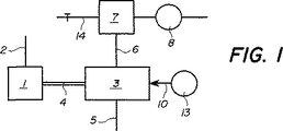
その作動原理が図1によって示されている洗浄装置は一方において処理液体2の較正された供給源に接続され他方において分配又は切換え部材3に導管4を介して接続された処理室1を具備している。この切換え部材3の第1の入口5は大気圧に連通しまた第2の入口6は真空ポンプ8と調節可能な補助空気入口14とに接続された低圧力源7に連通している。図2にさらに詳細に示されているこの切換え部材3は円筒状本体からなりこの円筒状本体を貫通して軸方向の通絡が延び、該通路に導管5と6が横方向に開口しておりまた該通路の軸方向端部はこの切換え部材を処理室1に接続する導管4に連通している。
【0019】
分配回転子10がこの軸方向通路に取付けられ、またブロック9の一端で回転子の周りに取付けられ蓋によって所定位置に保持されたOリングシール11が軸方向通路の漏れ防止を保証する。ブロック9から突出する分配回転子10の端部はモータ13の駆動シャフトと一体である。導管4に連通する回転子10の端部は、2つの細溝10bと10cが設けられた軸方向通路10aを有し、2つの細溝10bと10cは軸方向通路10aを導管5と大気圧に、また導管6と真空源に、それぞれ周期的に連通させるようになっている。
【0020】
上記の装置によって生じる周期的な工程の第1の段階は処理室1の中の圧力を急激に下降させ処理室1を充たす処理液の蒸気圧力を下げ、処理室を低圧源7に連通させることを含み、回転子10は次に図2に示される角度位置に置かれる。液体の温度と性質とその純度とは必要とする変動の度合と勾配に影響を与える。それぞれの不純物又は機械的な不連続性は与えられた液体に対して潜在的な泡の障害を生じる。本発明の場合はこの勾配が非常に急であり、従来技術の方式におけるようにポンプの正弦波状の運動の干渉がないのに比べて、導管を介する水頭の損失だけが室に負圧を形成するのに考慮されることが注目される。
【0021】
この工程の第2の段階は、室1に大気圧を再度形成することによって第1の段階で生じた蒸気の泡を内部破裂させることにあり、この大気圧の再度の形成は細溝10bを導管5と大気圧とに連通させる回転子10の回転によって得られる。導管4に吸込まれた液体は室に戻り、前に形成された全ての蒸気泡の同時の内部破裂を開始させる僅かの瞬間的な過圧を発生させる。
【0022】
状態の変化の最大の効果はダイヤフラムポンプ8によって低圧源7に保持されている真空に比例する。真空の度合はしかし調節可能な補助空気入口14による所望動力の関数として調製することができる。
【0023】
装置は処理室を介して、較正された液体2の供給で充填され、平均圧力はこの作動様式では負圧である。液柱の往復作用は実際に正しく導入されるよう用意された導管にのみ与えられまた液体の再生は装置を開放したときでも望ましい。
【0024】
回転子10を駆動するモータ13の回転速度は用いられる液体の性質、その温度及び選択された負圧の関数として調節される。導管4を通る処理室1から取出された混合物の状態(溶解されたガスの割合)は1つの役割りを演じ特に溶解の作用中の適合性を必要とする。
【0025】
処理室1を切替え部材3に接続する導管4の寸法と剛性はサイクルの頻度に関係している。ポリウレタンで作られ内径が2mmで1mmの壁と320mmの長さを有する導管が用いられた液体の大部分に関し15から25Hzのオーダーの周波数で良好な結果が得られた。この大きさは数cm3 までの容量の良好なキャビテーション状態を発生させるのに適している。新鮮な液体のための入口の制限の寸法は管路の良好な充填と本来的な容量の損失との間の歩み寄りを必要とし、ステンレス鋼で作られ0.3mmの内径と15mmの長さのチューブが良好の結果が得られた。作動出力は用いられる液体に依存し10ml/分のオーダーである。
【0026】
空気入口14の較正は用いられるダイヤフラムポンプに依存する。調製弁が最良の使用の容易さを提供する。ダイヤフラムポンプは低圧源7で空気入口14が完全に閉じられた時作動状態で少なくとも−0.9.105 Paの真空に達することができるようにしなければならない。この圧力はそれ自体が液体の蒸気圧力より高いことが注目されるべきである。しかし液性4によって、動的状態で低圧源7における負の圧力の値よりも低い最高値に達することができる。
【0027】
図3から5は上記の装置の使用例を示し、この装置は歯の活力を奪うのに用いられている。この特定の使用において、処理室1は活力が奪われる歯Dの歯髄室Pによって形成され、内視鏡15が歯Dの歯髄室Pを、一方において処理液の供給源2に接続し、他方において歯髄室Pを切換え部材3に接続する導管4に接続するようになっている。
【0028】
図5に示されるように、内視鏡15は、それ自体が歯Dに形成された開口に取付けられ歯Dの歯髄室Pに接近できるようにする可撓性の連結要素15bに漏れがないように取付けられた接合要素15aを具備している。可撓連結要素15bの周りに形成されたセメント(接合剤)Cのシールが処理室の液密性を保証する作用をする。この使用は活力のある又は活力のない根の抜髄(歯髄を除去する)に真実の利点をもたらす。従来普通に用いてられている次亜塩素酸ナトリウムの作用は腐食性の液体と歯の神経との間の増大された接触面によってより効果的になり、手でも接近できない非常に小さな引込んだ所や隅部に到達できるようになる。キャビテーションの殺菌効果は干渉の効力を付加し残留している微生物をなくする。さらにまた、この作用は非侵略的であり、それにより外傷性症状が負わされるのを減少する。
【0029】
補充連結要素の使用はより人間工学的で有利には可撓性の連結部をもたらす。これはまた末端片15を取外しセメントCを破壊することを要しないで所定位置に戻すことができるようにする利点を有している。
【0030】
図6はソフトコンタクトレンズを湿らせ殺菌するための本発明の他の有利な使用を示す。この図ではソフトコンタクトレンズLが浸漬される処理室1′の内部に接近できる開口に内視鏡15が固定されていることが分かる。処理室1′は例えば差込み型の留め金によって液密状に相互に接合された2つの部分1a′,1b′で構成されている。この親水性のコンタクトレンズは10分のオーダーの時間で湿潤される液体の容量のキャビテーションを発生させることにより全ての微生物をなくすことができる。同じ特定の殺菌製品を一晩中浸漬してもそれ自体によりこの使用からバクテリアの浄化を達成することはできない。
【0031】
図7は、圧熱滅菌されない内視鏡装置のための、また特に生検鉗子のための通路が設けられている内視鏡装置のための、本発明の装置の他の有利な使用を示している。このような装置は実際上この装置が各使用後に受ける殺菌液体に単に浸漬するだけでは殺菌されることはない。これら装置が没入される殺菌薬剤のキャビテーションと循環が装置を効果的に殺菌し装置を短時間後に再使用できるようにする。
【0032】
内視鏡Eの活動端部が嵌合されている処理室1″は、その端部がOリングシール19,20がそれぞれ設けられている底部で2つの環状溝17,18にそれぞれ係合されているチューブ16からなっている。環状溝17は閉鎖部材21に形成されており、これに対し溝18は内視鏡Eの円錐台形部分23に当接して係合するようになっている閉鎖リング22に形成されている。接合片24がチューブ16の壁を貫通しチューブの内部を図1のキャビテーション発生器に接続するのに用いられる。処理室として作用するチューブ16の内部はこのような通路が存在する時に内視鏡の生検鉗子のための接近通路25を介して処理液体で充たされる。このほかに、チューブの内部はチューブ16の壁を通して直接供給することができる。
【0033】
図6に記載されたものと非常によく似ている他の使用はカテーテルを取外すことなく行うことのできるカテーテルの閉鎖の開放に適用することができる。このため、図8に示されるように、内視鏡15が排液のために意図されたカテーテル26の端部に固定される。キャビテーションが、固まりが通路を封鎖する限り発生し、凝結防止液をカテーテル26の導管を塞ぐ血液の固まりの接触面まで導入する。キャビテーションは新鮮な血液の流れの吸引が再現すると好結果の作動のため自然発生的に停止し、その後に排液作用が末端部15の所定位置で元どおりに行われる。
【0034】
上記装置の使用はまた動脈又は静脈の開放に拡大される。しかし、この場合はこれら血管の壁が堅固でなかったならば、これら血管の破裂を防止する手段が必要であり、キャビテーションを生じさせるために圧力を大気圧以下に下げなければならない。
【0035】
もちろん、真空源7と切換え部材の寸法は処理室に必要な容量に適合するようにする必要がある。
【0036】
上記の用途と異なる用途と同じ洗浄及び殺菌装置の使用とはもちろん予想できるものである。
【図面の簡単な説明】
【図1】 装置の原理を示すブロック図である。
【図2】 図1の細部の断面図である。
【図3】 図1の他の細部の正面図である。
【図4】 図3のルール線に沿った図である。
【図5】 第1の用途にしたがう、断面で示された歯に取付けられた図3の細部を示す図である。
【図6】 コンタクトレンズのための洗浄及び殺菌室に取付けられた図3の細部を示す図である。
【図7】 一部分が本発明の装置の殺菌室に配置され、特にこの用途に適合するようにしている内視鏡の正面図である。
【図8】 本発明の他の用途の一部を切断して示す正面図である。[0001]
The present invention provides a source of sterilizing liquid for a chamber and means for introducing cavitation inside the liquid by introducing pressure, amplitude and frequency fluctuations into the sterilizing liquid with a gradient of the fluctuations. And an apparatus for cleaning and sterilizing the inside of the chamber.
[0002]
Cavitation has other features that are useful in certain applications in addition to the unfavorable effects well known in hydraulic devices such as surface erosion, noise, and loss of contact with liquids. I know that
[0003]
The first of these features is mechanical, allowing the capillarity limit in the cavitation state to be exceeded. This property can therefore be exploited when processing regions that would otherwise be unreachable.
[0004]
This destructive property can be exploited sensible by developing large, but temporary, heat waves. This is also true for the accompanying oxidation reaction. This is because the exothermic internal burst of vapor bubbles caused by negative pressure on the microorganisms releases its energy over a very small surface area in a very short time, temporarily forming a very high temperature .
[0005]
This is therefore a combination of mechanical, thermal and chemical action, which makes it possible to improve the use and efficiency of cleaning and / or disinfecting agents for one of these simultaneously. Separation of one substance from another is greatly improved, enabling sterilization of cavitations or immersed bodies that cannot be obtained by simple rinsing or prolonged immersion with the same liquid drug .
[0006]
Cavitation occurs when a known thermodynamic condition is met in a specified liquid, so that the interior of a closed and liquid-filled chamber is subject to pressure fluctuations of appropriate size and type. It is sufficient to generate cavitation at a specific temperature in this liquid. This cavitation effect is effected on the liquid itself, on the wall of the container, or on the body immersed in the liquid.
[0007]
The pressure signal requirements are however very specific and are difficult to obtain only by mechanical selection of the desired pressure height and frequency.
[0008]
The use of cavitation for cleaning and sterilization has been the subject of many applications in the medical field or when cleaning and sterilizing medical or semi-medical devices. A combination of ultrasonic vibration and cavitation has also been proposed for cleaning and sterilization. Reference is made, for example, to German Patent No. 3903648, which relates to a method for inactivating viruses in a liquid by cavitation generated by changing the flow velocity inside the liquid. This method is carried out using a high-pressure pump and a homogenization valve arranged downstream thereof.
[0009]
In European Patent No. 0,078,614, contact lenses are cleaned and sterilized in a salt solution in which cavitation is generated by ultrasonic vibration.
[0010]
Other cleaning and sterilization methods that combine ultrasound and cavitation are described in EP 0,595,783 and US Pat. No. 4,193,818. Cavitation combined with ultrasound has the disadvantage of corroding the cleaned surface.
[0011]
European Patent No. 0,299,919 proposes a method in which cavitation is used to take away the vitality of a tooth and the end piece is attached in a liquid-tight manner to an opening formed to allow access to the dental pulp chamber of the tooth. ing. The end piece comprises a liquid ejector connected to the supply pump and a discharge conduit connected to the suction pump. The suction pump generates bubbles in the liquid, causing the pressure pump to cause internal rupture and create cavitation.
[0012]
An improvement to the above device is proposed in European Patent No. 0,521,119 where a water-jet pump is adjustable which can be liquid-tightly attached to the orifice of a dental pulp chamber of a tooth filled with javel water. Disposed in the end piece. The inlet of the water-jet pump is connected to the outlet conduit of the piston pump, the outlet is connected to the discharge conduit, and the suction conduit opens into the pulp chamber. In each cycle of the pump, a reciprocating movement of a constant volume of liquid occurs in the discharge conduit by alternating compression and inhalation, and in the conduit connecting the pump to the discharge conduit via a water-jet pump, alternating negative pressure is present in the pulp chamber fluid. Pressure and overpressure are generated, thereby generating cavitation.
[0013]
The first of these devices for depriving vitality requires two pumps and involves a high consumption of liquid consisting of the processing liquid itself. The second of these energy-reducing devices uses a single-acting piston pump, such as a motor that drives a water-jet pump, to generate pressure fluctuations in the dental pulp chamber. Piston pumps used for this purpose generate a sinusoidal pressure starting from the closing of a single-acting valve and increasing until a sinusoidal gradient is reached. This gradient is only useful for the occurrence of cavitation, and this gradient must be as steep as possible to produce as steep changes as possible. If sinusoidal fluctuations were not sufficient to produce the desired cavitation on their own, they would act on the pulp chamber pressure via a fluid that acted and acted as a resonator, and the required abruptness via a water-jet pump. Try to generate pressure fluctuations.
[0014]
The object of the present invention is to make it possible to achieve the same effect directly without a water-jet pump, i.e. without an active pressure generator.
[0015]
For this purpose, the subject of the present invention is a device for cleaning and sterilizing the interior of a chamber according to claim 1.
[0016]
By using a switching member, the liquid column connecting the switching member to the sterilization chamber is brought into communication with two defined pressures so that the difference between the two pressures corresponds to the desired strength; This makes the gradient of variation very large, so that only the loss of the head in the conduit can affect this gradient because the strength of the two pressures is constant. Furthermore, only one of the two pressure strengths must be artificially generated and the other pressure strength corresponding to the maximum pressure must simply be atmospheric pressure. This device thus acts as a spring piston that is returned by the return spring without changing to one of its two positions. In the case of the present invention, this spring is formed by atmospheric pressure.
[0017]
The accompanying drawings schematically illustrate, by way of example, embodiments of a cleaning and sterilizing apparatus that form the subject of the present invention.
[0018]
The cleaning device, whose principle of operation is illustrated by FIG. 1, comprises a processing chamber 1 connected on the one hand to a calibrated source of processing
[0019]
A distributing
[0020]
The first stage of the periodic process generated by the above apparatus is to cause the pressure in the processing chamber 1 to drop sharply to lower the vapor pressure of the processing liquid filling the processing chamber 1 and to connect the processing chamber to the low pressure source 7. The
[0021]
The second stage of this process is to rupture the vapor bubbles generated in the first stage by re-creating the atmospheric pressure in the chamber 1, and this re-formation of the atmospheric pressure causes the
[0022]
The maximum effect of the change in state is proportional to the vacuum held in the low pressure source 7 by the diaphragm pump 8. The degree of vacuum can, however, be adjusted as a function of the desired power through the adjustable
[0023]
The apparatus is filled with a calibrated supply of
[0024]
The rotational speed of the
[0025]
The size and stiffness of the
[0026]
Calibration of the
[0027]
Figures 3 to 5 show an example of the use of the above device, which is used to deprive teeth of vitality. In this particular use, the treatment chamber 1 is formed by the pulp chamber P of the tooth D whose vitality is deprived, and the
[0028]
As shown in FIG. 5, the
[0029]
The use of a supplemental coupling element results in a more ergonomic and advantageously flexible coupling. This also has the advantage that the
[0030]
FIG. 6 shows another advantageous use of the invention for moistening and sterilizing soft contact lenses. In this figure, it can be seen that the
[0031]
FIG. 7 shows another advantageous use of the device according to the invention for an endoscopic device which is not autoclaved and in particular for an endoscopic device provided with a passage for biopsy forceps. ing. Such devices are practically not sterilized by simply immersing them in the sterilizing liquid that they receive after each use. The cavitation and circulation of the sterilizing agent into which these devices are immersed effectively sterilizes the devices so that they can be reused after a short time.
[0032]
The processing chamber 1 ″ in which the active end portion of the endoscope E is fitted is engaged with the two
[0033]
Another use very similar to that described in FIG. 6 can be applied to opening the catheter closure that can be done without removing the catheter. For this reason, as shown in FIG. 8, the
[0034]
The use of the device is also extended to open arteries or veins. However, in this case, if the walls of these blood vessels were not firm, a means to prevent the rupture of these blood vessels was necessary, and the pressure had to be reduced below atmospheric pressure in order to cause cavitation.
[0035]
Of course, the dimensions of the vacuum source 7 and the switching member must be adapted to the capacity required for the processing chamber.
[0036]
Of course, the use of the same cleaning and sterilization apparatus as the use different from the above use can be expected.
[Brief description of the drawings]
FIG. 1 is a block diagram illustrating the principle of an apparatus.
2 is a cross-sectional view of the details of FIG.
FIG. 3 is a front view of another detail of FIG. 1;
4 is a view taken along the rule line in FIG. 3;
FIG. 5 shows the detail of FIG. 3 attached to the tooth shown in cross section according to the first application.
6 shows details of FIG. 3 attached to a cleaning and sterilization chamber for contact lenses.
FIG. 7 is a front view of an endoscope, a portion of which is located in the sterilization chamber of the device of the present invention and is particularly adapted for this application.
FIG. 8 is a front view showing a part of another application of the present invention cut away.
Claims (8)
前記圧力の変動を生じさせる手段は、前記処理室と該処理室を周期的に負圧に接続することのできる切換部材との間の主導管に流入している液柱を具備しており、前記負圧の値は前記振幅または大気圧に関連する値であることを特徴とする、処理室の内部を洗浄し殺菌する装置。An apparatus for cleaning the interior of the processing chamber sterilization, means for generating a source of sterilizing liquid for the processing chamber, the pressure inside the sterilizing liquid, the gradient of the variation of amplitude and frequency and said variation In the apparatus for cleaning and sterilizing the inside of the processing chamber, the means is adapted to generate cavitation in the sterilizing liquid,
The means for causing the pressure fluctuation comprises a liquid column flowing into a main conduit between the processing chamber and a switching member capable of periodically connecting the processing chamber to a negative pressure, The apparatus for cleaning and sterilizing the inside of a processing chamber, wherein the negative pressure value is a value related to the amplitude or atmospheric pressure .
Applications Claiming Priority (1)
| Application Number | Priority Date | Filing Date | Title |
|---|---|---|---|
| PCT/IB1999/000188 WO2000045859A1 (en) | 1999-02-03 | 1999-02-03 | Device for sterilizing a chamber |
Publications (3)
| Publication Number | Publication Date |
|---|---|
| JP2002536070A JP2002536070A (en) | 2002-10-29 |
| JP2002536070A5 JP2002536070A5 (en) | 2006-03-09 |
| JP3785043B2 true JP3785043B2 (en) | 2006-06-14 |
Family
ID=11004818
Family Applications (1)
| Application Number | Title | Priority Date | Filing Date |
|---|---|---|---|
| JP2000596978A Expired - Fee Related JP3785043B2 (en) | 1999-02-03 | 1999-02-03 | Equipment for sterilizing chambers |
Country Status (11)
| Country | Link |
|---|---|
| US (1) | US6824751B2 (en) |
| EP (1) | EP1146914B1 (en) |
| JP (1) | JP3785043B2 (en) |
| KR (1) | KR100583984B1 (en) |
| AT (1) | ATE231007T1 (en) |
| AU (1) | AU2070399A (en) |
| CA (1) | CA2361996C (en) |
| DE (1) | DE69904966T2 (en) |
| ES (1) | ES2190193T3 (en) |
| HK (1) | HK1042256B (en) |
| WO (1) | WO2000045859A1 (en) |
Families Citing this family (10)
| Publication number | Priority date | Publication date | Assignee | Title |
|---|---|---|---|---|
| EP1484068A1 (en) * | 2003-06-06 | 2004-12-08 | Jordi Rossell | Cavitation generating device for cleaning, sterilizing and disinfecting |
| FR2871396B1 (en) | 2004-06-11 | 2006-09-15 | David Weill | SIMPLIFIED CLEANING AND FILLING DEVICE WITH PISTON |
| FR2871395B1 (en) * | 2004-06-11 | 2006-09-15 | David Weill | SIMPLIFIED CLEANING AND FILLING DEVICE |
| FR2871394B1 (en) | 2004-06-11 | 2006-09-15 | David Weill | SIMPLIFIED DEVICE FOR CLEANING AN OBJECT |
| US7901349B2 (en) | 2005-11-02 | 2011-03-08 | Minntech Corporation | Endoscope reprocessor connectivity apparatus and method |
| DE102006013980A1 (en) | 2006-03-15 | 2007-09-20 | Karl Storz Gmbh & Co. Kg | Device for cleaning a flexible hollow shaft of a medical instrument |
| EP1972292A1 (en) * | 2007-03-22 | 2008-09-24 | Chemische Fabrik Dr. Weigert Gmbh & Co.Kg. | Method for machine purification of a reusable medical product |
| US7767509B2 (en) * | 2007-03-28 | 2010-08-03 | Intel Corporation | Methods of forming a multilayer capping film to minimize differential heating in anneal processes |
| DE102007040522A1 (en) * | 2007-08-28 | 2009-03-05 | Atec Pharmatechnik Gmbh | Method for washing smaller objects |
| US8035809B2 (en) * | 2007-12-21 | 2011-10-11 | Bausch & Lomb Incorporated | Bubble removal system |
Family Cites Families (7)
| Publication number | Priority date | Publication date | Assignee | Title |
|---|---|---|---|---|
| GB1516587A (en) * | 1974-10-18 | 1978-07-05 | Detaille L | Device for treating the pulp-canals of a tooth |
| US5305737A (en) * | 1988-03-30 | 1994-04-26 | Arjo Inc. | Ultrasonic treatment system |
| FR2715876B1 (en) * | 1994-02-08 | 1997-08-22 | Kaltenbach & Voigt | Method for cleaning and / or disinfection and / or maintenance of medical or dental instruments and device for applying the method. |
| US5686045A (en) * | 1994-02-09 | 1997-11-11 | Carter; Stephen D. | Method for the heat independent sterilization of microbially contaminated instruments |
| DE4421503C2 (en) * | 1994-06-20 | 1996-05-30 | Biovision Gmbh | Device for cleaning cavities |
| GB9508279D0 (en) * | 1995-04-24 | 1995-06-14 | Dawson Lawrence R | Method and apparatus for cleaning hollow elements |
| US6696019B2 (en) * | 1998-06-15 | 2004-02-24 | Bbi Bioseq, Inc. | Rapid cryobaric sterilization and vaccine preparation |
-
1999
- 1999-02-03 DE DE69904966T patent/DE69904966T2/en not_active Expired - Lifetime
- 1999-02-03 CA CA002361996A patent/CA2361996C/en not_active Expired - Fee Related
- 1999-02-03 KR KR1020017009595A patent/KR100583984B1/en not_active IP Right Cessation
- 1999-02-03 JP JP2000596978A patent/JP3785043B2/en not_active Expired - Fee Related
- 1999-02-03 AU AU20703/99A patent/AU2070399A/en not_active Abandoned
- 1999-02-03 EP EP99901079A patent/EP1146914B1/en not_active Expired - Lifetime
- 1999-02-03 AT AT99901079T patent/ATE231007T1/en not_active IP Right Cessation
- 1999-02-03 WO PCT/IB1999/000188 patent/WO2000045859A1/en active IP Right Grant
- 1999-02-03 ES ES99901079T patent/ES2190193T3/en not_active Expired - Lifetime
-
2001
- 2001-08-02 US US09/921,073 patent/US6824751B2/en not_active Expired - Fee Related
-
2002
- 2002-04-09 HK HK02102634.6A patent/HK1042256B/en not_active IP Right Cessation
Also Published As
| Publication number | Publication date |
|---|---|
| US6824751B2 (en) | 2004-11-30 |
| KR20020009557A (en) | 2002-02-01 |
| WO2000045859A1 (en) | 2000-08-10 |
| JP2002536070A (en) | 2002-10-29 |
| CA2361996C (en) | 2007-06-05 |
| AU2070399A (en) | 2000-08-25 |
| ATE231007T1 (en) | 2003-02-15 |
| HK1042256A1 (en) | 2002-08-09 |
| US20020018735A1 (en) | 2002-02-14 |
| DE69904966D1 (en) | 2003-02-20 |
| DE69904966T2 (en) | 2003-11-06 |
| EP1146914A1 (en) | 2001-10-24 |
| EP1146914B1 (en) | 2003-01-15 |
| HK1042256B (en) | 2003-08-15 |
| KR100583984B1 (en) | 2006-05-26 |
| CA2361996A1 (en) | 2000-08-10 |
| ES2190193T3 (en) | 2003-07-16 |
Similar Documents
| Publication | Publication Date | Title |
|---|---|---|
| US11284978B2 (en) | Apparatus and methods for cleaning teeth and gingival pockets | |
| CN113143512B (en) | Device for treating teeth | |
| JP3785043B2 (en) | Equipment for sterilizing chambers | |
| JP5433591B2 (en) | Cleaning processing apparatus and cleaning processing method | |
| JP3079386B2 (en) | Cavity cleaning equipment | |
| US20200139146A1 (en) | Apparatus and method for treating teeth | |
| JP2022521436A (en) | Equipment for continuous cleaning and activation in endodontic applications | |
| CN103917191A (en) | Flow-type ultrasonic oral cavity washing device and flow-type ultrasonic oral cavity washing method | |
| JPH11504256A (en) | Method and apparatus for cleaning hollow element | |
| US6290669B1 (en) | Peritoneal dialysis apparatus and method | |
| US3517665A (en) | Negative pressure treatment device | |
| JP5595072B2 (en) | Cleaning device or maintenance device for cleaning or maintenance of medical equipment, in particular dental medical equipment | |
| JP2732790B2 (en) | Method and apparatus for cleaning, disinfecting and maintaining medical or dental instruments | |
| RU2225224C2 (en) | Device for sterilizing closed cavity | |
| RU2493886C2 (en) | Infected wound healing apparatus | |
| RU211836U1 (en) | Root canal irrigation device | |
| CN110559096A (en) | Tooth nursing machine | |
| JPH01119225A (en) | Endoscope disinfecting device | |
| US20230043096A1 (en) | Aspiration System for Blood Clots Removal | |
| US20240081845A1 (en) | Aspiration pump for removal of fluids, blood clots and other materials from human body | |
| CN214435527U (en) | A degassing unit for intestines and stomach scope | |
| Yang et al. | Application of Pulsating Vacuum Cleaning Technology to Medical Devices Cleaning | |
| RU1812994C (en) | Apparatus for treating echinococcosis |
Legal Events
| Date | Code | Title | Description |
|---|---|---|---|
| A977 | Report on retrieval |
Free format text: JAPANESE INTERMEDIATE CODE: A971007 Effective date: 20050629 |
|
| A131 | Notification of reasons for refusal |
Free format text: JAPANESE INTERMEDIATE CODE: A131 Effective date: 20050802 |
|
| A601 | Written request for extension of time |
Free format text: JAPANESE INTERMEDIATE CODE: A601 Effective date: 20051101 |
|
| A602 | Written permission of extension of time |
Free format text: JAPANESE INTERMEDIATE CODE: A602 Effective date: 20051111 |
|
| A524 | Written submission of copy of amendment under article 19 pct |
Free format text: JAPANESE INTERMEDIATE CODE: A524 Effective date: 20060117 |
|
| TRDD | Decision of grant or rejection written | ||
| A01 | Written decision to grant a patent or to grant a registration (utility model) |
Free format text: JAPANESE INTERMEDIATE CODE: A01 Effective date: 20060214 |
|
| A61 | First payment of annual fees (during grant procedure) |
Free format text: JAPANESE INTERMEDIATE CODE: A61 Effective date: 20060316 |
|
| R150 | Certificate of patent or registration of utility model |
Free format text: JAPANESE INTERMEDIATE CODE: R150 |
|
| FPAY | Renewal fee payment (event date is renewal date of database) |
Free format text: PAYMENT UNTIL: 20090324 Year of fee payment: 3 |
|
| FPAY | Renewal fee payment (event date is renewal date of database) |
Free format text: PAYMENT UNTIL: 20100324 Year of fee payment: 4 |
|
| FPAY | Renewal fee payment (event date is renewal date of database) |
Free format text: PAYMENT UNTIL: 20110324 Year of fee payment: 5 |
|
| LAPS | Cancellation because of no payment of annual fees |