JP3783233B2 - Information processing apparatus, information processing method, and program - Google Patents
Information processing apparatus, information processing method, and program Download PDFInfo
- Publication number
- JP3783233B2 JP3783233B2 JP2002366197A JP2002366197A JP3783233B2 JP 3783233 B2 JP3783233 B2 JP 3783233B2 JP 2002366197 A JP2002366197 A JP 2002366197A JP 2002366197 A JP2002366197 A JP 2002366197A JP 3783233 B2 JP3783233 B2 JP 3783233B2
- Authority
- JP
- Japan
- Prior art keywords
- data
- line
- reproduction
- time
- playback
- Prior art date
- Legal status (The legal status is an assumption and is not a legal conclusion. Google has not performed a legal analysis and makes no representation as to the accuracy of the status listed.)
- Expired - Fee Related
Links
Images


Classifications
-
- G—PHYSICS
- G11—INFORMATION STORAGE
- G11B—INFORMATION STORAGE BASED ON RELATIVE MOVEMENT BETWEEN RECORD CARRIER AND TRANSDUCER
- G11B20/00—Signal processing not specific to the method of recording or reproducing; Circuits therefor
- G11B20/10—Digital recording or reproducing
- G11B20/10527—Audio or video recording; Data buffering arrangements
-
- G—PHYSICS
- G11—INFORMATION STORAGE
- G11B—INFORMATION STORAGE BASED ON RELATIVE MOVEMENT BETWEEN RECORD CARRIER AND TRANSDUCER
- G11B27/00—Editing; Indexing; Addressing; Timing or synchronising; Monitoring; Measuring tape travel
- G11B27/02—Editing, e.g. varying the order of information signals recorded on, or reproduced from, record carriers
- G11B27/031—Electronic editing of digitised analogue information signals, e.g. audio or video signals
- G11B27/034—Electronic editing of digitised analogue information signals, e.g. audio or video signals on discs
-
- G—PHYSICS
- G11—INFORMATION STORAGE
- G11B—INFORMATION STORAGE BASED ON RELATIVE MOVEMENT BETWEEN RECORD CARRIER AND TRANSDUCER
- G11B27/00—Editing; Indexing; Addressing; Timing or synchronising; Monitoring; Measuring tape travel
- G11B27/10—Indexing; Addressing; Timing or synchronising; Measuring tape travel
- G11B27/102—Programmed access in sequence to addressed parts of tracks of operating record carriers
- G11B27/105—Programmed access in sequence to addressed parts of tracks of operating record carriers of operating discs
-
- G—PHYSICS
- G11—INFORMATION STORAGE
- G11B—INFORMATION STORAGE BASED ON RELATIVE MOVEMENT BETWEEN RECORD CARRIER AND TRANSDUCER
- G11B20/00—Signal processing not specific to the method of recording or reproducing; Circuits therefor
- G11B20/10—Digital recording or reproducing
- G11B20/10527—Audio or video recording; Data buffering arrangements
- G11B2020/10537—Audio or video recording
-
- G—PHYSICS
- G11—INFORMATION STORAGE
- G11B—INFORMATION STORAGE BASED ON RELATIVE MOVEMENT BETWEEN RECORD CARRIER AND TRANSDUCER
- G11B20/00—Signal processing not specific to the method of recording or reproducing; Circuits therefor
- G11B20/10—Digital recording or reproducing
- G11B20/10527—Audio or video recording; Data buffering arrangements
- G11B2020/1062—Data buffering arrangements, e.g. recording or playback buffers
-
- G—PHYSICS
- G11—INFORMATION STORAGE
- G11B—INFORMATION STORAGE BASED ON RELATIVE MOVEMENT BETWEEN RECORD CARRIER AND TRANSDUCER
- G11B20/00—Signal processing not specific to the method of recording or reproducing; Circuits therefor
- G11B20/10—Digital recording or reproducing
- G11B2020/10935—Digital recording or reproducing wherein a time constraint must be met
- G11B2020/10944—Real-time recording or reproducing, e.g. for ensuring seamless playback of AV data
-
- G—PHYSICS
- G11—INFORMATION STORAGE
- G11B—INFORMATION STORAGE BASED ON RELATIVE MOVEMENT BETWEEN RECORD CARRIER AND TRANSDUCER
- G11B2220/00—Record carriers by type
- G11B2220/20—Disc-shaped record carriers
Description
【0001】
【発明の属する技術分野】
本発明は、情報処理装置および情報処理方法、並びにプログラムに関し、特に、例えば、光ディスク等の記録媒体に記録されたデータをリアルタイムで再生することができるかどうかのリアルタイム再生可否判定を、容易に行うことができるようにする情報処理装置および情報処理方法、並びにプログラムに関する。
【0002】
【従来の技術】
例えば、光ディスクなどの記録媒体に対して、ビデオデータやオーディオデータなどのAV(Audio Visual)データの書き込みと消去を繰り返し行うと、連続して再生されるべきAVデータが、光ディスク上に分断されて記録されるようになる。
【0003】
また、このような連続して再生されるべきAVデータの光ディスク上における分断は、その他、例えば、光ディスクに欠陥がある場合や、いわゆる非破壊編集が行われた場合にも生じる。
【0004】
ここで、非破壊編集とは、例えば、光ディスク等に記録された素材データとしてのAVデータに対して、いわゆる編集点(IN点、OUT点)を設定するだけで、素材データそのものを編集しない(破壊しない)編集方法である。非破壊編集においては、例えば、プレイリストなどと呼ばれる、編集時に設定された編集点のリストが作成される。そして、その編集結果の再生は、プレイリストにしたがって行われる。即ち、非破壊編集結果の再生は、プレイリストに記述されている編集点にしたがって、光ディスクに記録された素材データを再生することにより行われる。非破壊編集結果の再生は、上述のように、プレイリストに記述されている編集点にしたがって、光ディスクに記録された素材データを再生することにより行われるので、結果として、連続して再生されるべき一連のAVデータが分断されて光ディスクに記録されている状態と等価になる。
【0005】
以上のように、光ディスクに分断されて記録されたAVデータを再生する場合、光ディスク上のある記録領域に記録されているAVデータの次に再生すべきAVデータが、他の離れた記録領域に記録されていることがある。この場合、光ディスクのある記録領域に記録されたAVデータを読み出した後に、他の離れた記録領域に記録されているAVデータを読み出す必要があり、ある記録領域から他の離れた記録領域へのシークが発生する。
【0006】
そして、このシークに要するシーク時間が大である場合には、いま再生すべきAVデータの読み出しが、その再生時刻に間に合わず、再生が途切れること、即ち、AVデータのリアルタイム再生ができないことがある。
【0007】
具体的には、光ディスクに記録されたAVデータの再生は、例えば、光ディスクに記録されたAVデータを読み出し、所定のバッファにバッファリングした後、そのバッファにバッファリングされたAVデータを処理することによって行われる。
【0008】
この場合、一般に、光ディスクからのAVデータの読み出しレートは、AVデータの再生レートよりも大にされ、これにより、バッファに入力されるAVデータのレートの方が、バッファから出力されるAVデータのレートよりも大にされる。従って、バッファには、基本的には、光ディスクから読み出されたAVデータが徐々に蓄積されていく。しかしながら、シークが発生すると、その間、光ディスクからのAVデータの読み出しが行われないため、バッファからは、AVデータが、その再生のために出力されるだけとなり、バッファにおけるAVデータのデータ量は減少していく。そして、バッファにおけるAVデータがなくなるまでに、シークが終了し、光ディスクからのAVデータの読み出しが再生されないと、バッファがアンダーフローし、再生が途切れることになる。
【0009】
従って、シーク前の、バッファにおけるAVデータのデータ量が十分であれば、シークによって、再生が途切れることを防止することができる。バッファにおけるAVデータのデータ量は、光ディスクからのAVデータの読み出しが連続して行われていれば増加し、読み出しが行われていないと(シークが発生すると)減少するから、シーク前の、バッファにおけるAVデータのデータ量を十分とするには、シーク前に、光ディスクからのAVデータの読み出しを十分なデータ量だけ連続して行えば良い。そして、光ディスクからのAVデータの読み出しを十分なデータ量だけ連続して行うには、光ディスクにおいて、AVデータがある程度の大きさの連続した記録領域に連続して記録されていれば良い。
【0010】
そこで、例えば、特許文献1においては、光ディスクの記録領域を同心円状に分割して得られる各領域に、ビデオデータとオーディオデータを記録することにより、ビデオデータとオーディオデータそれぞれを、ある程度の連続した記録領域に連続して記録することが記載されている。
【0011】
【特許文献1】
特開平11-98447号公報。
【0012】
【発明が解決しようとする課題】
ところで、光ディスクのある程度の連続した記録領域に、AVデータを連続して記録した場合であっても、その光ディスクの再生を行うディスク装置によっては、やはり、シークによって、リアルタイム再生を行うことができないことがある。
【0013】
即ち、例えば、光ディスクから読み出されたAVデータをバッファリングするバッファの記憶容量であるバッファサイズは、ディスク装置によって異なり、バッファサイズが大のディスク装置では、リアルタイム再生を行うことができても、バッファサイズが小のディスク装置では、リアルタイム再生を行うことができないことがある。
【0014】
また、AVデータについては、通常再生だけでなく、高速再生を行うことが要求されることがあるが、通常再生時に、リアルタイム再生を行うことができても、高速再生に、リアルタイム再生(ここでいうリアルタイム再生とは、要求される再生レートでの再生を途切れさせずに行うことを意味する)を行うことができるとは限らない。
【0015】
そして、ディスク装置において、ユーザが要求した再生レートでのAVデータの再生が開始された後に、その再生が途切れることは、ユーザに違和感を感じさせる。
【0016】
そこで、AVデータの再生を開始する前に、ユーザが要求した再生レートでのリアルタイム再生が可能であるかどうかのリアルタイム再生可否判定を行い、その判定結果を、ユーザに報知することが要請される。
【0017】
このリアルタイム再生可否判定を行うには、光ディスクに記録されているAVデータを実際に読み出し、その読み出しが、ユーザから要求された再生レートでの再生に間に合うかどうかをチェックする必要がある。
【0018】
しかしながら、ユーザが再生を指令するごとに、光ディスクに記録されているAVデータを実際に読み出し、リアルタイム再生可否判定を行うのは、時間を要し、面倒である。
【0019】
本発明は、このような状況に鑑みてなされたものであり、ユーザが要求した再生レートでのリアルタイム再生が可能であるかどうかのリアルタイム再生可否判定を、容易に行うことができるようにするものである。
【0020】
【課題を解決するための手段】
本発明の情報処理装置は、記録媒体からデータを読み出すときの読み出しデータ量の推移を表すメディア読み出しラインを近似するライン近似図形を特定する図形データを取得する図形データ取得手段と、図形データによって特定されるライン近似図形に基づき、要求再生レートでのデータのリアルタイム再生に必要とされるバッファの最小のバッファサイズである最小バッファ量と、データの読み出しの開始からデータの再生が開始されるまでの再生遅延時間の最小値である最小再生遅延時間とを算出する算出手段と、最小バッファ量と最小再生遅延時間に基づき、要求再生レートでのデータのリアルタイム再生の可否を判定する判定手段とを備えることを特徴とする。
【0021】
本発明の情報処理方法は、記録媒体からデータを読み出すときの読み出しデータ量の推移を表すメディア読み出しラインを近似するライン近似図形を特定する図形データを取得する図形データ取得ステップと、図形データによって特定されるライン近似図形に基づき、要求再生レートでのデータのリアルタイム再生に必要とされるバッファの最小のバッファサイズである最小バッファ量と、データの読み出しの開始からデータの再生が開始されるまでの再生遅延時間の最小値である最小再生遅延時間とを算出する算出ステップと、最小バッファ量と最小再生遅延時間に基づき、要求再生レートでのデータのリアルタイム再生の可否を判定する判定ステップとを備えることを特徴とする。
【0022】
本発明のプログラムは、記録媒体からデータを読み出すときの読み出しデータ量の推移を表すメディア読み出しラインを近似するライン近似図形を特定する図形データを取得する図形データ取得ステップと、図形データによって特定されるライン近似図形に基づき、要求再生レートでのデータのリアルタイム再生に必要とされるバッファの最小のバッファサイズである最小バッファ量と、データの読み出しの開始からデータの再生が開始されるまでの再生遅延時間の最小値である最小再生遅延時間とを算出する算出ステップと、最小バッファ量と最小再生遅延時間に基づき、要求再生レートでのデータのリアルタイム再生の可否を判定する判定ステップとを備えることを特徴とする。
【0023】
本発明の情報処理装置および情報処理方法、並びにプログラムにおいては、記録媒体からデータを読み出すときの読み出しデータ量の推移を表すメディア読み出しラインを近似するライン近似図形を特定する図形データが取得される。そして、図形データによって特定されるライン近似図形に基づき、要求再生レートでのデータのリアルタイム再生に必要とされるバッファの最小のバッファサイズである最小バッファ量と、データの読み出しの開始からデータの再生が開始されるまでの再生遅延時間の最小値である最小再生遅延時間とが算出され、その最小バッファ量と最小再生遅延時間に基づき、要求再生レートでのデータのリアルタイム再生の可否が判定される。
【0024】
【発明の実施の形態】
図1は、本発明を適用したディスク装置の一実施の形態の構成例を示している。
【0025】
このディスク装置は、記録再生制御部1とディスクドライブ2から構成され、光ディスク31にデータを記録し、また、光ディスク31に記録されたデータを再生するようになっている。
【0026】
即ち、記録再生制御部1は、ディスクドライブ2による光ディスク31に対するデータの記録と再生を制御するようになっている。
【0027】
具体的には、記録再生制御部1において、システム制御部11は、記録再生制御部1を構成する他のブロックを制御する。また、システム制御部11は、入力部12、図形データ演算部13、図形データ記憶部14、リアルタイム再生可否判定部15、再生条件記憶部16、読み書き制御部17、データ記憶部18、出力部20と接続されており、あるブロックから他のブロックに、必要なデータを供給する。
【0028】
入力部12は、キーボードや、スイッチ、ボタン等の操作部を有し、ディスク装置に対する指令や必要なデータを入力するときに、ユーザによって操作される。そして、入力部12は、ユーザの操作に対応した操作信号を、システム制御部11に供給する。なお、入力部12は、ディスク装置とは別に、リモコン(リモートコントローラ)として構成することが可能である。
【0029】
ここで、ユーザが入力部12を操作することによって入力する指令や情報としては、例えば、光ディスク31の再生を要求する指令や、その再生を行うときにユーザが要求する再生レート(以下、適宜、要求再生レートという)などがある。
【0030】
図形データ演算部13は、ディスクドライブ2において、光ディスク31からデータを読み出すときの読み出しデータ量の推移を表すメディア読み出しラインを近似するライン近似図形を特定する図形データを演算する。図形データ記憶部14は、図形データ演算部13によって求められた図形データを記憶する。
【0031】
リアルタイム再生可否判定部15は、図形データ記憶部14に記憶された図形データによって特定されるライン近似図形に基づき、光ディスク31に記録されたデータを、要求再生レートにより、リアルタイムで再生することができるかどうかのリアルタイム再生可否判定を行う。
【0032】
再生条件記憶部16は、図1のディスク装置において、光ディスク31が再生されるときに課される各種の再生条件を記憶する。なお、再生条件としては、上述の要求再生レート、ディスクドライブ2が光ディスク31からデータを読み出すときの読み出しレート、さらには、許容再生遅延時間、許容バッファ量、シーク時間関数、メディアアクセス情報などがある。
【0033】
ここで、再生要求レートは、入力部12からシステム制御部11を介して、再生条件記憶部16に供給され、再生条件の1つとして記憶される。さらに、読み出しレートは、例えば、ディスクドライブ2に記憶されており、ディスクドライブ2から、読み書き制御部17およびシステム制御部11を介して、再生条件記憶部16に供給され、再生条件の1つとして記憶される。
【0034】
また、許容再生遅延時間とは、光ディスク31からのデータの読み出しの開始から、そのデータの再生が開始されるまでの再生遅延時間として、ユーザが許容している時間、またはディスク装置において許容されている時間である。許容バッファ量とは、後述するバッファ19のバッファサイズ(総記憶容量)として、ユーザが許容しているサイズ、またはディスク装置において許容されているサイズである。なお、許容再生遅延時間と許容バッファ量は、例えば、ユーザが入力部12を操作することにより入力することができる。但し、許容再生遅延時間と許容バッファ量の最大値は、ディスク装置の仕様または性能として、例えば、システム制御部11に記憶されており、ユーザが入力部12を操作することにより入力した許容再生遅延時間または許容バッファ量が、システム制御部11に記憶されている許容再生遅延時間または許容バッファ量の最大値を超えている場合は、再生条件記憶部16に再生条件として記憶される許容再生遅延時間または許容バッファ量は、それぞれ、システム制御部11に記憶されている許容再生遅延時間または許容バッファ量の最大値に制限される。
【0035】
シーク時間関数とは、光ディスク31のある論理ブロックであるシーク元の論理ブロックから他の論理ブロックであるシーク先の論理ブロックへのシークを行うのに要するシーク時間を、例えば、シーク元の論理ブロックとシーク先の論理ブロックの論理ブロック番号(LBN(Logical Block Number))を引数として表す関数である。即ち、例えば、光ディスク31の記録領域は、所定のサイズの論理ブロック(に割り当てられた物理ブロック)に区分されており、各論理ブロックには、光ディスク31に対する読み書き順に、シーケンシャルな番号としてのLBNが付されている。シーク時間関数によれば、ある2つのLBNを引数として与えると、その2つのLBNによって特定される2つの論理ブロックのうちの一方をシーク元の論理ブロックとするとともに、他方をシーク先の論理ブロックとして、シーク元の論理ブロックからシーク先の論理ブロックへのシークに要するシーク時間を求めることができる。なお、ここでは、シーク時間関数によって求められるシーク時間は、例えば、シーク元の論理ブロックからシーク先の論理ブロックへのシークに要するシーク時間の最悪値で、光ディスク31の回転待ちの時間も含むものとする。また、シーク時間関数は、例えば、ディスクドライブ2に記憶されており、ディスクドライブ2から、読み書き制御部17およびシステム制御部11を介して、再生条件記憶部16に供給され、再生条件の1つとして記憶される。
【0036】
メディアアクセス情報とは、光ディスク31に記録されたデータを、どのような順序で読み出すかを表す。即ち、光ディスク31においては、前述したように、ある一連のデータが、1つの連続した記録領域に記録されるとは限らず、複数の連続した記録領域に、いわば分断されて記録されることがある。メディアアクセス情報は、このように、光ディスク31に分断されてデータが記録されている記録領域に、どのような順番でアクセスするかを表す。メディアアクセス情報は、システム制御部11が、光ディスク31に記録されたデータを再生するスケジューリングを行うことで求められる。即ち、システム制御部11は、読み書き制御部17を介して、光ディスク31から、そこに記録されたデータの管理情報を読み出し、再生対象のファイルのデータが記録されている光ディスク31の記録領域を認識し、その記録領域を、データの再生順に並べるスケジューリングを行うことにより、例えば、再生順序にしたがったデータの読み出し順序としてのメディアアクセス情報を得る。そして、システム制御部11は、メディアアクセス情報を、再生条件記憶部16に供給して記憶させる。
【0037】
読み書き制御部17は、ディスクドライブ2を制御することにより、光ディスク31に対するデータの読み書きを制御する。データ記憶部18は、例えば、半導体メモリなどで構成され、記録再制御部1の処理上必要なデータを一時記憶する。なお、データ記憶部18の一部の記憶領域は、光ディスク31から読み出されたデータをバッファリングするバッファ19として確保されている。また、バッファ19のバッファサイズは、ユーザが入力部12を操作することにより変更することができるようになっている。即ち、バッファ19のバッファサイズは、入力部12から入力される、上述した再生条件の1つである許容バッファ量とされる。但し、システム制御部11は、バッファ19のバッファサイズの下限値と上限値を制限しており、入力部12から入力されたバッファ19のバッファサイズが、その下限値を下回る場合、または上限値を上回る場合、バッファ19のバッファサイズを、それぞれ下限値または上限値に制限する。
【0038】
出力部20は、ディスプレイやスピーカなどで構成され、光ディスク31から読み出されて再生されたデータを出力(表示)する。さらに、出力部20は、リアルタイム再生可否判定部15において行われたリアルタイム再生可否判定の結果なども表示する。なお、出力部20は、ディスク装置とは別に、ディスク装置に接続される外部の装置として構成することが可能である。
【0039】
ディスクドライブ2には、光ディスク31を容易に着脱することができるようになっている。そして、ディスクドライブ2は、例えば、図示せぬ1つのピックアップを有し、読み書き制御部17の制御にしたがい、光ディスク31にデータを書き込み、また、光ディスク31からデータを読み出す。
【0040】
なお、以下においては、光ディスク31には、リアルタイムでの再生が特に要求されるAVデータが記録されているものとする。
【0041】
以上のように構成されるディスク装置では、例えば、ユーザが入力部12を操作することにより、光ディスク31の再生を指令すると、システム制御部11は、読み書き制御部17に、光ディスク31からのAVデータの再生を要求する。
【0042】
即ち、この場合、読み書き制御部17は、ディスクドライブ2に、光ディスク31からのAVデータの読み出しを要求する。ディスクドライブ2は、読み書き制御部17からの要求にしたがい、光ディスク31からAVデータを読み出し、データ記憶部18のバッファ19に供給して記憶させる。バッファ19に記憶されたAVデータは、読み書き制御部17によって読み出され、必要な処理が施されることにより再生される。このAVデータは、読み書き制御部17から、システム制御部11を介して出力部20に供給され、出力部20では、AVデータが出力、即ち、画像が表示され、または音声が出力される。
【0043】
なお、以上の再生処理においては、光ディスク31から読み出されたAVデータが、ディスクドライブ2からバッファ19に入力されるが、このディスクドライブ2からバッファ19に入力されるAVデータのレートは、例えば、光ディスク31からのAVデータの読み出しレートに等価である。また、バッファ19にバッファリングされたAVデータは、読み書き制御部17に出力されるが、このバッファ19から読み書き制御部17に出力されるAVデータのレートは、例えば、要求再生レートに等価である。即ち、バッファ19から読み書き制御部17に対して、要求再生レートで、AVデータが出力されることにより、そのAVデータは、要求再生レートでリアルタイム再生される。
【0044】
図1のディスク装置では、以上のように、光ディスク31に記録されたAVデータを再生する再生処理を行う他、その再生処理において、AVデータをリアルタイムで再生することができるかどうかのリアルタイム再生可否判定処理を行う。また、リアルタイム再生可否判定処理では、ディスクドライブ2において光ディスク31からデータを読み出すときの読み出しデータ量の推移を表すメディア読み出しラインを近似するライン近似図形に基づき、AVデータをリアルタイムで再生することができるかどうかの判定を行うため、図1のディスク装置では、そのリアルタイム再生可否判定処理で用いられるライン近似図形を特定する図形データを求める図形データ演算処理も行われる。
【0045】
そこで、まず最初に、図2のフローチャートを参照して、図形データ演算処理について説明する。
【0046】
図形データ演算処理は、例えば、ディスクドライブ2に対して、光ディスク31が装着されたときや、光ディスク31にAVデータが記録された直後などに開始される。
【0047】
即ち、図形データ演算処理では、ステップS1において、システム制御部11が、読み書き制御部17を制御することにより、ディスクドライブ2に、光ディスク31から、そこに記録されているAVデータのファイルの管理情報を読み出させる。さらに、システム制御部11は、その管理情報に基づいて、光ディスク31に記録されたAVデータを再生するスケジューリングを行うことで、光ディスク31からデータを読み出すときの読み出しデータ量の総量の時間推移を表すメディア読み出しラインを求め、再生条件記憶部16に記憶させる。
【0048】
そして、ステップS2に進み、図形データ演算部13は、再生条件記憶部16に記憶されたメディア読み出しラインを近似するライン近似図形を特定する図形データを演算し、ステップS3に進む。ステップS3では、図形データ演算部13は、ステップS2で求めた図形データを、システム制御部11を介して、図形データ記憶部14に供給して書き込み、図形データ演算処理を終了する。
【0049】
なお、以上の図形データ演算処理において、図形データが求められた後は、再生条件記憶部16に記憶されたメディア読み出しラインは不要であり、再生記憶部16から、削除することができる。
【0050】
次に、図3のフローチャートを参照して、リアルタイム再生可否判定処理について説明する。
【0051】
リアルタイム再生可否判定処理は、例えば、図2の図形データ演算処理の直後や、ユーザが入力部12を操作することによって、光ディスク31に記録されたAVデータの再生が指令されたときなどに行われる。
【0052】
即ち、リアルタイム再生可否判定処理では、ステップS11において、リアルタイム再生可否判定部15が、例えば、システム制御部11を介して、図形データ記憶部14から図形データを読み出すことにより取得する。
【0053】
ここで、図1のディスク装置では、例えば、図2の図形データ演算処理において求めた図形データを、光ディスク31に記録しておくようにすることができる。光ディスク31に、図形データが記録されている場合、リアルタイム再生可否判定部15は、図3のリアルタイム再生可否判定処理を、例えば、光ディスク31がディスクドライブ2に装着されたときに開始し、ステップS11において、光ディスク31から図形データを読み出すことにより、図形データを取得する。このように、図形データが光ディスク31に記録されている場合のように、リアルタイム再生可否判定部15が、図形データを取得することができる状態となっている場合には、図2の図形データ演算処理を行う必要はない。
【0054】
ステップS11において、図形データが取得された後は、ステップS12に進み、リアルタイム再生可否判定部15は、再生条件記憶部16から、システム制御部11を介して、再生条件である許容再生遅延時間と許容バッファ量を読み出すことにより取得して、ステップS13に進む。ステップS13では、リアルタイム再生可否判定部15は、再生条件記憶部16から、システム制御部11を介して、再生条件である要求再生レートを読み出すことにより取得して、ステップS14に進む。
【0055】
ここで、再生条件記憶部16には、許容再生遅延時間、許容バッファ量、および要求再生レートとして、例えば、デフォルトの値(例えば、1倍速再生に対応する再生レート)、または入力部12から入力された値(例えば、1倍速再生に対応する再生レートや、スロー再生または高速再生などの変速再生に対応する再生レート)が既に記憶されているものとする。
【0056】
ステップS14では、リアルタイム再生可否判定部15は、図形データによって特定されるライン近似図形に基づき、光ディスク31に記録されたAVデータの、再生要求レートでのリアルタイム再生に必要とされる最小限のバッファ19のバッファサイズである最小バッファ量を算出するとともに、そのリアルタイム再生に必要とされる最小限の再生遅延時間である最小再生遅延時間を算出し、ステップS15に進む。
【0057】
ステップS15では、リアルタイム再生可否判定部15は、ステップS14で求めた最小バッファ量と最小再生遅延時間に基づき、即ち、最小バッファ量と、再生条件記憶部16に記憶された許容バッファ量との大小関係、および最小再生遅延時間と再生条件記憶部16に記憶された許容再生遅延時間との大小関係に基づき、要求再生レートでのリアルタイム再生が可能であるかどうかを判定する。
【0058】
ステップS15において、要求再生レートでのリアルタイム再生が可能であると判定された場合、即ち、許容バッファ量が最小バッファ量以上であり、かつ許容再生遅延時間が最小再生遅延時間以上である場合(バッファ19のバッファサイズとして、最小バッファ量以上の値が許容されており、再生遅延時間として、最小再生遅延時間以上の時間が許容されている場合)、ステップS16に進み、リアルタイム再生可否判定部15は、必要に応じて、システム制御部11を介して、出力部20に、リアルタイム再生が可能である旨のメッセージを表示させる。さらに、ステップS16では、リアルタイム再生可否判定部15は、システム制御部11を介して、読み書き制御部17に対して、光ディスク31に記録されたAVデータの再生の開始を要求し、リアルタイム再生可否判定処理を終了する。
【0059】
この場合、図1のディスク装置では、上述したようにして、光ディスク31に記録されたAVデータが、要求再生レートでリアルタイム再生される。
【0060】
一方、ステップS15において、要求再生レートでのリアルタイム再生が可能でないと判定された場合、即ち、許容バッファ量が最小バッファ量未満であるか(バッファ19のバッファサイズとして、最小バッファ量以上の値が許容されていないか)、または許容再生遅延時間が最小再生遅延時間未満である場合(再生遅延時間として、最小再生遅延時間以上の時間が許容されていない場合)、ステップS17に進み、リアルタイム再生可否判定部15は、システム制御部11を介して、出力部20に、リアルタイム再生が可能でない旨のメッセージを表示させ、リアルタイム再生可否判定処理を終了する。
【0061】
即ち、この場合、図1のディスク装置では、光ディスク31に記録されたAVデータを要求再生レートでリアルタイム再生することができない旨が、ユーザに報知される。
【0062】
なお、ステップS17において、AVデータをリアルタイムで再生することができない旨が、ユーザに報知された場合、ユーザは、入力部12を操作することにより、許容バッファ量または許容再生遅延時間を大に設定するか、あるいは、要求再生レートを下げることができる。この場合、図3のリアルタイム再生可否判定処理が再度行われる。
【0063】
また、ステップS17では、AVデータをリアルタイムで再生することができない旨を報知する他、リアルタイム再生可否判定部15からシステム制御部11に対して、コンパイルを要求するようにすることが可能である。
【0064】
ここで、コンパイルとは、光ディスク31に記録されているAVデータのうちの、連続して再生されるAVデータを、例えば、光ディスク31上の、ある程度連続した空き領域に再配置することを意味する。このコンパイルが行われることにより、連続して再生されるAVデータは、光ディスク31上の、ある程度連続した記録領域に記録されることとなるから、少なくとも、その連続した記録領域から連続してAVデータを読み出すことができ、その間、シークは発生しない。従って、コンパイルによれば、シークが頻発することによって、AVデータの読み出しが、その再生すべき時刻までに行われず、再生が途切れてしまうことを防止することが可能となる。
【0065】
次に、図1のディスク装置で行われる図形データ演算処理とリアルタイム再生可否判定処理について、さらに説明する。
【0066】
図1のディスク装置において、バッファ19のバッファサイズが光ディスク31に記録されたAVデータのデータ量以上であり、さらに、光ディスク31からAVデータの読み出しを開始してから、そのAVデータの再生が開始されるまでの再生遅延時間が制限されていない場合には、光ディスク31に記録されたAVデータをすべて読み出し、バッファ19に記憶した後に、そのAVデータの再生を行えば、光ディスク31に、どのような配置状態でAVデータが記録されていても、ディスクドライブ2におけるシークによって、AVデータのリアルタイム再生が妨げられることはない。
【0067】
即ち、バッファ19のバッファサイズと、再生遅延時間が制限されていない場合には、シークにより妨げられずに、AVデータのリアルタイム再生を行うことができるかどうかのリアルタイム再生可否判定を行う実益はない。
【0068】
従って、リアルタイム再生可否判定を行うにあたっては、AVデータの再生を、どのような条件(再生条件)の下で行うかを、明確にしておく必要がある。再生条件としては、上述したように、メディアアクセス情報、読み出しレート、シーク時間(シーク時間関数)、要求再生レート、許容バッファ量、許容再生遅延時間がある。
【0069】
なお、メディアアクセス情報は、光ディスク31に記録されているAVデータ(一連のAVデータが、どのような配置で光ディスク31に記録されているか)に依存し、読み出しレートおよびシーク時間(シーク時間関数)は、ディスクドライブ2の仕様(あるいは性能)に依存する。要求再生レートは、ユーザによる入力部12の操作に依存し、許容バッファ量および許容再生遅延時間は、ユーザによる入力部12の操作、またはディスク装置の仕様に依存する。
【0070】
リアルタイム再生可否判定処理では、図3で説明したように、AVデータを要求再生レートでリアルタイム再生するのに必要な最低限のバッファ19のバッファサイズである最小バッファ量と、AVデータを要求再生レートでリアルタイム再生するのに必要な最低限の再生遅延時間である最小再生遅延時間を求め、許容バッファ量が最小バッファ量以上であり、かつ許容再生遅延時間が最小再生遅延時間以上であれば、リアルタイム再生が可能であると判定される。
【0071】
従って、リアルタイム再生可否判定の問題は、最小バッファ量および最小再生遅延時間の導出の問題へと帰着させることができる。
【0072】
最小バッファ量および最小再生遅延時間は、ディスクドライブ2において、光ディスク31からデータを読み出すときの読み出しデータ量の推移を表すメディア読み出しラインから作図的に求めることができる。そこで、最小バッファ量と最小再生遅延時間を求めるには、まず、メディア読み出しラインを求めることが必要となる。
【0073】
メディア読み出しラインは、メディアアクセス情報から求めることができる。
【0074】
即ち、光ディスク31に対するデータの書き込みと削除が繰り返されることや、光ディスク31の記録領域に欠陥が存在することによって、光ディスク31上には、連続した空き領域が分断して存在するようになる。そして、そのように連続した空き領域が分断して存在する光ディスク31に、ある一連のAVデータ(のストリーム)が記録された場合、そのAVデータは、分断されている各空き領域に、その空き領域のサイズを限度として配置される。いま、光ディスク31において、連続したAVデータが記録されている連続した記録領域を、エクステント(extent)と呼ぶこととして、メディアアクセス情報を、エクステントによって表すこととすると、メディアアクセス情報は、例えば、図4に示すように表すことができる。
【0075】
ここで、図4において、1つの長方形がエクステントを表す。また、図4において、エクステントを表す長方形の中の左端と右端には、そのエクステントの先頭の論理ブロックのLBN(先頭LBN)と、最後の論理ブロックのLBN(末尾LBN)を、それぞれ示してある。また、図4において、エクステントを表す長方形の左右方向の長さは、そのエクステントのサイズに対応している。
【0076】
図4のメディアアクセス情報は、その左から右方向に、エクステント(を表す長方形)が、再生順に配置されて構成されている。従って、図4のメディアアクセス情報は、エクステント#1,#2,#3,#4の順で再生すべきことを表している。
【0077】
また、図4において、エクステント#1は、LBNが100乃至139の論理ブロックから、エクステント#2は、LBNが200乃至219の論理ブロックから、エクステント#3は、LBNが300乃至309の論理ブロックから、エクステント#4は、LBNが500乃至539の論理ブロックから、それぞれ構成されている。
【0078】
エクステントは、連続したAVデータが記録されている連続した記録領域であるから、あるAVデータが配置されたエクステントと、次に再生すべきAVデータが配置されたエクステントとの間は不連続になっている。従って、ディスクドライブ2において、その2つのエクステントに亘って、AVデータの読み出しを行うときには、シークが発生する。
【0079】
即ち、図4では、ディスクドライブ2において、例えば、エクステント#1の読み出し後、エクステント#2が読み出されるが、エクステント#1の末尾LBNは139となっており、エクステント#2の先頭LBNは、139に続く140ではなく、200になっている。従って、AVデータの読み出しが、エクステント#1から#2に移行する際には、LBNが139の論理ブロックから、LBNが200の論理ブロックへのシークが発生する。
【0080】
このシーク時間は、上述したように、シーク元の論理ブロックのLBNと、シーク先の論理ブロックのLBNを用い、シーク時間関数によって求めることができる。
【0081】
また、ディスクドライブ2おいて、エクステントのAVデータの読み出しは、読み出しレートで行われる。
【0082】
以上から、図4のエクステント#1乃至#4を光ディスク31から読み出すときのメディア読み出しライン、即ち、光ディスク31からデータを読み出すときの読み出しデータ量の総量の時間推移は、次のようになる。
【0083】
即ち、図5は、図4のエクステント#1乃至#4を光ディスク31から読み出すときのメディア読み出しラインLrを示している。
【0084】
図5において、メディア読み出しラインLrは、エクステント#1乃至#4のAVデータの読み出しが行われている場合、ディスクドライブ2によるデータの読み出しレートRrの傾きをもって変化する。また、あるエクステントの読み出しの終了後、次に再生すべきエクステントの読み出しの開始までの間には、シークが発生するが、シーク中は、AVデータの読み出しは行われないため、メディア読み出しラインLrの傾きは0となる。その結果、図4のエクステント#1乃至#4を光ディスク31から読み出すときのメディア読み出しラインは、図5に示すように、右上がりの階段状になる。
【0085】
なお、ディスクドライブ2においては、最初のエクステントの読み出し、即ち、エクステント#1の読み出しを開始する直前にもシークが発生する。このシークのシーク時間は、ディスクドライブ2における図示せぬヘッド(ピックアップ)が、どの位置に存在するかによるが、ここでは、この最初のエクステントの読み出しを開始する直前に生じるシークのシーク時間は、メディア読み出しラインLrに含めないものとする。
【0086】
次に、図6は、リアルタイム再生ラインLpを示している。なお、図6には、リアルタイム再生ラインLpの他、バッファ上限ラインLupも図示してあるが、このバッファ上限ラインLupについては、後述する。
【0087】
光ディスク31からのAVデータの読み出しが、メディア読み出しラインLrを描いて行われる場合に、そのAVデータのリアルタイム再生を行うことができるかどうかを判定するには、リアルタイム再生ラインLpを導入する必要がある。
【0088】
リアルタイム再生ラインLpは、バッファ19から出力されるAVデータのデータ量の総量の時間推移を表す。
【0089】
例えば、ある一連のAVデータの再生を行うときの再生レートが、一定であるとすると、リアルタイム再生ラインLpは、図6に示すように、傾きが再生レートの直線となる。
【0090】
なお、光ディスク31からのAVデータの読み出しの開始時刻を0とすると、リアルタイム再生ラインLpは、正確には、AVデータの読み出しの開始後、バッファ19からAVデータが出力されるまでの間は0となり、その後、再生レートの傾きで変化する折れ線となる。
【0091】
図6において(上述の図5および後述する図においても、同様)、横軸(x軸)には時間をとってあり、縦軸(y軸)にはデータ量(の総量)をとってあるが、この場合、リアルタイム再生ラインLpが、時間を表すx軸と交わる点(x切片)によって示される時間が、再生遅延時間となる。
【0092】
上述したように、リアルタイム再生ラインLpは、バッファ19から出力されるAVデータのデータ量を表し、メディア読み出しラインLrは、光ディスク31から読み出されてバッファ19に入力されるAVデータのデータ量を表すから、リアルタイム再生ラインLpが、メディア読み出しラインLrを上回ることは、バッファ19にアンダーフローが発生することを意味する。そして、バッファ19がアンダーフローするということは、再生が途切れることを意味する。
【0093】
従って、AVデータのリアルタイム再生を保証するには、リアルタイム再生ラインLpが、なるべく右方向に位置するのが望ましい。
【0094】
しかしながら、リアルタイム再生ラインLpが右方向に位置するほど、再生遅延時間は大になる。
【0095】
従って、再生遅延時間をなるべく短くして、リアルタイム再生を保証するには、リアルタイム再生ラインLpが、メディア読み出しラインLrを上回らない、最も左方向の位置に存在する必要がある。
【0096】
即ち、図6に示すように、リアルタイム再生ラインLpが、メディア読み出しラインLrに対して、下から、1以上の点において接している場合が、再生遅延時間を最も短くして、リアルタイム再生を行うことができる場合となる。
【0097】
なお、リアルタイム再生ラインLpが、メディア読み出しラインLrに対して、下から1以上の点において接している場合の再生遅延時間が、リアルタイム再生に必要とされる最小限の再生遅延時間である最小再生遅延時間Twである。
【0098】
ここで、リアルタイム再生ラインLpが、メディア読み出しラインLrに対して、下から接する1以上の点を、以下、適宜、律速点という。
【0099】
なお、AVデータのフレームあたりのデータ量が固定である場合には、リアルタイム再生ラインLpは、厳密には、フレームに相当する時間単位で階段状に変化する。
【0100】
また、光ディスク31に記録されているAVデータが、例えば、可変長データである場合には、リアルタイム再生ラインLpは、可変長データをデコードして得られるAVデータが再生される再生時刻を基準として描く必要がある。また、AVデータとして、例えば、MPEG(Moving Picture Experts Group)方式などによるエンコードの対象となる一定のレートのものを扱う場合には、例えば、読み書き制御部17に、MPEGデコーダを内蔵させ、光ディスク31から読み出されたバッファ19に記憶されたAVデータをMPEGデコードさせることとなるが、この場合のリアルタイム再生ラインLp等の描画にあたっては、MPEGデコーダにおけるVBV(Video buffering Verifier)バッファによる遅延時間を加味する必要がある。
【0101】
図1の図形データ演算部13は、図2のステップS2において、メディア読み出しラインLrを近似するライン近似図形を求めるにあたって、リアルタイム再生ラインLpを用いる。
【0102】
そこで、図7のフローチャートを参照して、リアルタイム再生ラインLpを求めるリアルタイム再生ライン算出処理について説明する。
【0103】
リアルタイム再生ライン算出処理では、まず最初に、ステップS21において、図形データ演算部13は、再生レートRpを取得する。ここで、図形データ演算部13がステップS21において取得する再生レートRpは、メディア読み出しラインLrを近似するライン近似図形を求めるにあたって基準となる再生レートであり、以下、適宜、基準再生レートという。基準再生レートの値は、特に限定されるものではなく、例えば、光ディスク31に記録されているAVデータを1倍速で再生するときの再生レートその他を採用することができる。
【0104】
図形データ演算部13は、再生レートRpを取得した後は、ステップS21からS22に進み、メディア読み出しラインLrについて、シークが終了した直後の点(Xi,Yi)を検出する。
【0105】
ここで、メディア読み出しラインLrにおいて、シークが終了した直後の点は、光ディスク31からのエクステントのAVデータの読み出しが開始される点でもあり、以下、適宜、読み出し開始点という。
【0106】
なお、読み出し開始点(Xi,Yi)のx座標Xiは、時間を表し、y座標Yiは、データ量(の総量)を表す。また、x座標Xiおよびy座標Yiのサフィックスiは、読み出し開始点(Xi,Yi)が、時刻0から何番目のものであるかを表す。
【0107】
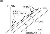
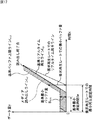
図形データ演算部13は、ステップS22において、メディア読み出しラインLrにおけるすべての読み出し開始点(Xi,Yi)を検出すると、ステップS23に進み、図8に示すように、すべての読み出し開始点について、その読み出し開始点(Xi,Yi)を通り、傾きが基準再生レートRpの直線L(i)を、リアルタイム再生ラインの候補として求め、ステップS24に進む。
【0108】
ここで、リアルタイム再生ラインの候補としての直線L(i)は、例えば、次式で表すことができる。
【0109】
y=Rpx+Yi−RpXi
【0110】
ステップS24では、図形データ演算部13は、ステップS23で求めたリアルタイム再生ラインの候補L(i)それぞれに対する再生遅延時間T(i)を求め、ステップS25に進む。
【0111】
ここで、再生遅延時間は、上述したように、リアルタイム再生ラインのx切片で表される。従って、リアルタイム再生ラインの候補L(i)に対する再生遅延時間T(i)は、例えば、次式により求めることができる。
【0112】
T(i)=−(Yi−RpXi)/Rp
【0113】
ステップS25では、図形データ演算部13は、ステップS24で求められた再生遅延時間T(i)を最大にするサフィックスiを求める。いま、再生遅延時間T(i)を最大にするサフィックスiをIと表すこととすると、ステップS25では、さらに、図形データ演算部13が、そのサフィックスIで特定される読み出し開始点(XI,YI)を律速点として求める。そして、図形データ演算部13は、サフィックスIで特定されるリアルタイム再生ラインの候補L(I):y=Rpx+YI−RpXIをリアルタイム再生ラインとして求め、リアルタイム再生ライン算出処理を終了する。
【0114】
以上のリアルタイム再生ライン算出処理によれば、時刻が0からT(I)までは、式y=0で、時刻がT(I)以降は、式y=Rpx+YI−RpXIで、それぞれ表されるリアルタイム再生ラインLpが求められるとともに、最小再生遅延時間Twが、T(I)として求められる。ここで、時間T(I)に代えて、最小再生遅延時間Twを用いると、リアルタイム再生ラインLpは、時刻が0からTwまでは、式y=0で、時刻がTw以降は、式y=Rpx+YI−RpXIで、それぞれ表される。
【0115】
なお、再生遅延時間T(i)を最大にするサフィックスiが複数存在する場合には、そのうちのいずれのサフィックスiを、再生遅延時間T(i)を最大にするサフィックスIとして用いてもかまわない。
【0116】
次に、光ディスク31からのAVデータの読み出しが、メディア読み出しラインLrを描いて行われる場合に、そのAVデータのリアルタイム再生を行うことができるかどうかを判定するには、リアルタイム再生ラインLpの他、バッファ上限ラインLupを導入する必要がある。
【0117】
そこで、図9は、バッファ上限ラインLupを示している。
【0118】
バッファ上限ラインLupは、バッファ19に記憶することができるデータのデータ量の上限値の総量の時間推移を表し、リアルタイム再生ラインLpを上方向に平行移動した折れ線となる。
【0119】
上述したように、メディア読み出しラインLrは、光ディスク31から読み出されてバッファ19にバッファリングされるAVデータのデータ量を表し、バッファ上限ラインLupは、バッファ19に記憶することができるデータのデータ量の上限値を表すから、バッファ上限ラインLupが、メディア読み出しラインLrを下回ることは、バッファ19にオーバーフローが発生することを意味する。従って、バッファ上限ラインLupが、メディア読み出しラインLrを下回ると、再生が途切れることとなるから、これを回避する必要がある。なお、あるバッファ上限ラインLupが、メディア読み出しラインLrを下回ることを回避する方法としては、ディスクドライブ2において回転待ち(トラックジャンプ)を行い、その間、AVデータの読み出しを行わないようにする方法がある。但し、この方法によって、バッファ上限ラインLupが、メディア読み出しラインLrを下回ることを回避した場合、その回避後のメディア読み出しラインLrが、右方向にシフトするように変化してしまうので、メディア読み出しラインLrを求め直す必要がある。
【0120】
バッファ上限ラインLupとリアルタイム再生ラインLpとの差(バッファ上限ラインLupとリアルタイム再生ラインLpとの間のy軸方向(垂直方向)の距離)は、バッファ19に必要とされるバッファサイズを表す。従って、バッファ19に必要とされるバッファサイズを小さくするには、バッファ上限ラインLupは、なるべく下方向に位置するのが望ましい。
【0121】
以上から、AVデータのリアルタイムでの再生を保証しながら、バッファ19に必要とされるバッファサイズを最小とするには、バッファ上限ラインLupを、図9に示すように、メディア読み出しラインLrに対して、上から1以上の点において接するように配置する必要がある。
【0122】
なお、バッファ上限ラインLupが、メディア読み出しラインLrに対して、上から1以上の点において接している場合のバッファ19のバッファサイズ(バッファ上限ラインLupとリアルタイム再生ラインLpとの間の垂直方向の距離)が、リアルタイム再生に必要とされる最小限のバッファ19のバッファである最小バッファ量Bminである。
【0123】
この最小バッファ量Bminは、ディスクドライブ2において回転待ちを行うようにすることによって、小さくすることが可能である。但し、回転待ちは、メディア読み出しラインLr上の、律速点よりも右側の点の位置でなければ行うことができない。
【0124】
ここで、バッファ上限ラインLupが、メディア読み出しラインLrに対して上から接する1以上の点を、以下、適宜、最小バッファ点という。
【0125】
図1の図形データ演算部13は、図2のステップS2において、メディア読み出しラインLrを近似するライン近似図形を求めるにあたって、リアルタイム再生ラインLpの他、バッファ上限ラインLupを用いる。
【0126】
そこで、図10のフローチャートを参照して、バッファ上限ラインLupを求めるバッファ上限ライン算出処理について説明する。
【0127】
バッファ上限ライン算出処理では、まず最初に、ステップS31において、図形データ演算部13は、メディア読み出しラインLrについて、シークが開始する点であるシーク開始点を検出し、ステップS32に進む。ステップS32では、図形データ演算部13は、メディア読み出しラインLrの、時間経過方向に向かって最初のシーク開始点におけるAVデータの読み出しデータ量Dを検出し、ステップS33に進む。
【0128】
ステップS33では、図形データ演算部13は、リアルタイム再生ラインLpを、ステップS32で検出したデータ量Dだけ上方向(y軸方向)に移動し、その移動後のリアルタイム再生ラインLpを、バッファ上限ラインLupの候補(候補ライン)とする。
【0129】
ここで、上述のように、リアルタイム再生ラインLpを移動したものが、バッファ上限ラインLupの候補とされるため、バッファ上限ライン算出処理は、図7のリアルタイム再生ライン算出処理において、リアルタイム再生ラインLpが求められた後に行う必要がある。
【0130】
なお、図7のリアルタイム再生ライン算出処理において、上述したように、時刻が0からT(I)までは、式y=0で、時刻がT(I)以降は、式y=Rpx+YI−RpXIで、それぞれ表されるリアルタイム再生ラインLpが求められた場合、ステップS33で求められるバッファ上限ラインLupの候補である候補ラインは、時刻が0からT(I)までは、式y=Dで、時刻がT(I)以降は、式y=Rpx+YI−RpXI+Dで、それぞれ表される。
【0131】
図形データ演算部13は、ステップS33において、バッファ上限ラインLupの候補である候補ラインを求めると、ステップS34に進み、ステップS31で検出したメディア読み出しラインLr上の2番目以降のシーク開始点の中で、候補ラインよりも上方向に位置するものがあるかどうかを判定する。
【0132】
ステップS34において、メディア読み出しラインLr上の2番目以降のシーク開始点の中で、候補ラインよりも上方向に位置するものがないと判定された場合、即ち、図11に示すように、メディア読み出しラインLr上の2番目以降のシーク開始点すべてが、候補ラインよりも下方向に位置するか、または候補ラインに接している場合(候補ラインが、メディア読み出しラインLrを下回らない場合)、ステップS35に進み、図形データ演算部13は、候補ラインを、バッファ上限ラインLupとして求め、バッファ上限ライン算出処理を終了する。
【0133】
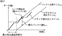
また、ステップS34において、メディア読み出しラインLr上の2番目以降のシーク開始点の中で、候補ラインよりも上方向に位置するものがあると判定された場合、即ち、メディア読み出しラインLr上の2番目以降の任意のシーク開始点の座標を(X,Y)として、式Y>RpX+YI−RpXI+Dを満たすシーク開始点(X,Y)が存在する場合、ステップS36に進み、図形データ演算部13は、候補ラインよりも上方向に位置するシーク開始点それぞれを通る、傾きが、基準再生レートRpの直線を求める。さらに、ステップS36では、図形演算部13は、候補ラインよりも上方向に位置するシーク開始点それぞれを通る、傾きが、基準再生レートRpの直線の中から、y切片が最大のものを、バッファ上限ラインLupを構成する直線として検出し、ステップS37に進む。
【0134】
ステップS37では、図形演算部13は、図12に示すように、バッファ上限ラインLupを構成する直線について、その直線が、シーク開始点と接する点を、最小バッファ点として、その最小バッファ点とリアルタイム再生ラインLpとの垂直方向の距離を、最小バッファ量Bminとして求める。さらに、ステップS37では、図形演算部13は、時刻が0から最小再生遅延時間Twまでは、式y=Bminで、時刻が最小再生遅延時間Tw以降は、y切片最大直線で、それぞれ表される折れ線を、バッファ上限ラインLupとして求め、バッファ上限ライン算出処理を終了する。
【0135】
以上のバッファ上限ライン算出処理によれば、バッファ上限ラインLupとともに、最小バッファ量Bminが求められる。
【0136】
次に、光ディスク31に、ビデオデータだけや、オーディオデータだけの、単一のAVデータだけのファイルが記録されており、そのAVデータ、即ち、ビデオデータまたはオーディオデータだけを再生する場合には、上述の方法を、そのまま用いて、リアルタイム再生ラインLpおよび最小再生遅延時間Tw、並びにバッファ上限ラインLupおよび最小バッファ量Bminを求めれば良いが、例えば、光ディスク31に別々のファイルとして記録されているビデオデータとオーディオデータを、全体としては、1つファイルのAVデータとして再生する場合には、以下のように、リアルタイム再生ラインLpおよび最小再生遅延時間Tw、並びにバッファ上限ラインLupおよび最小バッファ量Bminを求める必要がある。
【0137】
即ち、光ディスク31において、ビデオデータとオーディオデータ等の複数のデータが、別々のファイルとして記録されていても、再生するときには、1つのAVデータのファイルとみなせるように、ビデオデータとオーディオデータのファイルのリストを、VFL(Virtual File List)ファイルと呼ばれるファイルに記述しておき、そのVFLファイルにしたがい、例えば、ビデオデータとそれに付随するオーディオデータを同時に再生する方法がある。
【0138】
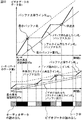
この場合、ビデオデータとオーディオデータを、光ディスク31から並列に読み出す必要がある。そこで、まず、上述したようにして、ビデオデータとオーディオデータについて、図13に示すように、メディア読み出しラインVLrとALrをそれぞれ求め、さらに、リアルタイム再生ラインVLpとALpをそれぞれ求める。なお、ビデオデータとオーディオデータを、光ディスク31から並列に読み出すといっても、実際には、図13に示すように、ビデオデータとオーディオデータは、例えば、再生順に、必要に応じてシークを行いながら、時分割で、光ディスク31から読み出される。
【0139】
ビデオデータとオーディオデータについて、リアルタイム再生ラインVLpとALpをそれぞれ求めた後、ビデオデータのリアルタイム再生ラインVLpから得られる最小再生遅延時間VTwと、オーディオデータのリアルタイム再生ラインALpから得られる最小再生遅延時間ATwとが異なる場合は、ビデオデータのリアルタイム再生ラインVLpと、オーディオデータのリアルタイム再生ラインALpのうちの、最小再生遅延時間が小さい方を、大きい方に一致させるように、右方向にずらす。一般には、ビデオデータの最小再生遅延時間VTwの方が、オーディオデータの最小再生遅延時間ATwよりも大となるので、オーディオデータの最小再生遅延時間ATwが、ビデオデータの最小再生遅延時間VTwに一致するように、オーディオデータのリアルタイム再生ラインALpが、右方向にずらされ、これにより、リアルタイム再生ラインALp’とされる。
【0140】
そして、以上のようにして得られたビデオデータのリアルタイム再生ラインVLpを用いて、図9乃至図12で説明したように、ビデオデータのバッファ上限ラインVLupを求めるとともに、オーディオデータのリアルタイム再生ラインALp’を用いて、やはり、図9乃至図12で説明したように、オーディオデータのバッファ上限ラインALupを求める。
【0141】
なお、ここでは、光ディスク31から読み出されたビデオデータとオーディオデータそれぞれを記憶するバッファ19として、独立のバッファを採用することを前提としている。但し、光ディスク31から読み出されたビデオデータとオーディオデータそれぞれを記憶するバッファ19としては、共通のバッファを採用することも可能であり、この場合、ビデオデータとオーディオデータの最小バッファ量は、独立のバッファを採用する場合に比較して小さくなるケースが存在する。
【0142】
また、多くのエクステントから構成されるファイルについては、基準再生レートでの最小バッファ量Bminと最小再生遅延時間Twの算出には、時間を要する場合があるので、基準再生レートでの最小バッファ量Bminと最小再生遅延時間Twは、光ディスク31にファイルを作成したときに求めておき、リアルタイム再生可否判定を行うときに、即座に参照することができるようにしておくようにすることができる。なお、ファイルの作成時求めた基準再生レートでの最小バッファ量Bminと最小再生遅延時間Twは、例えば、そのファイルのエントリ(file entry)や、そのファイルの各種の属性が記述される拡張属性ファイルが存在する場合には、その拡張属性ファイル中に記述しておくことが可能である。
【0143】
ところで、上述の場合においては、リアルタイム再生ラインLpの傾きである基準再生レートRpを、1倍速再生を行うときの再生レートとして、最小バッファ量Bminと最小再生遅延時間Twを求めるようにしたことから、ユーザが入力部12を操作することにより入力する要求再生レートが、1倍速再生に対応する再生レート、即ち、基準再生レートRpに一致していれば、基準再生レートRpについて求められた最小バッファ量Bminと最小再生遅延時間Twを、許容バッファ量と許容再生遅延時間とそれぞれ比較することにより、リアルタイム再生可否判定を、容易に行うことができる。即ち、最小バッファ量Bminが許容バッファ量以下であり、最小再生遅延時間Twも許容再生遅延時間以下であれば、要求再生レートである1倍速再生に対応する再生レートでのリアルタイム再生を行うことができ、最小バッファ量Bminが許容バッファ量より大であるか、または最小再生遅延時間Twが許容再生遅延時間より大であれば、要求再生レートである1倍速再生に対応する再生レートでのリアルタイム再生は行うことができない。
【0144】
一方、要求再生レートが、基準再生レートRpに一致していない場合、その要求再生レートを傾きとして有するリアルタイム再生ラインLpとバッファ上限ラインLupを求め、さらに、その要求再生レートについて、最小バッファ量Bminと最小再生遅延時間Twを求めて、許容バッファ量と許容再生遅延時間とそれぞれ比較しなければ、要求再生レートでのリアルタイム再生が可能であるかどうかのリアルタイム再生可否判定を行うことができず、面倒である。さらに、要求再生レートを傾きとして有するリアルタイム再生ラインLpとバッファ上限ラインLupを求めるには、メディア読み出しラインLrが必要であり、従って、要求再生レートが変更されるたびに、メディア読み出しラインLrが必要となる。このため、メディア読み出しラインLrも、要求再生レートが変更されるたびに求め直すか、あるいは、記憶しておかなければならず、やはり、面倒である。
【0145】
そこで、図1のディスク装置では、要求再生レートでのリアルタイム再生が可能であるかどうかのリアルタイム再生可否判定を、以下のようにして、容易に行うことができるようになっている。
【0146】
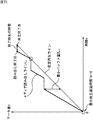
即ち、メディア読み出しラインLrは、図14に示すように、基準再生レートRpについて、最小再生遅延時間Twを与えるリアルタイム再生ラインLpと、最小バッファ量Bminを与えるバッファ上限ラインLupに挟まれる範囲に含まれる。そこで、いま、そのリアルタイム再生ラインLpおよびバッファ上限ラインLup、さらには、y軸、光ディスク31からのAVデータの読み出しが終了する読み出し終了点(メディア読み出しラインLr上の最後の点(時間的に最も後の点))を通るx軸に平行な直線で囲まれる領域の外形(図14において影を付してある部分)を、その形状から、ホッケースティック形と呼ぶこととすると、このホッケースティック形は、メディア読み出しラインLrを近似する図形であるということができる。
【0147】
ホッケースティック形は、例えば、基準再生レートRp、その基準再生レートRpでの最小再生遅延時間Twと最小バッファ量Bmin、読み出し終了点によって特定することができる。そこで、図1の図形データ演算部13は、例えば、これらの基準再生レートRp、最小再生遅延時間Tw、最小バッファ量Bmin、読み出し終了点を、メディア読み出しラインLrを近似するライン近似図形としてのホッケースティック形を特定する図形データとして求め、図形データ記憶部14に記憶させる。なお、読み出し終了点は、光ディスク31からのAVデータの読み出しが終了する読み出し終了時刻Tendと、それまでに光ディスク31から読み出されたAVデータのデータ量(の総量)を、それぞれx座標とy座標とするが、図形データとしては、読み出し終了点のx座標とy座標の両方は、必ずしも必要ではなく、いずれか一方だけであっても良い。また、ホッケースティック形を特定する図形データは、上述したものに限定されるものではない。
【0148】
図1のリアルタイム再生可否判定部15は、以上のようなホッケースティック形のライン近似図形に基づき、要求再生レートでのデータのリアルタイム再生に必要とされる最小バッファ量(要求再生レートでの最小バッファ量)と、最小再生遅延時間(要求再生レートでの最小再生遅延時間)とを、次にようにして算出する。
【0149】
即ち、要求再生レートでのリアルタイム再生を保証するには、その要求再生レートでのリアルタイム再生ラインが、メディア読み出しラインLrを上回ることがあってはならない。
【0150】
一方、基準再生レートについて求められたホッケースティック形のライン近似図形は、メディア読み出しラインLrを含むから、要求再生レートでのリアルタイム再生ラインが、基準再生レートについて求められたホッケースティック形のライン近似図形よりも下の位置か、または接する位置に存在すれば、要求再生レートでのリアルタイム再生ラインが、メディア読み出しラインLrを上回ることはない。
【0151】
従って、要求再生レートでのリアルタイム再生を保証するには、要求再生レートでのリアルタイム再生ラインが、図15に示すように、基準再生レートについて求められたホッケースティック形のライン近似図形よりも下の位置か、または接する位置(以下、適宜、ライン図形以下の位置という)に描画されなければならない。
【0152】
このような要求再生レートでのリアルタイム再生ラインは、例えば、ライン図形以下の位置に存在し、ライン図形の1点以上と接する直線であって、要求再生レートを傾きとする直線(以下、適宜、再生要求直線という)を算出し、その再生要求直線のx切片を算出することによって求めることができる。即ち、この場合、要求再生レートでのリアルタイム再生ラインは、図15に示すように、時刻0からx切片までが式y=0の直線で表され、時刻がx切片以降が再生要求直線で表される折れ線となる。
【0153】
さらに、この場合、図15に示すように、要求再生レートでのリアルタイム再生ライン(再生要求直線)のx切片は、再生要求レートでの最小再生遅延時間を近似する値となり、要求再生レートでのリアルタイム再生ラインから、ホッケースティック形のライン近似図形を構成するバッファ上限ラインLupまでの垂直方向の距離の最大値は、再生要求レートでの最小バッファ量を近似する値となる。
【0154】
このようにして、再生要求レートでの最小再生遅延時間(の近似値)と最小バッファ量(の近似値)を求め、許容バッファ量と許容再生遅延時間とそれぞれ比較することにより、再生要求レートでのリアルタイム再生可否判定を、容易に行うことができる。
【0155】
なお、図15の実施の形態では、要求再生レートが、基準再生レートRpの2倍になっている。
【0156】
ここで、以下、適宜、基準再生レートRpでのリアルタイム再生ラインLp、バッファ上限ラインLup、最小再生遅延時間Tw、最小バッファ量Bminを、それぞれ基準リアルタイム再生ラインLp、基準バッファ上限ラインLup、基準最小再生遅延時間Tw、基準最小バッファ量Bminという。
【0157】
以上のように、基準再生レートRp、基準最小再生遅延時間Tw、基準最小バッファ量Bmin、読み出し終了点が、図形データとして、図形データ記憶部14に記憶されていれば、その図形データによって特定されるホッケースティック形に基づき、要求再生レートでの最小再生遅延時間と最小バッファ量を求め、再生要求レートでのリアルタイム再生が可能であるかどうかのリアルタイム再生可否判定を行うことができる。
【0158】
なお、要求再生レートでのリアルタイム再生を保証するには、要求再生レートでのリアルタイム再生ラインが、メディア読み出しラインLrを上回ってはならない他、メディア読み出しラインLrが、要求再生レートでのバッファ上限ラインを上回ってはならない。但し、メディア読み出しラインLrが、要求再生レートでのバッファ上限ラインを上回るケース、即ち、バッファ19がオーバーフローするケースは、上述したように、ディスクドライブ2において回転待ちを行うことにより回避することができる。
【0159】
ところで、上述の場合には、ホッケースティック形を求めるときに、基準再生レートとして、1倍速再生に対応する再生レートを用いることとしたが、ホッケースティック形が分かれば、要求再生レートでの最小再生遅延時間と最小バッファ量を求めることができるから、基準再生レートとしては、1倍速再生に対応する再生レートを、必ずしも用いる必要はない。むしろ、基準再生レートとして、1倍速再生に対応する再生レートを用いることによって、メディア読み出しラインLrをそれほど精度良く近似しないホッケースティック形が得られることがある。
【0160】
即ち、メディア読み出しラインLrが、例えば、図16に示すように、光ディスク31からのAVデータの読み出し開始後まもなく、長時間のシークが行われ、その後、シークが行われずに、AVデータの読み出しが連続して行われるようなケースを表す場合には、基準再生レートとして、1倍速再生に対応する再生レートを用いると、メディア読み出しラインLrを近似するライン近似図形として、幅が広いホッケースティック形が得られることがある。
【0161】
この場合、基準再生レートよりも大きい要求再生レートでのリアルタイム再生ライン(再生要求直線)は、図16に示すように、x切片が大きなものとなる。要求再生レートでのリアルタイム再生ラインのx切片は、再生要求レートでの最小再生遅延時間を表すから、この場合、再生要求レートでの最小再生遅延時間(の近似値)としては、本来必要とされる最小再生遅延時間の真の値よりも非常に大きな値が得られることになる。さらに、要求再生レートでのリアルタイム再生ラインのx切片が大になると、そのリアルタイム再生ラインと、ホッケースティック形のライン近似図形を構成する基準バッファ上限ラインLupとの垂直方向の距離で表される再生要求レートでの最小バッファ量(の近似値)も大になり、本来必要とされる最小バッファ量の真の値よりも非常に大きな値が得られることになる。
【0162】
一方、その再生レートでの再生が可能であるかどうか、あるいは、その再生レートで再生が行われ得るかどうか等にかかわらず、ある仮想的な再生レートを想定することによって、メディア読み出しラインLrを、より精度良く近似するライン近似図形としてのホッケースティック形を得ることができる。
【0163】
そこで、いま、メディア読み出しラインLrを、より精度良く近似するライン近似図形を得ることができる仮想的な再生レートを、仮想再生レートというものとすると、基準再生レートとしては、この仮想再生レートを採用することができる。
【0164】
仮想再生レートを用いて求められるライン近似図形によれば、図17に示すように、メディア読み出しラインLrを、より精度良く近似することができる。そして、そのようなライン近似図形を用いて、要求再生レートでのリアルタイム再生ラインを求め、さらに、再生要求レートでの最小再生遅延時間と最小バッファ量を求めることにより、それぞれの値として、本来必要とされる最小再生遅延時間と最小バッファ量の真の値に近い値が得られることになる。
【0165】
図16と図17は、同一のメディア読み出しラインLrについて、基準再生レートとして、1倍速再生に対応する再生レートと、仮想再生レートをそれぞれ用いて、ライン近似図形としてのホッケースティック形を求め、さらに、再生要求レートでの最小再生遅延時間および最小バッファ量を求めた場合をそれぞれ示しているが、図16と図17の比較して明らかなように、仮想再生レートを用いてホッケースティック形を求めた場合(図17)の方が、1倍速再生に対応する再生レートを用いてホッケースティック形を求めた場合(図16)よりも、再生要求レートでの最小再生遅延時間および最小バッファ量として、小さな値が得られている。
【0166】
次に、仮想再生レートを基準再生レートとしてホッケースティック形を求める場合、その仮想再生レートを、どのような再生レートとするかが問題となる。
【0167】
そこで、仮想再生レートは、例えば、図18に示すように、最小バッファ量Bminがより小さくなるように、リアルタイム再生ラインを描くことができる値とすることができる。
【0168】
即ち、仮想再生レートでのリアルタイム再生ラインを、仮想再生ラインというものとすると、仮想再生ラインは、メディア読み出しラインLrの1点以上において、下から接するように描けば良いから、仮想再生ラインの候補となる直線は、無数に存在する。そこで、仮想再生ラインとしては、そのような無数の候補の中の最小バッファ量を最小にするものを採用することができる。
【0169】
具体的には、例えば、図18に示すように、x切片と傾きが小の仮想再生ラインの候補Lp#1と、x切片と傾きが大の仮想再生ラインの候補Lp#2とについて考えた場合、x切片が小の仮想再生ラインの候補Lp#1の最小再生遅延時間Tw#1は、x切片が大の仮想再生ラインの候補Lp#2の最小再生遅延時間Tw#2よりも小になる。
【0170】
一方、仮想再生ラインと、メディア読み出しラインLrとの垂直方向の距離の最大値で表される最小バッファ量Bminについては、x切片と傾きが小の仮想再生ラインの候補Lp#1の最小バッファ量Bmin#1より、x切片と傾きが大の仮想再生ラインの候補Lp#2の最小バッファ量Bmin#2の方が小さくなる。
【0171】
従って、最小バッファ量Bminがより小さい、という基準で、仮想再生ラインを求める場合には、仮想再生ラインの候補Lp#2が、仮想再生ラインとして決定され、その傾きが仮想再生レートとして求められる。なお、最小再生遅延時間Twが短い、という基準で、仮想再生ラインを求める場合には、仮想再生ラインの候補Lp#1が、仮想再生ラインとして決定される。
【0172】
上述のように、仮想再生レートを基準再生レートとして用いてホッケースティック形を求める場合には、図1の図形データ演算部13は、そのホッケースティック形を特定する図形データを求めるために、図2のステップS2において仮想再生ラインを決定する。
【0173】
そこで、図19のフローチャートを参照して、仮想再生ラインを決定する仮想再生ライン決定処理について説明する。
【0174】
いま、メディア読み出しラインLr上の、i番目の読み出し開始点の座標を、(Xi,Yi)と表すこととすると、図形データ演算部13は、ステップS41において、メディア読み出しラインLr上の隣接する2つの読み出し開始点(Xi-1,Yi-1)および(Xi,Yi)のセットすべてについて、図20Aに示すように、その2つの読み出し開始点(Xi-1,Yi-1)および(Xi,Yi)を通る直線L(i)を求め、ステップS42に進む。
【0175】
ステップS42では、図形データ演算部13は、ステップS41で求めた直線L(i)の中から、メディア読み出しラインLrと交わっていないもののみを選択する。即ち、2つの読み出し開始点(Xi-1,Yi-1)および(Xi,Yi)を通る直線L(i)は、式y=(Yi−Yi-1)/(Xi−Xi-1)×x+(Yi-1Xi−YiXi-1)/(Xi−Xi-1)で表される。そして、メディア読み出しラインLr上の読み出し開始点(Xi-1,Yi-1)および(Xi,Yi)以外の任意の読み出し開始点の座標を、(X,Y)と表すこととすると、式Y≧(Yi−Yi-1)/(Xi−Xi-1)×X+(Yi-1Xi−YiXi-1)/(Xi−Xi-1)が満たされる場合、直線L(i)は、メディア読み出しラインLrと交わっていないこととなる。ステップS42では、このようにメディア読み出しラインLrと交わっていない直線L(i)だけが選択される。
【0176】
その後、ステップS43に進み、図形データ演算部13は、ステップS42で選択された直線を、仮想再生ラインの候補とし、その仮想再生ラインの候補それぞれについて、最小バッファ量を求める。即ち、図形データ演算部13は、図20Bに示すように、式y=(Yi−Yi-1)/(Xi−Xi-1)×x+(Yi-1Xi−YiXi-1)/(Xi−Xi-1)で表される仮想再生ラインの候補L(i)について、メディア読み出しラインLr上の読み出し開始点(Xi-1,Yi-1)および(Xi,Yi)以外のすべての読み出し開始点との垂直方向の距離(読み出し開始点における仮想再生ラインの候補L(i)とメディア読み出しラインLrとの差)を、最小バッファ量の候補として求める。そして、図形データ演算部13は、仮想再生ラインの候補L(i)について求められた最小バッファ量の候補のうち、値が最も大きいものを、その仮想再生ラインの候補L(i)の最小バッファ量として求める。
【0177】
以上のようにして、ステップS43において、ステップS42で選択された直線である仮想再生ラインの候補すべてについて、それぞれの最小バッファ量が求められた後は、ステップS44に進み、図形データ演算部13は、ステップS43において仮想再生ラインの候補それぞれについて求められた最小バッファ量の中から、値が最も小さいものを選択する。さらに、図形データ演算部13は、値が最も小さい最小バッファ量を与える仮想再生ラインの候補を、仮想再生ラインとして決定し、仮想再生ライン決定処理を終了する。
【0178】
なお、仮想再生ライン決定処理においては、最小バッファ量が最も小さい仮想再生ラインの候補が複数存在するケースがあり得るが、この場合には、いずれの候補を、仮想再生ラインとして決定してもかまわない。但し、最小バッファ量が最も小さい仮想再生ラインの候補が複数存在する場合において、その複数の仮想再生ラインの候補の傾きが異なるときには、例えば、傾きが、要求再生レートとしてユーザに要求されやすい再生レートに近い方を、仮想再生ラインとして決定することができる。また、複数の仮想再生ラインの候補の傾きが大きく異なるときには、例えば、その複数の仮想再生ラインの候補すべてを、仮想再生ラインとして決定することが可能である。この場合、仮想再生ラインが複数存在するので、ホッケースティック形も、その複数の仮想再生ラインと同様に複数得られることになる。そして、この場合、その複数のホッケースティック形のうちのいずれかから得られる最小バッファ量と最小再生遅延時間が、それぞれ許容バッファ量と許容再生遅延時間以下であれば、リアルタイム再生が可能であるということになる。
【0179】
次に、上述の場合には、最小バッファ量Bminがより小さくなるように、リアルタイム再生ライン(仮想再生ライン)を描くことができる再生レートを仮想再生レートとするようにしたが、その他、例えば、バッファ19に最大のデータ量のAVデータが記憶されるケースが、AVデータのリアルタイム再生中に均等に出現する場合の再生レートを、仮想再生レートとして求めるようにすることが可能である。
【0180】
即ち、いま、リアルタイム再生中にバッファ19に記憶されるAVデータのデータ量を、バッファ量というものとすると、ある時刻のバッファ量は、その時刻におけるメディア読み出しラインLrとリアルタイム再生ラインとの垂直方向の距離で表される。そして、バッファ量の最大値を、バッファ最大量というものとすると、例えば、図21に示すように、メディア読み出しラインLrの1つの点において下から接する直線を、仮想再生ライン(リアルタイム再生ライン)の候補とし、その仮想再生ラインの候補がメディア読み出しラインLrと接する点の左右それぞれにおいて、バッファ最大量が出現する仮想再生ラインの候補を、仮想再生ラインとして決定することができる。
【0181】
そこで、図22のフローチャートを参照して、上述のようにして仮想再生ラインを決定する仮想再生ライン決定処理について説明する。
【0182】
まず最初に、ステップS51において、図形データ演算部13は、メディア読み出しラインLr上のすべての読み出し開始点について、その読み出し開始点を通り、かつその読み出し開始点の右側と左側それぞれにバッファ最大量が出現する傾きを有する直線を、仮想再生ラインの候補として求める。即ち、ある読み出し開始点の座標を、(Xi,Yi)とすると、その読み出し開始点(Xi,Yi)を通る傾きがAの直線L(i)は、式y=Ax+Yi+AXiで表すことができる。図形データ演算部13は、直線L(i)の傾きAを少しずつ変化させ、その直線L(i)について、読み出し開始点(Xi,Yi)の右側と左側それぞれにバッファ最大量が出現する傾きAを求め、その傾きAを有し、読み出し開始点(Xi,Yi)を通る直線L(i)を、仮想再生ラインの候補として求める。
【0183】
なお、直線L(i)について、読み出し開始点(Xi,Yi)の右側と左側それぞれにバッファ最大量が出現しているかどうかは、例えば、次のようにして判定することができる。即ち、読み出し開始点(Xi,Yi)の右側と左側それぞれに存在する読み出し開始点におけるバッファ量(読み出し開始点と直線L(i)との垂直方向の距離)を求め、読み出し開始点(Xi,Yi)の右側と左側それぞれについて、最大のバッファ量を求める。この読み出し開始点(Xi,Yi)の右側と左側それぞれの最大のバッファ量が等しい場合には、読み出し開始点(Xi,Yi)の右側と左側それぞれにバッファ最大量が出現していることとなる。
【0184】
その後、ステップS52に進み、図形データ演算部42は、ステップS51で求めた仮想再生ラインの候補の中から、メディア読み出しラインLrを交わっていないものを選択する。即ち、ステップS52では、図形データ演算部42は、図23に示すように、ステップS51で求めた仮想再生ラインの候補のうち、メディア読み出しラインLrと交わっているものを、仮想再生ラインの候補から除外し、これにより、図24に示すように、メディア読み出しラインLrを交わっていないものだけを、仮想再生ラインの候補として残す。
【0185】
そして、ステップS53に進み、図形データ演算部42は、ステップS52で選択された仮想再生ラインの候補の中から、例えば、バッファ最大量が最小のものを選択し、その仮想再生ラインの候補を、仮想再生ラインに決定して、仮想再生ライン決定処理を終了する。
【0186】
図19の仮想再生ライン決定処理では、仮想再生ラインの候補の中から、単に、最小バッファ量Bminが小さいものを、仮想再生ラインとして決定するようにしたが、図22の仮想再生ライン決定処理では、読み出し開始点(Xi,Yi)の右側と左側それぞれにバッファ最大量が出現する仮想再生ラインの候補の中から、最小バッファ量Bminとなるバッファ最大量が最小のものを、仮想再生ラインとして決定するようにしたので、最小バッファ量Bminと最小再生遅延時間Twの両方を、ある程度小さくすることができる。
【0187】
即ち、仮想再生ラインの候補の中から、単に、最小バッファ量Bminが小さいものを、仮想再生ラインとして決定する場合、最小バッファ量Bminは小さくなるが、最小再生遅延時間Twは、一般に大きくなる。一方、読み出し開始点(Xi,Yi)の右側と左側それぞれにバッファ最大量が出現する仮想再生ラインの候補の中から、最小バッファ量Bminとなるバッファ最大量が小さいものを、仮想再生ラインとして決定する場合には、最小バッファ量Bminと最小再生遅延時間Twの両方を、ある程度小さくすることができる。
【0188】
なお、その他、例えば、図25に示すように、メディア読み出しラインLr上の最初の読み出し開始点と、最後の読み出し開始点を結んだ直線が、メディア読み出しラインLrと交わらない(交差しない)場合には、その直線を、仮想再生ラインとすることが可能である。この場合、最小再生遅延時間Twを0とすることができる。
【0189】
また、メディア読み出しラインLr上の最後の点である読み出し終了点と、その読み出し終了点におけるデータ量(y座標)に一致するデータ量となる仮想再生ライン上の点(以下、適宜、再生終了点という)との時間間隔(水平方向の距離)を、終了時先行時間というものとすると、この終了時先行時間が0となるリアルタイム再生ラインを、仮想再生ラインとすることが可能である。この場合、仮想再生ラインは、図26に示すように、メディア読み出しラインLr上の最後の読み出し開始点と読み出し終了点とを結んだ直線となり、仮想再生レートは、読み出しレートRrに等しくなる。終了時先行時間が0となるリアルタイム再生ラインを、仮想再生ラインとする場合、最小バッファ量Bminは、比較的大きな値になり得るが、最小再生遅延時間Twは、例えば、読み出しレートRrに近い再生レートでの再生が行われる場合に必要とされる最小再生遅延時間の真の値を、比較的精度良く近似する。ここで、終了先行時間は、AVデータの読み出しが終了してから、そのAVデータの再生が終了するまでの時間を表す。
【0190】
なお、一連のAVデータが、光ディスク32に連続して記録されており、その読み出し時にシークが発生しない場合、メディア読み出しラインLrは原点を通る直線となり、さらに、この場合、仮想再生ラインは、上述したいずれの方法で決定しても、メディア読み出しラインLrに一致する。
【0191】
次に、以上の場合においては、メディア読み出しラインLrそのものを、ホッケースティック形で、いわば直接的に近似することとしたが、メディア読み出しラインLrは、幾つかの成分に分け、その成分を近似する図形によって、いわば間接的に近似することが可能である。
【0192】
即ち、メディア読み出しラインLrは、メディアアクセス情報、読み出しレートRr、シーク時間(シーク時間関数)から求めることができる。従って、例えば、将来的に、高速な読み出しレートを有するディスクドライブが出現した場合や、ディスクドライブ2として、複数のピックアップを有し、実質的に高速な読み出しレートで、光ディスク31からAVデータを読み出すものを採用した場合などを考慮すると、メディア読み出しラインLrを構成するメディアアクセス情報に関する成分、読み出しレートに関する成分、シーク時間に関する成分は、それぞれ独立に扱うのが望ましい。
【0193】
そこで、メディア読み出しラインLrを、メディアアクセス情報に関する成分、読み出しレートに関する成分、シーク時間に関する成分に分けることを考える。
【0194】
メディア読み出しラインLrの成分のうち、読み出しレートに関する成分は、読み出しレートRrを傾きとして有し、原点を通る直線であるから、メディア読み出しラインLrから、容易に分離することができる。
【0195】
一方、メディア読み出しラインLrから、メディアアクセス情報に関する成分と、シーク時間に関する成分とを、それぞれ独立に分離しようとすると、その情報量が多くなる。そこで、メディア読み出しラインLrから、読み出しレートに関する成分を分離した残り、即ち、メディアアクセス情報に関する成分とシーク時間に関する成分との合成成分を考えると、その合成成分は、ディスクドライブ2において光ディスク31からデータを読み出すときに生じるシークの時間推移と、光ディスク31からデータの読み出しを無限大の読み出しレートで行うときの読み出しデータ量の総量の時間推移とを表すラインとなる。
【0196】
そこで、図27に示すように、メディア読み出しラインLrを、読み出しレートに関する成分を表すラインと、メディアアクセス情報に関する成分およびシーク時間に関する成分の合成成分を表すラインとに分離して取り扱うこととする。
【0197】
ここで、読み出しレートに関する成分を表すラインは、上述したように、読み出しレートRrを傾きとして有し、原点を通る直線であり、シークが発生しないと仮定した場合の、光ディスク31からのデータの読み出しデータ量の総量の時間推移を表す。そこで、以下、適宜、読み出しレートに関する成分を表すラインを、無シーク読み出しラインLnsという。また、メディアアクセス情報に関する成分およびシーク時間に関する成分の合成成分を表すラインを、以下、適宜、メディアシークラインLsという。
【0198】
メディア読み出しラインLrを、無シーク読み出しラインLnsとメディアシークラインLsに分離した場合、メディア読み出しラインLrは、無シーク読み出しラインLnsとメディアシークラインLsとを、いわば時間方向(x軸方向)に加算することで求めることができる。
【0199】
無シーク読み出しラインLnsは、光ディスク31を駆動するディスクドライブ2の読み出しレートRr(さらには、ディスクドライブ2が有するピックアップの数などのディスクドライブ2の仕様)にのみ依存する。従って、無シーク読み出しラインLnsは、再生対象のAVデータのファイルごとに用意する必要はない。また、無シーク読み出しラインLnsは、読み出しレートRrの傾きを有する、原点を通る直線であるから、読み出しレートRrが分かっていれば描画することができ、図形によって近似するまでもなく、読み出しレートRrだけで特定することができる。
【0200】
一方、メディアシークラインLsは、メディアアクセス情報に関する成分およびシーク時間に関する成分の合成成分を表すラインであるから、ディスクドライブ2の仕様の他、再生対象のAVデータの、光ディスク31上の配置位置などにも依存する。そして、メディアシークラインLsは、シークが行われているときには、傾きが0となり、光ディスク31からのデータの読み出しが行われているときには、傾きが無限大となるから、その特定には、例えば、シークの開始時刻、シークが行われている時間、光ディスク31からのデータの読み出しが行われている各時刻において光ディスク31から読み出されるデータ量といった多くの情報が必要となる。そこで、ここでは、メディア読み出しラインLrを図形によって近似した場合と同様に、メディアシークラインLsを図形によって近似し、その図形を、少ないデータで特定することを考える。
【0201】
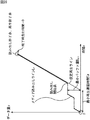
メディアシークラインLsを図形によって近似する場合、まず最初に、基準再生レートとなる仮想再生レートを決定する必要がある。ここでは、例えば、図28に示すように、メディアシークラインLsの始点と終点とを結んだ直線を、平均再生ラインというものとして、その平均再生ラインの傾きを、仮想再生レートとすることとする。この場合、仮想再生レートでのリアルタイム再生ラインである仮想再生ラインは、傾きが仮想再生レートで、メディアシークラインLsに対して下から接する直線となる。また、仮想再生レートでのバッファ上限ラインを、仮想バッファ上限ラインというものとすると、仮想バッファ上限ラインは、傾きが仮想再生レートで、メディアシークラインLsに対して上から接する直線となる。なお、仮想再生ラインと仮想バッファ上限ラインは、平均再生ラインを、右または左に、それぞれ平行移動した直線に一致する。
【0202】
そして、仮想再生ラインと仮想バッファ上限ライン、さらには、x軸、およびメディアシークラインLsの終点を通り、x軸に平行な直線で構成される平行四辺形を考えると、メディアシークラインLsは、この平行四辺形に含まれることとなる。この平行四辺形は、メディアシークラインLsを近似しており、以下、適宜、シークライン近似平行四辺形という。
【0203】
いま、シークライン近似平行四辺形の底辺の長さを、底辺時間といい、原点からシークライン近似平行四辺形の右下の頂点までの水平距離を、基準遅延時間ということとする。この場合、シークライン近似平行四辺形は、例えば、仮想再生レート、底辺時間、基準遅延時間、およびメディアシークラインLsの終点(のx座標またはy座標のうちの少なくとも一方)という少ないデータによって特定される。なお、シークライン近似平行四辺形を特定するデータは、上述のものに限定されるものではなく、その他、例えば、シークライン近似平行四辺形の4つの頂点の座標などを採用することが可能である。
【0204】
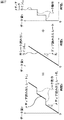
ところで、上述したように、メディア読み出しラインLrは、無シーク読み出しラインLnsとメディアシークラインLsとを、いわば時間方向に加算することで求めることができる。一方、シークライン近似平行四辺形は、メディアシークラインLsを含んでいる。従って、図29に示すように、無シーク読み出しラインLnsとシークライン近似平行四辺形とを、時間方向に加算した場合には、メディア読み出しラインLrを含み、そのメディアシークラインLsを近似する図形、即ち、ライン近似図形を得ることができる。
【0205】
ここで、無シーク読み出しラインLnsとシークライン近似平行四辺形とを、時間方向に加算して得られるライン近似図形は、底辺を、シークライン近似平行四辺形と同一とし、シークライン近似平行四辺形の上底(上辺)を実質読み出し時間だけ時間方向に移動した平行四辺形(図29において右側に示す影を付してある部分)となる。なお、実質読み出し時間とは、無シーク読み出しラインLnsの終点の時刻を意味し、例えば、再生対象のAVデータのファイルのデータ量を、読み出しレートRrで除算することにより求めることができる。
【0206】
この場合、ライン近似図形における基準遅延時間が、(基準)最小再生遅延時間Twとなり、その最小再生遅延時間Twにおけるライン近似図形の垂直方向の幅が(基準)最小バッファ量Bminとなる。
【0207】
なお、無シーク読み出しラインLnsとシークライン近似平行四辺形とを時間方向に加算して得られるライン近似図形としての平行四辺形においては、ライン近似図形をホッケースティック形とする場合と同様に、リアルタイム再生ライン、バッファ上限ライン、仮想再生レートを規定することができる。即ち、ライン近似図形としての平行四辺形においては、その左右の辺のうちの右側の辺が、リアルタイム再生ライン(仮想再生ライン)を表し、左側の辺が、バッファ上限ラインを表す。そして、リアルタイム再生ラインおよびバッファ上限ラインは、同一の傾きを有し、その傾きが、仮想再生レートを表す。図29では、ライン近似図形としての平行四辺形において規定されるリアルタイム再生ライン、バッファ上限ライン、仮想再生レートを、それぞれ、合成後仮想再生ライン、合成後バッファ上限ライン、合成後仮想再生レートとして示してある。
【0208】
また、上述の場合には、メディアシークラインLsを近似する図形として、平行四辺形を採用することとしたが、メディアシークラインLsを近似する図形としては、その他、例えば、上述したホッケースティック形などを採用することも可能である。但し、メディアシークラインLsを近似する図形として、平行四辺形を採用する場合には、メディア読み出しラインLrを近似するライン近似図形は、その平行四辺形を右方向に延ばしたような平行四辺形となるため、そのライン近似図形によって規定される最小バッファ量は、メディアシークラインLsを近似する平行四辺形によって規定される最小バッファ量より小さくなる。これに対して、メディアシークラインLsを近似する図形として、ホッケースティック形を採用する場合には、メディア読み出しラインLrを近似するライン近似図形によって規定される最小バッファ量は、メディアシークラインLsを近似するホッケースティック形によって規定される最小バッファ量と基本的に変わらない。
【0209】
次に、図30のフローチャートを参照して、上述のように、メディアシークラインLsを近似する平行四辺形と、無シーク読み出しラインLnsとから、メディア読み出しラインLrを近似するライン近似図形を特定する図形データを求める場合の、図2のステップS2の処理の詳細について説明する。
【0210】
図形データ演算部13は、まず最初に、ステップS61において、例えば、メディア読み出しラインLrから、メディアシークラインLsと無シーク読み出しラインLnsとを求める。ここで、メディアシークラインLsと無シーク読み出しラインLnsは、メディア読み出しラインLrから、例えば、図31に示すようにして求めることができる。
【0211】
即ち、まず、無シーク読み出しラインLnsは、読み出しレートRrを傾きとして有する、原点を通る直線として求めることができる。また、メディアシークラインLsは、光ディスク31からのデータの読み出しが無シーク読み出しラインLnsにしたがって行われるとした場合に、メディア読み出しラインLr上の各点におけるデータ量dだけのデータを読み出すのに要する時間d/Rrを求め、メディア読み出しラインLr上の各点を、時間d/Rrだけ左方向(時間的に遡る方向)にシフトすることによって求めることができる。
【0212】
図30に戻り、ステップS61において、メディアシークラインLsと無シーク読み出しラインLnsとを求めた後は、ステップS62に進み、図形データ演算部13は、メディアシークラインLsの始点と終点と結ぶ直線である平均再生ラインを求め、その平均再生ラインの傾きを、基準再生レートとなる仮想再生レートとして求める。
【0213】
そして、ステップS63に進み、図形データ演算部13は、メディアシークラインを囲む平行四辺形であって、平均再生ラインに平行な辺を有するものであるシークライン近似平行四辺形を求める。即ち、図形データ演算部13は、傾きが仮想再生レートで、メディアシークラインLsに対して下から接する直線となる仮想再生ラインを求めるとともに、傾きが仮想再生レートで、メディアシークラインLsに対して上から接する直線となるバッファ上限ラインを求める。そして、図形データ演算部13は、その仮想再生ラインと仮想バッファ上限ライン、さらには、x軸、およびメディアシークラインLsの終点を通り、x軸に平行な直線で構成される平行四辺形を、シークライン近似平行四辺形として求める。
【0214】
その後、ステップS64に進み、図形データ演算部13は、シークライン近似平行四辺形を特定するデータとして、例えば、仮想再生レート、底辺時間、基準遅延時間、およびメディアシークラインLsの終点(のx座標またはy座標のうちの少なくとも一方)を求め、そのデータと、無シーク読み出しラインLnsの傾き、即ち、読み出しレートRrを、メディア読み出しラインLrを近似するライン近似図形を特定する図形データとして、処理を終了する。
【0215】
次に、上述のように、メディア読み出しラインLrを近似するライン近似図形を特定する図形データとして、シークライン近似平行四辺形を特定するデータと、読み出しレートRrとを採用する場合には、図3のステップS14において、その図形データから、ライン近似図形を求める必要がある。
【0216】
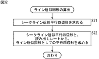
そこで、図32のフローチャートを参照して、メディア読み出しラインLrを近似するライン近似図形を特定する図形データとして、シークライン近似平行四辺形を特定するデータと、読み出しレートRrとを採用する場合の、ライン近似図形の算出方法について説明する。
【0217】
この場合、リアルタイム再生可否判定部15は、ステップS71において、シークライン近似平行四辺形を特定するデータから、シークライン近似平行四辺形を求め、ステップS72に進む。ステップS72では、リアルタイム再生可否判定部15は、シークライン近似平行四辺形と、読み出しレートRrから、ライン近似図形を求め、即ち、図29で説明したように、シークライン近似平行四辺形と同一の底辺を有し、シークライン近似平行四辺形の上底(上辺)を実質読み出し時間だけ時間方向に移動した平行四辺形を、ライン近似図形として求め、処理を終了する。
【0218】
なお、ライン近似図形は、その他、例えば、図33に示すようにして求めることが可能である。
【0219】
即ち、いま、平均再生ラインと同一の傾きを有し、メディアシークラインLsに上から接する直線#1と下から接する直線#2を考え、直線#1上の任意の1点P1の座標が(t1,d1)で表されるとともに、直線#2上の任意の1点P2の座標が(t2,d2)で表されるものとする。さらに、直線#1と#2のx切片は、それぞれb1とb2であるとする。なお、図33では、点P1(t1,d1)は、直線#1上の点となっている他、メディアシークラインLs上のシークが開始される点ともなっている。また、点P2(t2,d2)は、直線#2上の点となっている他、メディアシークラインLs上のシークが終了する点ともなっている。
【0220】
この場合、直線#1は、式y=−d1×(b1−t1)×x+d1/(b1−t1)で表され、直線#2は、式y=−d2×(b2−t2)×x+d2/(b2−t2)で表される。
【0221】
一方、無シーク読み出しラインLnsにおいて、y座標がd1またはd2の点のx座標を、それぞれdt1またはdt2とする。
【0222】
そして、点P1を、dt1だけ右方向(時間が進行する方向)に平行移動した点を、点P1’とするとともに、点P2を、dt2だけ右方向に平行移動した点を、点P2’とする。この場合、点P1’と、直線#1のx切片(b1,0)とを結んだ直線#1’は、式y=−d1×(b1−t1−dt1)×x+d1/(b1−t1−dt1)で表される。また、点P2’と、直線#2のx切片(b2,0)とを結んだ直線#2’は、式y=−d2×(b2−t2−dt2)×x+d2/(b2−t2−dt2)で表される。
【0223】
ライン近似図形は、以上のようにして求められる直線#1’および#2’、並びに、x軸、および無シーク読み出しラインLnsの終点を通るx軸に平行な直線で囲まれる平行四辺形として求めることができる。
【0224】
この場合、ライン近似図形を特定する図形データとしては、例えば、点P1,P2、直線#1(または#1’)のx切片、直線#2(または#2’)のx切片、無シーク読み出しラインLnsの終点(のx座標またはy座標のうちの少なくとも一方)、無シーク読み出しラインLnsの傾き(読み出しレートRr)を採用することができる。
【0225】
以上のように、メディア読み出しラインを近似するライン近似図形に基づき、要求再生レートでのAVデータのリアルタイム再生に必要とされる最小バッファ量と最小再生遅延時間とを算出し、最小バッファ量と最小再生遅延時間に基づき、要求再生レートでのAVデータのリアルタイム再生の可否を判定するようにしたので、要求再生レートでのリアルタイム再生に必要な最小バッファ量と最小再生遅延時間を、容易に求めることができ、さらに、要求再生レートでのリアルタイム再生の可否を、容易に判定することができる。
【0226】
次に、記録再生制御部1による上述した一連の処理は、ハードウェアにより行うこともできるし、ソフトウェアにより行うこともできる。一連の処理をソフトウェアによって行う場合には、そのソフトウェアを構成するプログラムが、汎用のコンピュータ等にインストールされる。
【0227】
そこで、図34は、上述した一連の処理を実行するプログラムがインストールされるコンピュータの一実施の形態の構成例を示している。
【0228】
プログラムは、コンピュータに内蔵されている記録媒体としてのハードディスク105やROM103に予め記録しておくことができる。
【0229】
あるいはまた、プログラムは、フレキシブルディスク、CD-ROM(Compact Disc Read Only Memory),MO(Magneto Optical)ディスク,DVD(Digital Versatile Disc)、磁気ディスク、半導体メモリなどのリムーバブル記録媒体111に、一時的あるいは永続的に格納(記録)しておくことができる。このようなリムーバブル記録媒体111は、いわゆるパッケージソフトウエアとして提供することができる。
【0230】
なお、プログラムは、上述したようなリムーバブル記録媒体111からコンピュータにインストールする他、ダウンロードサイトから、ディジタル衛星放送用の人工衛星を介して、コンピュータに無線で転送したり、LAN(Local Area Network)、インターネットといったネットワークを介して、コンピュータに有線で転送し、コンピュータでは、そのようにして転送されてくるプログラムを、通信部108で受信し、内蔵するハードディスク105にインストールすることができる。
【0231】
コンピュータは、CPU(Central Processing Unit)102を内蔵している。CPU102には、バス101を介して、入出力インタフェース110が接続されており、CPU102は、入出力インタフェース110を介して、ユーザによって、キーボードや、マウス、マイク等で構成される入力部107が操作等されることにより指令が入力されると、それにしたがって、ROM(Read Only Memory)103に格納されているプログラムを実行する。あるいは、また、CPU102は、ハードディスク105に格納されているプログラム、衛星若しくはネットワークから転送され、通信部108で受信されてハードディスク105にインストールされたプログラム、または図1のディスクドライブ2に対応するドライブ109に装着されたリムーバブル記録媒体111から読み出されてハードディスク105にインストールされたプログラムを、RAM(Random Access Memory)104にロードして実行する。これにより、CPU102は、上述したフローチャートにしたがった処理、あるいは上述したブロック図の構成により行われる処理を行う。そして、CPU102は、その処理結果を、必要に応じて、例えば、入出力インタフェース110を介して、LCD(Liquid Crystal Display)やスピーカ等で構成される出力部106から出力、あるいは、通信部108から送信、さらには、ハードディスク105に記録等させる。
【0232】
ここで、本明細書において、コンピュータに各種の処理を行わせるためのプログラムを記述する処理ステップは、必ずしもフローチャートとして記載された順序に沿って時系列に処理する必要はなく、並列的あるいは個別に実行される処理(例えば、並列処理あるいはオブジェクトによる処理)も含むものである。
【0233】
また、プログラムは、1のコンピュータにより処理されるものであっても良いし、複数のコンピュータによって分散処理されるものであっても良い。さらに、プログラムは、遠方のコンピュータに転送されて実行されるものであっても良い。
【0234】
なお、本実施の形態では、光ディスク31から読み出されたAVデータをバッファリングするバッファ19を、記録再生制御部1に設けるようにしたが、バッファ19は、記録再生制御部1ではなく、ディスクドライブ2に内蔵させることが可能である。
【0235】
また、本発明は、光ディスク31以外の、光磁気ディスクや、磁気ディスク、その他の記録媒体に記録されたデータを再生する場合にも適用可能である。
【0236】
さらに、本発明は、AVデータ以外のデータを再生する場合にも適用可能である。
【0237】
また、本実施の形態では、ディスクドライブ2において、光ディスク31から最初にデータを読み出すときに生じるシークを、メディア読み出しラインLrに考慮しなかったが、図1のディスク装置を実施するにあたっては、光ディスク31から最初にデータの読み出しが行われるときに生じるシーク(以下、適宜、先行シークという)を考慮する必要がある。具体的には、図3のステップS14において、ライン近似図形に基づいて求められた最小再生遅延時間に、先行シークのシーク時間を加算した値を、ステップS15での判定に用いる最終的な最小再生遅延時間とする必要がある。
【0238】
なお、AVデータの再生が開始される直前のディスクドライブ2のピックアップ(ヘッド)の位置が分かる場合には、その位置に基づき、シーク時間関数を用いて、先行シークのシーク時間を求めることができるが、AVデータの再生が開始される直前のディスクドライブ2のピックアップの位置を認識することができない場合には、先行シークのシーク時間としては、例えば、最大シーク時間(光ディスク31の最内周と最外周との間のシークに要する時間)などを採用することができる。
【0239】
【発明の効果】
以上の如く、本発明によれば、ユーザが要求した再生レートでのリアルタイム再生が可能であるかどうかのリアルタイム再生可否判定を、容易に行うことが可能となる。
【図面の簡単な説明】
【図1】本発明を適用したディスク装置の一実施の形態の構成例を示すブロック図である。
【図2】図形データ演算処理を説明するフローチャートである。
【図3】リアルタイム再生可否判定処理を説明するフローチャートである。
【図4】メディアアクセス情報を説明する図である。
【図5】メディア読み出しラインを示す図である。
【図6】リアルタイム再生ラインを説明する図である。
【図7】リアルタイム再生ラインを算出する処理を説明するフローチャートである。
【図8】リアルタイム再生ラインを算出する処理を説明する図である。
【図9】バッファ上限ラインを説明する図である。
【図10】バッファ上限ラインを算出する方法を説明する図である。
【図11】バッファ上限ラインを算出する処理を説明するフローチャートである。
【図12】バッファ上限ラインを算出する処理を説明する図である。
【図13】ビデオデータとオーディオデータとを並列して読み出す場合のリアルタイム再生ラインとバッファ上限ラインの算出方法を説明する図である。
【図14】メディア読み出しラインを近似するライン近似図形としてのホッケースティック形を示す図である。
【図15】要求再生レートでのリアルタイム再生の可否を、ライン近似図形を用いて行う方法を説明する図である。
【図16】ライン近似図形としてのホッケースティック形を示す図である。
【図17】ライン近似図形としての他のホッケースティック形を示す図である。
【図18】仮想再生ラインの決定方法を説明する図である。
【図19】仮想再生ラインを決定する処理を説明するフローチャートである。
【図20】仮想再生ラインを決定する処理を説明する図である。
【図21】仮想再生ラインの決定方法を説明する図である。
【図22】仮想再生ラインを決定する処理を説明するフローチャートである。
【図23】仮想再生ラインの決定方法を説明する図である。
【図24】仮想再生ラインの決定方法を説明する図である。
【図25】仮想再生ラインの決定方法を説明する図である。
【図26】仮想再生ラインの決定方法を説明する図である。
【図27】メディア読み出しラインが、無シーク読み出しラインとメディアシークラインに分離することができることを説明する図である。
【図28】メディアシークラインを近似するシークライン近似平行四辺形を示す図である。
【図29】シークライン近似平行四辺形と無シーク読み出しラインから求められるライン近似図形を示す図である。
【図30】メディア読み出しラインを、無シーク読み出しラインとメディアシークラインに分離した場合の、図形データの演算処理を説明するフローチャートである。
【図31】メディア読み出しラインを、無シーク読み出しラインとメディアシークラインに分離する方法を説明する図である。
【図32】シークライン近似平行四辺形と無シーク読み出しラインから、ライン近似図形を求める処理を説明するフローチャートである。
【図33】シークライン近似平行四辺形と無シーク読み出しラインから、ライン近似図形を求める方法を説明する図である。
【図34】本発明を適用したコンピュータの一実施の形態の構成例を示すブロック図である。
【符号の説明】
1 記録再生制御部, 2 ディスクドライブ, 11 システム制御部, 12 入力部, 13 図形データ演算部13 図形データ記憶部, 15 リアルタイム再生可否判定部, 16 再生条件記憶部, 17 読み書き制御部, 18 データ記憶部, 19 バッファ, 20 出力部, 31 光ディスク, 101 バス, 102 CPU, 103 ROM, 104 RAM, 105 ハードディスク, 106 出力部, 107 入力部, 108 通信部, 109 ドライブ, 110 入出力インタフェース, 111 リムーバブル記録媒体[0001]
BACKGROUND OF THE INVENTION
The present invention relates to an information processing apparatus, an information processing method, and a program, and in particular, easily performs real-time playback availability determination as to whether or not data recorded on a recording medium such as an optical disk can be played back in real time. The present invention relates to an information processing apparatus, an information processing method, and a program.
[0002]
[Prior art]
For example, when AV (Audio Visual) data such as video data and audio data is repeatedly written and erased on a recording medium such as an optical disk, AV data to be continuously reproduced is divided on the optical disk. It will be recorded.
[0003]
In addition, such division of AV data to be reproduced continuously on the optical disc occurs, for example, when the optical disc has a defect or when so-called nondestructive editing is performed.
[0004]
Here, nondestructive editing means, for example, setting only so-called editing points (IN point, OUT point) for AV data as material data recorded on an optical disc or the like, and not editing the material data itself ( It is an editing method that does not destroy. In nondestructive editing, for example, a list of editing points set at the time of editing, called a playlist, is created. The edited result is reproduced according to the playlist. In other words, the reproduction of the nondestructive editing result is performed by reproducing the material data recorded on the optical disc in accordance with the editing points described in the playlist. As described above, the reproduction of the nondestructive editing result is performed by reproducing the material data recorded on the optical disc in accordance with the editing points described in the playlist. As a result, the non-destructive editing result is reproduced continuously. This is equivalent to a state in which a series of power AV data is divided and recorded on an optical disc.
[0005]
As described above, when reproducing AV data that is divided and recorded on an optical disk, the AV data to be reproduced next to the AV data recorded in a certain recording area on the optical disk is stored in another remote recording area. It may be recorded. In this case, after reading AV data recorded in a certain recording area of the optical disk, it is necessary to read AV data recorded in another remote recording area, and from one recording area to another remote recording area. A seek occurs.
[0006]
If the seek time required for this seek is long, the AV data to be reproduced may not be read in time for the reproduction time, and the reproduction may be interrupted, that is, the AV data may not be reproduced in real time. .
[0007]
Specifically, for example, AV data recorded on an optical disk is reproduced by reading AV data recorded on the optical disk, buffering it in a predetermined buffer, and then processing the AV data buffered in the buffer. Is done by.
[0008]
In this case, generally, the read rate of AV data from the optical disc is set higher than the playback rate of AV data, and thus the rate of AV data input to the buffer is higher than the rate of AV data output from the buffer. Be bigger than the rate. Therefore, basically, AV data read from the optical disc is gradually accumulated in the buffer. However, when a seek occurs, AV data is not read from the optical disk during that time, so AV data is only output from the buffer for playback, and the amount of AV data in the buffer decreases. I will do it. Then, when the AV data in the buffer is exhausted, the seek is completed, and if the reading of the AV data from the optical disk is not reproduced, the buffer underflows and reproduction is interrupted.
[0009]
Therefore, if the amount of AV data in the buffer before seeking is sufficient, it is possible to prevent playback from being interrupted by seeking. The amount of AV data in the buffer increases if AV data is continuously read from the optical disc, and decreases if no AV data is read (when a seek occurs). In order to make the data amount of AV data sufficient, it is sufficient to continuously read AV data from the optical disc by a sufficient amount before seeking. In order to continuously read AV data from the optical disk by a sufficient amount of data, it is only necessary that AV data is continuously recorded in a continuous recording area of a certain size on the optical disk.
[0010]
Therefore, for example, in
[0011]
[Patent Document 1]
Japanese Patent Laid-Open No. 11-98447.
[0012]
[Problems to be solved by the invention]
By the way, even when AV data is continuously recorded in a certain continuous recording area of the optical disk, real-time reproduction cannot be performed by seek depending on the disk device that reproduces the optical disk. There is.
[0013]
That is, for example, the buffer size, which is the storage capacity of the buffer for buffering AV data read from the optical disc, differs depending on the disc device, and even if a disc device with a large buffer size can perform real-time playback, Real-time playback may not be possible with a disk device having a small buffer size.
[0014]
AV data may be required to be played at high speed in addition to normal playback. Even if real-time playback can be performed during normal playback, real-time playback (here, Real-time reproduction means that reproduction at a required reproduction rate is performed without interruption).
[0015]
Then, in the disk device, after the reproduction of AV data at the reproduction rate requested by the user is started, the reproduction is interrupted, which makes the user feel uncomfortable.
[0016]
Therefore, before starting playback of AV data, it is requested to determine whether or not real-time playback is possible at the playback rate requested by the user and to notify the user of the determination result. .
[0017]
In order to determine whether or not this real-time reproduction is possible, it is necessary to actually read AV data recorded on the optical disc and check whether the reading is in time for reproduction at a reproduction rate requested by the user.
[0018]
However, it is time consuming and cumbersome to actually read AV data recorded on the optical disc and determine whether or not real-time playback is possible every time the user instructs playback.
[0019]
The present invention has been made in view of such a situation, and makes it possible to easily determine whether or not real-time playback is possible at a playback rate requested by a user. It is.
[0020]
[Means for Solving the Problems]
The information processing apparatus according to the present invention includes graphic data acquisition means for acquiring graphic data for specifying a line approximate graphic that approximates a medium read line that represents a transition of a read data amount when data is read from a recording medium, and specified by graphic data The minimum buffer size, which is the minimum buffer size required for real-time playback of data at the required playback rate, and the time from the start of data read to the start of data playback Calculation means for calculating a minimum reproduction delay time, which is the minimum value of the reproduction delay time, and determination means for determining whether or not data can be reproduced in real time at the requested reproduction rate based on the minimum buffer amount and the minimum reproduction delay time. It is characterized by that.
[0021]
An information processing method according to the present invention includes a graphic data acquisition step for acquiring graphic data for specifying a line approximate graphic that approximates a media read line that represents a transition of a read data amount when reading data from a recording medium, and a graphic data acquisition step. The minimum buffer size, which is the minimum buffer size required for real-time playback of data at the required playback rate, and the time from the start of data read to the start of data playback A calculation step for calculating a minimum reproduction delay time which is a minimum value of the reproduction delay time, and a determination step for determining whether or not real-time reproduction of data at the requested reproduction rate is possible based on the minimum buffer amount and the minimum reproduction delay time. It is characterized by that.
[0022]
The program according to the present invention is specified by a graphic data acquisition step for acquiring graphic data for specifying a line approximate graphic that approximates a media read line that represents a transition of a read data amount when data is read from a recording medium, and the graphic data. Based on the line approximation figure, the minimum buffer size, which is the minimum buffer size required for real-time data playback at the required playback rate, and the playback delay from the start of data read to the start of data playback A calculation step for calculating a minimum reproduction delay time that is a minimum value of time, and a determination step for determining whether real-time reproduction of data at a requested reproduction rate is possible based on the minimum buffer amount and the minimum reproduction delay time. Features.
[0023]
In the information processing apparatus, the information processing method, and the program according to the present invention, graphic data specifying a line approximate graphic that approximates a media read line that represents a change in the amount of read data when data is read from a recording medium is acquired. Based on the line approximation figure specified by the figure data, the minimum buffer amount, which is the minimum buffer size required for real-time reproduction of data at the required reproduction rate, and data reproduction from the start of data reading The minimum reproduction delay time, which is the minimum value of the reproduction delay time until the start of, is calculated, and whether or not data can be reproduced in real time at the requested reproduction rate is determined based on the minimum buffer amount and the minimum reproduction delay time. .
[0024]
DETAILED DESCRIPTION OF THE INVENTION
FIG. 1 shows a configuration example of an embodiment of a disk device to which the present invention is applied.
[0025]
The disk device includes a recording /
[0026]
That is, the recording / reproducing
[0027]
Specifically, in the recording /
[0028]
The
[0029]
Here, examples of commands and information input by the user by operating the
[0030]
The graphic
[0031]
The real-time reproduction
[0032]
The reproduction
[0033]
Here, the reproduction request rate is supplied from the
[0034]
The allowable reproduction delay time is the time allowed by the user as the reproduction delay time from the start of reading of data from the optical disc 31 to the start of reproduction of the data, or is allowed in the disc device. It is time. The allowable buffer amount is a size allowed by the user or a size allowed in the disk device as a buffer size (total storage capacity) of the
[0035]
The seek time function is a seek time required to perform a seek from a seek source logical block that is a logical block of the optical disc 31 to a seek destination logical block that is another logical block, for example, a seek source logical block And a logical block number (LBN (Logical Block Number)) of the logical block of the seek destination as an argument. That is, for example, the recording area of the optical disc 31 is divided into logical blocks of a predetermined size (physical blocks assigned to), and each logical block has an LBN as a sequential number in the read / write order with respect to the optical disc 31. It is attached. According to the seek time function, when two LBNs are given as arguments, one of the two logical blocks specified by the two LBNs is set as a seek source logical block, and the other is a seek destination logical block. The seek time required for seeking from the seek source logical block to the seek destination logical block can be obtained. Here, the seek time obtained by the seek time function is, for example, the worst value of the seek time required to seek from the seek-source logical block to the seek-destination logical block, and includes the time to wait for rotation of the optical disc 31. . Further, the seek time function is stored in, for example, the disk drive 2 and is supplied from the disk drive 2 to the reproduction
[0036]
The media access information represents the order in which data recorded on the optical disc 31 is read. That is, on the optical disc 31, as described above, a certain series of data is not necessarily recorded in one continuous recording area, but may be divided and recorded in a plurality of continuous recording areas. is there. In this way, the media access information represents in what order to access a recording area in which data is recorded by being divided on the optical disc 31. The media access information is obtained by the
[0037]
The read /
[0038]
The
[0039]
An optical disk 31 can be easily attached to and detached from the disk drive 2. The disk drive 2 includes, for example, one pickup (not shown), and writes data to the optical disk 31 and reads data from the optical disk 31 under the control of the read /
[0040]
In the following, it is assumed that AV data that is particularly required to be reproduced in real time is recorded on the optical disc 31.
[0041]
In the disk device configured as described above, for example, when the user instructs the reproduction of the optical disk 31 by operating the
[0042]
That is, in this case, the read /
[0043]
In the above reproduction processing, AV data read from the optical disk 31 is input to the
[0044]
In the disk apparatus of FIG. 1, as described above, in addition to performing the reproduction process for reproducing the AV data recorded on the optical disk 31, whether or not the AV data can be reproduced in real time in the reproduction process is determined. Judgment processing is performed. Also, in the real-time playback availability determination process, AV data can be played back in real time based on a line approximation figure that approximates the media read line that represents the transition of the read data amount when reading data from the optical disc 31 in the disk drive 2. In order to determine whether or not, the disk apparatus of FIG. 1 also performs graphic data calculation processing for obtaining graphic data for specifying the line approximate graphic used in the real-time reproduction availability determination processing.
[0045]
First, the graphic data calculation process will be described with reference to the flowchart of FIG.
[0046]
The graphic data calculation process is started, for example, when the optical disk 31 is loaded in the disk drive 2 or immediately after AV data is recorded on the optical disk 31.
[0047]
That is, in the graphic data calculation process, in step S1, the
[0048]
Then, the process proceeds to step S2, and the graphic
[0049]
In the graphic data calculation process described above, after the graphic data is obtained, the media read line stored in the reproduction
[0050]
Next, the real-time reproduction permission / inhibition determination process will be described with reference to the flowchart of FIG.
[0051]
The real-time playability determination process is performed, for example, immediately after the graphic data calculation process of FIG. 2 or when the user operates the
[0052]
That is, in the real-time reproduction availability determination process, in step S11, the real-time reproduction
[0053]
Here, in the disk device of FIG. 1, for example, the graphic data obtained in the graphic data calculation process of FIG. When graphic data is recorded on the optical disc 31, the real-time reproduction
[0054]
After the graphic data is acquired in step S11, the process proceeds to step S12, and the real-time playback
[0055]
Here, for example, a default value (for example, a playback rate corresponding to 1 × speed playback) or an input from the
[0056]
In step S14, the real-time
[0057]
In step S15, the real-time reproduction
[0058]
If it is determined in step S15 that real-time playback at the required playback rate is possible, that is, the allowable buffer amount is equal to or greater than the minimum buffer amount and the allowable playback delay time is equal to or greater than the minimum playback delay time (buffer When the buffer size of 19 is allowed to be greater than the minimum buffer amount and the playback delay time is allowed to be longer than the minimum playback delay time), the process proceeds to step S16, and the real-time playback
[0059]
In this case, in the disk device of FIG. 1, the AV data recorded on the optical disk 31 is reproduced in real time at the requested reproduction rate as described above.
[0060]
On the other hand, if it is determined in step S15 that real-time reproduction at the requested reproduction rate is not possible, that is, whether the allowable buffer amount is less than the minimum buffer amount (the
[0061]
That is, in this case, the user is notified that the AV data recorded on the optical disk 31 cannot be reproduced in real time at the requested reproduction rate in the disk device of FIG.
[0062]
In step S17, when the user is informed that AV data cannot be reproduced in real time, the user sets the allowable buffer amount or the allowable reproduction delay time to a large value by operating the
[0063]
In step S17, it is possible to notify that the AV data cannot be reproduced in real time and to request the
[0064]
Here, compiling means that AV data that is continuously played out of AV data recorded on the optical disc 31 is rearranged in, for example, a certain continuous free space on the optical disc 31. . As a result of this compilation, the continuously reproduced AV data is recorded in a recording area that is continuous to some extent on the optical disc 31, and therefore, at least AV data continuously from the continuous recording area. Can be read and no seek occurs during that time. Therefore, according to the compilation, it is possible to prevent the AV data from being read out by the time to be reproduced due to frequent seeks, and the reproduction from being interrupted.
[0065]
Next, graphic data calculation processing and real-time reproduction availability determination processing performed in the disk apparatus of FIG. 1 will be further described.
[0066]
In the disc apparatus of FIG. 1, the buffer size of the
[0067]
That is, when the buffer size of the
[0068]
Therefore, when determining whether or not real-time reproduction is possible, it is necessary to clarify under what conditions (reproduction conditions) the reproduction of AV data is performed. As described above, the playback conditions include media access information, read rate, seek time (seek time function), required playback rate, allowable buffer amount, and allowable playback delay time.
[0069]
Note that the media access information depends on AV data recorded on the optical disc 31 (how the series of AV data is recorded on the optical disc 31), and depends on the read rate and seek time (seek time function). Depends on the specifications (or performance) of the disk drive 2. The required playback rate depends on the operation of the
[0070]
In the real-time reproduction availability determination process, as described with reference to FIG. 3, the minimum buffer amount that is the minimum buffer size required for real-time reproduction of AV data at the requested reproduction rate, and the AV data as the requested reproduction rate. The minimum playback delay time, which is the minimum playback delay time required for real-time playback, is determined.If the allowable buffer amount is greater than or equal to the minimum buffer amount and the allowable playback delay time is greater than or equal to the minimum playback delay time, real time It is determined that playback is possible.
[0071]
Therefore, the problem of determining whether or not real-time reproduction is possible can be reduced to the problem of deriving the minimum buffer amount and the minimum reproduction delay time.
[0072]
The minimum buffer amount and the minimum reproduction delay time can be obtained graphically from a media read line that represents the transition of the read data amount when reading data from the optical disc 31 in the disc drive 2. Therefore, in order to obtain the minimum buffer amount and the minimum reproduction delay time, it is first necessary to obtain a media read line.
[0073]
The media read line can be obtained from the media access information.
[0074]
That is, continuous writing and deletion of data on the optical disc 31 and the presence of defects in the recording area of the optical disc 31 cause a continuous free area to be divided on the optical disc 31. When a series of AV data (stream) is recorded on the optical disc 31 in which such continuous free areas are divided, the AV data is stored in the divided free areas. Arranged up to the size of the area. Now, assuming that a continuous recording area in which continuous AV data is recorded on the optical disc 31 is called an extent, and media access information is represented by an extent, the media access information is, for example, shown in FIG. As shown in FIG.
[0075]
Here, in FIG. 4, one rectangle represents an extent. In FIG. 4, the left end and right end of the rectangle representing the extent indicate the LBN (first LBN) of the first logical block and the LBN (end LBN) of the last logical block, respectively. . In FIG. 4, the length of the rectangle representing the extent in the left-right direction corresponds to the size of the extent.
[0076]
The media access information shown in FIG. 4 is configured by arranging extents (representing rectangles) in the order of playback from the left to the right. Accordingly, the media access information in FIG. 4 represents that the
[0077]
In FIG. 4,
[0078]
Since an extent is a continuous recording area in which continuous AV data is recorded, there is a discontinuity between an extent in which certain AV data is arranged and an extent in which AV data to be reproduced next is arranged. ing. Accordingly, when the AV data is read over the two extents in the disk drive 2, a seek occurs.
[0079]
That is, in FIG. 4, for example, after reading
[0080]
As described above, this seek time can be obtained by a seek time function using the LBN of the seek source logical block and the LBN of the seek destination logical block.
[0081]
In the disk drive 2, the AV data of the extent is read at the read rate.
[0082]
From the above, the time transition of the media read line when reading the
[0083]
That is, FIG. 5 shows the media read line L when reading the
[0084]
In FIG. 5, the media read line LrIs the data read rate R by the disk drive 2 when the AV data of the
[0085]
In the disk drive 2, a seek also occurs immediately before the start of reading the first extent, that is, reading the
[0086]
Next, FIG. 6 shows a real-time reproduction line L.pIs shown. In FIG. 6, the real-time playback line LpIn addition, the buffer upper limit line LupIs also shown, but this buffer upper limit line LupWill be described later.
[0087]
AV data read from the optical disc 31 is a media read line L.rIn order to determine whether or not the AV data can be played back in real time, the real-time playback line LpNeed to be introduced.
[0088]
Real-time playback line LpRepresents time transition of the total amount of AV data output from the
[0089]
For example, if the playback rate when playing a series of AV data is constant, the real-time playback line LpAs shown in FIG. 6, the slope is a straight line of the reproduction rate.
[0090]
If the start time of reading AV data from the optical disk 31 is 0, the real-time playback line LpMore precisely, it becomes 0 until the AV data is output from the
[0091]
In FIG. 6 (the same applies to the above-described FIG. 5 and the drawings to be described later), the horizontal axis (x-axis) is time, and the vertical axis (y-axis) is the amount of data (total amount). In this case, the real-time playback line LpIs the time indicated by the point (x-intercept) that intersects the x-axis representing the time as the reproduction delay time.
[0092]
As described above, the real-time playback line LpRepresents the amount of AV data output from the
[0093]
Therefore, in order to guarantee real-time playback of AV data, the real-time playback line LpHowever, it is desirable to be located in the right direction as much as possible.
[0094]
However, the real-time playback line LpThe playback delay time becomes larger as the position of is more rightward.
[0095]
Therefore, in order to shorten the reproduction delay time as much as possible and guarantee real-time reproduction, the real-time reproduction line LpIs the media read line LrMust be in the leftmost position, not exceeding.
[0096]
That is, as shown in FIG.pIs the media read line LrOn the other hand, when one or more points are in contact from the bottom, the reproduction delay time can be minimized and real-time reproduction can be performed.
[0097]
Real-time playback line LpIs the media read line LrOn the other hand, the reproduction delay time T in the case of touching at one or more points from the bottom is the minimum reproduction delay time T which is the minimum reproduction delay time required for real-time reproduction.wIt is.
[0098]
Here, real-time playback line LpIs the media read line LrOn the other hand, one or more points in contact with the bottom are hereinafter appropriately referred to as rate-limiting points.
[0099]
If the data amount per frame of AV data is fixed, the real-time playback line LpStrictly speaking, it changes stepwise in units of time corresponding to frames.
[0100]
Further, when the AV data recorded on the optical disc 31 is, for example, variable length data, the real-time playback line LpNeeds to be drawn on the basis of the reproduction time at which AV data obtained by decoding variable length data is reproduced. Further, when AV data having a certain rate to be encoded by, for example, the MPEG (Moving Picture Experts Group) method is handled, for example, the read /
[0101]
The graphic
[0102]
Therefore, referring to the flowchart of FIG.pA real-time reproduction line calculation process for obtaining the above will be described.
[0103]
In the real-time reproduction line calculation process, first, in step S21, the graphic
[0104]
The figure
[0105]
Here, the media read line LrThe point immediately after the end of the seek is also the point at which reading of the AV data of the extent from the optical disc 31 is started, and is hereinafter referred to as a read start point as appropriate.
[0106]
Note that the reading start point (Xi, YiX-coordinate XiRepresents time and y-coordinate YiRepresents the total amount of data. X coordinate XiAnd y coordinate YiThe suffix i is the read start point (Xi, Yi) Represents what number from
[0107]
In step S22, the graphic
[0108]
Here, the straight line L (i) as a candidate for the real-time reproduction line can be expressed by the following equation, for example.
[0109]
y = Rpx + Yi-RpXi
[0110]
In step S24, the graphic
[0111]
Here, as described above, the reproduction delay time is represented by the x-intercept of the real-time reproduction line. Accordingly, the reproduction delay time T (i) for the real-time reproduction line candidate L (i) can be obtained by the following equation, for example.
[0112]
T (i) =-(Yi-RpXi) / Rp
[0113]
In step S25, the graphic
[0114]
According to the above real-time reproduction line calculation processing, the expression y = 0 from
[0115]
When there are a plurality of suffixes i that maximize the reproduction delay time T (i), any of the suffixes i may be used as the suffix I that maximizes the reproduction delay time T (i). .
[0116]
Next, AV data is read from the optical disc 31 to the media read line L.rIn order to determine whether or not the AV data can be played back in real time, the real-time playback line LpIn addition, the buffer upper limit line LupNeed to be introduced.
[0117]
9 shows the buffer upper limit line L.upIs shown.
[0118]
Buffer upper limit line LupRepresents the time transition of the total amount of the upper limit of the amount of data that can be stored in the
[0119]
As described above, the media read line LrRepresents the amount of AV data read from the optical disc 31 and buffered in the
[0120]
Buffer upper limit line LupAnd real-time playback line LpDifference (buffer upper limit line LupAnd real-time playback line Lp(Distance in the y-axis direction (vertical direction) between the two) represents the buffer size required for the
[0121]
From the above, in order to minimize the buffer size required for the
[0122]
Buffer upper limit line LupIs the media read line Lr, The buffer size of the buffer 19 (the buffer upper limit line LupAnd real-time playback line LpIs the minimum buffer amount B that is the
[0123]
This minimum buffer amount BminCan be reduced by waiting for rotation in the disk drive 2. However, waiting for rotation is the media read line LrIt can only be performed at the point on the right side of the rate limiting point.
[0124]
Here, the buffer upper limit line LupIs the media read line LrHereinafter, one or more points that are in contact with each other from above are referred to as minimum buffer points as appropriate.
[0125]
The graphic
[0126]
Therefore, referring to the flowchart of FIG.upA buffer upper limit line calculation process for obtaining the above will be described.
[0127]
In the buffer upper limit line calculation process, first, in step S31, the graphic
[0128]
In step S33, the graphic
[0129]
Here, as described above, the real-time playback line LpIs the buffer upper limit line LupTherefore, the buffer upper limit line calculation process is performed in the real-time reproduction line L in the real-time reproduction line calculation process of FIG.pNeeds to be done after asked.
[0130]
In the real-time reproduction line calculation process of FIG. 7, as described above, the expression y = 0 from
[0131]
In step S33, the graphic
[0132]
In step S34, the media read line LrWhen it is determined that none of the second and subsequent seek start points above are positioned above the candidate line, that is, as shown in FIG.rWhen all the second and subsequent seek start points above are located below or in contact with the candidate line (the candidate line is the media read line LrIf not, the graphic
[0133]
In step S34, the media read line LrWhen it is determined that there is one in the second and subsequent seek start points located above the candidate line, that is, the media read line LrIf the coordinates of the second and subsequent seek start points above are (X, Y), the formula Y> RpX + YI-RpXIIf there is a seek start point (X, Y) that satisfies + D, the process proceeds to step S36, where the graphic
[0134]
In step S37, the
[0135]
According to the above buffer upper limit line calculation processing, the buffer upper limit line LupAlong with the minimum buffer amount BminIs required.
[0136]
Next, on the optical disc 31, a file of only single AV data of only video data or audio data is recorded. When reproducing the AV data, that is, only video data or audio data, Using the above method as it is, the real-time playback line LpAnd minimum playback delay time Tw, And buffer upper limit line LupAnd minimum buffer size BminHowever, for example, when video data and audio data recorded as separate files on the optical disc 31 are reproduced as AV data of one file as a whole, real-time reproduction is performed as follows. Line LpAnd minimum playback delay time Tw, And buffer upper limit line LupAnd minimum buffer size BminIt is necessary to ask.
[0137]
That is, even if a plurality of data such as video data and audio data are recorded as separate files on the optical disc 31, the files of the video data and the audio data can be regarded as one AV data file when played back. The list is described in a file called a VFL (Virtual File List) file, and according to the VFL file, for example, there is a method of simultaneously reproducing video data and accompanying audio data.
[0138]
In this case, it is necessary to read video data and audio data from the optical disc 31 in parallel. Therefore, first, as described above, for the video data and the audio data, as shown in FIG.rAnd ALrEach, and further, real-time playback line VLpAnd ALpFor each. Note that even if the video data and the audio data are read out in parallel from the optical disc 31, actually, as shown in FIG. 13, the video data and the audio data are seeked as necessary in the order of reproduction, for example. However, it is read from the optical disc 31 in a time division manner.
[0139]
Real-time playback line VL for video data and audio datapAnd ALpAre obtained, and then the video data real-time playback line VLpThe minimum playback delay time VT obtained fromwAnd audio data real-time playback line ALpPlayback delay time AT obtained fromwIs different from the video data real-time playback line VLpAnd audio data real-time playback line ALpOf these, the smaller one of the minimum reproduction delay times is shifted to the right so as to match the larger one. In general, the minimum reproduction delay time VT of video datawIs the minimum audio data playback delay time ATwAudio data minimum playback delay time ATwIs the minimum playback delay time VT of the video data.wThe audio data real-time playback line ALpIs shifted to the right, so that the real-time playback line ALp'.
[0140]
And the real-time playback line VL of the video data obtained as described abovepAs shown in FIGS. 9 to 12, the video data buffer upper limit line VL is used.upAudio data real-time playback line ALp′, The audio data buffer upper limit line AL as described with reference to FIGS.upAsk for.
[0141]
Here, it is assumed that an independent buffer is employed as the
[0142]
For files consisting of many extents, the minimum buffer amount B at the standard playback rateminAnd minimum playback delay time TwSince it may take time to calculate the minimum buffer amount B at the reference playback rate.minAnd minimum playback delay time TwCan be obtained when a file is created on the optical disc 31, and can be referred to immediately when a real-time reproduction permission determination is made. Note that the minimum buffer amount B at the reference playback rate obtained when the file was createdminAnd minimum playback delay time TwFor example, if there is an extended attribute file in which an entry (file entry) of the file or various attributes of the file exists, it can be described in the extended attribute file.
[0143]
By the way, in the above case, the real-time reproduction line LpThe reference playback rate R, which is the slope ofpIs the minimum buffer amount B as the playback rate when performing 1 × speed playback.minAnd minimum playback delay time TwTherefore, the requested playback rate input by the user operating the
[0144]
On the other hand, the requested playback rate is the reference playback rate RpThe real-time playback line L having the required playback rate as a slope.pAnd buffer upper limit line LupAnd the minimum buffer amount B for the requested playback rate.minAnd minimum playback delay time TwIf the allowable buffer amount and the allowable reproduction delay time are not compared with each other, it is difficult to determine whether real-time reproduction at the requested reproduction rate is possible or not, which is troublesome. Further, a real-time playback line L having the required playback rate as a slope.pAnd buffer upper limit line LupTo obtain the media read line LrTherefore, every time the requested playback rate is changed, the media read line LrIs required. For this reason, the media read line LrHowever, every time the required playback rate is changed, it must be obtained again or stored, which is troublesome.
[0145]
Therefore, in the disk apparatus of FIG. 1, it is possible to easily determine whether or not real-time reproduction at the requested reproduction rate is possible as follows.
[0146]
That is, the media read line LrAs shown in FIG. 14, the reference playback rate RpThe minimum playback delay time TwReal-time playback line LpAnd the minimum buffer amount BminBuffer upper limit line L givingupIt is included in the range between. So now, the real-time playback line LpAnd buffer upper limit line LupFurther, the reading end point (media reading line L) at which the reading of AV data from the y-axis and optical disc 31 is completed.rFrom the shape of the outer shape (shaded portion in FIG. 14) surrounded by a straight line parallel to the x-axis passing through the last upper point (the last point in time), a hockey stick shape This hockey stick type is called a media read line LrIt can be said that the figure is an approximation.
[0147]
The hockey stick type is, for example, the reference playback rate Rp, Its standard playback rate RpMinimum playback delay time TwAnd minimum buffer size BminIt can be specified by the reading end point. Therefore, the graphic
[0148]
The real-time
[0149]
That is, in order to guarantee real-time playback at the required playback rate, the real-time playback line at the required playback rate is changed to the media read line LrMust not exceed.
[0150]
On the other hand, the hockey stick type line approximate figure calculated for the reference playback rate is the media read line LrTherefore, if the real-time playback line at the required playback rate is at a position below or in contact with the approximate figure of the hockey stick type line obtained for the reference playback rate, real-time playback at the required playback rate Line is media read line LrIs not exceeded.
[0151]
Therefore, in order to guarantee real-time playback at the required playback rate, the real-time playback line at the required playback rate is lower than the hockey stick type line approximation figure obtained for the reference playback rate, as shown in FIG. It must be drawn at a position or a contact position (hereinafter referred to as a position below a line figure as appropriate).
[0152]
Such a real-time playback line at the required playback rate is, for example, a straight line that exists at a position below the line graphic and is in contact with one or more points of the line graphic and has an inclination of the required playback rate (hereinafter referred to as appropriate). (Referred to as a regeneration request straight line), and the x intercept of the regeneration request straight line is calculated. That is, in this case, as shown in FIG. 15, the real-time playback line at the required playback rate is represented by a straight line of the equation y = 0 from
[0153]
Further, in this case, as shown in FIG. 15, the x-intercept of the real-time reproduction line (reproduction request straight line) at the required reproduction rate becomes a value approximating the minimum reproduction delay time at the reproduction required rate, and at the required reproduction rate. Buffer upper limit line L constituting a hockey stick type line approximate figure from a real-time playback lineupThe maximum value of the vertical distance up to is a value that approximates the minimum buffer amount at the reproduction request rate.
[0154]
In this way, the minimum reproduction delay time (approximate value) and the minimum buffer amount (approximate value) at the reproduction request rate are obtained and compared with the allowable buffer amount and the allowable reproduction delay time, respectively. It is possible to easily determine whether or not real-time reproduction is possible.
[0155]
In the embodiment of FIG. 15, the requested playback rate is the reference playback rate R.pIt has become twice.
[0156]
Here, hereinafter, the reference playback rate R is appropriately selected.pReal-time playback line Lp, Buffer upper limit line Lup, Minimum playback delay time Tw, Minimum buffer amount BminRespectively, the reference real-time playback line Lp, Reference buffer upper limit line Lup, Reference minimum playback delay time Tw, Reference minimum buffer amount BminThat's it.
[0157]
As described above, the reference playback rate Rp, Reference minimum playback delay time Tw, Reference minimum buffer amount BminIf the read end point is stored as graphic data in the graphic
[0158]
In order to guarantee real-time playback at the required playback rate, the real-time playback line at the required playback rate is changed to the media read line LrMedia read line LrHowever, it should not exceed the buffer limit line at the required playback rate. However, the media read line LrHowever, the case where the buffer upper limit line at the required reproduction rate is exceeded, that is, the case where the
[0159]
By the way, in the above case, when the hockey stick type is obtained, the playback rate corresponding to the 1 × speed playback is used as the reference playback rate. However, if the hockey stick type is known, the minimum playback at the required playback rate is achieved. Since the delay time and the minimum buffer amount can be obtained, it is not always necessary to use a playback rate corresponding to 1 × speed playback as the reference playback rate. Rather, by using a playback rate corresponding to 1 × playback as the reference playback rate, the media read line LrA hockey stick shape that does not approximate with high accuracy may be obtained.
[0160]
That is, the media read line LrHowever, for example, as shown in FIG. 16, a long-term seek is performed shortly after the start of reading AV data from the optical disc 31, and thereafter, the AV data is continuously read without performing a seek. If the playback rate corresponding to 1 × playback is used as the reference playback rate, the media read line LrAs a line approximation figure that approximates, a hockey stick shape having a wide width may be obtained.
[0161]
In this case, the real-time reproduction line (reproduction request straight line) at the required reproduction rate larger than the reference reproduction rate has a large x intercept as shown in FIG. Since the x intercept of the real-time playback line at the required playback rate represents the minimum playback delay time at the playback required rate, in this case, the minimum playback delay time (approximate value) at the playback required rate is originally required. A value much larger than the true value of the minimum reproduction delay time is obtained. Further, when the x intercept of the real-time reproduction line at the required reproduction rate becomes large, the real-time reproduction line and the reference buffer upper limit line L that constitutes the hockey stick type line approximate figureupThe minimum buffer amount (approximate value) at the playback request rate expressed by the vertical distance from the point is also large, and a value that is much larger than the true value of the minimum buffer amount that is originally required can be obtained. become.
[0162]
On the other hand, regardless of whether playback at that playback rate is possible or whether playback can be performed at that playback rate, the media read line L is assumed by assuming a certain virtual playback rate.rCan be obtained as a hockey stick shape as a line approximation figure that approximates with higher accuracy.
[0163]
So now the media read line LrAssuming that a virtual reproduction rate that can obtain a line approximation figure that approximates with higher accuracy is called a virtual reproduction rate, this virtual reproduction rate can be adopted as the reference reproduction rate.
[0164]
According to the line approximation figure obtained by using the virtual reproduction rate, as shown in FIG.rCan be approximated more accurately. Then, using such a line approximate figure, the real-time playback line at the required playback rate is obtained, and further, the minimum playback delay time and the minimum buffer amount at the playback required rate are obtained, so that each value is originally necessary. Thus, a value close to the true value of the minimum reproduction delay time and the minimum buffer amount is obtained.
[0165]
16 and 17 show the same media read line LrAs a reference playback rate, a playback rate corresponding to 1 × playback and a virtual playback rate are used to obtain a hockey stick shape as a line approximate figure, and further, a minimum playback delay time and a minimum buffer at the playback request rate As shown in FIG. 16 and FIG. 17, the case where the hockey stick shape is obtained using the virtual reproduction rate (FIG. 17) is shown. Smaller values are obtained as the minimum reproduction delay time and the minimum buffer amount at the reproduction request rate than when the hockey stick type is obtained using the reproduction rate corresponding to (FIG. 16).
[0166]
Next, when a hockey stick type is obtained using the virtual reproduction rate as a reference reproduction rate, there is a problem as to what reproduction rate the virtual reproduction rate is used.
[0167]
Therefore, the virtual reproduction rate is, for example, as shown in FIG.minThe value can draw a real-time playback line so that becomes smaller.
[0168]
That is, if the real-time playback line at the virtual playback rate is called a virtual playback line, the virtual playback line is the media read line LrSince it is only necessary to draw at least one of the points so as to be in contact with each other from below, there are innumerable straight lines that are candidates for virtual reproduction lines. Therefore, a virtual reproduction line that minimizes the minimum buffer amount among such countless candidates can be employed.
[0169]
Specifically, for example, as shown in FIG. 18, a virtual reproduction line candidate L having a small x-intercept and a small inclination is used.p# 1, virtual reproduction line candidate L with large x-intercept and inclinationpWhen considering # 2, a virtual reproduction line candidate L having a small x-interceptp# 1 minimum playback delay time Tw# 1 is a virtual reproduction line candidate L with a large x-interceptp# 2 minimum playback delay time TwIt becomes smaller than # 2.
[0170]
On the other hand, the virtual playback line and the media read line LrMinimum buffer amount B expressed by the maximum distance in the vertical directionminIs a virtual reproduction line candidate L with a small x-intercept and inclination.p# 1 minimum buffer size BminFrom # 1, a virtual reproduction line candidate L having a large x-intercept and inclinationp# 2 minimum buffer size Bmin# 2 is smaller.
[0171]
Therefore, the minimum buffer amount BminWhen the virtual reproduction line is obtained on the basis that the value is smaller, the virtual reproduction line candidate Lp# 2 is determined as the virtual reproduction line, and the inclination is obtained as the virtual reproduction rate. The minimum playback delay time TwWhen the virtual reproduction line is obtained on the basis that the length is short, the virtual reproduction line candidate Lp# 1 is determined as the virtual reproduction line.
[0172]
As described above, when the hockey tick shape is obtained using the virtual reproduction rate as the reference reproduction rate, the graphic
[0173]
A virtual reproduction line determination process for determining a virtual reproduction line will be described with reference to the flowchart of FIG.
[0174]
Media read line L nowrThe coordinates of the i-th reading start point above are (Xi, Yi), The graphic
[0175]
In step S42, the graphic
[0176]
Thereafter, the process proceeds to step S43, and the graphic
[0177]
As described above, in step S43, after the respective minimum buffer amounts are obtained for all the candidates for the virtual reproduction line that is the straight line selected in step S42, the process proceeds to step S44, where the graphic
[0178]
In the virtual reproduction line determination process, there may be a plurality of virtual reproduction line candidates having the smallest minimum buffer amount. In this case, any candidate may be determined as the virtual reproduction line. Absent. However, when there are a plurality of virtual playback line candidates with the smallest minimum buffer amount and the slopes of the virtual playback line candidates are different, for example, the playback rate at which the slope is likely to be requested by the user as the requested playback rate Can be determined as a virtual reproduction line. Further, when the inclinations of a plurality of virtual reproduction line candidates are greatly different, for example, all of the plurality of virtual reproduction line candidates can be determined as virtual reproduction lines. In this case, since there are a plurality of virtual reproduction lines, a plurality of hockey stick shapes can be obtained in the same manner as the plurality of virtual reproduction lines. In this case, real-time playback is possible if the minimum buffer amount and the minimum playback delay time obtained from any of the plurality of hockey stick types are less than the allowable buffer amount and the allowable playback delay time, respectively. It will be.
[0179]
Next, in the above case, the minimum buffer amount BminThe playback rate at which a real-time playback line (virtual playback line) can be drawn is set to the virtual playback rate so that the video data becomes smaller. However, for example, the
[0180]
That is, if the data amount of AV data stored in the
[0181]
A virtual playback line determination process for determining a virtual playback line as described above will now be described with reference to the flowchart of FIG.
[0182]
First, in step S51, the graphic
[0183]
For the straight line L (i), the reading start point (Xi, YiWhether the maximum buffer amount appears on each of the right side and the left side of () can be determined, for example, as follows. That is, the reading start point (Xi, Yi) To determine the buffer amount (distance in the vertical direction between the read start point and the straight line L (i)) at the read start point existing on the right side and the left side of the read start point (Xi, Yi) For each of the right side and the left side. This read start point (Xi, Yi) Of the right side and the left side of the same, the read start point (Xi, Yi), The maximum amount of buffer appears on each of the right and left sides.
[0184]
Thereafter, the process proceeds to step S52, and the graphic data calculation unit 42 selects the media read line L from the virtual reproduction line candidates obtained in step S51.rSelect the ones that do not exchange. That is, in step S52, the graphic data calculation unit 42, as shown in FIG. 23, among the virtual reproduction line candidates obtained in step S51, the media read line LrAre excluded from the virtual playback line candidates, and as shown in FIG.rOnly those that do not intersect are left as candidates for the virtual playback line.
[0185]
Then, the process proceeds to step S53, and the graphic data calculation unit 42 selects, for example, the one having the smallest buffer maximum amount from the virtual reproduction line candidates selected in step S52, and selects the virtual reproduction line candidate. The virtual reproduction line is determined and the virtual reproduction line determination process is terminated.
[0186]
In the virtual reproduction line determination process of FIG. 19, the minimum buffer amount B is simply selected from the virtual reproduction line candidates.minIs determined as a virtual playback line, but in the virtual playback line determination process of FIG.i, Yi), The minimum buffer amount B is selected from the candidates for the virtual reproduction line in which the buffer maximum amount appears on the right side and the left side.minSince the buffer with the smallest buffer maximum amount is determined as the virtual reproduction line, the minimum buffer amount BminAnd minimum playback delay time TwBoth can be reduced to some extent.
[0187]
That is, the minimum buffer amount B is simply selected from the virtual reproduction line candidates.minIs determined as a virtual playback line, the minimum buffer amount BminIs reduced, but the minimum playback delay time TwIs generally larger. On the other hand, the reading start point (Xi, Yi), The minimum buffer amount B is selected from the candidates for the virtual reproduction line in which the buffer maximum amount appears on the right side and the left side.minWhen a buffer having a small maximum buffer amount is determined as a virtual reproduction line, the minimum buffer amount BminAnd minimum playback delay time TwBoth can be reduced to some extent.
[0188]
In addition, for example, as shown in FIG.rThe straight line connecting the first read start point and the last read start point is the media read line LrIf the line does not intersect (does not intersect), the straight line can be a virtual reproduction line. In this case, the minimum reproduction delay time TwCan be set to zero.
[0189]
Media read line LrThe time interval between the reading end point, which is the last point above, and a point on the virtual playback line (hereinafter referred to as the playback end point as appropriate) having a data amount that matches the data amount (y coordinate) at the reading end point. Assuming that (horizontal distance) is the preceding time at the end, a real-time reproduction line in which the preceding time at the end is 0 can be a virtual reproduction line. In this case, the virtual reproduction line is a media read line L as shown in FIG.rA straight line connecting the last reading start point and the reading end point above, and the virtual reproduction rate is the reading rate RrIs equal to When a real-time playback line whose leading time is 0 at the end is a virtual playback line, the minimum buffer amount BminCan be a relatively large value, but the minimum reproduction delay time TwFor example, read rate RrThe true value of the minimum reproduction delay time required when reproduction is performed at a reproduction rate close to is approximated with relatively high accuracy. Here, the end preceding time represents the time from the end of reading AV data to the end of reproduction of the AV data.
[0190]
If a series of AV data is continuously recorded on the optical disk 32 and no seek occurs during the reading, the media read line LrBecomes a straight line passing through the origin. Further, in this case, the virtual reproduction line can be determined by any of the methods described above, regardless of the media read line LrMatches.
[0191]
Next, in the above case, the media read line LrThis is a hockey stick type, which is a direct approximation, but the media read line LrCan be divided into several components and approximated indirectly by a figure that approximates the components.
[0192]
That is, the media read line LrIs media access information, read rate Rr, And seek time (seek time function). Therefore, for example, when a disk drive having a high reading rate appears in the future, or the disk drive 2 has a plurality of pickups and reads AV data from the optical disk 31 at a substantially high reading rate. Considering the case of adopting the media, the media read line LrIt is desirable that the component relating to the media access information, the component relating to the read rate, and the component relating to the seek time constituting each of the above are handled independently.
[0193]
Therefore, the media read line LrIs divided into a component related to media access information, a component related to a read rate, and a component related to seek time.
[0194]
Media read line LrOf the components of, the component related to the readout rate is the readout rate RrIs a straight line passing through the origin, and the media read line LrCan be easily separated.
[0195]
On the other hand, the media read line LrTherefore, if the component related to the media access information and the component related to the seek time are to be separated independently, the amount of information increases. Therefore, the media read line LrThen, considering the component separated from the component related to the read rate, that is, the combined component of the component related to the media access information and the component related to the seek time, the combined component is the seek generated when the disk drive 2 reads data from the optical disc 31. And the time transition of the total amount of read data when data is read from the optical disc 31 at an infinite read rate.
[0196]
Therefore, as shown in FIG.rAre separated into a line representing a component related to a read rate and a line representing a combined component of a component related to media access information and a component related to seek time.
[0197]
Here, the line representing the component related to the readout rate is the readout rate R as described above.rIs a straight line passing through the origin, and represents a time transition of the total amount of data read from the optical disc 31 when it is assumed that no seek occurs. Therefore, hereinafter, a line representing a component related to the read rate is appropriately referred to as a non-seek read line L.nsThat's it. In addition, a line representing a composite component of the component related to the media access information and the component related to the seek time is hereinafter appropriately referred to as a media seek line L.sThat's it.
[0198]
Media read line LrNo-seek read line LnsAnd Media seek line LsMedia read line LrIs the no-seek read line LnsAnd Media seek line LsCan be obtained by adding in the time direction (x-axis direction).
[0199]
No seek read line LnsRead rate R of the disk drive 2 that drives the optical disk 31rFurther, it depends only on the specifications of the disk drive 2 such as the number of pickups the disk drive 2 has. Therefore, no seek read line LnsNeed not be prepared for each AV data file to be played back. Also, no seek read line LnsIs the read rate RrIs a straight line that passes through the origin and has an inclination ofrCan be drawn if it is known, and need not be approximated by a figure, the read rate RrCan only be identified.
[0200]
Meanwhile, Media seek line LsIs a line representing a composite component of the component related to the media access information and the component related to the seek time, and therefore depends on the position of the AV data to be reproduced on the optical disc 31 as well as the specifications of the disc drive 2. And Media seek line LsSince the inclination is 0 when the seek is being performed, and the inclination is infinite when the data is being read from the optical disc 31, for example, the seek start time, the seek is specified. A lot of information such as the amount of data read from the optical disc 31 at each time when data is read from the optical disc 31 is required. Therefore, here, the media read line LrMedia seek line LsIs approximated by a figure, and the figure is identified with a small amount of data.
[0201]
Media seek line LsIn the case of approximating with a figure, first, it is necessary to determine a virtual reproduction rate as a reference reproduction rate. Here, for example, as shown in FIG.sA straight line connecting the start point and the end point is called an average reproduction line, and the inclination of the average reproduction line is set as a virtual reproduction rate. In this case, the virtual playback line that is a real-time playback line at the virtual playback rate has a slope of the virtual playback rate and the media seek line LsIs a straight line that touches from below. Also, if the buffer upper limit line at the virtual playback rate is referred to as a virtual buffer upper limit line, the virtual buffer upper limit line has a virtual playback rate and a media seek line LsIt is a straight line that touches from above. Note that the virtual reproduction line and the virtual buffer upper limit line coincide with straight lines obtained by translating the average reproduction line to the right or left, respectively.
[0202]
The virtual playback line and virtual buffer upper limit line, as well as the x-axis and media seek line LsConsidering a parallelogram composed of straight lines parallel to the x axis and passing through the end point of the media seek line LsIs included in this parallelogram. This parallelogram is the media seek line LsIs referred to as a seek line approximate parallelogram as appropriate.
[0203]
Now, the length of the base of the seek line approximate parallelogram is referred to as the base time, and the horizontal distance from the origin to the lower right vertex of the seek line approximate parallelogram is referred to as the reference delay time. In this case, the seek line approximate parallelogram is, for example, a virtual playback rate, a base time, a reference delay time, and a media seek line L.sIs specified by a small amount of data such as the end point (at least one of the x coordinate and the y coordinate). Note that the data for specifying the seek line approximate parallelogram is not limited to the above-mentioned data. For example, the coordinates of the four vertices of the seek line approximate parallelogram can be adopted. .
[0204]
By the way, as described above, the media read line LrIs the no-seek read line LnsAnd Media seek line LsCan be calculated by adding them in the time direction. On the other hand, seek line approximate parallelogram is media seek line LsIs included. Therefore, as shown in FIG. 29, the no-seek read line LnsAnd the seek line approximate parallelogram are added in the time direction, the media read line LrMedia seek line Ls, That is, a line approximation figure can be obtained.
[0205]
Here, no seek read line LnsAnd the approximate line shape obtained by adding the seek line approximate parallelogram in the time direction, the base is the same as the seek line approximate parallelogram, and the top base (upper side) of the seek line approximate parallelogram is substantially The parallelogram is moved in the time direction by the read time (the shaded portion shown on the right side in FIG. 29). The substantial read time is the non-seek read line LnsFor example, the data amount of the AV data file to be played back is set as the read rate RrCan be obtained by dividing by.
[0206]
In this case, the reference delay time in the line approximate figure is the (reference) minimum reproduction delay time T.wAnd its minimum reproduction delay time TwThe vertical width of the line approximate figure at is the (reference) minimum buffer amount BminIt becomes.
[0207]
No seek read line LnsIn the parallelogram as a line approximation figure obtained by adding the seek line approximation parallelogram in the time direction, the real time playback line, the buffer upper limit line, A virtual playback rate can be defined. That is, in the parallelogram as a line approximate figure, the right side of the left and right sides represents a real-time playback line (virtual playback line), and the left side represents a buffer upper limit line. The real-time playback line and the buffer upper limit line have the same slope, and the slope represents the virtual playback rate. In FIG. 29, the real-time playback line, the buffer upper limit line, and the virtual playback rate defined in the parallelogram as the line approximate figure are shown as a combined virtual playback line, a combined buffer upper limit line, and a combined virtual playback rate, respectively. It is.
[0208]
In the above case, the media seek line LsThe parallelogram is adopted as the figure that approximates the media seek line LsIn addition, for example, the above-described hockey stick shape may be employed as the figure approximating. However, Media seek line LsWhen a parallelogram is adopted as a figure that approximates the media read line LrSince the line approximation figure that approximates is a parallelogram obtained by extending the parallelogram in the right direction, the minimum buffer amount defined by the line approximation figure is the media seek line LsIs smaller than the minimum buffer amount defined by the parallelogram approximating. On the other hand, Media seek line LsWhen a hockey stick shape is adopted as a figure that approximates the media read line LrThe minimum buffer amount defined by the line approximation figure that approximates the media seek line LsIs basically the same as the minimum buffer size defined by the hockey stick shape.
[0209]
Next, referring to the flowchart of FIG. 30, as described above, the media seek line LsThe parallelogram approximatingnsFrom the media read line LrDetails of the processing in step S2 of FIG. 2 when obtaining graphic data specifying a line approximation graphic that approximates the above will be described.
[0210]
First, in step S61, for example, the graphic
[0211]
That is, first, the no-seek read line LnsIs the read rate RrAs a straight line passing through the origin. Media seek line LsRead data from the optical disc 31 is a no-seek read line LnsMedia read line LrTime d / R required to read out data corresponding to the data amount d at each point aboverMedia read line LrEach point above is time d / RrIt can be obtained by shifting in the left direction (direction going back in time) only.
[0212]
Returning to FIG. 30, in step S61, the media seek line LsAnd no seek read line Lns, The process proceeds to step S62, and the graphic
[0213]
In step S63, the graphic
[0214]
Thereafter, the process proceeds to step S64, and the graphic
[0215]
Next, as described above, the media read line LrAs the figure data specifying the line approximation figure that approximates the data, the data specifying the seek line approximation parallelogram, and the reading rate RrWhen it is adopted, it is necessary to obtain a line approximate figure from the figure data in step S14 of FIG.
[0216]
Therefore, referring to the flowchart of FIG.rAs the figure data specifying the line approximation figure that approximates the data, the data specifying the seek line approximation parallelogram, and the reading rate RrA method of calculating a line approximate figure when using the above will be described.
[0217]
In this case, the real-time
[0218]
The line approximate figure can be obtained as shown in FIG. 33, for example.
[0219]
That is, the media seek line L has the same inclination as the average playback line.sConsidering the
[0220]
In this case, the
[0221]
On the other hand, no seek read line Lns, Let the x coordinate of the point with the y coordinate d1 or d2 be dt1 or dt2, respectively.
[0222]
A point translated from point P1 by dt1 in the right direction (direction in which time advances) is defined as point P1 ′, and a point translated from point P2 by dt2 is defined as point P2 ′. To do. In this case, a
[0223]
The line approximate figure includes the straight lines # 1 'and # 2' obtained as described above, the x axis, and the no-seek read line L.nsIt can be obtained as a parallelogram surrounded by a straight line parallel to the x-axis passing through the end point of.
[0224]
In this case, as graphic data for specifying a line approximate graphic, for example, points P1 and P2, x-intercept of straight line # 1 (or # 1 ′), x-intercept of straight line # 2 (or # 2 ′), no-seek reading Line LnsEnd point (at least one of x coordinate and y coordinate), no seek read line LnsSlope (readout rate Rr) Can be adopted.
[0225]
As described above, based on the line approximation figure that approximates the media read line, the minimum buffer amount and minimum playback delay time required for real-time playback of AV data at the required playback rate are calculated. Since it is determined whether AV data can be played back in real time at the required playback rate based on the playback delay time, it is easy to determine the minimum buffer size and minimum playback delay time required for real-time playback at the required playback rate. Furthermore, it is possible to easily determine whether or not real-time playback at the required playback rate is possible.
[0226]
Next, the series of processes described above by the recording /
[0227]
Therefore, FIG. 34 shows a configuration example of an embodiment of a computer in which a program for executing the above-described series of processing is installed.
[0228]
The program can be recorded in advance in a
[0229]
Alternatively, the program is stored temporarily on a removable recording medium 111 such as a flexible disk, a CD-ROM (Compact Disc Read Only Memory), a MO (Magneto Optical) disk, a DVD (Digital Versatile Disc), a magnetic disk, or a semiconductor memory. It can be stored permanently (recorded). Such a removable recording medium 111 can be provided as so-called package software.
[0230]
The program is installed in the computer from the removable recording medium 111 as described above, or transferred from the download site to the computer wirelessly via a digital satellite broadcasting artificial satellite, LAN (Local Area Network), The program can be transferred to a computer via a network such as the Internet, and the computer can receive the program transferred in this way by the
[0231]
The computer includes a CPU (Central Processing Unit) 102. An input /
[0232]
Here, in the present specification, the processing steps for describing a program for causing the computer to perform various processes do not necessarily have to be processed in time series in the order described in the flowcharts, but in parallel or individually. This includes processing to be executed (for example, parallel processing or processing by an object).
[0233]
Further, the program may be processed by a single computer, or may be processed in a distributed manner by a plurality of computers. Furthermore, the program may be transferred to a remote computer and executed.
[0234]
In this embodiment, the
[0235]
The present invention is also applicable to the case of reproducing data recorded on a magneto-optical disk, a magnetic disk, or other recording media other than the optical disk 31.
[0236]
Furthermore, the present invention can also be applied when reproducing data other than AV data.
[0237]
In the present embodiment, the seek that occurs when the disk drive 2 first reads data from the optical disk 31 is referred to as the medium read line L.rHowever, when the disk apparatus of FIG. 1 is implemented, it is necessary to consider a seek that occurs when data is first read from the optical disk 31 (hereinafter referred to as a preceding seek as appropriate). Specifically, a value obtained by adding the seek time of the preceding seek to the minimum reproduction delay time obtained based on the line approximate figure in step S14 in FIG. 3 is used as the final minimum reproduction used in the determination in step S15. It is necessary to set a delay time.
[0238]
If the position of the pickup (head) of the disk drive 2 immediately before AV data reproduction is started is known, the seek time of the preceding seek can be obtained based on the position using a seek time function. However, if the position of the pickup of the disk drive 2 immediately before the reproduction of AV data cannot be recognized, the seek time of the preceding seek is, for example, the maximum seek time (the innermost circumference of the optical disk 31). Time required for seeking between the outermost periphery and the like can be employed.
[0239]
【The invention's effect】
As described above, according to the present invention, it is possible to easily determine whether or not real-time reproduction is possible at a reproduction rate requested by the user.
[Brief description of the drawings]
FIG. 1 is a block diagram showing a configuration example of an embodiment of a disk device to which the present invention is applied.
FIG. 2 is a flowchart illustrating graphic data calculation processing.
FIG. 3 is a flowchart for explaining real-time playback availability determination processing;
FIG. 4 is a diagram illustrating media access information.
FIG. 5 is a diagram illustrating a media read line.
FIG. 6 is a diagram illustrating a real-time playback line.
FIG. 7 is a flowchart illustrating a process for calculating a real-time reproduction line.
FIG. 8 is a diagram illustrating processing for calculating a real-time playback line.
FIG. 9 is a diagram illustrating a buffer upper limit line.
FIG. 10 is a diagram illustrating a method for calculating a buffer upper limit line.
FIG. 11 is a flowchart illustrating processing for calculating a buffer upper limit line.
FIG. 12 is a diagram illustrating processing for calculating a buffer upper limit line.
FIG. 13 is a diagram illustrating a method for calculating a real-time reproduction line and a buffer upper limit line when video data and audio data are read in parallel.
FIG. 14 is a diagram showing a hockey stick shape as a line approximation figure that approximates a media read line.
FIG. 15 is a diagram for explaining a method for determining whether or not real-time reproduction at a requested reproduction rate is possible using a line approximation graphic.
FIG. 16 is a diagram showing a hockey stick shape as a line approximate figure.
FIG. 17 is a diagram showing another hockey stick shape as a line approximate figure.
FIG. 18 is a diagram illustrating a method for determining a virtual reproduction line.
FIG. 19 is a flowchart illustrating a process for determining a virtual reproduction line.
FIG. 20 is a diagram illustrating a process for determining a virtual reproduction line.
FIG. 21 is a diagram illustrating a method for determining a virtual reproduction line.
FIG. 22 is a flowchart illustrating a process for determining a virtual reproduction line.
FIG. 23 is a diagram illustrating a method for determining a virtual reproduction line.
FIG. 24 is a diagram illustrating a method for determining a virtual reproduction line.
FIG. 25 is a diagram illustrating a method for determining a virtual reproduction line.
FIG. 26 is a diagram illustrating a method for determining a virtual reproduction line.
FIG. 27 is a diagram illustrating that a media read line can be separated into a no-seek read line and a media seek line.
FIG. 28 is a diagram showing a seek line approximate parallelogram that approximates a media seek line.
FIG. 29 is a diagram showing a line approximate figure obtained from a seek line approximate parallelogram and a no-seek read line.
FIG. 30 is a flowchart illustrating graphic data calculation processing when a media read line is separated into a non-seek read line and a media seek line.
FIG. 31 is a diagram illustrating a method of separating a media read line into a no-seek read line and a media seek line.
FIG. 32 is a flowchart illustrating a process for obtaining a line approximate figure from a seek line approximate parallelogram and a no-seek read line.
FIG. 33 is a diagram for explaining a method of obtaining a line approximate figure from a seek line approximate parallelogram and a no-seek read line.
FIG. 34 is a block diagram illustrating a configuration example of an embodiment of a computer to which the present invention has been applied.
[Explanation of symbols]
DESCRIPTION OF
Claims (10)
前記記録媒体から前記データを読み出すときの読み出しデータ量の推移を表すメディア読み出しラインを近似するライン近似図形を特定する図形データを取得する図形データ取得手段と、
前記データの再生に要求される再生レートである要求再生レートを取得する要求再生レート取得手段と、
前記図形データによって特定されるライン近似図形に基づき、前記要求再生レートでの前記データのリアルタイム再生に必要とされる前記バッファの最小のバッファサイズである最小バッファ量と、前記データの読み出しの開始から前記データの再生が開始されるまでの再生遅延時間の最小値である最小再生遅延時間とを算出する算出手段と、
前記最小バッファ量と最小再生遅延時間に基づき、前記要求再生レートでの前記データのリアルタイム再生の可否を判定する判定手段と
を備えることを特徴とする情報処理装置。In an information processing apparatus that reads out data recorded on a recording medium and determines whether real-time reproduction of the data is possible when buffered and reproduced in a predetermined buffer,
Graphic data acquisition means for acquiring graphic data for specifying a line approximate graphic that approximates a medium read line representing a transition of a read data amount when reading the data from the recording medium;
Requested playback rate acquisition means for acquiring a required playback rate that is a playback rate required for playback of the data;
Based on the line approximate graphic specified by the graphic data, the minimum buffer amount that is the minimum buffer size of the buffer required for real-time reproduction of the data at the required reproduction rate, and the start of reading of the data Calculating means for calculating a minimum reproduction delay time which is a minimum value of the reproduction delay time until the reproduction of the data is started;
An information processing apparatus comprising: determination means for determining whether or not real-time reproduction of the data at the requested reproduction rate is based on the minimum buffer amount and the minimum reproduction delay time.
前記判定手段は、前記最小バッファ量と許容バッファ量との大小関係、および前記最小再生遅延時間と許容再生遅延時間との大小関係に基づき、前記要求再生レートでの前記データのリアルタイム再生の可否を判定する
ことを特徴とする請求項1に記載の情報処理装置。An allowable buffer amount that is a buffer size of the buffer that is allowed when data is reproduced at the requested reproduction rate, and the reproduction delay time that is allowed when data is reproduced at the requested reproduction rate. It further comprises information acquisition means for acquiring an allowable reproduction delay time,
The determination means determines whether or not the data can be reproduced in real time at the requested reproduction rate based on the magnitude relationship between the minimum buffer amount and the allowable buffer amount and the magnitude relationship between the minimum reproduction delay time and the allowable reproduction delay time. The information processing apparatus according to claim 1, wherein the information processing apparatus is determined.
ことを特徴とする請求項1に記載の情報処理装置。The information processing apparatus according to claim 1, further comprising graphic data calculation means for obtaining the graphic data.
基準となる再生レートである基準再生レートでの前記データのリアルタイム再生を行うときの前記バッファからのデータの読み出しデータ量の推移を表すリアルタイム再生ラインと、前記基準再生レートでの前記データのリアルタイム再生を行うときに前記バッファに記憶されるデータのデータ量の上限値の推移であるバッファ上限ラインとを求め、
前記リアルタイム再生ラインおよびバッファ上限ラインを用いて描かれる図形を、前記ライン近似図形として、そのライン近似図形の前記図形データを求める
ことを特徴とする請求項3に記載の情報処理装置。The graphic data calculation means includes:
A real-time reproduction line representing a transition of the amount of data read from the buffer when the data is reproduced in real time at a reference reproduction rate that is a reference reproduction rate, and real-time reproduction of the data at the reference reproduction rate A buffer upper limit line that is a transition of the upper limit value of the amount of data stored in the buffer when performing
4. The information processing apparatus according to claim 3, wherein a graphic drawn using the real-time reproduction line and the buffer upper limit line is used as the line approximate graphic, and the graphic data of the line approximate graphic is obtained.
ことを特徴とする請求項4に記載の情報処理装置。The graphic data calculating means determines the reproduction rate when the case where the maximum amount of data is stored in the buffer when performing real-time reproduction of the data appears evenly during real-time reproduction of the data, The information processing apparatus according to claim 4, wherein a reference reproduction rate is set.
ことを特徴とする請求項4に記載の情報処理装置。The information processing apparatus according to claim 4, wherein the graphic data calculation unit sets the reproduction rate for setting the reproduction delay time to 0 as the reference reproduction rate.
ことを特徴とする請求項4に記載の情報処理装置。The graphic data calculating means sets the reproduction rate for setting the reproduction rate to zero at the end time, which is the time from the end of reading of the data from the recording medium to the reproduction of the last data. The information processing apparatus according to claim 4, wherein the information processing apparatus is a rate.
前記メディア読み出しラインに基づき、前記記録媒体からデータを読み出す読み出し手段のシーク動作の推移を表すメディアシークラインと、シークを行わない前記読み出し手段による前記データの読み出しデータ量の推移を表す無シーク読み出しラインを求めるライン算出手段と、
前記メディアシークラインを近似する図形を求める図形算出手段と、
前記メディアシークラインを近似する図形を特定するデータと、前記無シーク読み出しラインの傾きを、前記メディア読み出しラインを近似するライン近似図形を特定する図形データとして求めるデータ演算手段と
を有する
ことを特徴とする請求項3に記載の情報処理装置。The graphic data calculation means includes:
Based on the media read line, a media seek line that represents a transition of a seek operation of a read unit that reads data from the recording medium, and a non-seek read line that represents a transition of a read data amount of the data by the read unit that does not perform a seek A line calculating means for obtaining
Figure calculating means for obtaining a figure approximating the media seek line;
Data for specifying a figure approximating the media seek line, and data calculation means for obtaining the inclination of the non-seek read line as figure data for specifying a line approximate figure approximating the media read line, The information processing apparatus according to claim 3.
前記記録媒体から前記データを読み出すときの読み出しデータ量の推移を表すメディア読み出しラインを近似するライン近似図形を特定する図形データを取得する図形データ取得ステップと、
前記データの再生に要求される再生レートである要求再生レートを取得する要求再生レート取得ステップと、
前記図形データによって特定されるライン近似図形に基づき、前記要求再生レートでの前記データのリアルタイム再生に必要とされる前記バッファの最小のバッファサイズである最小バッファ量と、前記データの読み出しの開始から前記データの再生が開始されるまでの再生遅延時間の最小値である最小再生遅延時間とを算出する算出ステップと、
前記最小バッファ量と最小再生遅延時間に基づき、前記要求再生レートでの前記データのリアルタイム再生の可否を判定する判定ステップと
を備えることを特徴とする情報処理方法。In the information processing method for determining whether or not the data can be reproduced in real time when the data recorded on the recording medium is read out and buffered and reproduced in a predetermined buffer,
A graphic data acquisition step for acquiring graphic data for specifying a line approximate graphic that approximates a medium read line representing a transition of a read data amount when reading the data from the recording medium;
A requested playback rate acquisition step of acquiring a requested playback rate that is a playback rate required for playback of the data;
Based on the line approximate graphic specified by the graphic data, the minimum buffer amount that is the minimum buffer size of the buffer required for real-time reproduction of the data at the required reproduction rate, and the start of reading of the data A calculation step of calculating a minimum reproduction delay time which is a minimum value of the reproduction delay time until the reproduction of the data is started;
An information processing method comprising: a determination step of determining whether or not the data can be reproduced in real time at the requested reproduction rate based on the minimum buffer amount and the minimum reproduction delay time.
前記記録媒体から前記データを読み出すときの読み出しデータ量の推移を表すメディア読み出しラインを近似するライン近似図形を特定する図形データを取得する図形データ取得ステップと、
前記データの再生に要求される再生レートである要求再生レートを取得する要求再生レート取得ステップと、
前記図形データによって特定されるライン近似図形に基づき、前記要求再生レートでの前記データのリアルタイム再生に必要とされる前記バッファの最小のバッファサイズである最小バッファ量と、前記データの読み出しの開始から前記データの再生が開始されるまでの再生遅延時間の最小値である最小再生遅延時間とを算出する算出ステップと、
前記最小バッファ量と最小再生遅延時間に基づき、前記要求再生レートでの前記データのリアルタイム再生の可否を判定する判定ステップと
を備えることを特徴とするプログラム。In a program for causing a computer to perform information processing for determining whether or not real-time reproduction of the data when reading data recorded on a recording medium and buffering and reproducing the data in a predetermined buffer,
A graphic data acquisition step for acquiring graphic data for specifying a line approximate graphic that approximates a medium read line representing a transition of a read data amount when reading the data from the recording medium;
A requested playback rate acquisition step of acquiring a requested playback rate that is a playback rate required for playback of the data;
Based on the line approximate graphic specified by the graphic data, the minimum buffer amount that is the minimum buffer size of the buffer required for real-time reproduction of the data at the required reproduction rate, and the start of reading of the data A calculation step of calculating a minimum reproduction delay time which is a minimum value of the reproduction delay time until the reproduction of the data is started;
And a determination step of determining whether or not the data can be reproduced in real time at the requested reproduction rate based on the minimum buffer amount and the minimum reproduction delay time.
Priority Applications (3)
| Application Number | Priority Date | Filing Date | Title |
|---|---|---|---|
| JP2002366197A JP3783233B2 (en) | 2002-12-18 | 2002-12-18 | Information processing apparatus, information processing method, and program |
| EP03257894A EP1431978A3 (en) | 2002-12-18 | 2003-12-16 | Information-processing apparatus, information-processing method and information-processing program |
| US10/738,779 US7260037B2 (en) | 2002-12-18 | 2003-12-17 | Information-processing apparatus, information-processing method and information-processing program |
Applications Claiming Priority (1)
| Application Number | Priority Date | Filing Date | Title |
|---|---|---|---|
| JP2002366197A JP3783233B2 (en) | 2002-12-18 | 2002-12-18 | Information processing apparatus, information processing method, and program |
Publications (2)
| Publication Number | Publication Date |
|---|---|
| JP2004199765A JP2004199765A (en) | 2004-07-15 |
| JP3783233B2 true JP3783233B2 (en) | 2006-06-07 |
Family
ID=32376258
Family Applications (1)
| Application Number | Title | Priority Date | Filing Date |
|---|---|---|---|
| JP2002366197A Expired - Fee Related JP3783233B2 (en) | 2002-12-18 | 2002-12-18 | Information processing apparatus, information processing method, and program |
Country Status (3)
| Country | Link |
|---|---|
| US (1) | US7260037B2 (en) |
| EP (1) | EP1431978A3 (en) |
| JP (1) | JP3783233B2 (en) |
Families Citing this family (5)
| Publication number | Priority date | Publication date | Assignee | Title |
|---|---|---|---|---|
| JP2007323711A (en) * | 2006-05-31 | 2007-12-13 | Sony Corp | Reproducing device, method, and program |
| JP2010098526A (en) * | 2008-10-16 | 2010-04-30 | Sony Corp | Receiving apparatus, content receiving method, and program |
| US9307048B2 (en) * | 2010-12-28 | 2016-04-05 | Microsoft Technology Licensing, Llc | System and method for proactive task scheduling of a copy of outlier task in a computing environment |
| US9262216B2 (en) | 2012-02-14 | 2016-02-16 | Microsoft Technologies Licensing, LLC | Computing cluster with latency control |
| JP7075252B2 (en) * | 2018-03-23 | 2022-05-25 | キヤノン株式会社 | Information processing equipment and its control method, program |
Family Cites Families (8)
| Publication number | Priority date | Publication date | Assignee | Title |
|---|---|---|---|---|
| TW332961B (en) * | 1996-02-09 | 1998-06-01 | Sony Co Ltd | Recording media |
| US6219311B1 (en) * | 1997-09-05 | 2001-04-17 | Sony Corporation | Disc recording method and device, and disc like recording medium |
| JP4367975B2 (en) | 1997-09-25 | 2009-11-18 | ソニー株式会社 | Imaging apparatus, editing apparatus, editing system, recording signal processing apparatus, and recording signal processing method |
| JPH11213555A (en) * | 1998-01-21 | 1999-08-06 | Pioneer Electron Corp | Information recording and reproducing device |
| JP2000021086A (en) * | 1998-07-03 | 2000-01-21 | Hitachi Ltd | Data recording and reproducing method |
| JP3370953B2 (en) * | 1999-06-25 | 2003-01-27 | 日本ビクター株式会社 | Disk recording apparatus and method |
| US6839504B1 (en) * | 1999-09-30 | 2005-01-04 | Matsushita Electric Industrial Co., Ltd. | Information recording medium and system controller |
| JP5032733B2 (en) * | 2000-09-18 | 2012-09-26 | パナソニック株式会社 | Audio / video information recording / reproducing apparatus and method |
-
2002
- 2002-12-18 JP JP2002366197A patent/JP3783233B2/en not_active Expired - Fee Related
-
2003
- 2003-12-16 EP EP03257894A patent/EP1431978A3/en not_active Withdrawn
- 2003-12-17 US US10/738,779 patent/US7260037B2/en not_active Expired - Fee Related
Also Published As
| Publication number | Publication date |
|---|---|
| JP2004199765A (en) | 2004-07-15 |
| EP1431978A2 (en) | 2004-06-23 |
| US20040131337A1 (en) | 2004-07-08 |
| EP1431978A3 (en) | 2005-08-31 |
| US7260037B2 (en) | 2007-08-21 |
Similar Documents
| Publication | Publication Date | Title |
|---|---|---|
| KR100618289B1 (en) | Signal recording method and apparatus, signal recording / reproducing method and apparatus, and signal recording medium | |
| JP3018966B2 (en) | Recording and playback device | |
| EP0653699B1 (en) | Apparatus and method for reproducing data from disc, and disc | |
| JP3783233B2 (en) | Information processing apparatus, information processing method, and program | |
| TWI307474B (en) | Portable information processing apparatus, and information processing method for portable information processing apparatus | |
| US7787748B2 (en) | Recording and reproducing apparatus, content reproducing apparatus, magnetic disk device, and control method thereof | |
| JP2010033650A (en) | Recording device and method | |
| JP4553379B2 (en) | Data reproduction apparatus, control method therefor, and computer program | |
| JP2007323711A (en) | Reproducing device, method, and program | |
| KR20050055707A (en) | Reproduction device and method, recording medium, and program | |
| JP2004199767A (en) | Data processor, data processing method and program | |
| JP3975586B2 (en) | Recording / reproducing apparatus and method, and program recording medium | |
| JP4359041B2 (en) | Disk recording apparatus and data access method applied to the same | |
| WO2010007727A1 (en) | Video recording device, video reproduction device, and method thereof | |
| JP2004171670A (en) | Recording and reproducing device and recording and reproducing method | |
| JP4019497B2 (en) | Information processing apparatus and method | |
| JP2001043622A (en) | Information processor | |
| JP4290306B2 (en) | Recording / reproducing apparatus, method and medium | |
| JP4207556B2 (en) | Playback apparatus and method, and program | |
| JP2706694B2 (en) | Disc reproducing apparatus and method, disc recording method, and disc | |
| JP2002232846A (en) | Video and audio processor and video and audio processing method | |
| JPH09167441A (en) | Disk recording and reproducing device | |
| JP2000090551A (en) | Optical disk device and data reproduction thereof | |
| JP2010033651A (en) | Reproducing device and method | |
| JP2002367297A (en) | Information recording and reproducing device |
Legal Events
| Date | Code | Title | Description |
|---|---|---|---|
| A621 | Written request for application examination |
Free format text: JAPANESE INTERMEDIATE CODE: A621 Effective date: 20040422 |
|
| TRDD | Decision of grant or rejection written | ||
| A01 | Written decision to grant a patent or to grant a registration (utility model) |
Free format text: JAPANESE INTERMEDIATE CODE: A01 Effective date: 20060220 |
|
| A61 | First payment of annual fees (during grant procedure) |
Free format text: JAPANESE INTERMEDIATE CODE: A61 Effective date: 20060305 |
|
| FPAY | Renewal fee payment (event date is renewal date of database) |
Free format text: PAYMENT UNTIL: 20090324 Year of fee payment: 3 |
|
| FPAY | Renewal fee payment (event date is renewal date of database) |
Free format text: PAYMENT UNTIL: 20100324 Year of fee payment: 4 |
|
| LAPS | Cancellation because of no payment of annual fees |