JP3783193B2 - Control room control panel - Google Patents
Control room control panel Download PDFInfo
- Publication number
- JP3783193B2 JP3783193B2 JP06165699A JP6165699A JP3783193B2 JP 3783193 B2 JP3783193 B2 JP 3783193B2 JP 06165699 A JP06165699 A JP 06165699A JP 6165699 A JP6165699 A JP 6165699A JP 3783193 B2 JP3783193 B2 JP 3783193B2
- Authority
- JP
- Japan
- Prior art keywords
- piece
- tongue
- control panel
- control room
- coin key
- Prior art date
- Legal status (The legal status is an assumption and is not a legal conclusion. Google has not performed a legal analysis and makes no representation as to the accuracy of the status listed.)
- Expired - Fee Related
Links
Images


Description
【0001】
【発明の属する技術分野】
本発明は、例えば集合住宅の管理人室あるいは高層ビル、その他の大規模建築物等の管理室に設置される管理室制御盤に関するもので、特に端末機としてインターホン機能を備えた住宅情報盤および集合玄関機などが接続され、それらの機器の通話を制御する通話制御装置に関するものである。
【0002】
【従来の技術】
例えば集合住宅の管理人室あるいは高層ビル、その他の大規模建築物等の管理室に設置される管理室制御盤は、内部の点検が可能なように蓋(扉)を設けているが、蓋はコインキーによって施錠するようになっている。
また、特開平4−355897号公報に開示されている従来の管理室制御盤においては、本体の外周に連結リブによって外枠を連結させた二重枠構造とすることによって、また、連結リブを切断し外枠を取り外すことによって、壁面直付けタイプから埋込設置タイプに変更できることが記載されている。
【0003】
【発明が解決しようとする課題】
上記のような従来の管理室制御盤に使用されているコインキーによる施錠および解錠は、舌状片を回して溝に落とし込んだり溝から外す構造としているので、誰でも容易に扉の開閉を行うことができ、安全性の点で問題がある。
また、二重枠構造としたものにおいては、埋め込み設置とする場合、取り外した外枠の廃棄処理の問題があり、金型の複雑化、省資源の点等からも問題があった。
【0004】
本発明は、このような問題点を解決するためになされたものであり、コインキーによる解錠操作の防犯性を高め、また、一部を分離独立可能に構成して凡ゆる設置状態に適用可能とし、さらには複数台を隣接設置しても箱状の蓋部を支障なく開閉できる管理室制御盤を提供することを目的とする。
【0005】
【課題を解決するための手段】
本発明に係る管理室制御盤は、バネによって押圧されながら軸に可動自在に取り付けられた舌状片を有するコインキーを扉に備え、コインキーによって、本体と扉とが施錠および解錠される管理室制御盤であって、本体の内面から立設され、水平片を有する枠形の筐体ロック部を設け、筐体ロック部の水平片を、平坦部と、平坦部の一端に設けられ片側から本体の内面側の中央に向かって上り傾斜となる傾斜部とから構成し、コインキーは、舌状片が平坦部の内側にバネで押圧されながら施錠されており、コインキーの操作部を傾斜部の高さ以上に押し込みながら舌状片を回転させ、舌状片を傾斜部に乗り越えさせて解錠する。
【0006】
また、筐体ロック部の水平片は、垂直片により立設され、傾斜部は、その垂直片の片側から上り傾斜となるように形成され、傾斜部の高さは、舌状片の高さと略同じである。
【0011】
【発明の実施の形態】
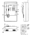
図1は本発明の実施の形態を示す正面図、側面図および底面図である。図において、1はキャビネット本体で、箱状に合成樹脂で成形され、内部に回路基板および電子部品類を内蔵し、背面が建物の壁面等に固定される。2は箱状に合成樹脂で成形されたキャビネット扉で、前面に操作パネル3、ハンドセット本体4、ハンドセットカバー5、ボタン6および表示パネル7が設けられ、内部には回路基板および電子部品類が配備され、前記キャビネット本体1に対峙して、ヒンジ9で開閉可能なように備えられる。8はコインキーで、前記キャビネット本体1とキャビネット扉2とを施錠する。10はカールコードである。
なお、ハンドセット本体4およびハンドセットカバー5をまとめてハンドセットまたは送受話器と呼称する。
【0012】
前記キャビネット本体1には、キャビネット扉2がヒンジ9で片開きするように取り付けられている。このヒンジ9の取付位置は開き部位置と段差を有している。
ここで開き部位置とは、キャビネット本体1の開口側とキャビネット扉2の開口側との接触する面のことをいい、ヒンジ9の取付位置に段差を持たせるために、キャビネット本体1の開口側のヒンジ取付側には段部9aが形成され、また、キャビネット扉2の開口側のヒンジ取付側には、その段部9aに対応する切欠部9bが形成されている。
そして、ヒンジ9の取付位置は開き部位置より前面側に近寄るように構成されている。
【0013】
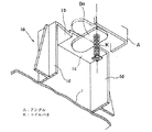
上記のように構成された管理室制御盤においては、図2に示すように複数台を横に並べ、当接させた場合でも、キャビネット扉2を隣接したキャビネット本体1にぶつけることなく、90度以上にわたって開くことができ、内部の点検作業を行いやすい。また管理室制御盤を通話制御装置として使用する場合には、通話制御装置の横には、住宅情報盤や集合玄関機の映像を制御する映像制御装置が隣接して設置されているのが、一般的であるので、このように左右の開閉角度を大きくとれることは好ましい。
【0014】
ヒンジ9の取付位置に段差を有しない場合には、比較例を示す図3で明らかなように、全てのキャビネット扉2を大きく展開できない状態が発生し、このような状態は、隣接どうしを大きな間隔で設置することにより回避できるが、広いスペースが必要となる。
なお、キャビネット本体1の段部9aおよびキャビネット扉2の切欠部9bを大きくすることで、扉の開閉角をより大きくすることが可能となるが、図のように切欠部9bの高さを、扉2の高さの約半分とすることで、強度的にも支障を生じない。
【0015】
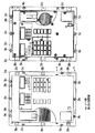
前記キャビネット扉2に設けたコインキー8は、図4〜図6に示すようにキャビネット本体1の底部の内面からコの字状の枠形に立設した筐体ロック部1aにコインキー8の舌状片8aを交叉させて施錠するようになっている。
前記コの字状の筐体ロック部1aの水平片1cにおいて、垂直片1dの片側から上り傾斜となる傾斜部1bが設けられる。傾斜部1bの長さは、水平片1cの長さの約3分の1であり、その高さは舌状片8aの高さと略同じである。
前記舌状片8aは、キャビネット扉2の前面と直交する軸に取付けられ筐体ロック部1aの横側となる位置へ設けられ、前面から回動可能で、その長さ方向に移動自在で、コイルバネKによって、キャビネット扉2の前面方向へ押圧されるように軸に固定されている。
【0016】
なお舌状片8aは、このコイルバネKの影響により、筐体ロック部1a内に位置するときは、コの字状の枠形の水平片1cの内側に押圧されている。
筐体ロック部1aの舌状片8aと当接する平坦な部分は、舌状片8aと同一平面上に設定されている。
なお舌状片8aの横には、扉2裏面側からL字型のアングルAが突出するように設けられ、舌状片8aは90°だけしか回動できないように制限されている。
【0017】
上記のように構成されたコインキー8においては、この実施の形態では、前記舌状片8aは時計回りの矢視方向に回転させる。舌状片8aは矢視方向に回転させると、筐体ロック部1aの内部へ回り込む際に、筐体ロック部1aの傾斜部1bに沿って滑り込むので押圧動作を必要とせずに回転できる。舌状片8aをコの字状の枠形と平行な位置関係にある所(解錠状態)から、90°回転させると傾斜部1bが無くなり、舌状片8aとコの字状枠が直交した状態となり、平坦部(水平片1c)に押圧されて施錠完了となる。この状態から解錠させる場合は、反時計回りに90°回転させればよい。
【0018】
しかし、この場合には、単に回すだけでは舌状片8aが傾斜部1bを乗り越えられないので、コイルバネに抗うように、コインキーの操作部を傾斜部高さ以上に押し込みながら舌状片8aを回転させる。これにより舌状片8aは平坦部から離れ傾斜部1bを乗り越えて筐体ロック部1aから外れ、解錠される。従って、単に回転させるだけで施錠を行えるが、解錠操作は押圧しながら回転させないと解錠できない。
【0019】
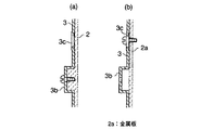
前記操作パネル3は、キャビネット扉2と分離可能に設けられ、枠状に開口を形成したキャビネット扉2の前面へ扉2の裏側から固定する。なお、図7に示すように操作パネル3の周囲は、表面とは段差を有するように設けたツバ部3aを扉の開口へ嵌め込む構成としているが、前記段差は必要に応じて形成するものである。図7および図8に示すように操作パネル3の周囲に所望間隔で形成した固定部3bは、所望間隔で形成したコの字状に段部を有するように成形し、小穴を穿ったものである。また、固定部3cはツバ部3aに長円を穿った構成としている。
【0020】
上記のように構成した操作パネル3を樹脂製のキャビネット扉2に固定する場合は、図8(a)に示すようにキャビネット扉2の枠状に形成した開口の周囲形状を、操作パネル3に設けた固定部3bの段部に嵌まる凸部を設けてタッピングネジ等を使用してビス止めする。
【0021】
操作パネル3を分離独立させて、集合住宅の管理人室あるいは高層ビル、その他の大規模建築物等の管理室の壁に設けた金属板2aまたは金属製の扉に設置するタイプにおいては、固定部3cにリーマネジ付きビスやMネジ等を挿入して、該金属板2aに固定する。従って、扉側の材質が金属であっても、樹脂であっても、簡単に操作パネルを取り付けることができ、壁面直付けタイプおよび埋込設置タイプ等、その他凡ゆる設置型式に対応可能である。
なお、図8bにおいて、ビスは金属板2a側から挿入してもよく、この場合には、操作パネル3c側にナットを設けて、ビスを固定するようにする。
【0022】
【発明の効果】
以上のように本発明によれば、コインキーの操作部を筐体ロック部の傾斜部の高さ以上に押し込みながら舌状片を回転させ、舌状片を傾斜部に乗り越えさせて解錠するようにしたので、管理者以外の者が勝手に扉を開けるのを防止でき、いたずら防止や防犯効果が高まる。
【図面の簡単な説明】
【図1】本発明の実施の形態を示す正面図、側面図および底面図である。
【図2】本発明の実施の形態のキャビネット扉の閉状態および開状態を示す説明図である。
【図3】本発明の比較例のキャビネット扉の閉状態および開状態を示す説明図である。
【図4】本発明の実施の形態を示すキャビネット本体の正面図である。
【図5】図4のK部を示す拡大説明図である。
【図6】図4のK部を示す拡大斜視図である。
【図7】本発明の実施の形態を示す操作パネルの正面図および内面図である。
【図8】図7のY−Y矢視を示す拡大断面図である。
【符号の説明】
1 キャビネット本体
1a 筐体ロック部
1b 傾斜部
2 キャビネット扉
2a 金属板
3 操作パネル
3a ツバ部
3b,3c 固定部
4 ハンドセット本体
5 ハンドセットカバー
6 ボタン
7 表示パネル
8 コインキー
8a 舌状片
9 ヒンジ
10 カールコード[0001]
BACKGROUND OF THE INVENTION
The present invention relates to a control room control panel installed in a management room such as a manager's room or a high-rise building of another housing complex, and other large-scale buildings, for example. The present invention relates to a call control device to which a collective entrance machine or the like is connected and which controls calls of these devices.
[0002]
[Prior art]
For example, a control room control panel installed in a management room of a housing complex or a high-rise building or other large-scale building has a cover (door) so that the inside can be inspected. Is locked with a coin key.
Further, in the conventional control room control panel disclosed in Japanese Patent Laid-Open No. 4-355897, a double frame structure in which the outer frame is connected to the outer periphery of the main body by the connecting rib, and the connecting rib is provided. It is described that a wall surface direct attachment type can be changed to an embedded installation type by cutting and removing the outer frame.
[0003]
[Problems to be solved by the invention]
Locking and unlocking with the coin key used in the conventional control room control panel as described above has a structure in which the tongue piece is turned into the groove and removed from the groove, so anyone can easily open and close the door. There is a problem in terms of safety.
Further, in the case of the double frame structure, there is a problem of disposal processing of the removed outer frame in the case of embedded installation, and there are also problems in terms of complication of molds and resource saving.
[0004]
The present invention has been made to solve such problems, and enhances the crime prevention of the unlocking operation by the coin key, and can be applied to any installation state by configuring a part to be separable and independent. Furthermore, it is an object of the present invention to provide a control room control panel capable of opening and closing a box-shaped lid without any trouble even when a plurality of units are installed adjacent to each other.
[0005]
[Means for Solving the Problems]
A management room control panel according to the present invention includes a coin key having a tongue-like piece movably attached to a shaft while being pressed by a spring, and a management room in which the main body and the door are locked and unlocked by the coin key. A control panel provided with a frame-shaped housing lock portion standing from the inner surface of the main body and having a horizontal piece. The horizontal piece of the housing lock portion is provided at one end of the flat portion and the flat portion from one side. The coin key is locked while the tongue-shaped piece is pressed against the inside of the flat portion by a spring, and the operation portion of the coin key is connected to the inclined portion of the inclined portion. The tongue-like piece is rotated while being pushed above the height, and the tongue-like piece gets over the inclined portion to be unlocked.
[0006]
Further, the horizontal piece of the housing lock portion is erected by the vertical piece, and the inclined portion is formed to rise upward from one side of the vertical piece, and the height of the inclined portion is the same as the height of the tongue-like piece. It is almost the same.
[0011]
DETAILED DESCRIPTION OF THE INVENTION
FIG. 1 is a front view, a side view, and a bottom view showing an embodiment of the present invention. In the figure,
The
[0012]
A
Here, the opening portion position refers to a surface that contacts the opening side of the
And the attachment position of the hinge 9 is comprised so that it may approach the front side from the opening part position.
[0013]
In the control room control panel configured as described above, even when a plurality of units are arranged side by side and brought into contact with each other as shown in FIG. 2, the
[0014]
When there is no step at the mounting position of the hinge 9, as shown in FIG. 3 showing the comparative example, a state where all the
In addition, by increasing the
[0015]
As shown in FIGS. 4 to 6, the
In the horizontal piece 1c of the U-shaped
The tongue-
[0016]
When the tongue-
The flat part which contacts the tongue-
Note that an L-shaped angle A is provided on the side of the tongue-
[0017]
In the
[0018]
However, in this case, since the tongue-
[0019]
The
[0020]
When the
[0021]
In the type where the
In FIG. 8b, the screw may be inserted from the
[0022]
【The invention's effect】
As described above, according to the present invention, the tongue-shaped piece is rotated while pushing the operation part of the coin key more than the height of the inclined part of the housing lock part, and the tongue-like piece gets over the inclined part to unlock. As a result, it is possible to prevent a person other than the administrator from opening the door without permission, thereby increasing the prevention of mischief and crime prevention.
[Brief description of the drawings]
FIG. 1 is a front view, a side view, and a bottom view showing an embodiment of the present invention.
FIG. 2 is an explanatory diagram showing a closed state and an open state of the cabinet door according to the embodiment of the present invention.
FIG. 3 is an explanatory diagram showing a closed state and an open state of a cabinet door according to a comparative example of the present invention.
FIG. 4 is a front view of a cabinet body showing an embodiment of the present invention.
FIG. 5 is an enlarged explanatory view showing a portion K in FIG. 4;
6 is an enlarged perspective view showing a portion K in FIG. 4;
FIGS. 7A and 7B are a front view and an inner view of the operation panel showing the embodiment of the present invention. FIGS.
8 is an enlarged cross-sectional view taken along the line YY in FIG.
[Explanation of symbols]
DESCRIPTION OF
Claims (2)
前記本体の内面から立設され、水平片を有する枠形の筐体ロック部を設け、
該筐体ロック部の水平片を、平坦部と、該平坦部の一端に設けられ片側から前記本体の内面側の中央に向かって上り傾斜となる傾斜部とから構成し、
前記コインキーは、前記舌状片が前記平坦部の内側にバネで押圧されながら施錠されており、
前記コインキーの操作部を傾斜部の高さ以上に押し込みながら前記舌状片を回転させ、前記舌状片を傾斜部に乗り越えさせて解錠することを特徴とする管理室制御盤。A control room control panel comprising a coin key having a tongue-like piece movably attached to a shaft while being pressed by a spring, wherein the main body and the door are locked and unlocked by the coin key ,
Standing from the inner surface of the main body, provided with a frame-shaped housing lock portion having a horizontal piece ,
The horizontal piece of the housing lock part is composed of a flat part and an inclined part that is provided at one end of the flat part and is inclined upward from one side toward the center on the inner surface side of the main body ,
The coin key is locked while the tongue-like piece is pressed by a spring inside the flat portion,
A control room control panel characterized in that the tongue-shaped piece is rotated while pushing the operation part of the coin key to the height of the inclined part or more, and the tongue-like piece gets over the inclined part to be unlocked .
Priority Applications (1)
| Application Number | Priority Date | Filing Date | Title |
|---|---|---|---|
| JP06165699A JP3783193B2 (en) | 1999-03-09 | 1999-03-09 | Control room control panel |
Applications Claiming Priority (1)
| Application Number | Priority Date | Filing Date | Title |
|---|---|---|---|
| JP06165699A JP3783193B2 (en) | 1999-03-09 | 1999-03-09 | Control room control panel |
Related Child Applications (1)
| Application Number | Title | Priority Date | Filing Date |
|---|---|---|---|
| JP2006021335A Division JP3885089B2 (en) | 2006-01-30 | 2006-01-30 | Control room control panel |
Publications (3)
| Publication Number | Publication Date |
|---|---|
| JP2000259972A JP2000259972A (en) | 2000-09-22 |
| JP2000259972A5 JP2000259972A5 (en) | 2004-10-07 |
| JP3783193B2 true JP3783193B2 (en) | 2006-06-07 |
Family
ID=13177497
Family Applications (1)
| Application Number | Title | Priority Date | Filing Date |
|---|---|---|---|
| JP06165699A Expired - Fee Related JP3783193B2 (en) | 1999-03-09 | 1999-03-09 | Control room control panel |
Country Status (1)
| Country | Link |
|---|---|
| JP (1) | JP3783193B2 (en) |
Families Citing this family (6)
| Publication number | Priority date | Publication date | Assignee | Title |
|---|---|---|---|---|
| JP4634631B2 (en) * | 2001-03-22 | 2011-02-16 | アイホン株式会社 | Nurse call device |
| JP4936452B2 (en) * | 2007-02-23 | 2012-05-23 | パナソニックエコソリューションズ電路株式会社 | Distribution board |
| JP2008240439A (en) * | 2007-03-28 | 2008-10-09 | Saxa Inc | Locking structure of case body |
| KR101662034B1 (en) * | 2016-04-29 | 2016-10-04 | (주)삼경엠에스 | Facility Managing System for Reading Meter |
| JP7384589B2 (en) | 2019-07-31 | 2023-11-21 | ニッタン株式会社 | Receiver for disaster prevention monitoring system |
| JP7383415B2 (en) | 2019-07-31 | 2023-11-20 | ニッタン株式会社 | Receiver for disaster prevention monitoring system |
-
1999
- 1999-03-09 JP JP06165699A patent/JP3783193B2/en not_active Expired - Fee Related
Also Published As
| Publication number | Publication date |
|---|---|
| JP2000259972A (en) | 2000-09-22 |
Similar Documents
| Publication | Publication Date | Title |
|---|---|---|
| JP3783193B2 (en) | Control room control panel | |
| US6970084B2 (en) | Alarm generating door lock | |
| JP3885089B2 (en) | Control room control panel | |
| JP3124028U (en) | Slot machine power supply box tamper-proof cover | |
| JPS6317267Y2 (en) | ||
| JP4005954B2 (en) | Switch box | |
| JP3194927U (en) | Waterproof traffic signal controller | |
| JP2000259972A5 (en) | ||
| JP3338786B2 (en) | Wall mounting structure of equipment housing | |
| KR101051922B1 (en) | Digital door lock system capable of mounting in setting hole for door locking apparatus | |
| JPH10162678A (en) | Switch box structure | |
| KR100263981B1 (en) | A door lock system | |
| KR200407876Y1 (en) | Locking device for electric type door-lock | |
| JP2006037698A (en) | Thumbturn dishonest unlocking preventive member | |
| JP3177828U (en) | Handle cover with locking function | |
| JP4314889B2 (en) | Electric lock controller unit mounting structure | |
| JP4441922B2 (en) | Security cover for Crescent lock | |
| JP2023056566A (en) | Key storage device | |
| KR200346800Y1 (en) | Safety Cap for Manual Lever of Door Lock | |
| KR20080004748U (en) | Door lock with convenient double locking removal | |
| KR100734030B1 (en) | Locking device for electric type door-lock | |
| JP2988230B2 (en) | Locking device | |
| JP2023063787A (en) | Key storage device | |
| JP2988228B2 (en) | Locking device | |
| JP3067196U (en) | Door device with a function to prevent unauthorized unlocking of the front of the gaming machine stand |
Legal Events
| Date | Code | Title | Description |
|---|---|---|---|
| A977 | Report on retrieval |
Free format text: JAPANESE INTERMEDIATE CODE: A971007 Effective date: 20051115 |
|
| A131 | Notification of reasons for refusal |
Free format text: JAPANESE INTERMEDIATE CODE: A131 Effective date: 20051129 |
|
| A521 | Written amendment |
Free format text: JAPANESE INTERMEDIATE CODE: A523 Effective date: 20060127 |
|
| TRDD | Decision of grant or rejection written | ||
| A01 | Written decision to grant a patent or to grant a registration (utility model) |
Free format text: JAPANESE INTERMEDIATE CODE: A01 Effective date: 20060221 |
|
| A61 | First payment of annual fees (during grant procedure) |
Free format text: JAPANESE INTERMEDIATE CODE: A61 Effective date: 20060303 |
|
| R150 | Certificate of patent or registration of utility model |
Free format text: JAPANESE INTERMEDIATE CODE: R150 |
|
| FPAY | Renewal fee payment (event date is renewal date of database) |
Free format text: PAYMENT UNTIL: 20090324 Year of fee payment: 3 |
|
| FPAY | Renewal fee payment (event date is renewal date of database) |
Free format text: PAYMENT UNTIL: 20100324 Year of fee payment: 4 |
|
| FPAY | Renewal fee payment (event date is renewal date of database) |
Free format text: PAYMENT UNTIL: 20110324 Year of fee payment: 5 |
|
| FPAY | Renewal fee payment (event date is renewal date of database) |
Free format text: PAYMENT UNTIL: 20110324 Year of fee payment: 5 |
|
| LAPS | Cancellation because of no payment of annual fees |