JP3781908B2 - Piston pump - Google Patents
Piston pump Download PDFInfo
- Publication number
- JP3781908B2 JP3781908B2 JP32939298A JP32939298A JP3781908B2 JP 3781908 B2 JP3781908 B2 JP 3781908B2 JP 32939298 A JP32939298 A JP 32939298A JP 32939298 A JP32939298 A JP 32939298A JP 3781908 B2 JP3781908 B2 JP 3781908B2
- Authority
- JP
- Japan
- Prior art keywords
- pump
- piston
- fixed
- variable
- cylinder
- Prior art date
- Legal status (The legal status is an assumption and is not a legal conclusion. Google has not performed a legal analysis and makes no representation as to the accuracy of the status listed.)
- Expired - Fee Related
Links
Images


Landscapes
- Reciprocating Pumps (AREA)
- Details Of Reciprocating Pumps (AREA)
Description
【0001】
【発明の属する技術分野】
本発明は、可変容量ピストンポンプに固定容量ポンプを付加した多連式ピストンポンプの改良に関する。
【0002】
【従来の技術】
従来から、例えば建設機械用の油圧ポンプとして、可変容量の斜板式ピストンポンプを多連式としたものが知られている。このような多連式の斜板式ピストンポンプにおいては、同心円上に多数配設された複数のピストンに対して、キドニーポートが異なる径の同心円状に配設された複数系統(例えば2系統)設けられ、各系統ごとに異なるポンプとして吸込および吐出を行うようになっている。
【0003】
図6には、このような2連式の斜板式アキシャルピストンポンプ100に、固定容量のギヤポンプ110を付加して、3連式ポンプとしたものを示す。
【0004】
図示されるように、斜板式アキシャルピストンポンプ100のポンプケース101には駆動軸102が軸支される。ポンプケース101内に収容されたシリンダブロック103は、駆動軸102とスプライン結合し、駆動軸102とともに回転自在となっている。駆動軸102は、ポンプケース101からの突出端において、図示されない駆動モータにより回転駆動される。
【0005】
シリンダブロック103の上面には、駆動軸102を中心とするピストンピッチ円上に、複数のシリンダ104が開口し、各シリンダ104にはピストン105が摺動自在に収容される。一方、シリンダブロック103の底面には弁板106が当接し、この弁板106には吸込側および吐出側のキドニーポートが形成される。この場合、吸込側および吐出側のキドニーポートは、それぞれ内側と外側に2重に形成され、各ピストンシリンダは外側のキドニーポートか内側のキドニーポートに選択的に連通するようになっている。
【0006】
傾転角が変更可能な斜板107は、シリンダブロック103の上面に相対して配置され、ピストン105の突出端がピストンシュー108を介して斜板に当接する。これにより、シリンダブロック103が回転すると、シリンダ104の内部がピストン105により拡縮され、吸込側キドニーポートからの作動油の吸い込みと、吐出側キドニーポートへの作動油の吐き出しがなされる。
【0007】
ポンプケース101にはギヤポンプ110が固定される。このギヤポンプ110の駆動軸111は、シリンダブロック103を貫通した駆動軸102と連結されている。これにより、ギヤポンプ110はピストンポンプ100と同期して駆動されるようになっている。
【0008】
ギヤポンプ110からの吐出圧は、ギヤポンプ110とピストンポンプ100の間に設置された導油用のブッシュ112を通ってピストンポンプ100に導かれる。ピストンポンプ100の斜板107の傾転角は、ピストンポンプ100からの吐出圧およびこのギヤポンプ110からの吐出圧に基づいてフィードバック制御され、多連式ポンプ全体(すなわち可変ポンプであるピストンポンプ100と固定ポンプであるギヤポンプ110の全体)の全出力について、定馬力制御がなされるようになっている。
【0009】
【発明が解決しようとする課題】
しかしながら、このような図6の多連式ポンプでは、ピストンポンプ100の駆動軸102の延長上にギヤポンプ110が配置されるので、ポンプの全長が長くなってしまう。
【0010】
また、ギヤポンプ110の吐出圧をピストンポンプ100側に導くブッシュ112には高圧シールを行う必要があるので、Oリング113等が必要となり部品点数が多くなる。
【0011】
また、ギヤポンプ110をピストンポンプ100に組み付ける際には、インロー部の組み付けと同時に、ブッシュ112や駆動軸111の組み付けが必要となるので、組み立てが複雑で手間がかかる上、組み立て精度も要求される。
【0012】
本発明は、このような問題点に着目してなされたもので、可変容量ピストンポンプに固定容量ポンプを組み合わせた多連式ポンプにおいて、ポンプ全体を小型化できるとともに、部品点数を削減でき、また組み立ても容易であるものを提供することを目的とする。
【0013】
【課題を解決するための手段】
第1の発明は、ポンプケース内に収容されたシリンダブロックを備えたピストンポンプにおいて、前記シリンダブロックに形成された複数の可変ポンプ側シリンダと、前記シリンダブロックの前記可変ポンプ側シリンダとは異なるピストンピッチ円上に形成された複数の固定ポンプ側シリンダと、前記可変ポンプ側シリンダに収容された可変ポンプ側ピストンの突出端側が当接する傾転角の変更可能な可変斜板と、この可変斜板の傾転角を制御する傾転角制御手段と、 前記固定ポンプ側シリンダに収容された固定ポンプ側ピストンの突出端側が当接する傾転角固定の固定斜板とを備え、前記シリンダブロックの段差部に前記固定ポンプ側シリンダを開口するとともに、前記固定斜板を前記シリンダブロックの回りに配設した。
【0015】
第2の発明は、前記固定ポンプ側ピストンをシュー無しピストンとした。
【0016】
第3の発明は、前記可変ポンプ側シリンダと前記固定ポンプ側シリンダを共通の吸込ポートに連通可能とした。
【0017】
【発明の作用および効果】
第1の発明では、ピストンポンプを作動させると可変ポンプ側シリンダおよび固定ポンプ側シリンダから作動油の吐出がなされ、ポンプは多連式ポンプとして作用するが、傾転角制御手段はこの可変ポンプ側シリンダからの吐出圧と固定ポンプ側シリンダからの吐出圧に基づいて可変斜板の傾転角を制御し、例えばピストンポンプの定馬力制御を行う。この場合、固定ポンプ側シリンダから傾転角制御手段に導かれる吐出圧は、ポンプケース内の油路を通じて導くことができ、固定ポンプをポンプケース外部に取り付けた場合のようにシール部材等が必要なくなるので、ポンプの部品点数が削減できる。また、ポンプの可変ポンプとして作用する構成と固定ポンプとして作用する構成はコンパクトにまとめられてポンプケース内に一体に収容されるので、ポンプの駆動軸延長上に固定ポンプを取り付けた場合のようにポンプの全長が長くなってしまうことはなく、ポンプの小型化を図り得るとともに、固定ポンプをポンプケースの外側から組み付ける必要がないので、ポンプ製造が容易となる。また、固定ポンプ側シリンダはシリンダブロックの段差部に形成し、固定斜板はシリンダブロックの回りに配設するようにしたので、シリンダブロックおよび固定斜板は合理的にコンパクトな構成とでき、ポンプの小型化を図り得る。
【0019】
第2の発明では、固定ポンプ側ピストンをシュー無しとしたので、ピストンシューがシリンダブロックと干渉する恐れがなく、固定ポンプ側ピストンをシリンダブロック外周に寄せて配置することが可能となり、固定ポンプ側ピストンのピストンピッチ円の径を小さくして、シリンダブロックを小型化できる。よって、ポンプの小型化をさらに図り得る。
【0020】
第3の発明では、可変ポンプ側シリンダと固定ポンプ側シリンダとで吸込ポートが共通化されるので、ポンプの吸込配管を簡略化できる。
【0021】
【発明の実施の形態】
以下、添付図面に基づいて、本発明の実施の形態について説明する。
【0022】
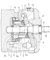
図1には、本発明の実施の形態の多連式ポンプを示す。
【0023】
図示されるように、ポンプケース1には、駆動軸2が軸受を介して回転自在に軸支される。この駆動軸2は、突出端2Aにおいて図示されない駆動モータに接続され、回転駆動される。また、ポンプケース1内部には、シリンダブロック3が収容され、このシリンダブロック3は、シリンダブロック3を貫通して形成された駆動軸穴4において駆動軸2とスプライン結合され、駆動軸2と一体に回転駆動されるようになっている。
【0024】
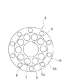
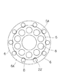
図2、図3にも示すように、シリンダブロック3は、可変ポンプ部5と固定ポンプ部6からなる。可変ポンプ部5は、駆動軸穴4の回りの円環状部分であり、その上面5Aには、所定のピストンピッチ円上に複数の可変ポンプ側シリンダ7が開口する。一方、固定ポンプ部6は、シリンダブロック3の底面3A側をフランジ状にした部分で、この固定ポンプ部6の上面6Aはシリンダブロック3における段差部となる。そして、この上面6Aの所定のピストンピッチ円上に、複数の固定ポンプ側シリンダ8が開口する。可変ポンプ側シリンダ7には可変ポンプ側ピストン10が、固定ポンプ側シリンダ8には固定用ポンプ用ピストン11が、それぞれ摺動自在に挿入される。
【0025】
シリンダブロック3の底面3Aは、ポンプケース1に固定の弁板12に当接する。弁板12には、可変ポンプ側と固定ポンプ側のキドニーポート(吸込ポートと吐出ポート)がそれぞれ形成され、各可変ポンプ側シリンダ7は可変ポンプ側の吸込ポートまたは吐出ポートに、固定ポンプ側シリンダ8は固定ポンプ側の吸込ポートまたは吐出ポートに、それぞれシリンダブロック3の回転に応じて選択的に接続可能となっている。
【0026】
なお、可変ポンプ側キドニーポートとしては、異なる同心円上配置された複数の系統(例えば2系統)の吸込ポートおよび吐出ポートを備えるようにして、各系統が異なる可変ポンプとして作用するようにしてもよい。
【0027】
駆動軸2の回りには、シリンダブロック3に対する傾転角の変更可能な可変斜板13が備えられる。この可変斜板13は、可変ポンプ部上面5Aと正対するように配置され、可変ポンプ側ピストン10の突出端はピストンシュー14を介して可変斜板13に当接する。これにより、シリンダブロック3が回転すると、可変ポンプ側ピストン10が伸縮し、可変ポンプ側シリンダ7内の空間を拡縮することにより、弁板3Aの可変ポンプ側吸込ポートから作動油の吸込がなされ、可変ポンプ側吐出ポートから作動油の吐出がなされる。
【0028】
この場合、可変ポンプ側吐出ポートからの吐出量は、可変斜板13の傾転角に応じて決まって来るが、この可変斜板13の傾転角は、図示されない傾転角制御手段により制御される。この傾転角制御手段には、可変ポンプ側吐出ポートからの吐出圧と固定ポンプ側吐出ポートからの吐出圧が、ポンプケース1内部に形成された図示されない油路を通って導かれるようになっている。
【0029】
シリンダブロック3の可変ポンプ部5の外周には、傾転角固定の固定斜板15が配設され、ポンプケース1に固定される。この固定斜板15は、固定ポンプ部上面6Aと正対し、固定ポンプ側ピストン11の突出端がピストンシュー16を介して当接する。これにより、シリンダブロック3が回転すると、伸縮する固定ポンプ側ピストン11により固定ポンプ側シリンダ8が拡縮し、固定ポンプ側吸込ポートからの作動油の吸込と、固定ポンプ側吐出ポートへの作動油の吐出がなされる。なお、固定斜板15は傾転角一定であるので、固定ポンプ側吐出ポートからの吐出量は一定である。
【0030】
つぎに作用を説明する。
【0031】
多連式ピストンポンプを駆動する場合には、駆動モータによりポンプの駆動軸2を回転駆動させ、シリンダブロック3を回転させる。これにより、可変ポンプ側ピストン10および固定ポンプ側ピストン11が可変ポンプ側シリンダ7および固定ポンプ側シリンダ8内を伸縮して、可変ポンプ側吸込ポートおよび固定ポンプ側吸込ポートからの作動油の吸込と、可変ポンプ側吐出ポートおよび固定ポンプ側吐出ポートからの作動油の吐出がなされる。可変ポンプ側吐出ポートの各系統および固定ポンプよう吐出ポートから吐出された作動油は、それぞれ各種油圧機器に供給される。
【0032】
この場合、ポンプの全出力(吐出圧×吐出量)は、所定の一定馬力(例えば駆動モータの定格駆動力に見合った馬力)に制御される必要がある。このため、可変ポンプ側吐出ポートおよび固定ポンプ側吐出ポートからの吐出圧は、ポンプケース1内部に形成された油路を通じて傾転角制御手段にフィードバックされる。傾転角制御手段は、これらの吐出圧に基づいて、斜板14の傾転角を変更して可変ポンプ側吐出ポートからの吐出量を制御し、ポンプの全出力(可変ポンプおよび固定ポンプ全体の出力)が一定となるようにフィードバック制御を行う。
【0033】
このように本発明の多連式ピストンポンプによれば、固定ポンプ側吐出ポートからの吐出圧は、ポンプケース1内部の油路を通じて傾転角制御手段に送られるので、固定ポンプ側からの導油のためのブッシュ等が不要となり、またシール部材等を備える必要がなく、部品点数の削減が図れる。
【0034】
また、本発明の多連式ピストンポンプでは、一つのシリンダブロック3に可変ポンプ部5と固定ポンプ部6が備えられるので、可変ポンプとして作用する構成と固定ポンプとして作用する構成がコンパクトにまとめられ、ポンプケース1内に一体に収容される。したがって、多連式ピストンポンプの小型化を図ることができる。
【0035】
また、本発明の多連式ピストンポンプでは、ケーシング1の外部から固定ポンプを組み付ける必要がないので、複雑かつ面倒な組み立て作業が必要なく、ポンプの製造も容易に行い得る。
【0036】
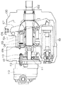
図4、図5には、本発明の他の実施の形態を示す。この実施の形態は、基本的構成においては図1に示した実施の形態と同一であるので、図1のピストンポンプとの相違点を中心に説明する。
【0037】
この実施の形態のピストンポンプでは、図1〜図3の実施の形態の固定ポンプ側ピストン11とピストンシュー16の代わりに、シュー無しの固定ポンプ側ピストン21を採用している。このようにピストンシューを無くすことにより、ピストンシューがシリンダブロック3の可変ポンプ部5外周と干渉する問題がなくなるので、固定ポンプ側シリンダ8を可変ポンプ部5側に寄せて形成できる。具体的には、可変ポンプ部5外周に窪み部22を形成し、固定ポンプ側シリンダ8をこの窪み部22にまで寄せて配置できる。これにより、固定ポンプ側シリンダ8のピストンピッチ円半径を小さくして、シリンダブロック3の小型化を図ることができるので、さらにポンプの小型化を図れる。
【0038】
なお、上記の各実施の形態では、可変ポンプ側吸込ポートと固定ポンプ側吸込ポートを別々に設けるようにしたが、本発明はこのような形態に限られるものではなく、可変ポンプ側吸込ポートと固定ポンプ側吸込ポートを共通化して一つの吸込ポートとしてもよい。さらにこの場合、ピストンポンプに設置されるパイロットポンプ(例えばトロコイドポンプ)の吸込ポートを共通化してもよい。このようにポンプの吸込配管を共通化することにより、ポンプ構成を簡略化することができる。
【0039】
また、上記の各実施の形態では、可変ポンプ側シリンダ7のピストンピッチ円と固定ポンプ側シリンダ8のピストンピッチ円はそれぞれ1つづつとなっているが、本発明はこのような形態に限られず、これらのピストンピッチ円をそれぞれ複数個としてもよい。また、可変ポンプ側シリンダ7だけでなく、固定ポンプ側シリンダ8も複数系統に分け、多数のポンプとして作用させることも当然に可能である。
【図面の簡単な説明】
【図1】本発明の実施の形態を示すピストンポンプの断面図である。
【図2】同じくシリンダブロックの平面図である。
【図3】同じくシリンダブロックの側面図である。
【図4】本発明の他の実施の形態を示すピストンポンプの断面図である。
【図5】同じくシリンダブロックの平面図である。
【図6】従来の多連式ピストンポンプを示す断面図である。
【符号の説明】
1 ポンプケース
2 駆動軸
3 シリンダブロック
5 可変ポンプ部
6 固定ポンプ部
7 可変ポンプ側シリンダ
8 固定ポンプ側シリンダ
10 可変ポンプ側ピストン
11 固定ポンプ側ピストン
12 弁板
13 可変斜板
15 固定斜板
21 固定ポンプ側ピストン
22 窪み部[0001]
BACKGROUND OF THE INVENTION
The present invention relates to an improvement of a multiple piston pump in which a fixed displacement pump is added to a variable displacement piston pump.
[0002]
[Prior art]
2. Description of the Related Art Conventionally, for example, as a hydraulic pump for a construction machine, a variable capacity swash plate type piston pump that is a multiple type is known. In such a multiple swash plate type piston pump, a plurality of systems (for example, two systems) in which kidney ports are arranged concentrically with different diameters are provided for a plurality of pistons arranged concentrically. Therefore, suction and discharge are performed as different pumps for each system.
[0003]
FIG. 6 shows a triple pump obtained by adding a fixed
[0004]
As shown in the figure, a
[0005]
On the upper surface of the
[0006]
The
[0007]
A
[0008]
The discharge pressure from the
[0009]
[Problems to be solved by the invention]
However, in such a multiple pump of FIG. 6, since the
[0010]
Further, since the
[0011]
Further, when the
[0012]
The present invention has been made paying attention to such problems, and in a multiple pump in which a fixed displacement pump is combined with a variable displacement piston pump, the entire pump can be reduced in size and the number of parts can be reduced. An object is to provide an assembly that is easy to assemble.
[0013]
[Means for Solving the Problems]
1st invention is a piston pump provided with the cylinder block accommodated in the pump case. WHEREIN: The several variable pump side cylinder formed in the said cylinder block, and the piston different from the said variable pump side cylinder of the said cylinder block A plurality of fixed pump side cylinders formed on the pitch circle, a variable swash plate whose changeable tilt angle is in contact with the protruding end side of the variable pump side piston housed in the variable pump side cylinder, and the variable swash plate A tilt angle control means for controlling the tilt angle of the cylinder block, and a fixed swash plate with a fixed tilt angle with which the protruding end side of the fixed pump side piston accommodated in the fixed pump side cylinder comes into contact. The fixed pump side cylinder was opened at a portion, and the fixed swash plate was disposed around the cylinder block .
[0015]
In the second invention, the stationary pump side piston is a shoeless piston.
[0016]
In a third aspect of the invention, the variable pump side cylinder and the fixed pump side cylinder can communicate with a common suction port.
[0017]
Operation and effect of the invention
In the first aspect of the invention, when the piston pump is operated, the hydraulic oil is discharged from the variable pump side cylinder and the fixed pump side cylinder, and the pump acts as a multiple pump. The tilt angle of the variable swash plate is controlled based on the discharge pressure from the cylinder and the discharge pressure from the fixed pump side cylinder, for example, constant horsepower control of a piston pump is performed. In this case, the discharge pressure guided from the fixed pump side cylinder to the tilt angle control means can be guided through the oil passage in the pump case, and a seal member is required as in the case where the fixed pump is mounted outside the pump case. This eliminates the number of pump parts. In addition, the configuration that acts as a variable pump of the pump and the configuration that acts as a fixed pump are compactly integrated and housed in the pump case, so that the fixed pump is mounted on the pump drive shaft extension. The total length of the pump does not increase, the pump can be miniaturized, and the fixed pump does not need to be assembled from the outside of the pump case, so that the pump can be manufactured easily. In addition, the fixed pump side cylinder is formed in the step part of the cylinder block, and the fixed swash plate is arranged around the cylinder block. Therefore, the cylinder block and the fixed swash plate can be reasonably compact, and the pump Can be miniaturized.
[0019]
In the second invention, since the fixed pump side piston has no shoe, there is no possibility that the piston shoe interferes with the cylinder block, and the fixed pump side piston can be arranged close to the outer periphery of the cylinder block. The cylinder block can be downsized by reducing the diameter of the piston pitch circle of the piston. Therefore, the pump can be further reduced in size.
[0020]
In the third invention, since the suction port is shared by the variable pump side cylinder and the fixed pump side cylinder, the suction pipe of the pump can be simplified.
[0021]
DETAILED DESCRIPTION OF THE INVENTION
Hereinafter, embodiments of the present invention will be described with reference to the accompanying drawings.
[0022]
FIG. 1 shows a multiple pump according to an embodiment of the present invention.
[0023]
As shown in the figure, a
[0024]
As shown in FIGS. 2 and 3, the
[0025]
A
[0026]
In addition, as the variable pump side kidney port, a plurality of systems (for example, 2 systems) of suction ports and discharge ports arranged on different concentric circles may be provided so that each system may act as a different variable pump. .
[0027]
A
[0028]
In this case, the discharge amount from the variable pump side discharge port is determined according to the tilt angle of the
[0029]
A fixed
[0030]
Next, the operation will be described.
[0031]
When driving a multiple piston pump, the
[0032]
In this case, the total output of the pump (discharge pressure × discharge amount) needs to be controlled to a predetermined constant horsepower (for example, horsepower commensurate with the rated drive force of the drive motor). For this reason, the discharge pressure from the variable pump side discharge port and the fixed pump side discharge port is fed back to the tilt angle control means through the oil passage formed inside the pump case 1. The tilt angle control means changes the tilt angle of the
[0033]
As described above, according to the multiple piston pump of the present invention, the discharge pressure from the fixed pump side discharge port is sent to the tilt angle control means through the oil passage inside the pump case 1, so that the pressure from the fixed pump side is guided. There is no need for a bush for oil, and there is no need to provide a seal member or the like, and the number of parts can be reduced.
[0034]
Further, in the multiple piston pump of the present invention, the
[0035]
Further, in the multiple piston pump of the present invention, it is not necessary to assemble a fixed pump from the outside of the casing 1, so that complicated and troublesome assembly work is not necessary, and the pump can be easily manufactured.
[0036]
4 and 5 show another embodiment of the present invention. Since this embodiment is the same as the embodiment shown in FIG. 1 in the basic configuration, the difference from the piston pump in FIG. 1 will be mainly described.
[0037]
In the piston pump of this embodiment, a fixed
[0038]
In each of the above embodiments, the variable pump side suction port and the fixed pump side suction port are provided separately, but the present invention is not limited to such a form, and the variable pump side suction port and The suction port on the fixed pump side may be shared to form one suction port. Further, in this case, a suction port of a pilot pump (for example, a trochoid pump) installed in the piston pump may be shared. In this way, the pump configuration can be simplified by sharing the pump suction pipe.
[0039]
Further, in each of the above embodiments, the piston pitch circle of the variable
[Brief description of the drawings]
FIG. 1 is a cross-sectional view of a piston pump showing an embodiment of the present invention.
FIG. 2 is a plan view of the cylinder block.
FIG. 3 is a side view of the cylinder block.
FIG. 4 is a sectional view of a piston pump showing another embodiment of the present invention.
FIG. 5 is a plan view of the cylinder block.
FIG. 6 is a cross-sectional view showing a conventional multiple piston pump.
[Explanation of symbols]
DESCRIPTION OF SYMBOLS 1
Claims (3)
前記シリンダブロックに形成された複数の可変ポンプ側シリンダと、
前記シリンダブロックの前記可変ポンプ側シリンダとは異なるピストンピッチ円上に形成された複数の固定ポンプ側シリンダと、
前記可変ポンプ側シリンダに収容された可変ポンプ側ピストンの突出端側が当接する傾転角の変更可能な可変斜板と、
この可変斜板の傾転角を制御する傾転角制御手段と、
前記固定ポンプ側シリンダに収容された固定ポンプ側ピストンの突出端側が当接する傾転角固定の固定斜板と、を備え、
前記シリンダブロックの段差部に前記固定ポンプ側シリンダを開口するとともに、前記固定斜板を前記シリンダブロックの回りに配設したことを特徴とするピストンポンプ。In a piston pump having a cylinder block housed in a pump case,
A plurality of variable pump cylinders formed in the cylinder block;
A plurality of fixed pump side cylinders formed on a piston pitch circle different from the variable pump side cylinder of the cylinder block;
A variable swash plate capable of changing a tilt angle with which a protruding end side of a variable pump side piston accommodated in the variable pump side cylinder comes into contact;
A tilt angle control means for controlling the tilt angle of the variable swash plate;
A fixed swash plate with a fixed tilt angle with which the protruding end side of the fixed pump side piston housed in the fixed pump side cylinder abuts ,
A piston pump, wherein the fixed pump side cylinder is opened at a step portion of the cylinder block, and the fixed swash plate is disposed around the cylinder block .
Priority Applications (1)
| Application Number | Priority Date | Filing Date | Title |
|---|---|---|---|
| JP32939298A JP3781908B2 (en) | 1998-11-19 | 1998-11-19 | Piston pump |
Applications Claiming Priority (1)
| Application Number | Priority Date | Filing Date | Title |
|---|---|---|---|
| JP32939298A JP3781908B2 (en) | 1998-11-19 | 1998-11-19 | Piston pump |
Publications (2)
| Publication Number | Publication Date |
|---|---|
| JP2000154775A JP2000154775A (en) | 2000-06-06 |
| JP3781908B2 true JP3781908B2 (en) | 2006-06-07 |
Family
ID=18220931
Family Applications (1)
| Application Number | Title | Priority Date | Filing Date |
|---|---|---|---|
| JP32939298A Expired - Fee Related JP3781908B2 (en) | 1998-11-19 | 1998-11-19 | Piston pump |
Country Status (1)
| Country | Link |
|---|---|
| JP (1) | JP3781908B2 (en) |
Cited By (3)
| Publication number | Priority date | Publication date | Assignee | Title |
|---|---|---|---|---|
| CN102588266A (en) * | 2012-03-02 | 2012-07-18 | 张意 | Novel high-pressure plunger piston fixed displacement pump |
| CN102588265A (en) * | 2012-03-02 | 2012-07-18 | 张意 | Novel high-pressure piston variable pump |
| DE102021118386A1 (en) | 2020-07-15 | 2022-01-20 | Eaton Intelligent Power Limited | INLINE PISTON PUMP |
Families Citing this family (6)
| Publication number | Priority date | Publication date | Assignee | Title |
|---|---|---|---|---|
| JP2002256804A (en) * | 2001-03-06 | 2002-09-11 | Honda Motor Co Ltd | Rotary fluid machine |
| JP2002256805A (en) * | 2001-03-06 | 2002-09-11 | Honda Motor Co Ltd | Rotary fluid machine |
| JP4262213B2 (en) | 2005-03-14 | 2009-05-13 | ヤンマー株式会社 | Backhoe loader hydraulic circuit |
| DE102013218965A1 (en) * | 2013-09-20 | 2015-03-26 | Ksb Aktiengesellschaft | Membrane separation processes |
| JP7274916B2 (en) * | 2019-04-03 | 2023-05-17 | ナブテスコ株式会社 | Pump units and construction machinery |
| CN113503235B (en) * | 2021-06-07 | 2023-07-25 | 中航力源液压股份有限公司 | Variable adjusting mechanism for hydraulic pump |
-
1998
- 1998-11-19 JP JP32939298A patent/JP3781908B2/en not_active Expired - Fee Related
Cited By (3)
| Publication number | Priority date | Publication date | Assignee | Title |
|---|---|---|---|---|
| CN102588266A (en) * | 2012-03-02 | 2012-07-18 | 张意 | Novel high-pressure plunger piston fixed displacement pump |
| CN102588265A (en) * | 2012-03-02 | 2012-07-18 | 张意 | Novel high-pressure piston variable pump |
| DE102021118386A1 (en) | 2020-07-15 | 2022-01-20 | Eaton Intelligent Power Limited | INLINE PISTON PUMP |
Also Published As
| Publication number | Publication date |
|---|---|
| JP2000154775A (en) | 2000-06-06 |
Similar Documents
| Publication | Publication Date | Title |
|---|---|---|
| US4578948A (en) | Reversible flow vane pump with improved porting | |
| US4807519A (en) | Piston machine with changeable displacement | |
| US4967556A (en) | Hydrostatically operated continuously variable transmission | |
| JP3781908B2 (en) | Piston pump | |
| EP1249640B1 (en) | Swash plate type hydraulic transmission | |
| CN100545453C (en) | Rotary machine | |
| JP4649007B2 (en) | Variable displacement piston unit with electrically actuated variable displacement control and timing control | |
| US4405288A (en) | Variable displacement hydraulic pump and controls therefor | |
| JP4124715B2 (en) | Swash plate type hydraulic pump / motor | |
| US4522565A (en) | Steering gear control valve for variable displacement pump | |
| JPH10184532A (en) | Variable displacement piston pump | |
| JP7430495B2 (en) | Fluid machinery and construction machinery | |
| JP4226879B2 (en) | Variable capacity swash plate type hydraulic rotating machine | |
| JP2006214356A (en) | Multi-stage piston type fixed displacement axial piston pump / motor | |
| EP3561298A1 (en) | Piston hydraulic device | |
| WO2021020217A1 (en) | Hydraulic pump and hydraulic device | |
| JP2000356183A (en) | Axial piston pump | |
| US6358025B1 (en) | Hydraulic rotating axial piston engine | |
| JP2610303B2 (en) | Variable displacement vane pump | |
| US7314354B2 (en) | Rotor machine | |
| JP3962511B2 (en) | Multiple pump structure | |
| JPS63203959A (en) | Hydraulic oil distribution device for swash plate type hydraulic system | |
| JP2600283Y2 (en) | Vibration generator | |
| JPH11351131A (en) | Swash plate piston pump | |
| JP2024120539A (en) | Hydraulic Rotating Machinery |
Legal Events
| Date | Code | Title | Description |
|---|---|---|---|
| A977 | Report on retrieval |
Free format text: JAPANESE INTERMEDIATE CODE: A971007 Effective date: 20051118 |
|
| A131 | Notification of reasons for refusal |
Free format text: JAPANESE INTERMEDIATE CODE: A131 Effective date: 20051129 |
|
| A521 | Written amendment |
Free format text: JAPANESE INTERMEDIATE CODE: A523 Effective date: 20060127 |
|
| TRDD | Decision of grant or rejection written | ||
| A01 | Written decision to grant a patent or to grant a registration (utility model) |
Free format text: JAPANESE INTERMEDIATE CODE: A01 Effective date: 20060228 |
|
| A61 | First payment of annual fees (during grant procedure) |
Free format text: JAPANESE INTERMEDIATE CODE: A61 Effective date: 20060308 |
|
| FPAY | Renewal fee payment (event date is renewal date of database) |
Free format text: PAYMENT UNTIL: 20090317 Year of fee payment: 3 |
|
| FPAY | Renewal fee payment (event date is renewal date of database) |
Free format text: PAYMENT UNTIL: 20100317 Year of fee payment: 4 |
|
| FPAY | Renewal fee payment (event date is renewal date of database) |
Free format text: PAYMENT UNTIL: 20110317 Year of fee payment: 5 |
|
| FPAY | Renewal fee payment (event date is renewal date of database) |
Free format text: PAYMENT UNTIL: 20120317 Year of fee payment: 6 |
|
| FPAY | Renewal fee payment (event date is renewal date of database) |
Free format text: PAYMENT UNTIL: 20130317 Year of fee payment: 7 |
|
| FPAY | Renewal fee payment (event date is renewal date of database) |
Free format text: PAYMENT UNTIL: 20140317 Year of fee payment: 8 |
|
| S533 | Written request for registration of change of name |
Free format text: JAPANESE INTERMEDIATE CODE: R313533 |
|
| R350 | Written notification of registration of transfer |
Free format text: JAPANESE INTERMEDIATE CODE: R350 |
|
| LAPS | Cancellation because of no payment of annual fees |