JP3780971B2 - SOLID ELECTROLYTE FUEL CELL, CATALYST ELECTRODE FOR SOLID ELECTROLYTE FUEL CELL, SOLID ELECTROLYTE MEMBRANE FOR SOLID ELECTROLYTE FUEL CELL, AND METHOD FOR PRODUCING THEM - Google Patents
SOLID ELECTROLYTE FUEL CELL, CATALYST ELECTRODE FOR SOLID ELECTROLYTE FUEL CELL, SOLID ELECTROLYTE MEMBRANE FOR SOLID ELECTROLYTE FUEL CELL, AND METHOD FOR PRODUCING THEM Download PDFInfo
- Publication number
- JP3780971B2 JP3780971B2 JP2002126585A JP2002126585A JP3780971B2 JP 3780971 B2 JP3780971 B2 JP 3780971B2 JP 2002126585 A JP2002126585 A JP 2002126585A JP 2002126585 A JP2002126585 A JP 2002126585A JP 3780971 B2 JP3780971 B2 JP 3780971B2
- Authority
- JP
- Japan
- Prior art keywords
- fuel cell
- electrode
- solid electrolyte
- fuel
- catalyst
- Prior art date
- Legal status (The legal status is an assumption and is not a legal conclusion. Google has not performed a legal analysis and makes no representation as to the accuracy of the status listed.)
- Expired - Fee Related
Links
Images

Classifications
-
- Y—GENERAL TAGGING OF NEW TECHNOLOGICAL DEVELOPMENTS; GENERAL TAGGING OF CROSS-SECTIONAL TECHNOLOGIES SPANNING OVER SEVERAL SECTIONS OF THE IPC; TECHNICAL SUBJECTS COVERED BY FORMER USPC CROSS-REFERENCE ART COLLECTIONS [XRACs] AND DIGESTS
- Y02—TECHNOLOGIES OR APPLICATIONS FOR MITIGATION OR ADAPTATION AGAINST CLIMATE CHANGE
- Y02E—REDUCTION OF GREENHOUSE GAS [GHG] EMISSIONS, RELATED TO ENERGY GENERATION, TRANSMISSION OR DISTRIBUTION
- Y02E60/00—Enabling technologies; Technologies with a potential or indirect contribution to GHG emissions mitigation
- Y02E60/30—Hydrogen technology
- Y02E60/50—Fuel cells
-
- Y—GENERAL TAGGING OF NEW TECHNOLOGICAL DEVELOPMENTS; GENERAL TAGGING OF CROSS-SECTIONAL TECHNOLOGIES SPANNING OVER SEVERAL SECTIONS OF THE IPC; TECHNICAL SUBJECTS COVERED BY FORMER USPC CROSS-REFERENCE ART COLLECTIONS [XRACs] AND DIGESTS
- Y02—TECHNOLOGIES OR APPLICATIONS FOR MITIGATION OR ADAPTATION AGAINST CLIMATE CHANGE
- Y02P—CLIMATE CHANGE MITIGATION TECHNOLOGIES IN THE PRODUCTION OR PROCESSING OF GOODS
- Y02P70/00—Climate change mitigation technologies in the production process for final industrial or consumer products
- Y02P70/50—Manufacturing or production processes characterised by the final manufactured product
Description
【0001】
【発明の属する技術分野】
本発明は、燃料電池、燃料電池用電極および燃料電池用固体電解質膜およびそれらの製造方法に関し、特に燃料極に液体燃料が供給される燃料電池に関するものである。
【0002】
【従来の技術】
固体高分子型燃料電池はパーフルオロスルフォン酸膜等の固体電解質膜を電解質とし、この膜の両面に燃料極および酸化剤極を接合して構成され、燃料極に水素、酸化剤極に酸素を供給して電気化学反応により発電する装置である。
各電極では次のような電気化学反応が生じている。
燃料極:H2→2H++2e−
酸化剤極:1/2O2+2H++2e−→H2O
【0003】
この反応によって、固体高分子型燃料電池は常温・常圧で1A/cm2以上の高出力を得ることができる。
【0004】
燃料極および酸化剤極には、触媒物質が担持された炭素粒子と固体高分子電解質との混合体が備えられている。一般的に、この混合体は、燃料のガスの拡散層となるカーボンペーパーなどの電極基体上に塗布されて構成される。これら2つの電極により固体電解質膜を挟み、熱圧着することにより燃料電池が構成される。
【0005】
この構成の燃料電池において、燃料極に供給された水素ガスは、電極中の細孔を通過して触媒に達し、電子を放出して水素イオンとなる。放出された電子は燃料極内の炭素粒子および電極基体を通って外部回路へ導き出され、外部回路より酸化剤極に流れ込む。
【0006】
一方、燃料極において発生した水素イオンは、燃料極中の固体高分子電解質および両電極間に配置された固体電解質膜を通って酸化剤極に達し、酸化剤極に供給された酸素と外部回路より流れ込む電子と反応して上記反応式に示すように水を生じる。この結果、外部回路では燃料極から酸化剤極へ向かって電子が流れ、電力が取り出される。
【0007】
上記のような構成の燃料電池の特性を向上させるためには、電極と固体電解質膜との間の界面の密着性が良好であることが重要となる。すなわち、両者の界面において、電極反応によって生じた水素イオンの伝導性が高いことが要求される。界面の密着性が不良であると、水素イオンの伝導性が低下して電気抵抗が上昇し、電池効率の低下をもたらす原因となる。
【0008】
以上、水素を燃料とした燃料電池について説明したが、近年はメタノールなどの有機液体燃料を用いた燃料電池の研究開発も盛んに行われている。
【0009】
有機液体燃料を使用する燃料電池には、有機液体燃料を水素ガスへ改質して燃料として使用するものや、ダイレクトメタノール型燃料電池に代表されるような、有機液体燃料を改質せずに燃料極に直接供給するものなどが知られている。
【0010】
中でも、有機液体燃料を改質せずに燃料極に直接供給する燃料電池は、有機液体燃料を直接燃料極に供給する構造であるため、改質器のような装置を必要としない。そのため、電池の構成を簡単なものとすることができ、装置全体を小型化することが可能であるという利点を有している。また、水素ガスや炭化水素ガス等の気体燃料と比較して、有機液体燃料は容易かつ安全に運搬可能であるという特徴も有している。
【0011】
一般的に、有機液体燃料を使用する燃料電池においては、電解質として固体高分子イオン交換樹脂からなる固体電解質膜が用いられる。ここで、燃料電池が機能するためには、水素イオンがこの膜中を燃料極から酸化剤極へ移動することが必要であるが、この水素イオンの移動には水の移動が伴うことが知られており、当該膜には一定の水分が含まれていることが必要である。
【0012】
しかし、水に対して親和性の高いメタノールなどの有機液体燃料を用いる場合、当該有機液体燃料は水分を含んだ固体電解質膜に拡散し、さらには、酸化剤極まで到達する(クロスオーバー)という克服すべき課題を有していた。このクロスオーバーは、本来燃料極において電子を提供すべき有機液体燃料が酸化剤極側で酸化されてしまい、燃料として有効に使用されないことから、電圧や出力の低下、燃料効率の低下を引き起こす。
【0013】
このような固体電解質型燃料電池の特性を向上させるためには、反応に利用されるガスの電極中での拡散性が高く、かつ電極反応によって生じた水素イオンおよび電子の伝導性が高いことに加え、燃料物質が固体電解質膜中を酸化剤極に向かって移動することを抑制する必要がある。
【0014】
【発明が解決しようとする課題】
上記事情に鑑み、本発明の技術的課題は、燃料極の触媒電極反応で発生する水素イオンの伝導性を損なうことなく、液体燃料の固体電解質膜への移動を抑制する構造を触媒電極と固体電解質膜との間に有するような燃料電池および前記燃料電池の製造方法を提供することにある。
【0015】
本発明は、触媒電極における水素イオン伝導性を良好に維持しつつ、有機液体燃料の透過を抑制し、有機液体燃料のクロスオーバーを抑制することにより、電池特性の向上および電池の信頼性の向上を図ることを目的とする。
【0016】
【課題を解決するための手段】
本発明によれば、燃料極、酸化剤極、および前記燃料極と前記酸化剤極とで挟持された固体電解質膜を含み、前記燃料極に液体燃料が供給される燃料電池であって、前記燃料極または前記酸化剤極と前記固体電解質膜との間に、前記液体燃料の透過を制限し、カーボンナノホーンを含む制限透過層を備えたことを特徴とする燃料電池が提供される。
【0017】
本発明によれば、燃料極または酸化剤極と固体電解質膜との間に、液体燃料の透過を制限し、カーボンナノホーンを含む制限透過層を備えるため、液体燃料のクロスオーバーを有効に防止することができる。制限透過層としては様々な構成のものを採用することができるが、液体燃料の透過の制限能に優れるとともに水素イオンの伝導性が良好なものが好ましく用いられる。
【0018】
上記燃料電池において、制限透過層は、カーボンナノホーンを含む。本発明におけるカーボンナノホーンは、カーボンナノチューブの一端が円錐形状となった管状体である。カーボンナノホーンは、各々の円錐部間に働くファンデルワールス力によって、チューブ側を中心にし、円錐部が角(ホーン)のように表面に突き出るような構成で集合し、カーボンナノホーン集合体を形成する。このカーボンナノホーン集合体の直径は120nm以下、代表的には10nm以上100nm以下程度である。また、カーボンナノホーン集合体の各ナノチューブは、直径2nm程度、長さ30nm以上50nm以下程度であり、円錐部は軸断面の傾角が平均20°程度である。
【0019】
このような特異な構造を有し、粒径に分布を有するカーボンナノホーン集合体は、ナノホーンの突起物がパッキングすることにより、緻密で高密度化したパッキング構造を形成する。高密度化したカーボンナノホーン集合体は、液体の浸透の阻害作用を有するため、触媒電極と固体電解質膜との間にカーボンナノホーン集合体の薄層を設けることにより、この阻害作用を利用して液体燃料の固体電解質膜の透過を抑制することができる。本発明によれば、上記カーボンナノホーンの作用によりクロスオーバーが抑制され、酸化剤極への液体燃料の漏洩も防ぐことができ、酸化剤極での液体燃料の分解を抑えることができる。これにより、電池電圧の低下を抑制し、かつエネルギー密度を向上させることができる。
【0020】
ここで、液体燃料の透過を抑制するためには、制限透過層を炭素粒子と固体電解質膜により構成し、炭素粒子により液体燃料の透過を抑制することも考えられる。この場合、炭素粒子を微細化した制限透過層中の炭素粒子の充填率を高め液体燃料の透過制限能を高めることが必要となる。ところがこのように粒子の微細化を図ると、水素イオンの伝導性が阻害され、電池の効率が低下する。この点、上記構成の燃料電池は、カーボンナノホーンという特異な構造を有する物質を含む層を備えるため、水素イオンの伝導性も確保し、かつ液体燃料の透過を効果的に制限することができる。カーボンナノホーンを用いることにより水素イオン伝導性と液体燃料の透過制限能を両立できる理由については必ずしも明らかではないが、層中でカーボンナノホーンが適度にパッキングされた状態で存在し、その空隙に固体電解質等による水素イオン伝導路が好適に形成されることによるものと推察される。
【0021】
本発明において、制限透過層が、さらに固体電解質を含む構成とすることができる。こうすることにより、制限透過層中に存在するカーボンナノホーンの空隙に固体電解質による水素イオン伝導路が好適に形成され、水素イオン伝導性を良好に維持しつつ優れた液体燃料の透過制限能を得ることができる。
【0022】
本発明によれば、基体と、該基体上に形成され、少なくとも触媒担持炭素粒子と固体高分子電解質とを含む触媒層と、前記触媒層の上に形成され、液体燃料の透過を抑制し、カーボンナノホーンを含む制限透過層とを備えたことを特徴とする燃料電池用触媒電極が提供される。
【0023】
本発明によれば、触媒層上に、液体燃料の透過を抑制し、カーボンナノホーンを含む制限透過層を備えるため、燃料電池において固体電解質膜と当接させることにより液体燃料のクロスオーバーを有効に防止することができる。制限透過層としては前記燃料電池の場合と同様のものを用いることができる。
【0024】
本発明の前記燃料電池用触媒電極は、前記制限透過層にカーボンナノホーンを含む。
【0025】
本発明の前記燃料電池用触媒電極によれば、カーボンナノホーンという特異な構造を有する物質を含む薄層構造を備えることにより、水素イオンの伝導性も確保し、かつ液体燃料が酸化剤側に透過することを効果的に制限することが可能となる。
【0026】
また本発明の前記燃料電池用触媒電極は、前記制限透過層にさらに固体電解質を含む構成とすることができる。こうすることにより、制限透過層中に存在するカーボンナノホーンの空隙に固体電解質による水素イオン伝導路が好適に形成され、水素イオン伝導性を良好に維持しつつ優れた液体燃料の透過制限能を得ることができる。
【0027】
本発明によれば、固体電解質から主としてなる膜と、該膜の少なくとも一方の面に設けられた、液体燃料の透過を制限する制限透過層とを備え、前記制限透過層が、カーボンナノホーンを含むことを特徴とする燃料電池用固体電解質膜が提供される。
【0028】
本発明によれば、前記固体電解質膜の少なくとも一方の面に、液体燃料の透過を制限する制限透過層を備え、前記制限透過層が、カーボンナノホーンを含むため、燃料電池において触媒電極と当接させることにより液体燃料のクロスオーバーを有効に防止することができる。制限透過層としては前記燃料電池または前記燃料電池用触媒電極の場合と同様のものを用いることができる。
【0029】
本発明の前記燃料電池用固体電解質膜は、前記制限透過層にカーボンナノホーンを含む。
【0030】
本発明の前記燃料電池用固体電解質膜によれば、カーボンナノホーンという特異な構造を有する物質を含む薄層構造を備えることにより、水素イオンの伝導性も確保し、かつ液体燃料が酸化剤側に透過することを効果的に制限することが可能である。
【0031】
また本発明の前記燃料電池用固体電解質膜は、前記制限透過層にさらに固体電解質を含む構成とすることができる。
【0034】
本発明によれば、基体上に触媒層が設けられた燃料電池用電極の製造方法であって、触媒物質を担持した導電粒子と固体高分子電解質を含む粒子とを含有する塗布液を、前記基体上に塗布して前記触媒層を形成する工程と、前記触媒層表面に、カーボンナノホーンを含む分散液を塗布して液体燃料の制限透過層を形成する工程と、を含むことを特徴とする燃料電池用電極の製造方法が提供される。
【0035】
また、本発明においては、前記の燃料電池用電極の製造方法によって前記燃料電池用電極を得た後、前記制限透過層と固体電解質膜とを当接させた状態で、前記燃料電池用電極と前記固体電解質膜とを圧着する工程を含むことを特徴とする燃料電池の製造方法が提供される。
【0036】
本発明によれば、固体電解質から主としてなる膜の少なくとも一方の面に、カーボンナノホーンを含む分散液を塗布して液体燃料の制限透過層を形成する工程、を含むことを特徴とする燃料電池用固体電解質膜の製造方法が提供される。
【0037】
また、本発明によれば、前記の燃料電池用固体電解質膜の製造方法によって燃料電池用電解質膜を得る工程と、触媒物質を担持した導電粒子と固体高分子電解質とを含む粒子を含有する塗布液を基体上に塗布して触媒層を形成することにより、触媒電極を作製する工程と、前記燃料電池用電解質膜の制限透過層と、前記触媒層とを当接させた状態で、前記燃料電池用固体電解質膜と前記触媒電極とを圧着する工程と、を含むことを特徴とする燃料電池の製造方法が提供される。
【0038】
本発明に係る製造方法によれば、水素イオン伝導性および液体燃料の透過制限能に優れた燃料電池を、安定的に製造することができる。
【0039】
上記製造方法により得られる燃料電池は、カーボンナノホーンを含む構造とすることができる。こうすることにより、カーボンナノホーンという特異な構造を有する物質を含む薄層構造を、少なくとも一方の触媒電極の触媒層と、固体電解質膜との間に備えることにより、クロスオーバーが抑制され、酸化剤極への液体燃料の漏洩も防ぐことができ、酸化剤極での液体燃料の分解を抑えることができる。これにより、電池電圧の低下を抑制し、かつエネルギー密度を向上させることができる。
【0040】
また、本発明の燃料電池製造方法において、前記制限透過層は、さらに固体電解質を含むことができる。こうすることにより、制限透過層中に存在するカーボンナノホーンの空隙に固体電解質による水素イオン伝導路が好適に形成され、水素イオン伝導性を良好に維持しつつ優れた液体燃料の透過制限能を得ることができる。
【0041】
【発明の実施の形態】
本発明における燃料電池は、燃料極、酸化剤極および電解質層を含む。燃料極と酸化剤極とをあわせて触媒電極と呼ぶ。前記燃料極と電解質層との間に制限透過層を有する。ここで、制限透過層とは、燃料極側に供給された液体燃料の移動を制限する層である。
【0042】
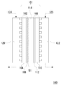
図1は本実施形態の燃料電池の構造を模式的に表した断面図である。触媒電極−固体電解質膜接合体101は、燃料極102、酸化剤極108、固体電解質膜114から構成される。燃料極102は基体104、触媒層106、および制限透過層181から構成される。酸化剤極108は基体110および触媒層112から構成される。上記複数の触媒電極−固体電解質膜接合体101が、燃料極側セパレータ120および酸化剤極側セパレータ122を介して電気的に接続され、燃料電池100が構成される。
【0043】
以上のように構成された燃料電池100において、各触媒電極−固体電解質膜接合体101の燃料極102には、燃料極側セパレータ120を介して燃料124が供給される。また、各触媒電極−固体電解質膜接合体101の酸化剤極108には、酸化剤極側セパレータ122を介して空気あるいは酸素などの酸化剤126が供給される。
【0044】
前記制限透過層181は、カーボンナノホーンを含む。
【0045】
本発明で用いるカーボンナノホーンは、カーボンナノチューブ同様、炭素原子の管状体部分を有する。しかし、カーボンナノホーンにおいてはカーボンナノチューブと異なり、チューブ径が一定ではなく、連続的に変化するため、空中円錐状の、すなわちホーン(角)上の構造を有する。ただし、ここで「円錐状」とは、厳密に幾何学的な定義のもとに限定されるものではない。カーボンナノホーンは、全体構造において、少なくとも一部の構造が先端部を頂点とし、チューブ形状部の径が連続的に変化している構造として特定され、先端部が折れ曲がっていてもいなくてもよい。
【0046】
本発明で用いるカーボンナノホーンは、単層カーボンナノホーンであっても複層カーボンナノホーンであってもよい。
【0047】
本発明のカーボンナノホーンの形状は、たとえば、軸方向の長さが10nm以上80nm以下、軸方向に直交する外径が1nm以上10nm以下、アスペクト比が50以下のものを用いることができる。ただし、ここでいうアスペクト比とは、軸に直行する径に対する軸方向の長さの比、すなわち(軸方向の長さ)/(外径)である。あるいは、上記カーボンナノホーンの一端が円錐形状で閉じており、該円錐の母線と母線のなす角が15°以上40°以下であるものを用いることができる。
【0048】
本発明で用いるカーボンナノホーンは、先端となる一端が閉じているものでも、閉じていないものでもよい。また、その一端の円錐形状の頂点が丸まった形状で終端していてもよい。
【0049】
また、本発明で用いるカーボンナノホーンは、構造の一部が不完全であり、微細孔を有するものでもよい。ここで、微細孔の開口径は、0.3nm以上5nm以下程度のものが考えられるが、特に限定されない。ここでの微細孔は、カーボンナノホーン集合体を含む薄層を作製した際に形成されるカーボンナノホーン集合体間のマクロな意味での孔、すなわち本発明における「細孔」とは異なる。
【0050】
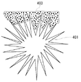
上記カーボンナノホーンは、たとえば図3に模式的に示すように、それぞれファンデルワールス力によって放射状に集合している。カーボンナノホーンが集合したもののことをカーボンナノホーン集合体401と呼ぶ。
【0051】
ここでいう集合とは、カーボンナノホーンに働くあらゆる力、例えばファンデルワールス力により複数のカーボンナノホーンが集まっている状態である。なお、ここでいう集合体とは、カーボンナノホーンを主とする炭素分子が集合した集合体を意味する。
【0052】
カーボンナノホーン集合体401はカーボンナノホーンが球状に集合したものが考えられる。ここでいう球状とは、必ずしも真球という意味ではなく、楕円形状、ドーナツ状等その他の様々な形状に集合しているものも含まれる。
【0053】
カーボンナノホーン集合体401が球状に近い場合には、その半径方向と、カーボンナノホーンの管状体の軸方向とが、ほぼ平行、平行に近い状態に集合している。すなわち、カーボンナノホーンの一端が、外側に突き出るように放射状の構造となってカーボンナノホーン集合体を形成している。このような特異な構造をとるため、非常に大きな比表面積を有するだけでなく、好適な量や種類、分散状態で触媒物質と電解質を一体化させた構造を形成することができる。なお、図3において、固体高分子電解質403はカーボンナノホーン集合体401の一部のみに設けられているように図示されているが、実際にはカーボンナノホーン集合体401全体に形成されている。
【0054】
また、カーボンナノホーン集合体の中心部ではカーボンナノホーン同士が化学的に結合している、またはカーボンナノチューブが蹴鞠のように丸まっているような形状も考えられるが、これら中心部の構造によって制限されるものではない。または、中心部が中空となっているものも考えられる。
【0055】
また、カーボンナノホーン集合体を構成するカーボンナノホーンが、その一端の円錐形状の頂点が丸まった形状で終端している場合、頂点が丸まった部分を外側に向けて放射状に集合している。
【0056】
本発明で用いるカーボンナノホーン集合体として、たとえば隣接する炭素分子の壁間距離が0.3nm以上1nm以下であり、外径が10nm以上200nm以下であるものを選ぶことができる。
【0057】
また、本発明で用いるカーボンナノホーン集合体は、カーボンナノチューブを含むことができる。
【0058】
さらに、上記カーボンナノホーン集合体は、複数の集合体が凝集して2次集合体を形成する場合がある。このような2次集合体が固体電解質に複数存在して薄層を構成する。しかし、これら2次集合体内部にも、集合体がばらばらに分散した形で固体高分子電解質と一体化している場合と同様、固体高分子電解質が侵入可能である。
【0059】
本発明に用いられるカーボンナノホーン集合体は、単にカーボンナノホーン集合体が混ざり合っているのではなく、カーボンナノホーン表面で互いに強固に融合または凝集して2次構造を構成したものを用いることができる。
【0060】
次に、本発明で用いるカーボンナノホーン集合体は、酸化処理、超音波処理、機械的な力、粉砕、酸処理、真空中熱処理などにより過剰のエネルギーを与えられた際に得られる。
【0061】
たとえば、本発明で用いるカーボンナノホーン集合体は、通常、不活性ガス雰囲気中、室温下で、グラファイト等の固体状炭素単体物質をターゲットとするレーザー蒸発法(レーザーアブレーション法)によって製造可能である。ここで、各炭素分子、あるいは、カーボンナノホーンの形状、径の大きさ、長さ、先端部の形状、炭素分子やカーボンナノホーン間の間隔、及び、炭素分子やカーボンナノホーン集合体間の細孔の大きさはレーザー蒸発法による製造条件や製造後の酸化処理等によって様々に制御することが可能である。
【0062】
レーザーアブレーション法では、固体状炭素物質に対して、不活性ガス雰囲気下でレーザー光を照射して炭素レーザーを蒸発させ、球状物質が集合した粉体をすす状物質として得る。さらに、得られたすす状物質としての粉体を、たとえば溶媒に懸濁することなどにより、単一もしくは複数個が集合した状態でのカーボンナノホーン集合体粒子を回収することができる。
【0063】
たとえば、Ar、He等の希ガスをはじめとする反応不活性ガス雰囲気中で、高出力CO2ガスレーザー光などのレーザー光を固体状炭素物質の表面に対し適当な角度で入射して行うことができる。レーザー光の出力は20W以上、パルス幅20ms以上500ms以下とすることができ、連続発振することが望ましい。また、照射角度は、前記固体状炭素物質表面と照射レーザー光との角度として100°以上170°以下、好ましくは120°以上140°以下の範囲とすることができる。照射時のレーザー光の固体状炭素物質表面へのスポット径は、たとえば0.5nm以上5nm以下とすることができる。さらに、炭素レーザー蒸発が行われる容器は、たとえば10−2Nm−2以下に減圧排気し、Arなどの反応不活性ガスによって103Nm−2以上105Nm−2以下とすることができる。また、固体状炭素物質としては、たとえば丸棒状焼結炭素や圧縮成形炭素等を用いることができる。
【0064】
得られたすす状物質は、適当な基板上に堆積して回収することや、ダストバッグによる微粒子回収の方法によって回収することができる。また、不活性ガスを反応容器内で流通させて、不活性ガスの流れにより前記すす状物質を回収することもできる。
【0065】
回収されたすす状物質は、カーボンナノホーン集合体を主として含み、たとえば、カーボンナノホーン集合体が90wt%以上含まれる物質として回収される。
【0066】
さらに、カーボンナノホーンに微細孔を付与するための酸化処理を施すことができる。酸化処理の方法には、たとえば、雰囲気、処理温度、処理時間等の処理条件を制御した加熱処理がある。ここで、雰囲気圧力は、使用するガス種によっても異なるが、例えば酸素分圧を0Torr以上760Torr以下程度の範囲で調節すること等が例示できる。処理温度については、250℃以上700℃以下程度の範囲で、さらには256℃以上600℃以下といった比較的低温の温度範囲で処理温度を制御することができる。このような酸化処理条件における処理時間は、0分以上120分以下程度の範囲で調整することができる。
【0067】
以上の酸化処理の条件を様々に制御することによって、炭素分子、あるいは、カーボンナノホーンの壁部および先端部に、任意の大きさの微細孔を開口することができる。なお、酸化処理は、上記温度範囲内の一定の温度で保持する一段階処理であってもよいし、上記温度範囲内の複数の温度で保持する多段階処理や、上記温度範囲内で処理温度を随時変化させる処理方法等も考慮することができる。さらには、上記方法以外にも、硝酸や過酸化水素等の酸化作用を有する酸溶液中でカーボンナノホーン集合体を加熱することで酸化処理を施すなどしても良い。
【0068】
酸化処理以外にも、集合体またはすす状物質として得られた粉体を液溶媒に懸濁させて超音波を照射することによって、単一もしくは複数個が集合した状態粒子を回収するとともに、集合体を形成するカーボンナノホーンに微細孔を形成することができる。分散溶媒としては、無機溶媒、炭化水素、有機溶媒等を用いることができる。
【0069】
上記カーボンナノホーン集合体を真空中で熱処理することにより、カーボンナノホーン集合体同士が強固に融合あるいは凝集した構造物を得ることができる。真空中での熱処理温度は特に限定されないが、たとえば、400℃以上2000℃以下とすることができる。
【0070】
上記カーボンナノホーンの集合体は、いずれも比表面積が大きく、かつ特異な表面形態をもつため、固体電解質型燃料電池において、燃料電池用電極の炭素物質としての機能と液体燃料の固体電解質膜側への移動を抑制する効果を付与することができる。
【0071】
本発明に係る燃料電池の燃料としては、液体有機燃料を用いることができる。前記制限透過層181を設けることにより、液体燃料のクロスオーバーを抑制しつつ電池効率の向上を図ることができ、本発明の効果が発揮される。
【0072】
また、前記制限透過層181は、さらに固体電解質を含むことができる。
【0073】
本発明における燃料電池における固体電解質膜は、燃料極102と酸化剤極108を隔てるとともに、両者の間で水素イオンや水分子を移動させる役割を有する。このため、固体電解質膜114は、水素イオンの伝導性が高い膜であることが好ましい。また、化学的に安定であって機械的強度が高いことが好ましい。固体電解質膜114を構成する材料としては、スルホン基、リン酸基、ホスホン基、ホスフィン基などの強酸基や、カルボキシル基などの弱酸基などの極性基を有する有機高分子が好ましく用いられる。こうした有機高分子として、スルフォン化ポリ(4−フェノキシベンゾイル−1,4−フェニレン)、アルキルスルフォン化ポリベンゾイミダゾールなどの芳香族含有高分子;ポリスチレンスルホン酸共重合体、ポリビニルスルホン酸共重合体、架橋アルキルスルホン酸誘導体、フッ素樹脂骨格およびスルホン酸からなるフッ素含有高分子などの共重合体;アクリルアミド−2−メチルプロパンスルフォン酸のようなアクリルアミド類とn−ブチルメタクリレートのようなアクリレート類とを共重合させて得られる共重合体;
スルホン基含有パーフルオロカーボン(ナフィオン(デュポン社製:登録商標)、アシプレックス(旭化成社製));カルボキシル基含有パーフルオロカーボン(フレミオンS膜(旭硝子社製:登録商標));などが例示される。このうち、スルフォン化ポリ(4−フェノキシベンゾイル−1,4−フェニレン)、アルキルスルフォン化ポリベンゾイミダゾールなどの芳香族含有高分子を選択した場合、有機液体燃料の透過を抑制でき、クロスオーバーによる電池効率の低下を抑えることができる。
【0074】
図2は燃料極102、酸化剤極108、固体電解質膜114および制限透過層181の構造を模式的に表した断面図である。図のように、本実施形態における燃料極102および酸化剤極108は、たとえば、触媒を担持した炭素粒子と固体高分子電解質の微粒子とを含むことができ、触媒層106、触媒層112を基体104、基体110上に形成した構成となっている。基体表面は撥水処理してもよい。
【0075】
基体104および基体110としては、カーボンペーパー、カーボンの成形体、カーボンの焼結体、焼結金属、発泡金属などの多孔性基体を用いることができる。また、基体の撥水処理にはポリテトラフルオロエチレンなどの撥水剤を用いることができる。
【0076】
燃料極102の触媒としては、白金、白金とルテニウム、金、レニウムなどとの合金、ロジウム、パラジウム、イリジウム、オスミウム、ルテニウム、レニウム、金、銀、ニッケル、コバルト、リチウム、ランタン、ストロンチウム、イットリウムなどが例示される。一方、酸化剤極108の触媒としては、燃料極102の触媒と同様のものが用いることができ、上記例示物質を使用することができる。なお、燃料極102および酸化剤極108の触媒は同じものを用いても異なるものを用いてもよい。
【0077】
触媒を担持する炭素粒子としては、アセチレンブラック(デンカブラック(電気化学社製:登録商標)、XC72(Vulcan社製)など)、ケッチェンブラック、アモルファスカーボン、カーボンナノチューブ、カーボンナノホーンなどが例示される。炭素粒子の粒径は、たとえば、0.01μm以上0.1μm以下、好ましくは0.02μm以上0.06μm以下とする。
【0078】
また、本発明の触媒電極の構成成分である固体高分子電解質は、触媒電極表面において、触媒を担持した炭素粒子と固体電解質膜114を電気的に接続するとともに触媒表面に有機液体燃料を到達させる役割を有しており、水素イオン伝導性や水移動性が要求され、さらに、燃料極102においてはメタノール等の有機液体燃料透過性が求められ、酸化剤極108においては酸素透過性が求められる。固体高分子電解質としてはこうした要求を満たすために、水素イオン伝導性や、メタノール等の有機液体燃料透過性に優れる材料が好ましく用いられる。具体的には、スルホン基、リン酸基などの強酸基や、カルボキシル基などの弱酸基などの極性基を有する有機高分子が好ましく用いられる。こうした有機高分子として、スルホン基含有パーフルオロカーボン(ナフィオン(デュポン社製)、アシプレックス(旭化成社製)など);カルボキシル基含有パーフルオロカーボン(フレミオンS膜(旭硝子社製)など);
ポリスチレンスルホン酸共重合体、ポリビニルスルホン酸共重合体、架橋アルキルスルホン酸誘導体、フッ素樹脂骨格およびスルホン酸からなるフッ素含有高分子などの共重合体;アクリルアミド−2−メチルプロパンスルフォン酸のようなアクリルアミド類とn−ブチルメタクリレートのようなアクリレート類とを共重合させて得られる共重合体;などが例示される。
【0079】
また、極性基の結合する対象の高分子としては他に、ポリベンズイミダゾール誘導体、ポリベンズオキサゾール誘導体、ポリエチレンイミン架橋体、ポリサイラミン誘導体、ポリジエチルアミノエチルポリスチレン等のアミン置換ポリスチレン、ジエチルアミノエチルポリメタクリレート等の窒素置換ポリアクリレート等の窒素または水酸基を有する樹脂;シラノール含有ポリシロキサン、ヒドロキシエチルポリメチルアクリレートに代表される水酸基含有ポリアクリル樹脂;パラヒドロキシポリスチレンに代表される水酸基含有ポリスチレン樹脂;などを用いることもできる。
【0080】
また、上記した高分子に対して、適宜、架橋性の置換基、例えば、ビニル基、エポキシ基、アクリル基、メタクリル基、シンナモイル基、メチロール基、アジド基、ナフトキノンジアジド基を導入してもよい。
【0081】
燃料極102および酸化剤極に108おける上記の固体高分子電解質は、同一のものであっても異なるものであってもよい。
【0082】
次に、本発明の固体電解質型燃料電池の製造方法について詳細に説明する。
【0083】
本発明における燃料極および酸化剤極の作製方法は特に制限がないが、たとえば以下のようにして作製することができる。
【0084】
まず燃料極および酸化剤極の触媒の炭素粒子への担持は、一般的に用いられている含浸法によって行うことができる。次に触媒を担持させた炭素粒子と上記固体高分子電解質粒子を溶媒に分散させ、ペースト状とした後、これを基体に塗布、乾燥させることによって燃料極および酸化剤極を得ることができる。ここで、炭素粒子の粒径は、たとえば0.01μm以上0.1μm以下とする。触媒粒子の粒径は、たとえば1nm以上10nm以下とする。また、第一および第二の固体高分子電解質粒子の粒径は、たとえば0.05μm以上1μm以下とする。炭素粒子と固体高分子電解質粒子とは、たとえば、重量比で2:1〜40:1の範囲で用いられる。また、ペースト中の水と溶質との重量比は、たとえば、1:2〜10:1程度とする。基体へのペーストの塗布方法については特に制限がないが、たとえば、刷毛塗り、スプレー塗布、およびスクリーン印刷等の方法を用いることができる。ペーストは、たとえば約1μm以上2mm以下の厚さで塗布される。ペーストを塗布した後、使用するフッ素樹脂に応じた加熱温度および加熱時間で加熱し、燃料極または酸化剤極が作製される。加熱温度および加熱時間は、用いる材料によって適宜に選択されるが、たとえば、加熱温度100℃以上250℃以下、加熱時間30秒以上30分以下とすることができる。
【0085】
本発明における固体電解質膜は、用いる材料に応じて適宜な方法を採用して作製することができる。たとえば固体電解質膜を有機高分子材料で構成する場合、有機高分子材料を溶媒に溶解ないし分散した液体を、ポリテトラフルオロエチレン等の剥離性シート等の上にキャストして乾燥させることにより得ることができる。
【0086】
さらに、触媒電極の触媒層(ペースト塗布面)、もしくは固体電解質膜表面、に制限透過層を付与させる。たとえば、触媒電極の触媒層に上記カーボンナノホーンを含む制限透過層を付与することができ、この場合、少なくとも一つの電極について付与されればよい。また、たとえば、固体電解質膜表面に上記カーボンナノホーンを含む制限透過層を付与する場合、少なくとも片面に付与されればよい。
【0087】
上記制限透過層の付与は、たとえば以下のようにして行うことができる。上に記載のカーボンナノホーン(ここではカーボンナノホーン集合体)および固体電解質を溶媒に分散させ、ペースト状とした後、これを基体に塗布、乾燥させることによって燃料極および酸化剤極を得ることができる。ここで、前記固体高分子電解質は、粒子状とすることができ、粒子径は触媒電極に用いた固体電解質と等しくても異なってもよく、たとえば0.05μm以上0.5μm以上とする。上記制限透過層中のカーボンナノホーン量は、重量比でたとえば1%以上、好ましくは30%以上とする。1%以上とすることで、液体燃料の浸透を効果的に制限することができる。さらに、上記制限透過層中の前記カーボンナノホーン量は、重量比でたとえば95%以下、好ましくは99.5%以下とすることができる。99.5%以下とすることで、上記制限透過層中の水素イオンの伝導性も良好に保つことができる。上記制限透過層中のペースト中の水と溶質との重量比は、たとえば、1:2〜10:1程度とすることができる。
【0088】
上に記載の固体電解質は、たとえば、前記触媒電極または固体電解質膜に用いることができる物質から選ぶことができる。
【0089】
ここで、クロスオーバー抑制の観点からは、固体電解質を、有機液体燃料の透過性の低い材料を用いることが好ましい。たとえば、スルフォン化ポリ(4−フェノキシベンゾイル−1,4−フェニレン)、アルキルスルフォン化ポリベンゾイミダゾールなどの芳香族縮合系高分子とすることが好ましい。
【0090】
触媒電極表面もしくは固体電解質膜表面へのペーストの塗布方法については特に制限がないが、たとえば、刷毛塗り、スプレー塗布、およびスクリーン印刷等の方法を用いることができる。ペーストを塗布した後、加熱乾燥することにより上記カーボンナノホーンを含む薄層を制限透過層として有する触媒電極、もしくは上記カーボンナノホーンを含む薄層を制限透過層として有する固体電解質膜が作製される。
【0091】
ここで、上記制限透過層(ここではカーボンナノホーンを含む薄層)は、たとえば厚さ1nm以上、好ましくは10nm以上とすることができる。1nm以上とすることにより、液体燃料の浸透を効果的に制限することができる。さらに、上記制限透過層の厚さはたとえば1000nm以下、好ましくは500nm以下とすることができる。1000nm以下とすることで、上記制限透過層中の水素イオンの伝導性も良好に保つことができる。加熱温度および加熱時間は、用いる材料によって適宜に選択されるが、たとえば、加熱温度100℃以上〜250℃以下、加熱時間30秒以上30分以下とすることができる。
【0092】
以上のようにして作製した固体電解質膜を、燃料極および酸化剤極で挟み、ホットプレスし、電極−電解質接合体を得る。このとき、両電極の触媒が設けられた面と固体電解質膜とが接するようにする。ホットプレスの条件は、材料に応じて選択されるが、固体電解質膜や電極表面の電解質膜を軟化点やガラス転移のある有機高分子で構成する場合、これらの高分子の軟化温度やガラス転移位温度を超える温度とすることができる。具体的には、例えば、温度100℃以上250℃以下、圧力1kg/cm2以上100kg/cm2以下、時間10以上300秒以下とする。
【0093】
以上により、触媒電極と固体電解質膜との間に、カーボンナノホーン(ここではカーボンナノホーン集合体)を含む制限透過層が形成された、固体電解質型燃料電池を得ることができる。上記固体電解質型燃料電池においては、カーボンナノホーン集合体に特異的な微細構造により、燃料極に供給された液体燃料の固体電解質膜への移動を抑制し、優れた電池特性を有するものである。
【0094】
なお、上記制限透過層は、少なくとも一つの触媒電極と固体電解質膜との間に形成されていればよい。
【0095】
メタノール透過性は、以下のように測定することができる。被測定電解質膜(膜厚50μm、面積1cm平方)で隔てられた液体容器に、片側99.5%メタノール50ccを入れ、反対側に純水50ccを入れ、それぞれの液体が蒸発しないように密閉する。純水中に被測定電解質膜を透過してくるメタノールの濃度の時間変化をガスクロマトグラフで測定してメタノール透過量を決めることができる。
【0096】
また、薄層の細孔径分布は、たとえばガス透過法、水銀圧入法、などの方法により測定することができる。
【0097】
【実施例】
以下に本発明のカーボンナノホーン集合体を固体高分子電解質と触媒担持炭素微粒子からなる触媒電極と固体高分子電解質膜との界面に用いた固体高分子型燃料電池を実施例によって具体的に説明するが、本発明はこれらに限定されない。
【0098】
〔実施例1〕
ルテニウム-白金合金を担持したケッチェンブラック100mgにアルドリッチ社製5%ナフィオン溶液を加え、超音波混合器で50℃にて3時間攪拌して触媒ペーストとした。上で用いた合金組成は50atom%Ruで、合金と炭素微粉末の重量比は1:1とした。このペーストを10cm×10cmのカーボンペーパー(TGP−H−120;東レ社製)上に2mg/cm2塗布し、120℃で乾燥させ、触媒電極とした。
【0099】
カーボンナノホーン集合体はレーザーアブレーション法により作製した。すなわち、固体状炭素物質としての焼結丸棒炭素を真空容器内に設置し、容器内を10−2Paにまで減圧排気した後、Arガスを760Torrの雰囲気圧となるように導入した。次いで、高出力のCO2レーザー光を前記固体状炭素物質に室温中、30分照射した。前記レーザーの出力は100W、パルス幅20msの連続発振とし、固体状炭素物質表面とのなす角が120°となるよう照射した。これにより得られたすす状物質を透過型電子顕微鏡(TEM)により観察したところ、カーボンナノホーン集合体構造であることが確認された。
【0100】
得られたすす状物質をエタノール中で超音波処理(400kHz、60分)とデカンテーションを4回繰り返し行うことにより、単一また数個の粒子からなるカーボンナノホーン集合体を得ることができた。
【0101】
得られたカーボンナノホーン集合体の粒子径は、粒子のTEM観察より10nm以上100nm以下の範囲であった。
【0102】
カーボンナノホーン集合体100mgに1%ナフィオン溶液10mlを加えて超音波混合器で50℃にて3時間攪拌後、前記触媒電極の触媒層表面に、乾燥後重量が0.1mg/cm2になるように触媒膜表面に塗布し、120℃で乾燥した。これを触媒電極−制限透過層複合体とした。前記触媒電極−制限透過層複合体の断面を走査型電子顕微鏡(SEM)観察したところ、カーボンナノホーン集合体層は、厚さが100nmであった。
【0103】
上記触媒電極−制限透過層複合体をナフィオン117(デュポン社製:登録商標)膜の両面に120℃で熱圧着し、得られた触媒電極−固体電解質膜接合体を燃料電池セルとした。
【0104】
この燃料電池セルに燃料として10v/v%メタノール水溶液と酸素ガスをそれぞれ2cc/min、30cc/min供給し、電池特性を測定したところ、電流密度100mA/cm2時の電池電圧が0.43Vとなった。この特性は12時間経過後も変化が見られなかった。さらに、本発明による燃料電池セルは30%以上の濃度でもほとんど出力の低下は見られなかった。
【0105】
〔実施例2〕
実施例1と同様の方法で触媒電極を作製した。次に、実施例1と同様にして作製したカーボンナノホーン集合体100mgに1%ナフィオン溶液10mlに加え、超音波混合器50℃にて3時間で攪拌した。これを、ナフィオン117(デュポン社製)膜の片面に乾燥後重量が0.1mg/cm2になるように塗布し、50℃で乾燥させ、カーボンナノホーン集合体−固体電解質膜複合体を作製した。走査型電子顕微鏡(SEM)観察したところ、カーボンナノホーン集合体層の膜厚は100nmであった。このカーボンナノホーン集合体−固体電解質膜複合体に、上で得られた触媒電極を120℃にて熱圧着し、燃料電池セルとした。
【0106】
この燃料電池セルに、燃料として10v/v%メタノール水溶液と酸素ガスをそれぞれ2cc/min、30cc/min供給し、電池特性を測定した。ここで、カーボンナノホーン集合体を塗布した側にメタノール水溶液を供給した。このとき、電流密度100mA/cm2時の電池電圧が0.42Vであり、この特性は12時間経過後も変化が見られなかった。
【0107】
〔比較例1〕
実施例1、2と同様の方法で触媒電極を作製した。得られた触媒電極をナフィオン117(デュポン社製)膜の両面に120℃で熱圧着し、得られた触媒電極−固体電解質膜接合体を燃料電池セルとした。この燃料電池セルに燃料として10v/v%メタノール水溶液と酸素ガスをそれぞれ2cc/min、30cc/min供給し、電池特性を測定したところ、電流密度100mA/cm2時の電池電圧は0.3Vであった。また、メタノール濃度が30v/v%を越えると著しく出力が低下した。
【0108】
以上の各実施例および比較例から、本発明により電池特性が大幅に向上することが明らかになった。すなわち、本発明による実施例では、燃料電池に設けた制限透過層中に存在するカーボンナノホーンの特異なパッキング構造により、優れたメタノールの透過制限能を得るとともに、前記カーボンナノホーンの空隙に固体電解質による水素イオン伝導路が好適に形成され、水素イオン伝導性を良好に維持できることが明らかになった。
【0109】
【発明の効果】
以上説明したように本発明によれば、触媒電極と固体電解質膜との間に、液体燃料の透過を制限し、カーボンナノホーンを含む制限透過層を設けているため、電極表面における水素イオン伝導性を良好に維持しつつ有機液体燃料のクロスオーバーを抑制することができる。このため、電池特性の向上および電池の信頼性を向上させることができる。
【図面の簡単な説明】
【図1】本発明の燃料電池の構造の一例を模式的に表した断面図である。
【図2】本発明の燃料電池の一例における燃料極、酸化剤極、固体電解質膜、および制限透過層を模式的に表した断面図である。
【図3】本発明の燃料電池において用いることができる、少なくともカーボンナノホーン集合体および固体電解質を含む複合電解質の基本構造の一例を示す図である。
【符号の説明】
100 燃料電池
101 触媒電極−固体電解質膜接合体
102 燃料極
104 基体
106 触媒層
108 酸化剤極
110 基体
112 触媒層
114 固体電解質膜
120 燃料極側セパレータ
122 酸化剤極側セパレータ
124 燃料
126 酸化剤
181 制限透過層
401 カーボンナノホーン集合体
403 固体高分子電解質[0001]
BACKGROUND OF THE INVENTION
The present invention relates to a fuel cell, a fuel cell electrode, a solid electrolyte membrane for a fuel cell, and a method for producing the same, and more particularly to a fuel cell in which liquid fuel is supplied to a fuel electrode.
[0002]
[Prior art]
A polymer electrolyte fuel cell has a solid electrolyte membrane such as a perfluorosulfonic acid membrane as an electrolyte, and a fuel electrode and an oxidant electrode joined to both sides of the membrane. Hydrogen is added to the fuel electrode and oxygen is added to the oxidant electrode. It is a device that supplies and generates electricity by electrochemical reaction.
The following electrochemical reactions occur at each electrode.
Fuel electrode: H2→ 2H++ 2e−
Oxidant electrode: 1 / 2O2+ 2H++ 2e−→ H2O
[0003]
By this reaction, the polymer electrolyte fuel cell is 1 A / cm at normal temperature and normal pressure.2The above high output can be obtained.
[0004]
The fuel electrode and the oxidant electrode are provided with a mixture of carbon particles carrying a catalyst material and a solid polymer electrolyte. In general, the mixture is applied on an electrode substrate such as carbon paper that serves as a fuel gas diffusion layer. A fuel cell is constructed by sandwiching a solid electrolyte membrane between these two electrodes and thermocompression bonding.
[0005]
In the fuel cell having this configuration, the hydrogen gas supplied to the fuel electrode passes through the pores in the electrode, reaches the catalyst, emits electrons, and becomes hydrogen ions. The emitted electrons are guided to the external circuit through the carbon particles in the fuel electrode and the electrode substrate, and flow into the oxidant electrode from the external circuit.
[0006]
On the other hand, hydrogen ions generated in the fuel electrode reach the oxidant electrode through the solid polymer electrolyte in the fuel electrode and the solid electrolyte membrane disposed between the two electrodes, and oxygen supplied to the oxidant electrode and an external circuit It reacts with more flowing electrons to produce water as shown in the above reaction formula. As a result, in the external circuit, electrons flow from the fuel electrode toward the oxidant electrode, and electric power is taken out.
[0007]
In order to improve the characteristics of the fuel cell configured as described above, it is important that the adhesion between the electrode and the solid electrolyte membrane is good. That is, the conductivity of hydrogen ions generated by the electrode reaction is required to be high at the interface between the two. If the adhesion at the interface is poor, the conductivity of hydrogen ions is reduced, the electrical resistance is increased, and this causes a decrease in battery efficiency.
[0008]
Although the fuel cell using hydrogen as the fuel has been described above, research and development of a fuel cell using an organic liquid fuel such as methanol has been actively conducted in recent years.
[0009]
Fuel cells that use organic liquid fuels can be used without reforming organic liquid fuels, such as those that reform organic liquid fuels into hydrogen gas and use them as fuel, and direct methanol fuel cells. Those that supply directly to the fuel electrode are known.
[0010]
In particular, the fuel cell that directly supplies the organic liquid fuel to the fuel electrode without reforming has a structure for supplying the organic liquid fuel directly to the fuel electrode, and thus does not require a device such as a reformer. Therefore, the configuration of the battery can be simplified, and the entire apparatus can be reduced in size. Moreover, compared with gaseous fuels, such as hydrogen gas and hydrocarbon gas, the organic liquid fuel also has the characteristic that it can be conveyed easily and safely.
[0011]
In general, in a fuel cell using an organic liquid fuel, a solid electrolyte membrane made of a solid polymer ion exchange resin is used as an electrolyte. Here, in order for the fuel cell to function, it is necessary for hydrogen ions to move through the membrane from the fuel electrode to the oxidant electrode, and it is known that this movement of hydrogen ions involves the movement of water. Therefore, it is necessary that the film contains a certain amount of moisture.
[0012]
However, when an organic liquid fuel such as methanol having a high affinity for water is used, the organic liquid fuel diffuses into the solid electrolyte membrane containing moisture, and further reaches the oxidant electrode (crossover). There was a problem to be overcome. This crossover causes an organic liquid fuel that should originally provide electrons at the fuel electrode to be oxidized on the oxidant electrode side and is not used effectively as a fuel, thus causing a decrease in voltage and output, and a decrease in fuel efficiency.
[0013]
In order to improve the characteristics of such a solid oxide fuel cell, the diffusibility of the gas used for the reaction in the electrode is high, and the conductivity of hydrogen ions and electrons generated by the electrode reaction is high. In addition, it is necessary to prevent the fuel substance from moving in the solid electrolyte membrane toward the oxidant electrode.
[0014]
[Problems to be solved by the invention]
In view of the above circumstances, the technical problem of the present invention is to provide a structure that suppresses the movement of liquid fuel to a solid electrolyte membrane without impairing the conductivity of hydrogen ions generated in the catalyst electrode reaction of the fuel electrode. An object of the present invention is to provide a fuel cell having an electrolyte membrane and a method for manufacturing the fuel cell.
[0015]
The present invention suppresses the permeation of organic liquid fuel while maintaining good hydrogen ion conductivity in the catalyst electrode, and suppresses crossover of the organic liquid fuel, thereby improving battery characteristics and battery reliability. It aims to plan.
[0016]
[Means for Solving the Problems]
According to the present invention, there is provided a fuel cell including a fuel electrode, an oxidant electrode, and a solid electrolyte membrane sandwiched between the fuel electrode and the oxidant electrode, wherein liquid fuel is supplied to the fuel electrode, Between the fuel electrode or the oxidant electrode and the solid electrolyte membrane,Limits permeation of the liquid fuel and includes carbon nanohornsThere is provided a fuel cell comprising a restricted permeation layer.
[0017]
According to the present invention, between the fuel electrode or oxidant electrode and the solid electrolyte membrane,Limits the permeation of liquid fuel and includes carbon nanohornsSince the restricted permeation layer is provided, liquid fuel crossover can be effectively prevented. As the restricted permeation layer, those having various configurations can be adopted, and those having excellent ability to restrict the permeation of liquid fuel and good conductivity of hydrogen ions are preferably used.
[0018]
In the above fuel cell, the limited permeation layerIs, Including carbon nanohornMuThe carbon nanohorn in the present invention is a tubular body in which one end of a carbon nanotube has a conical shape. The carbon nanohorns are aggregated in a configuration in which the conical portions protrude from the surface like horns (horns) around the tube side by van der Waals forces acting between the conical portions to form a carbon nanohorn aggregate. . The diameter of the carbon nanohorn aggregate is 120 nm or less, typically about 10 nm to 100 nm. In addition, each nanotube of the carbon nanohorn aggregate has a diameter of about 2 nm and a length of about 30 nm to about 50 nm, and the cone portion has an average inclination angle of an axial section of about 20 °.
[0019]
The carbon nanohorn aggregate having such a unique structure and having a distribution in particle diameter forms a dense and dense packing structure by packing the projections of the nanohorn. Since the densified carbon nanohorn aggregate has an action of inhibiting the penetration of liquid, a thin layer of the carbon nanohorn aggregate is provided between the catalyst electrode and the solid electrolyte membrane, so that the liquid can be obtained using this inhibitory action. Permeation of the solid electrolyte membrane of fuel can be suppressed. According to the present invention, the crossover is suppressed by the action of the carbon nanohorn, the leakage of the liquid fuel to the oxidant electrode can be prevented, and the decomposition of the liquid fuel at the oxidant electrode can be suppressed. Thereby, the fall of a battery voltage can be suppressed and an energy density can be improved.
[0020]
Here, in order to suppress the permeation of liquid fuel, it is also conceivable that the limited permeation layer is constituted by carbon particles and a solid electrolyte membrane, and the permeation of liquid fuel is suppressed by the carbon particles. In this case, it is necessary to increase the permeation limiting ability of the liquid fuel by increasing the filling rate of the carbon particles in the limited permeation layer in which the carbon particles are miniaturized. However, when the particles are made finer in this way, the conductivity of hydrogen ions is hindered and the efficiency of the battery is lowered. In this respect, since the fuel cell having the above-described structure includes a layer containing a substance having a unique structure called carbon nanohorn, the conductivity of hydrogen ions can be secured and the permeation of liquid fuel can be effectively limited. Although it is not always clear why the carbon nanohorn can be used to achieve both hydrogen ion conductivity and liquid fuel permeation limiting ability, the carbon nanohorn is present in a properly packed state in the layer, and the solid electrolyte is present in the void. This is presumably because the hydrogen ion conduction path is suitably formed.
[0021]
In the present invention, the restricted permeation layer may further include a solid electrolyte. By doing so, a hydrogen ion conduction path by the solid electrolyte is suitably formed in the gap of the carbon nanohorn existing in the restricted permeation layer, and excellent liquid fuel permeation restriction ability is obtained while maintaining good hydrogen ion conductivity. be able to.
[0022]
According to the present invention, a substrate, a catalyst layer formed on the substrate and including at least catalyst-supporting carbon particles and a solid polymer electrolyte, and formed on the catalyst layer,Suppresses the permeation of liquid fuel and contains carbon nanohornsThere is provided a fuel cell catalyst electrode comprising a restricted permeation layer.
[0023]
According to the present invention, on the catalyst layer,Suppresses the permeation of liquid fuel and contains carbon nanohornsSince the restricted permeation layer is provided, it is possible to effectively prevent liquid fuel crossover by contacting the solid electrolyte membrane in the fuel cell. As the limiting permeation layer, the same one as in the case of the fuel cell can be used.
[0024]
The catalyst electrode for a fuel cell of the present invention contains carbon nanohorns in the restricted permeation layer.Mu
[0025]
According to the catalyst electrode for a fuel cell of the present invention, by providing a thin layer structure containing a substance having a unique structure called carbon nanohorn, conductivity of hydrogen ions is ensured and liquid fuel permeates to the oxidant side. It is possible to effectively limit what is done.
[0026]
Further, the fuel cell catalyst electrode of the present invention may be configured to further include a solid electrolyte in the restricted permeation layer. By doing so, a hydrogen ion conduction path by the solid electrolyte is suitably formed in the gap of the carbon nanohorn existing in the restricted permeation layer, and excellent liquid fuel permeation restriction ability is obtained while maintaining good hydrogen ion conductivity. be able to.
[0027]
According to the present invention, comprising a membrane mainly composed of a solid electrolyte, and a restricted permeable layer provided on at least one surface of the membrane for restricting permeation of liquid fuel, the restricted permeable layer comprises:Including carbon nanohornA solid electrolyte membrane for a fuel cell is provided.
[0028]
According to the present invention, at least one surface of the solid electrolyte membrane is provided with a restricted permeable layer that restricts the permeation of liquid fuel, and the restricted permeable layer comprises:Including carbon nanohornTherefore, liquid fuel crossover can be effectively prevented by contacting the catalyst electrode in the fuel cell. As the limiting permeation layer, the same one as in the case of the fuel cell or the fuel cell catalyst electrode can be used.
[0029]
The solid electrolyte membrane for a fuel cell according to the present invention includes carbon nanohorns in the limited transmission layer.Mu
[0030]
According to the solid electrolyte membrane for a fuel cell of the present invention, by providing a thin layer structure containing a substance having a unique structure called carbon nanohorn, conductivity of hydrogen ions is ensured, and liquid fuel is on the oxidant side. It is possible to effectively limit the transmission.
[0031]
Moreover, the solid electrolyte membrane for a fuel cell of the present invention may be configured to further include a solid electrolyte in the restricted permeation layer.
[0034]
According to the present invention, there is provided a method for producing a fuel cell electrode in which a catalyst layer is provided on a substrate, the coating liquid containing conductive particles carrying a catalyst substance and particles containing a solid polymer electrolyte, A step of coating the substrate to form the catalyst layer, and a step of coating the surface of the catalyst layer with a dispersion containing carbon nanohorns to form a liquid fuel restricted permeation layer. A method of manufacturing a fuel cell electrode is provided.
[0035]
Further, in the present invention, after obtaining the fuel cell electrode by the method for producing a fuel cell electrode, the fuel cell electrode is brought into contact with the restricted permeation layer and the solid electrolyte membrane. There is provided a method for manufacturing a fuel cell, comprising a step of pressure-bonding the solid electrolyte membrane.
[0036]
According to the present invention, there is provided a fuel cell comprising a step of applying a dispersion containing carbon nanohorns to at least one surface of a membrane mainly composed of a solid electrolyte to form a restricted permeation layer for liquid fuel. A method for producing a solid electrolyte membrane is provided.
[0037]
Further, according to the present invention, a process for obtaining an electrolyte membrane for a fuel cell by the above-described method for producing a solid electrolyte membrane for a fuel cell, and a coating containing particles containing conductive particles carrying a catalyst substance and a solid polymer electrolyte The fuel is applied in a state in which a catalyst electrode is formed by applying a liquid on a substrate to form a catalyst layer, the restricted permeation layer of the electrolyte membrane for a fuel cell, and the catalyst layer are in contact with each other. There is provided a method for producing a fuel cell comprising the step of pressure-bonding a solid electrolyte membrane for a battery and the catalyst electrode.
[0038]
According to the manufacturing method of the present invention, a fuel cell excellent in hydrogen ion conductivity and liquid fuel permeation limiting ability can be stably manufactured.
[0039]
The fuel cell obtained by the above manufacturing method can have a structure containing carbon nanohorns. By carrying out like this, by providing the thin layer structure containing the substance which has a peculiar structure called carbon nanohorn between the catalyst layer of at least one catalyst electrode, and a solid electrolyte membrane, crossover is suppressed and an oxidizing agent The leakage of the liquid fuel to the electrode can be prevented, and the decomposition of the liquid fuel at the oxidant electrode can be suppressed. Thereby, the fall of a battery voltage can be suppressed and an energy density can be improved.
[0040]
In the fuel cell manufacturing method of the present invention, the limited permeation layer may further include a solid electrolyte. By doing so, a hydrogen ion conduction path by the solid electrolyte is suitably formed in the gap of the carbon nanohorn existing in the restricted permeation layer, and excellent liquid fuel permeation restriction ability is obtained while maintaining good hydrogen ion conductivity. be able to.
[0041]
DETAILED DESCRIPTION OF THE INVENTION
The fuel cell in the present invention includes a fuel electrode, an oxidant electrode, and an electrolyte layer. The fuel electrode and the oxidizer electrode are collectively referred to as a catalyst electrode. A limiting permeation layer is provided between the fuel electrode and the electrolyte layer. Here, the restricted permeation layer is a layer that restricts the movement of the liquid fuel supplied to the fuel electrode side.
[0042]
FIG. 1 is a cross-sectional view schematically showing the structure of the fuel cell of this embodiment. The catalyst electrode-solid
[0043]
In the
[0044]
The
[0045]
The carbon nanohorn used in the present invention has a tubular body portion of carbon atoms like the carbon nanotube. However, unlike carbon nanotubes, carbon nanohorns have a structure that is conical in air, that is, on a horn (corner), because the tube diameter is not constant and varies continuously. However, the term “conical” is not limited to a strictly geometric definition. The carbon nanohorn is specified as a structure in which at least a part of the structure has a tip portion at the top and the diameter of the tube-shaped portion continuously changes, and the tip portion may or may not be bent.
[0046]
The carbon nanohorn used in the present invention may be a single-layer carbon nanohorn or a multi-layer carbon nanohorn.
[0047]
As the shape of the carbon nanohorn of the present invention, for example, one having an axial length of 10 nm to 80 nm, an outer diameter orthogonal to the axial direction of 1 nm to 10 nm, and an aspect ratio of 50 or less can be used. However, the aspect ratio here is the ratio of the length in the axial direction to the diameter perpendicular to the axis, that is, (length in the axial direction) / (outer diameter). Alternatively, one having one end of the carbon nanohorn closed in a conical shape, and an angle formed by the generatrix and the generatrix can be 15 ° or more and 40 ° or less.
[0048]
The carbon nanohorn used in the present invention may be closed at one end or may not be closed. Moreover, you may terminate in the shape where the vertex of the cone shape of the one end was round.
[0049]
In addition, the carbon nanohorn used in the present invention may have an incomplete structure and have fine pores. Here, the opening diameter of the fine holes may be about 0.3 nm to 5 nm, but is not particularly limited. The micropores here are different from the macropores between the carbon nanohorn aggregates formed when a thin layer containing the carbon nanohorn aggregates is produced, that is, the “pores” in the present invention.
[0050]
The carbon nanohorns are gathered radially by van der Waals forces, for example, as schematically shown in FIG. A collection of carbon nanohorns is called a
[0051]
The term “aggregation” used herein refers to a state in which a plurality of carbon nanohorns are gathered by any force acting on the carbon nanohorns, for example, van der Waals force. Here, the aggregate means an aggregate in which carbon molecules mainly including carbon nanohorns are aggregated.
[0052]
The carbon nanohorn aggregate 401 may be a carbon nanohorn aggregated in a spherical shape. The term “spherical” as used herein does not necessarily mean a true sphere, but includes a collection of various shapes such as an elliptical shape and a donut shape.
[0053]
When the
[0054]
In addition, the shape of the carbon nanohorn aggregate in which the carbon nanohorns are chemically bonded to each other or the carbon nanotubes are rounded like a kick is also conceivable, but is limited by the structure of these central portions. It is not a thing. Or what has a hollow center part is also considered.
[0055]
Moreover, when the carbon nanohorn which comprises a carbon nanohorn aggregate | assembly is terminated with the shape where the vertex of the conical shape of the one end was rounded, the part where the vertex rounded is gathered radially toward the outer side.
[0056]
As the carbon nanohorn aggregate used in the present invention, for example, a carbon nanohorn aggregate having a distance between adjacent carbon molecules of 0.3 nm to 1 nm and an outer diameter of 10 nm to 200 nm can be selected.
[0057]
Moreover, the carbon nanohorn aggregate used in the present invention can contain carbon nanotubes.
[0058]
Furthermore, in the carbon nanohorn aggregate, a plurality of aggregates may aggregate to form a secondary aggregate. A plurality of such secondary assemblies are present in the solid electrolyte to form a thin layer. However, the solid polymer electrolyte can also enter the secondary assemblies as in the case where the assemblies are integrated with the solid polymer electrolyte in a dispersed manner.
[0059]
The carbon nanohorn aggregate used in the present invention is not simply a mixture of carbon nanohorn aggregates, but a carbon nanohorn aggregate that is firmly fused or aggregated on the surface of the carbon nanohorn to form a secondary structure can be used.
[0060]
Next, the carbon nanohorn aggregate used in the present invention is obtained when excess energy is applied by oxidation treatment, ultrasonic treatment, mechanical force, pulverization, acid treatment, heat treatment in vacuum, or the like.
[0061]
For example, the carbon nanohorn aggregate used in the present invention can be usually produced by a laser evaporation method (laser ablation method) using a solid carbon simple substance such as graphite as a target in an inert gas atmosphere at room temperature. Here, the shape of each carbon molecule or carbon nanohorn, the size of the diameter, the length, the shape of the tip, the spacing between the carbon molecules and the carbon nanohorns, and the pores between the carbon molecules and the carbon nanohorn aggregates The size can be controlled variously according to the manufacturing conditions by the laser evaporation method and the oxidation treatment after the manufacturing.
[0062]
In the laser ablation method, a solid carbon material is irradiated with laser light in an inert gas atmosphere to evaporate the carbon laser, and a powder in which spherical materials are aggregated is obtained as a soot-like material. Furthermore, by suspending the obtained powder as the soot-like substance in, for example, a solvent, the carbon nanohorn aggregate particles in a state in which a single substance or a plurality are aggregated can be recovered.
[0063]
For example, in a reaction inert gas atmosphere including rare gases such as Ar and He, high output CO2Laser light such as gas laser light can be incident on the surface of the solid carbon material at an appropriate angle. The output of the laser light can be 20 W or more, the pulse width can be 20 ms or more and 500 ms or less, and it is desirable that continuous oscillation is performed. The irradiation angle can be in the range of 100 ° to 170 °, preferably 120 ° to 140 °, as the angle between the solid carbon material surface and the irradiation laser beam. The spot diameter of the laser beam on the surface of the solid carbon material at the time of irradiation can be, for example, 0.5 nm or more and 5 nm or less. Furthermore, the container in which the carbon laser evaporation is performed is, for example, 10-2Nm-2The following is evacuated to 10% with a reaction inert gas such as Ar.3Nm-210 or more5Nm-2It can be as follows. Further, as the solid carbon material, for example, round bar-like sintered carbon, compression-molded carbon, or the like can be used.
[0064]
The obtained soot-like substance can be collected by being deposited on a suitable substrate or by a method of collecting fine particles using a dust bag. Alternatively, the soot-like substance can be recovered by flowing an inert gas in the reaction vessel and flowing the inert gas.
[0065]
The collected soot-like substance mainly contains carbon nanohorn aggregates, and is collected, for example, as a substance containing 90 wt% or more of carbon nanohorn aggregates.
[0066]
Furthermore, the oxidation process for providing a micropore to carbon nanohorn can be performed. Examples of the oxidation treatment method include heat treatment in which treatment conditions such as atmosphere, treatment temperature, and treatment time are controlled. Here, although the atmospheric pressure varies depending on the gas type used, for example, the oxygen partial pressure can be adjusted in the range of about 0 Torr or more and 760 Torr or less. Regarding the processing temperature, the processing temperature can be controlled in a relatively low temperature range of about 250 ° C. to 700 ° C. The treatment time under such oxidation treatment conditions can be adjusted in the range of about 0 minutes to 120 minutes.
[0067]
By controlling the conditions of the above oxidation treatment in various ways, micropores of an arbitrary size can be opened in the wall portion and the tip portion of the carbon molecule or carbon nanohorn. The oxidation treatment may be a one-step treatment that is held at a constant temperature within the above temperature range, a multi-step treatment that is held at a plurality of temperatures within the above temperature range, or a treatment temperature within the above temperature range. It is also possible to consider a processing method for changing the value as needed. Furthermore, besides the above method, the carbon nanohorn aggregate may be subjected to an oxidation treatment by heating in an acid solution having an oxidizing action such as nitric acid or hydrogen peroxide.
[0068]
In addition to the oxidation treatment, powders obtained as aggregates or soot-like substances are suspended in a liquid solvent and irradiated with ultrasonic waves to collect single or multiple aggregated state particles and collect them. Micropores can be formed in the carbon nanohorn forming the body. As the dispersion solvent, an inorganic solvent, a hydrocarbon, an organic solvent, or the like can be used.
[0069]
By heat-treating the carbon nanohorn aggregate in a vacuum, a structure in which the carbon nanohorn aggregates are firmly fused or aggregated can be obtained. Although the heat processing temperature in vacuum is not specifically limited, For example, it can be set as 400 degreeC or more and 2000 degrees C or less.
[0070]
The aggregates of the carbon nanohorns all have a large specific surface area and a unique surface form. Therefore, in the solid oxide fuel cell, the function of the fuel cell electrode as a carbon substance and the solid electrolyte membrane side of the liquid fuel The effect which suppresses movement of can be provided.
[0071]
As the fuel of the fuel cell according to the present invention, a liquid organic fuel can be used. By providing the restricted
[0072]
Further, the
[0073]
The solid electrolyte membrane in the fuel cell according to the present invention functions to separate the
Examples include sulfone group-containing perfluorocarbons (Nafion (manufactured by DuPont: registered trademark), Aciplex (manufactured by Asahi Kasei)); carboxyl group-containing perfluorocarbon (Flemion S membrane (manufactured by Asahi Glass: registered trademark)). Among these, when an aromatic-containing polymer such as sulfonated poly (4-phenoxybenzoyl-1,4-phenylene) or alkylsulfonated polybenzimidazole is selected, the permeation of organic liquid fuel can be suppressed, and a battery by crossover A decrease in efficiency can be suppressed.
[0074]
FIG. 2 is a cross-sectional view schematically showing the structure of the
[0075]
As the
[0076]
Examples of the catalyst for the
[0077]
Examples of the carbon particles supporting the catalyst include acetylene black (DENKA BLACK (manufactured by Denki Kagaku: registered trademark), XC72 (manufactured by Vulcan), etc.), ketjen black, amorphous carbon, carbon nanotube, carbon nanohorn, and the like. . The particle size of the carbon particles is, for example, 0.01 μm or more and 0.1 μm or less, preferably 0.02 μm or more and 0.06 μm or less.
[0078]
In addition, the solid polymer electrolyte that is a constituent of the catalyst electrode of the present invention electrically connects the carbon particles supporting the catalyst and the
Polystyrene sulfonic acid copolymer, polyvinyl sulfonic acid copolymer, cross-linked alkyl sulfonic acid derivative, copolymer such as fluorine-containing polymer composed of fluororesin skeleton and sulfonic acid; acrylamide such as acrylamide-2-methylpropane sulfonic acid And a copolymer obtained by copolymerizing an acrylate such as n-butyl methacrylate; and the like.
[0079]
In addition, examples of the polymer to which the polar group is bonded include polybenzimidazole derivatives, polybenzoxazole derivatives, polyethyleneimine cross-linked products, polysilamine derivatives, amine-substituted polystyrenes such as polydiethylaminoethylpolystyrene, diethylaminoethylpolymethacrylate, and the like. Nitrogen-substituted polyacrylates or other resins having nitrogen or hydroxyl groups; silanol-containing polysiloxanes, hydroxyl-containing polyacrylic resins represented by hydroxyethyl polymethyl acrylate; hydroxyl-containing polystyrene resins represented by parahydroxypolystyrene; it can.
[0080]
In addition, a crosslinkable substituent such as a vinyl group, an epoxy group, an acrylic group, a methacryl group, a cinnamoyl group, a methylol group, an azide group, or a naphthoquinonediazide group may be appropriately introduced into the above-described polymer. .
[0081]
The solid polymer electrolytes in the
[0082]
Next, the manufacturing method of the solid oxide fuel cell of the present invention will be described in detail.
[0083]
The method for producing the fuel electrode and the oxidant electrode in the present invention is not particularly limited, but can be produced, for example, as follows.
[0084]
First, the catalyst of the fuel electrode and the oxidant electrode can be supported on the carbon particles by a generally used impregnation method. Next, the carbon particles carrying the catalyst and the solid polymer electrolyte particles are dispersed in a solvent to form a paste, and this is applied to a substrate and dried to obtain a fuel electrode and an oxidant electrode. Here, the particle size of the carbon particles is, for example, 0.01 μm or more and 0.1 μm or less. The particle size of the catalyst particles is, for example, 1 nm or more and 10 nm or less. The particle diameter of the first and second solid polymer electrolyte particles is, for example, 0.05 μm or more and 1 μm or less. For example, the carbon particles and the solid polymer electrolyte particles are used in a weight ratio of 2: 1 to 40: 1. Further, the weight ratio of water and solute in the paste is, for example, about 1: 2 to 10: 1. Although there is no restriction | limiting in particular about the coating method of the paste to a base | substrate, For example, methods, such as brush coating, spray coating, and screen printing, can be used. The paste is applied with a thickness of about 1 μm to 2 mm, for example. After applying the paste, heating is performed at a heating temperature and a heating time according to the fluororesin to be used, and a fuel electrode or an oxidizer electrode is produced. The heating temperature and the heating time are appropriately selected depending on the material to be used. For example, the heating temperature may be 100 ° C. or more and 250 ° C. or less, and the heating time may be 30 seconds or more and 30 minutes or less.
[0085]
The solid electrolyte membrane in the present invention can be produced by employing an appropriate method depending on the material used. For example, when the solid electrolyte membrane is composed of an organic polymer material, a liquid obtained by dissolving or dispersing the organic polymer material in a solvent is obtained by casting on a peelable sheet such as polytetrafluoroethylene and drying it. Can do.
[0086]
Furthermore, a restricted permeation layer is applied to the catalyst layer (paste application surface) of the catalyst electrode or the solid electrolyte membrane surface. For example, the restricted permeation layer containing the carbon nanohorn can be applied to the catalyst layer of the catalyst electrode, and in this case, it may be applied to at least one electrode. Further, for example, when the limited transmission layer containing the carbon nanohorn is applied to the surface of the solid electrolyte membrane, it may be applied to at least one surface.
[0087]
The application of the limited transmission layer can be performed, for example, as follows. The fuel electrode and the oxidant electrode can be obtained by dispersing the carbon nanohorn (here, the carbon nanohorn aggregate) and the solid electrolyte described above in a solvent to form a paste, and applying and drying the paste on a substrate. . Here, the solid polymer electrolyte may be in the form of particles, and the particle diameter may be the same as or different from the solid electrolyte used for the catalyst electrode, for example, 0.05 μm or more and 0.5 μm or more. The amount of carbon nanohorn in the limited transmission layer is, for example, 1% or more, preferably 30% or more by weight. By setting the content to 1% or more, the penetration of the liquid fuel can be effectively limited. Further, the amount of the carbon nanohorn in the limited transmission layer can be 95% or less, preferably 99.5% or less, in weight ratio. By setting the content to 99.5% or less, the conductivity of hydrogen ions in the restricted transmission layer can be kept good. The weight ratio of water and solute in the paste in the limited permeation layer can be, for example, about 1: 2 to 10: 1.
[0088]
The solid electrolyte described above can be selected, for example, from materials that can be used for the catalyst electrode or the solid electrolyte membrane.
[0089]
Here, from the viewpoint of suppressing the crossover, it is preferable to use a material having a low permeability of the organic liquid fuel as the solid electrolyte. For example, it is preferable to use an aromatic condensed polymer such as sulfonated poly (4-phenoxybenzoyl-1,4-phenylene) and alkylsulfonated polybenzimidazole.
[0090]
Although there is no restriction | limiting in particular about the coating method of the paste to the catalyst electrode surface or the solid electrolyte membrane surface, For example, methods, such as brush coating, spray coating, and screen printing, can be used. After applying the paste, by heating and drying, a catalyst electrode having a thin layer containing the carbon nanohorn as a restricted transmission layer or a solid electrolyte membrane having a thin layer containing the carbon nanohorn as a restricted transmission layer is produced.
[0091]
Here, the limited transmission layer (here, a thin layer containing carbon nanohorns) can have a thickness of, for example, 1 nm or more, preferably 10 nm or more. By setting the thickness to 1 nm or more, the penetration of the liquid fuel can be effectively limited. Further, the thickness of the limited transmission layer can be, for example, 1000 nm or less, preferably 500 nm or less. By setting the thickness to 1000 nm or less, the conductivity of hydrogen ions in the limited transmission layer can be kept good. The heating temperature and the heating time are appropriately selected depending on the material to be used. For example, the heating temperature may be 100 ° C. or higher and 250 ° C. or lower, and the heating time may be 30 seconds or longer and 30 minutes or shorter.
[0092]
The solid electrolyte membrane produced as described above is sandwiched between the fuel electrode and the oxidant electrode and hot pressed to obtain an electrode-electrolyte assembly. At this time, the surface on which the catalyst of both electrodes is provided is in contact with the solid electrolyte membrane. The hot press conditions are selected according to the material, but when the solid electrolyte membrane or the electrolyte membrane on the electrode surface is composed of an organic polymer having a softening point or glass transition, the softening temperature or glass transition of these polymers. It can be set to a temperature exceeding the unit temperature. Specifically, for example, the temperature is 100 ° C. or more and 250 ° C. or less, and the pressure is 1 kg / cm.2100 kg / cm or more2Hereinafter, the time is 10 to 300 seconds.
[0093]
As described above, a solid oxide fuel cell can be obtained in which a limited permeation layer including carbon nanohorns (here, carbon nanohorn aggregates) is formed between the catalyst electrode and the solid electrolyte membrane. In the solid oxide fuel cell, the fine structure specific to the carbon nanohorn aggregate suppresses the movement of the liquid fuel supplied to the fuel electrode to the solid electrolyte membrane and has excellent cell characteristics.
[0094]
The limited permeation layer may be formed between at least one catalyst electrode and the solid electrolyte membrane.
[0095]
Methanol permeability can be measured as follows. In a liquid container separated by an electrolyte membrane to be measured (film thickness 50 μm, area 1 cm square), 50 cc of 99.5% methanol on one side and 50 cc of pure water on the other side are sealed so that each liquid does not evaporate. . The methanol permeation amount can be determined by measuring the time change of the concentration of methanol permeating through the electrolyte membrane to be measured in pure water using a gas chromatograph.
[0096]
Further, the pore size distribution of the thin layer can be measured by a method such as a gas permeation method or a mercury intrusion method.
[0097]
【Example】
Hereinafter, a solid polymer fuel cell using the carbon nanohorn aggregate of the present invention at the interface between a solid polymer electrolyte and a catalyst electrode composed of catalyst-supported carbon fine particles and a solid polymer electrolyte membrane will be described in detail by way of examples. However, the present invention is not limited to these.
[0098]
[Example 1]
Aldrich's 5% Nafion solution was added to 100 mg of Ketjen Black carrying a ruthenium-platinum alloy, and stirred at 50 ° C. for 3 hours with an ultrasonic mixer to obtain a catalyst paste. The alloy composition used above was 50 atom% Ru, and the weight ratio of the alloy to the fine carbon powder was 1: 1. 2 mg / cm of this paste on 10 cm × 10 cm carbon paper (TGP-H-120; manufactured by Toray Industries, Inc.)2It apply | coated and dried at 120 degreeC and it was set as the catalyst electrode.
[0099]
The carbon nanohorn aggregate was produced by a laser ablation method. That is, sintered round bar carbon as a solid carbon material is placed in a vacuum container, and the container is filled with 10-2After evacuating to Pa, Ar gas was introduced to an atmospheric pressure of 760 Torr. Next, high output CO2The solid carbon material was irradiated with laser light for 30 minutes at room temperature. The output of the laser was 100 W, the pulse width was 20 ms, and irradiation was performed so that the angle formed with the solid carbon material surface was 120 °. When the soot-like substance thus obtained was observed with a transmission electron microscope (TEM), it was confirmed to have a carbon nanohorn aggregate structure.
[0100]
The obtained soot-like substance was subjected to ultrasonic treatment (400 kHz, 60 minutes) and decantation in ethanol four times, whereby a carbon nanohorn aggregate composed of single or several particles could be obtained.
[0101]
The particle diameter of the obtained carbon nanohorn aggregate was in the range of 10 nm to 100 nm from TEM observation of the particles.
[0102]
After adding 10 ml of 1% Nafion solution to 100 mg of the carbon nanohorn aggregate and stirring at 50 ° C. for 3 hours with an ultrasonic mixer, the weight after drying is 0.1 mg / cm on the surface of the catalyst layer of the catalyst electrode.2It was applied to the surface of the catalyst membrane so as to be dried at 120 ° C. This was made into the catalyst electrode-restricted permeation layer composite. When the cross section of the catalyst electrode-restricted transmission layer composite was observed with a scanning electron microscope (SEM), the carbon nanohorn aggregate layer had a thickness of 100 nm.
[0103]
The catalyst electrode-restricted permeation layer composite was thermocompression bonded at 120 ° C. to both surfaces of a Nafion 117 (manufactured by DuPont: registered trademark) membrane, and the resulting catalyst electrode-solid electrolyte membrane assembly was used as a fuel cell.
[0104]
The fuel cell was supplied with 10 v / v% methanol aqueous solution and oxygen gas as fuel at 2 cc / min and 30 cc / min, respectively, and the battery characteristics were measured. The current density was 100 mA / cm.2The battery voltage at that time was 0.43V. This characteristic did not change after 12 hours. Further, the output of the fuel cell according to the present invention was hardly observed even at a concentration of 30% or more.
[0105]
[Example 2]
A catalyst electrode was produced in the same manner as in Example 1. Next, 100 mg of the carbon nanohorn aggregate produced in the same manner as in Example 1 was added to 10 ml of 1% Nafion solution and stirred at 50 ° C. for 3 hours in an ultrasonic mixer. This was dried on one side of a Nafion 117 (manufactured by DuPont) membrane with a weight of 0.1 mg / cm after drying.2And dried at 50 ° C. to prepare a carbon nanohorn aggregate-solid electrolyte membrane composite. When observed with a scanning electron microscope (SEM), the thickness of the carbon nanohorn aggregate layer was 100 nm. The catalyst electrode obtained above was thermocompression bonded to this carbon nanohorn aggregate-solid electrolyte membrane composite at 120 ° C. to obtain a fuel cell.
[0106]
A 10 v / v% aqueous methanol solution and oxygen gas were supplied to the fuel cell as 2 cc / min and 30 cc / min, respectively, and the battery characteristics were measured. Here, a methanol aqueous solution was supplied to the side on which the carbon nanohorn aggregate was applied. At this time, the current density is 100 mA / cm.2The battery voltage at that time was 0.42 V, and this characteristic did not change after 12 hours.
[0107]
[Comparative Example 1]
A catalyst electrode was produced in the same manner as in Examples 1 and 2. The obtained catalyst electrode was thermocompression bonded to both surfaces of a Nafion 117 (DuPont) membrane at 120 ° C., and the resulting catalyst electrode-solid electrolyte membrane assembly was used as a fuel cell. The fuel cell was supplied with a 10 v / v% methanol aqueous solution and oxygen gas at 2 cc / min and 30 cc / min, respectively, and the battery characteristics were measured. The current density was 100 mA / cm.2The battery voltage at that time was 0.3V. Further, when the methanol concentration exceeded 30 v / v%, the output was significantly reduced.
[0108]
From the above examples and comparative examples, it was revealed that the battery characteristics are greatly improved by the present invention. That is, in the embodiment according to the present invention, excellent packing permeation ability of methanol is obtained by a unique packing structure of carbon nanohorns present in the restricted permeation layer provided in the fuel cell, and a solid electrolyte is provided in the voids of the carbon nanohorns. It was revealed that the hydrogen ion conduction path was suitably formed and the hydrogen ion conductivity could be maintained well.
[0109]
【The invention's effect】
As described above, according to the present invention, between the catalyst electrode and the solid electrolyte membrane,Limits the permeation of liquid fuel and includes carbon nanohornsSince the restricted permeation layer is provided, the crossover of the organic liquid fuel can be suppressed while maintaining good hydrogen ion conductivity on the electrode surface. For this reason, it is possible to improve battery characteristics and battery reliability.
[Brief description of the drawings]
FIG. 1 is a cross-sectional view schematically showing an example of the structure of a fuel cell according to the present invention.
FIG. 2 is a cross-sectional view schematically showing a fuel electrode, an oxidant electrode, a solid electrolyte membrane, and a restricted permeation layer in an example of the fuel cell of the present invention.
FIG. 3 is a view showing an example of a basic structure of a composite electrolyte including at least a carbon nanohorn aggregate and a solid electrolyte that can be used in the fuel cell of the present invention.
[Explanation of symbols]
100 Fuel cell
101 catalyst electrode-solid electrolyte membrane assembly
102 Fuel electrode
104 Substrate
106 Catalyst layer
108 Oxidant electrode
110 substrate
112 Catalyst layer
114 Solid electrolyte membrane
120 Fuel electrode side separator
122 Oxidant electrode side separator
124 Fuel
126 Oxidizing agent
181 Restricted transmission layer
401 Carbon nanohorn aggregate
403 Solid polymer electrolyte
Claims (11)
触媒物質を担持した導電粒子と固体高分子電解質を含む粒子とを含有する塗布液を、前記基体上に塗布して前記触媒層を形成する工程と、
前記触媒層表面に、カーボンナノホーンを含む分散液を塗布して液体燃料の透過を制限する制限透過層を形成する工程と、
を含むことを特徴とする燃料電池用電極の製造方法。A method for producing an electrode for a fuel cell having a catalyst layer provided on a substrate,
Applying a coating liquid containing conductive particles carrying a catalyst substance and particles containing a solid polymer electrolyte on the substrate to form the catalyst layer;
Applying a dispersion containing carbon nanohorns on the surface of the catalyst layer to form a limited permeation layer that restricts permeation of liquid fuel; and
The manufacturing method of the electrode for fuel cells characterized by including these.
触媒物質を担持した導電粒子と固体高分子電解質を含む粒子とを含有する塗布液を基体上に塗布して触媒層を形成することにより触媒電極を作製する工程と、
前記燃料電池用固体電解質膜の前記制限透過層と前記触媒層とを当接させた状態で、前記燃料電池用固体電解質膜と前記触媒電極とを圧着する工程と、
を含むことを特徴とする燃料電池の製造方法。Obtaining a fuel cell electrolyte membrane by the method for producing a fuel cell solid electrolyte membrane according to claim 9;
Producing a catalyst electrode by applying a coating liquid containing conductive particles carrying a catalyst substance and particles containing a solid polymer electrolyte on a substrate to form a catalyst layer;
A step of pressure-bonding the solid electrolyte membrane for a fuel cell and the catalyst electrode in a state where the restricted permeation layer and the catalyst layer of the solid electrolyte membrane for the fuel cell are in contact with each other;
A method for producing a fuel cell, comprising:
Priority Applications (1)
| Application Number | Priority Date | Filing Date | Title |
|---|---|---|---|
| JP2002126585A JP3780971B2 (en) | 2002-04-26 | 2002-04-26 | SOLID ELECTROLYTE FUEL CELL, CATALYST ELECTRODE FOR SOLID ELECTROLYTE FUEL CELL, SOLID ELECTROLYTE MEMBRANE FOR SOLID ELECTROLYTE FUEL CELL, AND METHOD FOR PRODUCING THEM |
Applications Claiming Priority (1)
| Application Number | Priority Date | Filing Date | Title |
|---|---|---|---|
| JP2002126585A JP3780971B2 (en) | 2002-04-26 | 2002-04-26 | SOLID ELECTROLYTE FUEL CELL, CATALYST ELECTRODE FOR SOLID ELECTROLYTE FUEL CELL, SOLID ELECTROLYTE MEMBRANE FOR SOLID ELECTROLYTE FUEL CELL, AND METHOD FOR PRODUCING THEM |
Publications (2)
| Publication Number | Publication Date |
|---|---|
| JP2003317742A JP2003317742A (en) | 2003-11-07 |
| JP3780971B2 true JP3780971B2 (en) | 2006-05-31 |
Family
ID=29540954
Family Applications (1)
| Application Number | Title | Priority Date | Filing Date |
|---|---|---|---|
| JP2002126585A Expired - Fee Related JP3780971B2 (en) | 2002-04-26 | 2002-04-26 | SOLID ELECTROLYTE FUEL CELL, CATALYST ELECTRODE FOR SOLID ELECTROLYTE FUEL CELL, SOLID ELECTROLYTE MEMBRANE FOR SOLID ELECTROLYTE FUEL CELL, AND METHOD FOR PRODUCING THEM |
Country Status (1)
| Country | Link |
|---|---|
| JP (1) | JP3780971B2 (en) |
Families Citing this family (7)
| Publication number | Priority date | Publication date | Assignee | Title |
|---|---|---|---|---|
| CN100350659C (en) * | 2003-11-26 | 2007-11-21 | 日立麦克赛尔株式会社 | Power generating element for liquid fuel cell, method for producing the same, and liquid fuel cell using the same |
| US7749935B2 (en) | 2004-01-27 | 2010-07-06 | Showa Denko K.K. | Catalyst carrier and fuel cell using the same |
| CN100449829C (en) | 2004-06-30 | 2009-01-07 | Tdk株式会社 | Direct alcohol fuel cell and method for producing same |
| JP4290615B2 (en) | 2004-07-21 | 2009-07-08 | 三洋電機株式会社 | Membrane electrode assembly, fuel cell stack, fuel cell system, and method of manufacturing membrane electrode assembly |
| JP4185064B2 (en) | 2005-03-11 | 2008-11-19 | 株式会社東芝 | Cathode electrode for liquid fuel type polymer electrolyte fuel cell and liquid fuel type polymer electrolyte fuel cell |
| JP5151146B2 (en) * | 2006-03-06 | 2013-02-27 | トヨタ自動車株式会社 | Polymer electrolyte fuel cell and method for producing MEA for polymer electrolyte fuel cell used therefor |
| JP5776150B2 (en) * | 2010-08-23 | 2015-09-09 | 日本電気株式会社 | CARBON NANOHORN ASSEMBLY, ITS MANUFACTURING METHOD, BATTERY HAVING CARBON NANOHORN, AND ITS MANUFACTURING METHOD |
-
2002
- 2002-04-26 JP JP2002126585A patent/JP3780971B2/en not_active Expired - Fee Related
Also Published As
| Publication number | Publication date |
|---|---|
| JP2003317742A (en) | 2003-11-07 |
Similar Documents
| Publication | Publication Date | Title |
|---|---|---|
| CN110870118B (en) | Membrane electrode assembly, method of manufacturing the same, and fuel cell including the same | |
| JP3760895B2 (en) | LIQUID FUEL SUPPLY FUEL CELL, FUEL CELL ELECTRODE, AND METHOD FOR PRODUCING THEM | |
| JP2006012832A (en) | Electrode for fuel cell, membrane for fuel cell-electrode assembly including this, fuel cell, and manufacturing method of electrode for fuel cell | |
| JP3587199B2 (en) | Fuel cell catalyst-carrying particles, composite electrolytes using the same, catalyst electrodes, fuel cells, and methods for producing them | |
| JP2000311694A (en) | Laminated electrode for electrochemical battery | |
| KR20060117474A (en) | Electrode substrate for fuel cell, method for preparating the same, and membrane-electrode assembly | |
| CN111527633A (en) | Catalyst, method for preparing the same, electrode, membrane-electrode assembly and fuel cell comprising the catalyst | |
| KR20170089486A (en) | The mixed catalysts composition for fuel cell electrode, the electrode of fuel cell and manufacturing method of the electrode | |
| JP3826867B2 (en) | Catalyst supporting particle for fuel cell and method for producing catalyst electrode for fuel cell | |
| US20100183945A1 (en) | Electrode catalyst for fuel cell, process for producing the same and solid polymer fuel cell comprising the same | |
| KR100766960B1 (en) | Electrode for fuel cell, membrane-electrode assembly comprising the same, fuel cell system comprising the same, and method for preparing the same | |
| JP2003317735A (en) | Solid high polymer electrolyte fuel cell, method for manufacturing solid high polymer electrolyte film for fuel cell and fuel cell | |
| JP3780971B2 (en) | SOLID ELECTROLYTE FUEL CELL, CATALYST ELECTRODE FOR SOLID ELECTROLYTE FUEL CELL, SOLID ELECTROLYTE MEMBRANE FOR SOLID ELECTROLYTE FUEL CELL, AND METHOD FOR PRODUCING THEM | |
| CA2643157C (en) | Solid polymer fuel cell and method for producing mea used for solid polymer fuel cell | |
| JP2003317737A (en) | Fuel cell, catalyst electrode using it and solid electrolyte film | |
| KR101117630B1 (en) | Membrane-electrode assembly for fuel cell and method for preparating the same | |
| CN111095637B (en) | Method of preparing catalyst layer, and membrane electrode assembly and fuel cell including the same | |
| JP3608564B2 (en) | Fuel cell and manufacturing method thereof | |
| JP3599044B2 (en) | Fuel cell catalyst electrode, fuel cell using the same, and methods of manufacturing the same | |
| JP2006092920A (en) | Fuel cell and manufacturing method of fuel cell | |
| JP5313569B2 (en) | Solid polymer electrolyte membrane and method for producing solid polymer electrolyte membrane | |
| JP2003317736A (en) | Fuel cell, solid electrolyte film for fuel cell and catalyst electrode for fuel cell | |
| JP5417771B2 (en) | Method for producing catalyst paste | |
| JP2005174827A (en) | Solid polymer electrolyte membrane, fuel cell using the same, and manufacturing method of them | |
| JP2006252910A (en) | Fuel cell |
Legal Events
| Date | Code | Title | Description |
|---|---|---|---|
| A621 | Written request for application examination |
Free format text: JAPANESE INTERMEDIATE CODE: A621 Effective date: 20040426 |
|
| A977 | Report on retrieval |
Free format text: JAPANESE INTERMEDIATE CODE: A971007 Effective date: 20050525 |
|
| A131 | Notification of reasons for refusal |
Free format text: JAPANESE INTERMEDIATE CODE: A131 Effective date: 20050531 |
|
| A521 | Written amendment |
Free format text: JAPANESE INTERMEDIATE CODE: A523 Effective date: 20050801 |
|
| A131 | Notification of reasons for refusal |
Free format text: JAPANESE INTERMEDIATE CODE: A131 Effective date: 20051122 |
|
| A521 | Written amendment |
Free format text: JAPANESE INTERMEDIATE CODE: A523 Effective date: 20060123 |
|
| TRDD | Decision of grant or rejection written | ||
| A01 | Written decision to grant a patent or to grant a registration (utility model) |
Free format text: JAPANESE INTERMEDIATE CODE: A01 Effective date: 20060214 |
|
| A61 | First payment of annual fees (during grant procedure) |
Free format text: JAPANESE INTERMEDIATE CODE: A61 Effective date: 20060227 |
|
| R150 | Certificate of patent or registration of utility model |
Free format text: JAPANESE INTERMEDIATE CODE: R150 |
|
| FPAY | Renewal fee payment (event date is renewal date of database) |
Free format text: PAYMENT UNTIL: 20100317 Year of fee payment: 4 |
|
| LAPS | Cancellation because of no payment of annual fees |