JP3780452B2 - End seal device for horizontal bag making and filling machine - Google Patents
End seal device for horizontal bag making and filling machine Download PDFInfo
- Publication number
- JP3780452B2 JP3780452B2 JP2001218762A JP2001218762A JP3780452B2 JP 3780452 B2 JP3780452 B2 JP 3780452B2 JP 2001218762 A JP2001218762 A JP 2001218762A JP 2001218762 A JP2001218762 A JP 2001218762A JP 3780452 B2 JP3780452 B2 JP 3780452B2
- Authority
- JP
- Japan
- Prior art keywords
- pair
- seal
- disposed
- members
- transfer
- Prior art date
- Legal status (The legal status is an assumption and is not a legal conclusion. Google has not performed a legal analysis and makes no representation as to the accuracy of the status listed.)
- Expired - Fee Related
Links
- 238000007789 sealing Methods 0.000 claims description 15
- 238000011144 upstream manufacturing Methods 0.000 claims description 11
- 238000013459 approach Methods 0.000 claims description 2
- 230000036544 posture Effects 0.000 description 18
- 230000033001 locomotion Effects 0.000 description 15
- 230000005540 biological transmission Effects 0.000 description 9
- 238000012423 maintenance Methods 0.000 description 9
- 238000004140 cleaning Methods 0.000 description 7
- 230000006835 compression Effects 0.000 description 6
- 238000007906 compression Methods 0.000 description 6
- 230000000694 effects Effects 0.000 description 2
- 238000000926 separation method Methods 0.000 description 2
- 238000004806 packaging method and process Methods 0.000 description 1
- 230000001105 regulatory effect Effects 0.000 description 1
- 230000037303 wrinkles Effects 0.000 description 1
Images


Landscapes
- Containers And Plastic Fillers For Packaging (AREA)
- Package Closures (AREA)
Description
【0001】
【発明の属する技術分野】
この発明は、横型製袋充填機におけるエンドシール装置に関し、更に詳細には、筒状フィルムの移送と共にその移送向きへ移動しつつ対向的に近接・離間移動する一対のシール部材により、筒状フィルムを両側から挟圧してエンドシールするエンドシール装置に関するものである。
【0002】
【従来の技術】
横型製袋充填機は、製袋器により帯状から筒状に成形されながら水平に移送されるフィルム中に物品を順次供給すると共に、前記フィルムにおける側縁部の重合面にセンターシールを施し、更に筒状となったフィルム内の隣り合う物品間にエンドシール・切断を施すことにより、所謂ピロー包装体を製造し得るようになっている。
【0003】
前記横型製袋充填機に配設されるエンドシール・切断を施すエンドシール装置は、例えば特開平7−267203号公報に開示される如く、筒状フィルムの移送路を挟む両側方に対向して配置した一対の支持板間にシール部材を配設した2組のシール組を、各シール部材が移送路を挟んで上下に対向するように配置すると共に、両シール部材を互いに対向した状態を保持したまま円運動させる構成が採用される。そして、両シール部材を当接させることによって筒状フィルムを挟持した状態で、該両シール部材を筒状フィルムの移送方向に沿って同期的に移動してエンドシールを施すと共に該フィルムを切断した後、相互に離間して後退し、再び相互に当接して移動する運動を繰返す、所謂ボックスモーションを行なわせるよう構成されている。
【0004】
【発明が解決しようとする課題】
前記横型製袋充填機では、エンドシール装置のフィルム移送方向上流側および下流側にベルトコンベヤ等の移送機構を設けて、該シール装置への物品および筒状フィルムの移送を行なうと共に、シール部材によりエンドシールが施されて切断された筒状フィルム(包装体)の搬出を行なっている。また横型製袋充填機は、オペレータがフィルム移送路の一方の側方に位置して、その操作やメンテナンスを行なうように構成されている。しかしながら前述したエンドシール装置では、オペレータが位置する側にも前記一対の支持板等の一方があるため、前記移送機構を含むエンドシール装置に対する清掃等のメンテナンスが行ない難い点が指摘される。
【0005】
【発明の目的】
本発明は、従来の技術に係るエンドシール装置に内在している前記課題に鑑み、これを好適に解決するべく提案されたものであって、メンテナンスを容易または不要とし得る横型製袋充填機におけるエンドシール装置を提供することを目的とする。
【0006】
【課題を解決するための手段】
前記課題を克服し、所期の目的を達成するため本発明は、
物品が充填された筒状フィルムの移送路を挟んで対向して配設され、該筒状フィルムの移送と共にその移送向きへ移動しつつ対向的に近接・離間移動する一対のシール部材により、筒状フィルム内の隣り合う物品間にエンドシールを施す横型製袋充填機におけるエンドシール装置において、
前記筒状フィルムの移送路の側方に配設され、該移送路に向けた前後に離間して対向配置した前枠部材と後枠部材の夫々に回転軸心が一致するよう一体回転可能に支持された一対の第1回転体からなる第1回転体対と、
前記各枠部材において第1回転体対の下方に所定間隔離間して回転軸心が一致するよう一体回転可能に支持された一対の第2回転体からなる第2回転体対と、
前記各回転体対における夫々の回転軸心から偏心した位置に回動可能に片持支持され、前記移送路に臨むよう水平に延出する支持部を備えた一対の支持部材と、
前記各支持部材における支持部の夫々に、シール面を対向して配設したシール部材と、
前記後枠部材の外側方に配設され、前記第1 , 第2回転体対を互いに反対向きに回転駆動する回転伝達部材と、
前記各支持部材における前記後枠部材より外側方に突出する突出部と、一方の支持部材の突出部に一体回動するよう配設した軸受と、他方の支持部材の突出部に一体回動するよう配設すると共に、前記軸受にスライド可能に挿通されるスライド軸との夫々を有し、前記第1 , 第2回転体対の回転に伴い前記シール部材を相互に近接・離間し得るよう構成したことを特徴とする。
【0008】
【発明の実施の形態】
次に、本発明に係る横型製袋充填機におけるエンドシール装置につき、好適な実施例を挙げて、添付図面を参照しながら説明する。なお実施例において、筒状フィルムの水平な移送方向と水平に直交する方向を前後方向と指称し、筒状フィルムの移送路に対してその前側にオペレータが位置するものとする。
【0009】
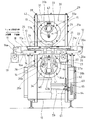
図1および図2は、本発明の実施例に係る横型製袋充填機におけるエンドシール装置の全体構成を示すものであって、四角枠状に形成された機枠10におけるフィルム移送方向の上流側に、第1移送コンベヤ(移送コンベヤ)11が配設されると共に、その下流側に、第1移送コンベヤ11と移送レベルを一致させた第2移送コンベヤ(移送コンベヤ)12が直列に配設されている。そして、両コンベヤ11,12の対向する端部間に、フィルム移送方向に移動すると共に、上下方向に互いに近接・離間移動(開閉作動)する上側の第1シール部材(シール部材)13と下側の第2シール部材(シール部材)14とを備えたエンドシール装置15が配設される。
【0010】
前記エンドシール装置15の説明に先立ち、前記第1移送コンベヤ11および第2移送コンベヤ12の構成につき、簡単に説明する。エンドシール装置15の配設位置より上流側の機枠10の上部に、前後方向に所定間隔離間する一対の側板からなる第1固定フレーム16が配設される。また第1固定フレーム16の内側には、前記側板の離間間隔よりも小さい間隔で前後方向に離間して対向する一対の側板および上板から下方に開放するコ字状に形成された第1移動フレーム17が、第1固定フレーム16に対してフィルム移送方向への水平移動が可能に配設されている。更に、第1固定フレーム16に複数のプーリ16aが回動可能に枢支されると共に、第1移動フレーム17にも複数のプーリ17aが回動可能に枢支され、これらプーリ16a,17a間に第1無端ベルト18が走行可能に巻掛けられて第1移送コンベヤ11が構成される。前記第1固定フレーム16に配設されている所定位置のプーリ16aには、該フレーム16の下部に配設した第1モータ19が接続され、該モータ19によりプーリ16aを所要方向に回転することによって第1無端ベルト18が所要方向に走行するようになっている。
【0011】
前記第2移送コンベヤ12は、エンドシール装置15を挟んで前記第1移送コンベヤ11と略対称に構成されている。すなわち、機枠10の上部に、前後方向に所定間隔離間する一対の側板から構成される第2固定フレーム20が配設される。また第2固定フレーム20の内側に、前記側板の離間間隔よりも小さい間隔で前後方向に離間して対向する一対の側板および上板から下方に開放するコ字状に形成された第2移動フレーム21が、第2固定フレーム20に対してフィルム移送方向への水平移動が可能に配設されている。更に、第2固定フレーム20に複数のプーリ20aが回動可能に枢支されると共に、第2移動フレーム21にも複数のプーリ21aが回動可能に枢支され、これらプーリ20a,21a間に第2無端ベルト22が走行可能に巻掛けられて第2移送コンベヤ12が構成される。前記第2固定フレーム20に配設されている所定位置のプーリ20aには、該フレーム20の下部に配設した第2モータ23が接続され、該モータ23によりプーリ20aを所要方向に回転することによって第2無端ベルト22が所要方向に走行するようになっている。
【0012】
前記第1移送コンベヤ11では、第1無端ベルト18がフィルム移送速度と略同速で所要方向に走行されるよう設定されており、該無端ベルト18に載置された物品24が充填された筒状フィルム25は、エンドシール装置15に向けて移送される。また第2移送コンベヤ12では、第2無端ベルト22が第1無端ベルト18の走行速度よりも高速となるよう設定されており、エンドシール装置15の両シール部材13,14によりエンドシール・切断された先行の包装体を、後続の未包装体から確実に切離して排出し得るよう構成されている。
【0013】
また図1に示すように、前記第1移動フレーム17の下流端部に垂設した第1カム板26に、下方から上方に向けて第2移動フレーム側に近接する第1カム溝26aが形成されると共に、前記第2移動フレーム21の上流端部に垂設した第2カム板27に、下方から上方に向けて第1移動フレーム側に近接する第2カム溝27aが形成されている。そして、前記第2シール部材14を水平に支持する保持部材41(後述)に配設された上流側の第1ローラ28aが第1カム溝26aに摺動自在に嵌合し、下流側の第2ローラ28bが第2カム溝27aに摺動自在に嵌合されている。すなわち、第1移動フレーム17および第2移動フレーム21の前記シール部材13,14を指向するコンベヤ先端は、前記シール部材13,14のフィルム移送方向の動作と対応してフィルム移送方向へ移動し、第1移動フレーム17の先端は、前記シール部材13,14の上流側に、また第2移動フレーム21の先端は、前記シール部材13,14の下流側に常に位置するよう構成される。更に、第2シール部材14が最下点に位置した状態では、第1移動フレーム17と第2移動フレーム21とは相互に近接し、第2シール部材14の上昇移動と共に両ローラ28a,28bが上昇すると、第1移動フレーム17と第2移動フレーム21とは相互に離間して、前記シール部材13,14を指向するコンベヤ先端間に第2シール部材14のコンベヤ上方への移動を許容する隙間を形成するよう構成されている。なお、前記第1カム板26および第2カム板27は、対応する移動フレーム17,21における後側の側板にのみ配設され、両カム板26,27およびローラ28a,28bからなり、両移動フレーム17,21の先端を両シール部材13,14のフィルム移送方向の動作と対応して移動させると共に相対的に近接・離間移動させる開閉手段が、フィルム移送路の前側に臨まないようにしてある。
【0014】
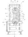
次に、前記エンドシール装置15の構成につき説明する。前記第1移送コンベヤ11および第2移送コンベヤ12の配設位置に対して後側(図2の右側)に臨む機枠10に、枠状に形成された支持フレーム29が配設され、該支持フレーム29に枠体30が上下方向に移動可能に取付けられている。この枠体30は、図3に示す如く、前後方向に離間するよう対向して配設した一対の枠部材31,32から構成され、両枠部材31,32間には、その上方位置に第1回転体対33が配設されると共に、下方位置に第2回転体対34が配設される。第1回転体対33は、前側に臨む前枠部材31に回転可能に支持された前第1回転体(第1回転体)33aと、後側に臨む後枠部材32に回転可能に支持された後第1回転体(第1回転体)33bとからなり、両者33a,33bの回転軸心は水平に整列し、第1回転体対33における回転軸心の方向が前後方向に一致するよう設定されている。また、両回転体33a,33bの回転軸心から偏心した位置には、第1筒状体35が共通的に連結されて一体回転可能に構成される。また第2回転体対34は、第1回転体対33と同様に、前側に臨む前枠部材31に回転可能に支持された前第2回転体(第2回転体)34aと、後側に臨む後枠部材32に回転可能に支持された後第2回転体(第2回転体)34bとからなり、両者34a,34bの回転軸心は水平に整列し、第2回転体対34における回転軸心の方向が前後方向に一致するよう設定されると共に、両回転体34a,34bの回転軸心から偏心した位置に第2筒状体36が共通的に連結されて一体回転可能に構成されている。なお、第1回転体対33の回転軸心と第2回転体対34の回転軸心とは同一鉛直面上にあって平行となるよう設定される。更に、前記後第1回転体33bにおける後枠部材32から後側外方に突出する端部に第1従動歯車37が一体回転可能に配設されると共に、前記後第2回転体34bにおける後枠部材32から後側外方に突出する端部に第2従動歯車38が一体回転可能に配設してある。
【0015】
図3に示す如く、前記第1回転体対33における第1筒状体35には、前記第1シール部材13が配設される第1支持部材39の円柱状の軸部39aが前側から挿通されて回動可能に支持されるようになっている。この軸部39aの前側の端部に連設されて、第1筒状体35から回転軸心方向に沿って前側外方に延出して筒状フィルム25の移送路上方に臨む一方の突出部分としての角柱状の支持部39bの下面に、第1シール部材13が、そのシール面を筒状フィルム25の移送路を指向する下向き状態で配設される。また、前記第2回転体対34における第2筒状体36には、前記第2シール部材14が配設される第2支持部材40の円柱状の軸部40aが前側から挿通されて回動可能に支持される。この軸部40aの前側の端部に連設されて、第2筒状体36から回転軸心方向に沿って前側外方に延出して筒状フィルム25の移送路下方に延出する一方の突出部分としての角柱状の支持部40bの上面に、前記第1シール部材13とフィルム移送路を挟んで平行に対向する第2シール部材14が、保持部材41を介してそのシール面をフィルム移送路に指向させた上向き状態で配設される。各支持部材39,40の対応する回転体対33,34に対する回動軸心は、該回転体対33,34の枠部材31,32に対する回転軸心と平行で、該回動軸心の該回転軸心からの偏心量は、第1回転体対33と第2回転体対34とにおいて同一に設定されている。そして、前記一対の回転体対33,34を互いに反対向きに回転することにより、一対のシール部材13,14は、後述する姿勢保持機構53によりシール面を対向した姿勢を保ったまま互いに反対向きに同一回転半径で円運動されるようになっている。なお、前記一対のシール部材13,14の円運動軌跡は、所定区間において重なるよう設定され、この重合区間において両シール部材13,14が前記筒状フィルム25を挟んで当接した状態で下流側に向けて移動する際に、該フィルム25に所定圧力のもとでエンドシールを施すよう構成される。
【0016】
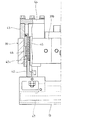
前記第1シール部材(一方のシール部材)13は、第1支持部材39の支持部39bに対して、前後方向に離間する一対のスライド支持手段としての支持軸42,42を介して、第2シール部材(他方のシール部材)14との対向方向である上下方向に移動可能に配設される。各支持軸42は、図4に示す如く、その下端が第1シール部材13にネジ止め固定されると共に、上部側が支持部39bに配設された案内筒43に摺動可能で、かつ下方への抜け止めがなされた状態で挿通されている。また案内筒43の上部を覆うように配設された蓋部材44の下面略中央に、支持軸42に穿設した収納穴42aに挿通されたガイドロッド45が垂設されると共に、該収納穴42aに内挿された弾性部材としての圧縮コイルバネ46の上端部がガイドロッド45の段部で規制されて、第1シール部材13を常には下向きに(第2シール部材14に向けて)付勢するよう構成されている。そしてこの圧縮コイルバネ46,46は、第1シール部材13と第2シール部材14とが当接した際に、該第1シール部材13の第1支持部材39側への退避を許容すると共に、第2シール部材14との間での所定の挟圧力を得るよう機能する。また、第1シール部材13にはカッタ47が配設され、第2シール部材14との当接時に筒状フィルム25の切断を行なうようになっている。
【0017】
図5に示す如く、前記第1支持部材39における軸部39aの後第1回転体33bから後側外方に突出する他方の突出部分としての端部39cに上連結部材48が前記第1回転体対33に対して第1支持部材39と一体的に回動可能に配設されると共に、該上連結部材48には、フィルム移送方向に離間して一対のスライド軸(軸)49,49の上端部が配設されている。両スライド軸49,49は、下方に向けて所定長さで平行に延在し、その下端部は下連結部材50により連結してある。また、前記第2支持部材40における軸部40aの後第2回転体34bから後側外方に突出する他方の突出部分としての端部40cに軸受ホルダ51が前記第2回転体対34に対して第2支持部材40と一体的に回動可能に配設されると共に、該軸受ホルダ51には、フィルム移送方向に離間して一対のスライド軸受(軸受)52,52が配設され、各スライド軸受52に対応するスライド軸49がスライド可能に挿通されている。そして、これらスライド軸49,49およびスライド軸受52,52から、前記第1および第2シール部材13,14を、円運動に際して一定の姿勢を保ったまま相互に近接・離間移動させるための姿勢保持機構53が構成される。
【0018】
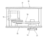
前記後枠部材32における後第1回転体33bと後第2回転体34bとの配設位置の間に、作動軸54が内外方向に延出するように回動可能に軸支されている。また両枠部材31,32の間には、図6に示す如く、後枠部材32に配設された駆動用モータとしてのサーボモータ55が臨んでおり、該モータ55と作動軸54とが、プーリーやベルト等からなる伝達手段56により連繋されている。前記作動軸54の後側外方に延出する軸端部に駆動歯車57が一体回転可能に配設され、該駆動歯車57が後第1回転体33bに配設した前記第1従動歯車37と噛合している。更に、後枠部材32には駆動歯車57と噛合する遊転歯車58が回動可能に枢支されており、該遊転歯車58が後第2回転体34bに配設した前記第2従動歯車38に噛合している。すなわち、サーボモータ55を駆動して作動軸54を所定方向へ回転させると、駆動歯車57、遊転歯車58および一対の従動歯車37,38を介して上下の回転体対33,34は相互に反対向きに回転し、第1回転体対33に配設されている第1支持部材39および第2回転体対34に配設されている第2支持部材40には互いに反対向きの円運動(近接・離間移動)が付与される。そして、前記姿勢保持機構53による第1および第2支持部材39,40の連結構造により、第1シール部材13と第2シール部材14とは、そのシール面を筒状フィルム25の移送路を指向する姿勢を保った状態でフィルム移送方向上流側で相互に近接すると共に下流側で相互に離間する運動を繰返すようになっている。
【0019】
なお、前記シール部材13,14の重合区間における当接状態でのフィルム移送向きへの移動速度は、フィルム移送速度と略同一となるよう設定される。また、上下両回転体対33,34(第1回転体33a,33bと第2回転体34a,34b)の配設間隔を可及的に大きく設定し、両支持部材39,40が最接近した際にも両支持部材39,40の間隔を充分に確保することで、前記姿勢保持機構53に起因する回転体対33,34に対する支持部材39,40の軸部39a,40a(筒状体35,36)回りの回動振れを抑制して、両シール部材13,14の当接状態が良好となるようにしてある。
【0020】
前記支持フレーム29の下端部には、フィルム移送方向に延在する調節軸59が回動可能に枢支されると共に、該調節軸59には軸方向に離間して一対の第1ハスバ歯車60,60(一方のみ図示)が一体回転可能に配設される。また支持フレーム29のフィルム移送方向の両端部に、各第1ハスバ歯車60と噛合する第2ハスバ歯車61が回動可能に枢支されると共に、該第2ハスバ歯車61には上下方向に延在する調節ネジ62が一体的に回転するよう配設され、該調節ネジ62が前記枠体30の対応位置に設けた雌ネジ部材63に螺挿されている。前記調節軸59の一端に調節用操作ハンドル64が配設されており、該ハンドル64を正逆方向に回転することで、調節ネジ62と雌ネジ部材63とからなる調節ネジ手段による螺合作用下に枠体30は支持フレーム29に対して上下方向に移動する。これにより、前記移送コンベヤ11,12で移送される物品24の高さに応じて、前記一対のシール部材13,14が当接する高さ位置の調節を行ない得るようになっている。なお、調節軸59、ハスバ歯車60,61、調節ネジ62および雌ネジ部材63により高さ調節手段65が構成される。
【0021】
【実施例の作用】
次に、実施例に係るエンドシール装置の作用につき説明する。前記第1移送コンベヤ11の第1移動フレーム17および第2移送コンベヤ12の第2移動フレーム21のエンドシール装置15を指向する夫々の先端が相互に近接すると共に、該エンドシール装置15では、前記第1支持部材39と第2支持部材40とが相互に離間した状態で待機し、第1シール部材13と第2シール部材14との間を筒状フィルム25が通過するのを許容する状態となっているものとする(図1参照)。
【0022】
前記第1移送コンベヤ11に移送された物品24が充填された筒状フィルム25は、フィルム移送速度と略同速で走行する第1無端ベルト18により下流側に移送される。エンドシール装置15は、前記サーボモータ55により前述した歯車機構が所要のタイミングで駆動され、前記上下の支持部材39,40が円(回転)運動されることで、前記第1シール部材13と第2シール部材14とは、上流側へ移動しつつ相互に近接する。すなわち、サーボモータ55によって所定方向へ回転する駆動歯車57に噛合する第1従動歯車37により、前記第1回転体対33が回転すると共に、前記遊転歯車58に噛合する第2従動歯車38を介して第2回転体対34は第1回転体対33と逆方向へ回転する。このとき、第1回転体対33に支持されている第1支持部材39および第2回転体対34に支持されている第2支持部材40は、前記姿勢保持機構53のスライド軸49,49とスライド軸受52,52とがスライドすることで、夫々姿勢を保ったまま上流側下方および上方へ円運動し、これと一体的に第1シール部材13および第2シール部材14も夫々上流側下方および上方へ姿勢を保ったまま円運動する。また、前記第1および第2の移送コンベヤ11,12の各移動フレーム17,21の先端は、両シール部材13,14のフィルム移送方向の動作と対応してフィルム移送方向へ移動する。
【0023】
前記一対のシール部材13,14が下流側に移動しつつ相互に近接することで、両シール部材13,14が、筒状フィルム25内のフィルム移送方向に隣り合う物品間に位置する筒状フィルム25を挟んで当接するに至る。このとき、前記第2シール部材14の移動に連動して、前記第1および第2移送コンベヤ11,12の各移動フレーム17,21の先端が相互に離間移動し、第2シール部材14の上方への突出を許容する隙間を画成する。
【0024】
前記両シール部材13,14は、前記重合区間を移動する間は当接した状態で筒状フィルム25の移送に伴って略同一速度で下流側に移動し、これにより該フィルム25に確実なエンドシールが施される。なお、前記重合区間において第1シール部材13は圧縮コイルバネ46,46の弾力に抗して第1支持部材39側に退避すると共に、該バネ46,46の弾力によって第2シール部材14に圧接された状態で移動する。また、両シール部材13,14が当接している状態で前記カッタ47が作動して筒状フィルム25が切断される。前記各圧縮コイルバネ46は、図4に示すように、前記支持軸42に内挿されると共に案内筒43や蓋部材44により外部に露出しないよう構成してあるから、該バネ46のコイル間にゴミ等が溜まらず、圧縮コイルバネ46に対する清掃等のメンテナンスは不要となる。
【0025】
前記両回転体対33,34が更に所定方向へ回転する結果として、前記姿勢保持機構53の作用により両シール部材13,14は姿勢を保ったまま筒状フィルム25から相互に離間して該フィルム25を解放する。そして、両シール部材13,14によりエンドシール・切断がなされることで得られた包装体は、高速で運転されている第2移送コンベヤ12によりエンドシール装置15の配設位置から速やかに下流側に移送される。また第2シール部材14の下降に連動して、各移動フレーム17,21が相互に近接するので、次の物品24の第1移送コンベヤ11から第2移送コンベヤ12への受渡しは円滑になされる。
【0026】
前述したように、前記回転体対33,34、該回転体対33,34(シール部材13,14)を回転駆動するための伝達手段56、各歯車37,38,57,58等の回転伝達部材およびシール部材13,14の姿勢を保持する姿勢保持機構53は、シール部材13,14、すなわちフィルム移送路の側方に配設されているから、これら回転体対33,34、伝達手段56、回転伝達部材および姿勢保持機構53に空袋や物品24のカス等の異物が巻き込まれることはなく、これらの回転部分やスライド部分に対する清掃等のメンテナンスは不要となる。また、シール部材13,14が配設された支持部材39,40は、後側のみが回転体対33,34および枠体30に片持式に支持されて、前側、すなわちオペレータが位置する側は開放状態となっているので、空袋や物品24のカス等が前記移送コンベヤ11,12の付近に散乱したり、物品24のカス等が無端ベルト18,22に付着しても早期に発見することができ、またこれに対応した清掃等のメンテナンスを容易に行なうことが可能となる。更に、シール部材13,14にフィルムの溶融したカス等が付着した場合等も、同様にシール部材13,14に対する清掃は容易である。
【0027】
次に、オーダ変更等によって物品24の高さ寸法が変わった場合は、前記調節用操作ハンドル64を所定方向に回転することで、調節ネジ62と雌ネジ部材63との螺合作用下に前記枠体30が支持フレーム29に対して上下方向にスライド調節され、両シール部材13,14の当接位置を、物品24の高さ方向の中間位置にすることができる。これにより、物品24に対するフィルムのエンドシール位置を常に高さ方向の中間とすることが可能となる。なお、前記回転体対33,34を回転駆動するサーボモータ55は、図6に示すように、枠体30の内部に配設されて高さ調節手段65により一体的に移動調節されるよう構成してあるから、駆動力の伝達系が複雑とならず、装置のコンパクト化が達成される。
【0028】
【変更例】
前記回転体対に関しては、一対の回転体を筒状体で連結する構成に代えて、適宜の連結部材で前側および後側の両回転体を一体的に回転可能に連結すると共に、各回転体に設けた回転軸受により両回転体で支持部材を回動可能に支持する構成を採用し得る。また、シール部材の姿勢保持機構については、下側の第2支持部材にスライド軸を配設し、上側の第1支持部材にスライド軸受を配設してもよい。更に、姿勢保持機構におけるスライド軸およびスライド軸受は、各一つずつでもよく、この場合にスライド軸やスライド軸受を支持部材に直接設けることも可能である。
【0029】
前記シール部材の当接する高さ位置を調節する高さ調節手段は、手動で操作するのに代えて、駆動モータ等により自動で位置調節する構成を採用し得る。また一対の移送コンベヤの先端を近接・離間移動する開閉手段に関しては、実施例とは逆でカム板を第2シール部材側に配設すると共にローラをコンベヤ側に配設したり、あるいはリンク杆等でコンベヤと第2シール部材とを連結する構成とすることができる。更に、実施例では圧縮コイルバネ(弾性部材)を支持軸に内挿したが、該バネが内挿されるスライド支持手段としては、支持部材側に配設される案内筒等、その他の部材であってもよい。
【0030】
【発明の効果】
以上に説明した如く、本願の請求項1の発明に係る横型製袋充填機におけるエンドシール装置によれば、フィルム移送路の側方に配設された一対の枠部材に支持された第1 , 第2回転体対に片持ち状態で支持されている支持部材の支持部にシール部材を配設したから、該シール部材におけるフィルム移送路の手前側は開放しており、シール部材や支持部材に対する清掃等のメンテナンスを容易に行なうことができる。また、支持部材における後枠部材の外側方への突出部に、第1 , 第2回転体対を互いに反対向きに回転駆動するための回転伝達部材およびシール部材の姿勢を保持するためのスライド軸や軸受を設けたから、これらもフィルム移送路の後側に位置し、空袋や物品のカス等の異物を巻き込むおそれはなく、清掃等のメンテナンスを不要とし得る。
【0031】
また請求項2に係る発明では、一対のシール部材が当接する高さ位置を調節する高さ調節手段を設けたので、物品の高さに合わせてシール部材の当接高さ位置を変更調節できる。従って、筒状フィルムに対し、皺のない良好なエンドシールを施し得る。更に、請求項3に係る発明では、シール部材の配設位置のフィルム移送方向上流側および下流側に配設した移送コンベヤを、一対のシール部材の近接・離間移動に伴い離間・近接移動するよう構成したので、エンドシール装置の配設位置を通過する物品の確実な受渡しを達成し得る。また、シール部材におけるフィルム移送路の手前側は開放状態となっているから、移送コンベヤに対する清掃等のメンテナンスを容易に行なうことができる。
【図面の簡単な説明】
【図1】本発明の実施例に係るエンドシール装置を一部断面で示す概略正面図である。
【図2】実施例に係るエンドシール装置を一部断面で示す概略側面図である。
【図3】実施例に係る支持部材の回転体対に対する配設部位を示す要部縦断側面図である。
【図4】実施例に係る第1支持部材に対する第1シール部材の配設部位を示す要部縦断側面図である。
【図5】実施例に係るエンドシール装置を一部破断して示す背面図である。
【図6】実施例に係る枠体を示す横断平面図である。
【符号の説明】
11 第1移送コンベヤ(移送コンベヤ)
12 第2移送コンベヤ(移送コンベヤ)
13 第1シール部材(シール部材)
14 第2シール部材(シール部材)
24 物品
25 筒状フィルム
26 第1カム板(開閉手段)
27 第2カム板(開閉手段)
28a 第1ローラ(開閉手段)
28b 第2ローラ(開閉手段)
31 前枠部材
32 後枠部材
33 第1回転体対
33a 前第1回転体(第1回転体)
33b 後第1回転体(第1回転体)
34 第2回転体対
34a 前第2回転体(第2回転体)
34b 後第2回転体(第2回転体)
37 第1従動歯車 ( 回転伝達部材 )
38 第2従動歯車 ( 回転伝達部材 )
39 第1支持部材(支持部材)
39b 支持部
39c 端部( 突出部 )
40 第2支持部材(支持部材)
40b 支持部
40c 端部( 突出部 )
49 スライド軸
52 スライド軸受(軸受)
57 駆動歯車 ( 回転伝達部材 )
58 遊転歯車 ( 回転伝達部材 )
65 高さ調節手段[0001]
BACKGROUND OF THE INVENTION
The present invention relates to an end seal device in a horizontal type bag making and filling machine, and more specifically, a cylindrical film by a pair of sealing members that move in the direction of transfer along with the transfer of the cylindrical film while facing and moving away from each other. The present invention relates to an end seal device that performs end seal by clamping from both sides.
[0002]
[Prior art]
The horizontal bag making and filling machine sequentially supplies articles into a film that is horizontally transferred while being formed from a strip shape into a cylindrical shape by a bag making machine, and performs a center seal on the overlapping surface of the side edges of the film, A so-called pillow package can be manufactured by performing end sealing and cutting between adjacent articles in a cylindrical film.
[0003]
An end seal device for end sealing and cutting disposed in the horizontal bag making and filling machine is opposed to both sides sandwiching the transfer path of the tubular film as disclosed in, for example, Japanese Patent Laid-Open No. 7-267203. Two seal sets in which a seal member is arranged between a pair of support plates are arranged so that each seal member faces up and down across the transfer path, and the two seal members are kept facing each other. A configuration is adopted in which the circular motion is performed as it is. And in the state which clamped the cylindrical film by making both sealing members contact, both the sealing members are moved synchronously along the transfer direction of the cylindrical film, and end sealing is performed and the film is cut. After that, they are configured to perform so-called box motion, in which they move backward and away from each other, and repeat the motion of moving in contact with each other again.
[0004]
[Problems to be solved by the invention]
In the horizontal bag making and filling machine, a transfer mechanism such as a belt conveyor is provided on the upstream side and the downstream side in the film transfer direction of the end seal device to transfer articles and a tubular film to the seal device, The cylindrical film (packaging body) cut by the end seal is carried out. Further, the horizontal bag making and filling machine is configured such that an operator is located on one side of the film transfer path and performs its operation and maintenance. However, in the above-described end seal device, it is pointed out that maintenance such as cleaning for the end seal device including the transfer mechanism is difficult to perform because there is one of the pair of support plates on the side where the operator is located.
[0005]
OBJECT OF THE INVENTION
In view of the above-mentioned problems inherent in the end seal device according to the prior art, the present invention has been proposed to suitably solve this problem, and in a horizontal bag making and filling machine that can make maintenance easy or unnecessary. An object is to provide an end seal device.
[0006]
[Means for Solving the Problems]
In order to overcome the above problems and achieve the intended purpose, the present invention provides:
A pair of sealing members disposed opposite to each other across the transfer path of the cylindrical film filled with the article, and moved in the transfer direction along with the transfer of the cylindrical film, and opposed to and separated from each other. In an end seal device in a horizontal bag making and filling machine that applies an end seal between adjacent articles in a film,
Before and after the cylindrical film is disposed on the side of the transfer path and directed toward the transfer pathApartThe rotation axis is aligned with each of the front frame member and the rear frame member arranged opposite to each otherIt is supported so that it can rotate integrally.TheFrom a pair of first rotating bodiesRuA first rotating body pair;
SaidIn each frame memberBelow the first rotating body pairAtAt regular intervalsSo that the axis of rotation matchesIt is supported so that it can rotate integrally.TheFrom a pair of second rotating bodiesFirstA pair of rotating bodies,
Each rotating body pairEach inPosition eccentric from the axis of rotationTimesMoveableCantileverSupported,Provided with a support portion extending horizontally to face the transfer pathA pair of support members;
A seal member provided with a seal surface facing each of the support portions in each of the support members;
Disposed on the outer side of the rear frame member, and , A rotation transmitting member for rotating the second rotating body pair in opposite directions;
SaideachSupport memberA projecting portion projecting outward from the rear frame member inOne support memberAnd a slide shaft that is slidably inserted into the bearing, and is arranged to rotate integrally with the protrusion of the other support member. The first , The seal member is configured to be close to and away from each other as the second rotating body pair rotates.It is characterized by that.
[0008]
DETAILED DESCRIPTION OF THE INVENTION
Next, the end seal device in the horizontal bag making and filling machine according to the present invention will be described with reference to the accompanying drawings by giving a preferred embodiment. In addition, in an Example, the direction orthogonal to the horizontal transfer direction of a cylindrical film is called a front-back direction, and an operator shall be located in the front side with respect to the transfer path of a cylindrical film.
[0009]
1 and 2 show the overall configuration of an end seal device in a horizontal bag making and filling machine according to an embodiment of the present invention, and the upstream side in the film transport direction in a
[0010]
Prior to the description of the
[0011]
The
[0012]
In the
[0013]
Further, as shown in FIG. 1, a
[0014]
Next, the configuration of the
[0015]
As shown in FIG. 3, a
[0016]
The first seal member (one seal member) 13 is connected to a
[0017]
As shown in FIG. 5, the upper connecting
[0018]
An operating
[0019]
In addition, the moving speed in the film transfer direction in the contact state in the overlapping section of the
[0020]
An
[0021]
[Effect of the embodiment]
Next, the operation of the end seal device according to the embodiment will be described. The front ends of the first moving
[0022]
The
[0023]
The pair of
[0024]
Both the sealing
[0025]
As a result of the rotation of the rotary member pairs 33 and 34 in a predetermined direction, the
[0026]
As described above, the rotation transmission of the
[0027]
Next, when the height dimension of the
[0028]
[Example of change]
With respect to the pair of rotating bodies, instead of the configuration in which the pair of rotating bodies are connected by a cylindrical body, both the front and rear rotating bodies are connected together by an appropriate connecting member so as to be integrally rotatable. It is possible to adopt a configuration in which the support member is rotatably supported by both rotary bodies by a rotary bearing provided in the base. As for the posture holding mechanism of the seal member, a slide shaft may be provided on the lower second support member, and a slide bearing may be provided on the upper first support member. Further, one slide shaft and one slide bearing in the posture holding mechanism may be provided, and in this case, the slide shaft and the slide bearing may be directly provided on the support member.
[0029]
The height adjusting means for adjusting the height position where the seal member abuts may employ a configuration in which the position is automatically adjusted by a drive motor or the like instead of being manually operated. As for the opening / closing means for moving the front and rear of the pair of transfer conveyors closer to and away from each other, the cam plate is disposed on the second seal member side and the roller is disposed on the conveyor side, or the link rod, contrary to the embodiment. For example, the conveyor and the second seal member may be connected. Further, in the embodiment, the compression coil spring (elastic member) is inserted into the support shaft, but the slide support means into which the spring is inserted is another member such as a guide tube disposed on the support member side. Also good.
[0030]
【The invention's effect】
As explained above, according to the end seal device in the horizontal bag making and filling machine according to the invention of claim 1 of the present application,The first supported by a pair of frame members disposed on the sides of the film transfer path , SecondRotating body pairIn a cantilevered stateSupported support memberOn the support partSince the seal member is disposed, the film transfer path of the seal memberhandThe front side is open, and maintenance such as cleaning of the seal member and the support member can be easily performed. Also,Support memberTo the outside of the rear frame memberProtrusionPart,First , A slide for maintaining the posture of the rotation transmitting member and the seal member for rotationally driving the second rotating body pair in opposite directions.axisAndSince bearings are provided, these are alsoRear sideTherefore, there is no possibility that foreign matter such as empty bags or scum of articles will be caught, and maintenance such as cleaning may be unnecessary.
[0031]
In the invention according to claim 2, since the height adjusting means for adjusting the height position at which the pair of seal members contact is provided, the contact height position of the seal member can be changed and adjusted according to the height of the article. . Therefore, a good end seal without wrinkles can be applied to the tubular film. Furthermore, in the invention according to claim 3, the transfer conveyor disposed on the upstream side and the downstream side in the film transport direction at the position where the seal member is disposed is separated and moved in close proximity with the proximity and separation of the pair of seal members. Since it comprised, the reliable delivery of the articles | goods which pass the arrangement | positioning position of an end seal apparatus can be achieved. Also, the film transfer path of the seal memberFront sideSince it is in an open state, maintenance such as cleaning of the transfer conveyor can be easily performed.
[Brief description of the drawings]
FIG. 1 is a schematic front view showing a partial cross section of an end seal device according to an embodiment of the present invention.
FIG. 2 is a schematic side view showing the end seal device according to the embodiment in a partial cross section.
FIG. 3 is a longitudinal sectional side view of a main part showing an arrangement site of a support member according to an embodiment with respect to a rotating body pair.
FIG. 4 is a longitudinal sectional side view of a main part showing an arrangement site of a first seal member with respect to a first support member according to an embodiment.
FIG. 5 is a rear view showing the end seal device according to the embodiment in a partially broken view.
FIG. 6 is a cross-sectional plan view showing a frame according to the embodiment.
[Explanation of symbols]
11 First transfer conveyor (transfer conveyor)
12 Second transfer conveyor (transfer conveyor)
13 First seal member (seal member)
14 Second seal member (seal member)
24 goods
25 Cylindrical film
26 First cam plate (opening / closing means)
27 Second cam plate (opening / closing means)
28a First roller (opening / closing means)
28b Second roller (opening / closing means)
31 Front frame member
32 Rear frame member
33 First rotating body pair
33a Front first rotating body (first rotating body)
33b Rear first rotating body (first rotating body)
34 Second rotating body pair
34a Front second rotating body (second rotating body)
34b Rear second rotating body (second rotating body)
37 1st driven gear ( Rotation transmission member )
38 Second driven gear ( Rotation transmission member )
39 First support member (support member)
39b supportPart
39c end( SuddenOutPart )
40 Second support member (support member)
40b supportPart
40c end( SuddenOutPart )
49 slidesaxis
52 Slide bearing (bearing)
57 Drive gear ( Rotation transmission member )
58 idle gear ( Rotation transmission member )
65 Height adjustment means
Claims (3)
前記筒状フィルム (25) の移送路の側方に配設され、該移送路に向けた前後に離間して対向配置した前枠部材 (31) と後枠部材 (32) の夫々に回転軸心が一致するよう一体回転可能に支持された一対の第1回転体(33a,33b)からなる第1回転体対(33)と、
前記各枠部材 (31,32) において第1回転体対(33)の下方に所定間隔離間して回転軸心が一致するよう一体回転可能に支持された一対の第2回転体(34a,34b)からなる第2回転体対(34)と、
前記各回転体対(33,34)における夫々の回転軸心から偏心した位置に回動可能に片持支持され、前記移送路に臨むよう水平に延出する支持部 (39b,40b) を備えた一対の支持部材(39,40)と、
前記各支持部材 (39,40) における支持部 (39a,40a) の夫々に、シール面を対向して配設したシール部材 (13,14) と、
前記後枠部材 (32) の外側方に配設され、前記第1 , 第2回転体対 (33,34) を互いに反対向きに回転駆動する回転伝達部材 (37,38,57,58) と、
前記各支持部材(39,40)における前記後枠部材 (32) より外側方に突出する突出部 (39c,40c) と、一方の支持部材(40)の突出部 (40c) に一体回動するよう配設した軸受 (52) と、他方の支持部材 (40) の突出部 (39c) に一体回動するよう配設すると共に、前記軸受 (52) にスライド可能に挿通されるスライド軸 (49) との夫々を有し、前記第1 , 第2回転体対 (33,34) の回転に伴い前記シール部材 (13,14) を相互に近接・離間し得るよう構成した
ことを特徴とする横型製袋充填機におけるエンドシール装置。Located opposite to each other across the transfer path of the tubular film (25) filled with the article (24), while moving in the transfer direction along with the transfer of the tubular film (25), facing and separating from each other In the end seal device in the horizontal bag making and filling machine that performs end seal between adjacent articles in the tubular film (25) by the pair of moving seal members (13, 14),
A rotating shaft is disposed on each of the front frame member (31) and the rear frame member (32) disposed on the side of the transfer path of the tubular film (25) and arranged opposite to each other in the front- rear direction toward the transfer path. a pair of first rotating member which is integrally rotatably supported to the mind matches (33a, 33b) the first rotor pair Ru Tona (33),
Wherein each frame member (31, 32) in the first pair of rotating members (33) a pair of second rotating member which is integrally rotatably supported to be spaced Jo Tokoro distance below the axis of rotation is coincident in (34a, 34b) second rotator pair Ru Tona (34),
Wherein each pair of rotating members (33, 34) in the eccentric position twice rotatably in cantilevered from each of the rotation axis, comprises a supporting portion extending horizontally to face the transport path (39 b, 40b) A pair of support members (39, 40),
Each of the support portions (39a, 40a ) in each of the support members (39 , 40) , a seal member (13, 14) disposed with a seal surface facing each other ,
A rotation transmitting member (37, 38, 57, 58) disposed on the outer side of the rear frame member (32) and configured to rotate the first and second rotating body pairs (33, 34) in opposite directions ; ,
Wherein a protrusion protruding from the outer side the rear frame member (32) in the support members (39, 40) (39c, 40c), is integrally rotated in the projecting portion of (40c) one of the support member (40) The bearing (52) arranged in this manner and the slide shaft (49 ) which is arranged to rotate integrally with the protrusion (39c) of the other support member (40) and is slidably inserted into the bearing (52). ) and has a respective, the first 1, <br/> that the sealing member along with the rotation of the second rotor pair (33, 34) (13, 14) configured to be close to and away from each other An end seal device for a horizontal bag making and filling machine.
Priority Applications (1)
| Application Number | Priority Date | Filing Date | Title |
|---|---|---|---|
| JP2001218762A JP3780452B2 (en) | 2001-07-18 | 2001-07-18 | End seal device for horizontal bag making and filling machine |
Applications Claiming Priority (1)
| Application Number | Priority Date | Filing Date | Title |
|---|---|---|---|
| JP2001218762A JP3780452B2 (en) | 2001-07-18 | 2001-07-18 | End seal device for horizontal bag making and filling machine |
Publications (3)
| Publication Number | Publication Date |
|---|---|
| JP2003026125A JP2003026125A (en) | 2003-01-29 |
| JP2003026125A5 JP2003026125A5 (en) | 2004-08-19 |
| JP3780452B2 true JP3780452B2 (en) | 2006-05-31 |
Family
ID=19052889
Family Applications (1)
| Application Number | Title | Priority Date | Filing Date |
|---|---|---|---|
| JP2001218762A Expired - Fee Related JP3780452B2 (en) | 2001-07-18 | 2001-07-18 | End seal device for horizontal bag making and filling machine |
Country Status (1)
| Country | Link |
|---|---|
| JP (1) | JP3780452B2 (en) |
Families Citing this family (3)
| Publication number | Priority date | Publication date | Assignee | Title |
|---|---|---|---|---|
| JP5944656B2 (en) * | 2011-12-07 | 2016-07-05 | 大森機械工業株式会社 | Sealing device |
| CN110182749A (en) * | 2019-06-26 | 2019-08-30 | 惠州市一诺纯美家居用品有限公司 | One kind filling cotton equipment |
| JP7577344B2 (en) | 2022-05-12 | 2024-11-05 | 株式会社フジキカイ | Horizontal sealing device for horizontal bag making and filling machines |
-
2001
- 2001-07-18 JP JP2001218762A patent/JP3780452B2/en not_active Expired - Fee Related
Also Published As
| Publication number | Publication date |
|---|---|
| JP2003026125A (en) | 2003-01-29 |
Similar Documents
| Publication | Publication Date | Title |
|---|---|---|
| JP4662100B2 (en) | Bag transfer device in bagging and packaging machine | |
| US5904027A (en) | Flowpackaging machine with adjustable closing jaws | |
| US4817363A (en) | Fitment inserter machine | |
| CN111103300B (en) | An integrated detection device for foreign matter and leakage of infusion bottles | |
| FR2546850A1 (en) | MACHINE FOR FORMING AND FILLING BAGS | |
| CN101474891A (en) | Technique for folding and producing adsorption type napkin paper and device thereof | |
| JP6158598B2 (en) | Opening device for bag mouth of continuously transferred bags | |
| US6581360B1 (en) | Packaging machinery | |
| JP5038845B2 (en) | End seal device | |
| JP3780452B2 (en) | End seal device for horizontal bag making and filling machine | |
| JP2009083883A (en) | End seal device | |
| JP2001278222A (en) | Horizontal sealing device of horizontal bag-making and filling machine | |
| JP3780450B2 (en) | End seal device for horizontal bag making and filling machine | |
| JP4163036B2 (en) | End seal device for horizontal bag making and filling machine | |
| US5186435A (en) | Apparatus for compressing a spring | |
| CN212373780U (en) | High-speed traditional Chinese medicine decoction pieces packet packaging machine | |
| US4179867A (en) | Packaging machine | |
| JP3947866B2 (en) | End seal device for horizontal bag making and filling machine | |
| JPH02282003A (en) | Belt conveyor for box motion type heat melt cutting sealing device for horizontal bag making filling packaging machine | |
| JP2001206318A (en) | Horizontal sealing apparatus of horizontal bag making and filling machine | |
| JP3353081B2 (en) | Packaging machine film cutting equipment | |
| JP3735477B2 (en) | Packaging machine feeding device for packaging machine | |
| GB2024089A (en) | Machine for forming lollies | |
| CN112046867B (en) | High-speed traditional Chinese medicine decoction piece small package packaging machine | |
| CN212401749U (en) | Sealing machine matched with weighing bagging machine |
Legal Events
| Date | Code | Title | Description |
|---|---|---|---|
| A977 | Report on retrieval |
Free format text: JAPANESE INTERMEDIATE CODE: A971007 Effective date: 20050929 |
|
| A131 | Notification of reasons for refusal |
Free format text: JAPANESE INTERMEDIATE CODE: A131 Effective date: 20051004 |
|
| A521 | Written amendment |
Free format text: JAPANESE INTERMEDIATE CODE: A523 Effective date: 20051202 |
|
| TRDD | Decision of grant or rejection written | ||
| A01 | Written decision to grant a patent or to grant a registration (utility model) |
Free format text: JAPANESE INTERMEDIATE CODE: A01 Effective date: 20060124 |
|
| A61 | First payment of annual fees (during grant procedure) |
Free format text: JAPANESE INTERMEDIATE CODE: A61 Effective date: 20060222 |
|
| R150 | Certificate of patent or registration of utility model |
Ref document number: 3780452 Country of ref document: JP Free format text: JAPANESE INTERMEDIATE CODE: R150 Free format text: JAPANESE INTERMEDIATE CODE: R150 |
|
| FPAY | Renewal fee payment (event date is renewal date of database) |
Free format text: PAYMENT UNTIL: 20090317 Year of fee payment: 3 |
|
| FPAY | Renewal fee payment (event date is renewal date of database) |
Free format text: PAYMENT UNTIL: 20110317 Year of fee payment: 5 |
|
| R250 | Receipt of annual fees |
Free format text: JAPANESE INTERMEDIATE CODE: R250 |
|
| FPAY | Renewal fee payment (event date is renewal date of database) |
Free format text: PAYMENT UNTIL: 20130317 Year of fee payment: 7 |
|
| R250 | Receipt of annual fees |
Free format text: JAPANESE INTERMEDIATE CODE: R250 |
|
| FPAY | Renewal fee payment (event date is renewal date of database) |
Free format text: PAYMENT UNTIL: 20150317 Year of fee payment: 9 |
|
| R250 | Receipt of annual fees |
Free format text: JAPANESE INTERMEDIATE CODE: R250 |
|
| R250 | Receipt of annual fees |
Free format text: JAPANESE INTERMEDIATE CODE: R250 |
|
| R250 | Receipt of annual fees |
Free format text: JAPANESE INTERMEDIATE CODE: R250 |
|
| R250 | Receipt of annual fees |
Free format text: JAPANESE INTERMEDIATE CODE: R250 |
|
| LAPS | Cancellation because of no payment of annual fees |