JP3779708B2 - Manufacturing method of dry barrel polishing container - Google Patents
Manufacturing method of dry barrel polishing container Download PDFInfo
- Publication number
- JP3779708B2 JP3779708B2 JP2003333508A JP2003333508A JP3779708B2 JP 3779708 B2 JP3779708 B2 JP 3779708B2 JP 2003333508 A JP2003333508 A JP 2003333508A JP 2003333508 A JP2003333508 A JP 2003333508A JP 3779708 B2 JP3779708 B2 JP 3779708B2
- Authority
- JP
- Japan
- Prior art keywords
- container
- barrel
- polishing
- polyurethane
- mold
- Prior art date
- Legal status (The legal status is an assumption and is not a legal conclusion. Google has not performed a legal analysis and makes no representation as to the accuracy of the status listed.)
- Expired - Fee Related
Links
Images


Landscapes
- Finish Polishing, Edge Sharpening, And Grinding By Specific Grinding Devices (AREA)
- Moulds For Moulding Plastics Or The Like (AREA)
- Casting Or Compression Moulding Of Plastics Or The Like (AREA)
Description
本発明は、乾式バレル研磨用容器の製造方法に関する。 The present invention relates to a method for manufacturing a dry barrel polishing container.
バレル槽が回転するタイプのバレル研磨装置で使用するバレル槽は、容器とこの容器の開口部を閉鎖する蓋とよりなる。この容器は一般にスチール製の筐体と、その内壁部に弾性材よりなるライニングを施したものとからなり、ライニングは研磨時の研磨石とワークの衝突を和らげたり、スチール壁の磨耗を防ぐ役割をしている。同様に蓋側もスチール製の基部に対し、容器閉鎖面側にはライニングが施してあるものを使用する。このようなバレル槽をバレル研磨装置に装着して目的の研磨加工を行うのである。 A barrel tank used in a barrel polishing apparatus of a type in which the barrel tank rotates includes a container and a lid that closes the opening of the container. This container is generally composed of a steel housing and an inner wall with a lining made of an elastic material. The lining plays a role in reducing the collision between the grinding stone and the workpiece during polishing and preventing the steel wall from being worn. I am doing. Similarly, the lid side is made of steel and the container closing surface side is lining. Such a barrel tank is mounted on a barrel polishing apparatus to perform a desired polishing process.
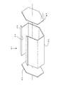
ところでこの容器のスチール製筐体は、図1〜3に示すようにスチール板39を曲げ加工して製作している。例えば図3のように1面に開口部40を有する断面6角形の容器47を製作するには、スチール板39を断面6角形になるように曲げ加工し、その後両端部を6角形状のスチール板42で溶接などにより閉鎖して筐体41とする。次に筐体41に中子44a、44bを開口部40より装入して内部で組み付け、一体の中子44とするとともに筐体41のフランジ45にブリッジ31を架渡し、ブリッジ31を介して中子44を吊下げる。その後溶融ポリウレタン樹脂などのライニング46の基になるものを筐体41内壁と中子44の間に注型する。これを冷却固化するとポリウレタンからなるライニング46を備えたバレル研磨用容器47となる。
By the way, the steel casing of the container is manufactured by bending a
ところで、最近バレル研磨の分野でも環境改善や加工コストの節約面から、従来の水を使用する湿式研磨法から水を使用しない乾式研磨法の需要が増えつつある。乾式研磨に使用するバレル槽は、例えば以下の特許文献1にあるように、容器あるいは蓋の壁面にエアーを導入する外気吸込み部と研磨屑や粉塵を排出する粉塵排出部とを備えている。このようなバレル槽を研磨装置に取り付けて始動すると、バレル槽内では研磨石とワークが相対的に高速移動してワークの研磨が行われる。研磨中、集塵機の作用によって外気吸込み部からはエアーが取り込まれ、研磨石とワークの中を通過してこれらを冷却するとともに、研磨によって生じた研磨屑や粉塵を粉塵排出部を経て集塵機側へ排出するようになっており、乾式研磨固有の問題である研磨屑や粉塵による研磨石の目詰まりや、ワークへの汚れの付着が防止できるようになっている。
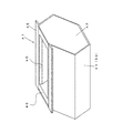
このような乾式研磨用バレル槽を製作するには、前記同様にスチール製筐体41を製作後、ポリウレタンなどのライニング46を注型によって貼着し、その後外気吸込み部や粉塵排出部として研磨石やワークが通過不能な小孔50を孔あけ加工によって複数形成するか(図4a)、筐体41に大きめの通気部51を形成しておき、これより若干大きい通気部52を有するライニング46を注型によって貼着し、その後通気部52に研磨石やワークが通過不能な小孔4を有するポリウレタンピース5をボルト留めなどによって嵌合して形成している(図4b)。 前記方法で乾式研磨用バレル槽を製作する場合、まず前者のものではスチール製筐体41とライニング46を同時に貫通して孔あけ加工しなければならず、研磨石やワークが通過不能な小さな孔あけ加工は非常に難しい。なぜならポリウレタンなどは弾性体のため小さな孔あけ加工を施すと、孔あけ工具を抜いた途端に塞がってしまう。また仮に孔加工ができたとしても、バレル槽内壁の小孔50の端面は加工による劣化から、研磨時の摩損度合いが激しく、小孔50の周囲が偏磨耗する。この偏磨耗よってライニング46の張替えが必要になると、ライニング全体を張替えなければならずムダが多い。
In order to manufacture such a barrel barrel for dry polishing, after manufacturing the
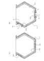
次に後者のものでは通気部51を有するスチール板を曲げ加工してスチール製筐体41を製作後、通気部51にライニング材が流入しないよう、またライニング完成後にライニング46にも同様の通気部52が形成されるよう、通気部51、52にダミー型を嵌合してライニング材を注型する。ライニング固化後ダミー型を取り除き、通気部52に研磨石やワークが通過不能な小孔4を有するポリウレタンピース5をボルト留めして形成する。しかしながらスチール製筐体41の曲げ加工精度には限界があり、加工後にスプリングバックなどによるひずみが生じることがある(図5)。そのためライニング完成後の通気部51、52周りを見ると、一方の通気部51が本来の位置からずれライニング肉厚に差が生じ、そこへ小孔4付ポリウレタンピース5をボルト固定すると、ピース5の肉厚と通気部52のライニング肉厚とに段差ができてしまう。段差ができると前述の偏磨耗の原因となるため好ましくない。特に蓋を押圧閉鎖したときは筐体41上方から力がかかるため、ひずみ度合いが著しくなって、段差が大きくなったり、ひどい場合には隙間が生じて好ましくない。
Next, in the latter case, after the steel plate having the
また乾式バレル研磨では、研磨石とワークが高速でバレル槽内を流動し、ライニング壁にも衝突を繰り返す。そのためワークが軟らかいものであると打痕が生じることがある。従来の湿式研磨であれば水が緩衝剤となるのでそのようなことも少なかった。そのため湿式研磨用バレル槽は耐磨耗性の観点から硬度の高いものを使用しても問題なく使うことができたが、乾式バレル研磨にあっては同様の硬度のものを使うと打痕の問題が起きてしまう。 In dry barrel polishing, the polishing stone and the workpiece flow in the barrel tank at high speed and repeatedly collide with the lining wall. Therefore, if the workpiece is soft, a dent may occur. In the case of conventional wet polishing, water becomes a buffering agent, so that is not so much. For this reason, the barrel tank for wet polishing can be used without problems even if it uses a high hardness from the viewpoint of wear resistance, but when using a barrel with the same hardness for dry barrel polishing, A problem will occur.
本発明は上記のような事情に基づいて完成されたものであって、ワークに打痕が生じにくいバレル槽の容器の製造方法を提供することを目的とする。 This invention is completed based on the above situations, Comprising: It aims at providing the manufacturing method of the container of the barrel tank which is hard to produce a dent in a workpiece | work.
上記の目的を達成するための手段として、請求項1の発明は、側面に外気の流通用通気部が形成された乾式バレル研磨用容器の製造方法であって、開閉可能な金型と中子とを、その両間に前記容器の成形空間を保有しつつ対向させ、かつこの成形空間のうち前記通気部の対応箇所にはダミー型を配した後に、前記成形空間へ溶融ポリウレタン樹脂を流し込み、その固化後に前記金型と中子とを開放して成形品を取り出し、しかる後に前記ダミー型によって形成された開口部に対し別途成形され前記通気部となる小孔が貫通形成されたポリウレタンピースを、その内面を周囲と面一にした状態で嵌着することを特徴とするものである。
As a means for achieving the above object, the invention of
また、請求項2の発明は、請求項1記載のものにおいて、前記金型における前記ダミー型と対向する箇所には、前記ポリウレタンピースを取付け可能なスチール製プレートが固着され、その状態で前記ポリウレタン樹脂が流し込まれることにより、前記プレートがインサートされた状態の成形品を得、しかる後に前記プレートを介して前記ポリウレタンピースの取付けがなされることを特徴とするものである。 According to a second aspect of the present invention, in the first aspect of the present invention, a steel plate to which the polyurethane piece can be attached is fixed to a portion of the mold facing the dummy mold, and the polyurethane plate is fixed in that state. A molded product in which the plate is inserted is obtained by pouring resin, and then the polyurethane piece is attached through the plate.
<請求項1の発明>
本発明は成形後にスプリングバックなどのひずみが生じない注型成形によって容器全体を製作したので、通気部があっても肉厚は均一に保たれ、後から小孔付ピースを嵌合しても段差が生じない。
<Invention of
In the present invention, since the entire container is manufactured by casting which does not cause distortion such as springback after molding, the thickness is kept uniform even if there is a vent, and even if a piece with a small hole is fitted later There is no step.
<請求項2の発明>
ポリウレタンピースはスチール製プレートを介して取付けがなされるようにしたため、取付けが簡単であるとともに、通気部回りの補強も併せて図られる、という効果が得られる。
<Invention of
Since the polyurethane piece is attached via the steel plate, it is easy to attach and the reinforcement around the ventilation portion can be achieved.
次に本発明の実施形態について図6〜10を参照しながら説明する。 Next, an embodiment of the present invention will be described with reference to FIGS.
図6の1は本発明のバレル槽を示す。このバレル槽1は容器2と蓋3とからなる。容器2は弾性材からなり、ここではポリウレタン樹脂を後述の注型製作法によって構成してある。このポリウレタン樹脂は硬さが、JIS K 6253のデュロメータ硬さタイプAで70となっている。乾式バレル研磨では緩衝剤となる水がないため、ワークが強い衝撃で容器2壁面に衝突するので打痕が生じやすい。しかし容器2の硬度をこのように設定すれば打痕を減少することができる。硬度については、60未満では機械的強度の問題で性能が劣る。また80を超えると打痕が生じやすくなるので、デュロメータ硬さタイプAで60から80の範囲が好ましい。この例では容器2の材質にポリウレタン樹脂を使用したが、その他にポリエステル樹脂など、注型成形によって固化できる熱硬化性樹脂が使用できる。
6 of FIG. 6 shows the barrel tank of the present invention. The
また容器2は断面6角形となっており、容器2を補強するために両端部が厚肉部2aとなっている。また容器2の周方向のうち2面には通気部25a、25bが形成されている。この通気部25a、25bは大きな開口となっており、例えば研磨石及び/またはワークが通過できるほどの大きさとなっている。これら通気部25a、25bの周囲にはスチール製のプレート6a、6bがポリウレタンの注型とともに容器2に埋め込まれている。また通気部25a、25bには研磨石及びワークが通過不能な小孔4を有するポリウレタンピース5a、5bが容器内部から嵌合可能になっており、プレート6a、6bにボルト、ナットを介して固定されている。なおポリウレタンピース5a、5b及びこれらの小孔4も注型成形によって製作する。
The
一方容器2の開口部2bは周方向の1面を利用しており、ここからワークと研磨石が投入される。この開口部2bは蓋3を閉鎖したときに開口部2bを密閉できるよう突起状に形成されたシール2cとなっている。シール2cの周囲には補強目的で矩形状のフレーム7がポリウレタンの注型とともに容器2に埋め込まれているが、必ずしも必要ではない。そしてフレーム7にはコネクティングプレート24がねじ止めされ、容器持ち運び用バー8が取り付けられている。
On the other hand, the opening 2b of the
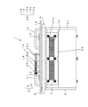
次に本発明の容器2の製作方法について図14を基に説明する。ここでは金型30の内面は容器2の形状になっており、注型材料が冷却固化して容器2となった後に取り出せるように30a、30b、30cに分割される。金型30の上端にはブリッジ31が架渡され、このブリッジ31に中子32が吊下げられる。中子32も容器2が冷却固化後に容器から取り出せるよう32a、32bに分割される。またプレート6a、6b及びフレーム7は相当する箇所の金型に図示しないがネジ固定されている。通気部25a、25bに相当する箇所にはダミー型33a、33bをプレート6a、6bを介して取り付け、ダミー型33a、33bとプレート6a、6bをプラスした肉厚が容器2と同じ肉厚になっている。
Next, the manufacturing method of the
これらの金型30、ブリッジ31、中子32、プレート6a、6b、フレーム7、ダミー型33a、33bをセット後、溶融ポリウレタン樹脂を流し込む。樹脂が固化したら中子32、ブリッジ31、金型30、ダミー型33a、33bの順に分解すると本発明のバレル槽容器2となる。
After setting the
次に蓋3について図6〜10を参照しながら説明する。蓋3の基部10はアルミなどの軽量合金で構成され、容器2に面する側には容器2と同材質のポリウレタンライニング9が注型成形により貼着されている。基部10の上面には取っ手11が2箇所設けられ、蓋3を着脱しやすくなっている。蓋3を容器2に閉鎖するには、後述するクランプシャフト21で押圧するため、クランプシャフト21が当たる面にはフリクションプレート12を備えている。また基部10にはクランプシャフト21を回動して蓋3を閉鎖するための、クランプシャフトのロック機構26が設けられている。このロック機構26はロッド13にスプリング14が取着され、スプリング14が挿通プレート15a、15b間にあって常時ロッド13を挿通プレート15c方向に負勢している。
Next, the
次に、蓋3の閉鎖機構について図11、図12を参照しながら説明する。16はバレル槽1を収容するバレルケースで自転シャフト17a、中空自転シャフト17bに取り付けられている。バレルケース16内には仕切り板18が一定空間を置いて設けられ、矩形状のスポンジゴム19を介してバレル槽1を支持するようになっている。またスポンジゴム19の内側は、仕切り板18がスポンジゴム同様に矩形状に切り欠いてあって切欠き18aとなっている。一方、バレルケース16の上端にはサイドプレート20がボルト固定され、クランプシャフト21を回動可能に保持するようになっている。クランプシャフト21には回動軸に対し偏芯カム22が形成され、サイドプレート20に差し込んだ時に中央の把持シャフト21aを持って矢示A方向へ回動すると、偏芯カム22が蓋3のフリクションプレート12を押圧して容器2に対し蓋3を閉鎖する。このとき容器2の底面にはスポンジゴム19があるのでスポンジゴム19が圧縮されることによってバレル槽1と仕切り板18との間を気密保持する。
Next, the closing mechanism of the
このようなバレル槽1はバレルケース16内に収容され、自転シャフト17a、中空自転シャフト17bを2枚の公転ターレット23の円周上に等間隔で自転可能に取り付け、この例では4箇所に配置してある(図13)。
Such a
さて、次にこのバレル槽1を用いてワークを研磨する場合について説明する。容器2の開口部2bより研磨石とワークを投入する。次にバレル槽1をバレルケース16に搭載し、蓋3を開口部2bに載せる。次にクランプシャフト21をサイドプレート20に差し込んで、把持シャフト21aを持って矢示A方向に回動すれば、バレル槽1はバレルケース16に固定される。またロック機構26のロッド13を予めスプリング14に抗して退避させておき、把持シャフト21aを回動した後ロッド13を復帰させれば、把持シャフト21aはロッド13によって固定され、跳ね返りを防止できる。この状態でターレット23を矢示D方向へ公転するとともに自転シャフト17a、中空自転シャフト17bを矢示E方向へ自転させるとバレル槽1は自公転作用を受けてワークを研磨する。
Next, a case where a workpiece is polished using the
ところでバレル槽1には通気部25a、25bがある。そして通気部25bは仕切り板18に面しており、仕切り板18には切欠き18aがあって、中空自転シャフト17bの中空部と仕切り板18下面を介して空間的に繋がっている。中空自転シャフト17bの先は図示しない集塵機に接続されており、研磨中、集塵機が作用してバレル槽1に対しエアーを吸引して研磨屑や粉塵を通気部25bに嵌合しているポリウレタンピース5bの小孔4より排出し、排気路B、Cのように通って集塵機へ回収される。この時、バレル槽1の底面ではスポンジゴム19が圧縮されて容器2と仕切り板18との間を気密保持しているので、エアーの流れは排気路B、Cのようにスムーズに流れる。一方、集塵作用に伴って通気部25aのポリウレタンピース5aの小孔4からはエアーが導入されるのでエアーの導入によってバレル槽1内部が冷却されるとともに研磨屑や粉塵が排出されるので研磨石は目詰まりせず、またワークも汚れ付着がなく良好に研磨される。
By the way, the
この例ではポリウレタンピース5a、5bをプレート6a、6bにボルト固定したがプレート6a、6bは必ずしも必要なく、ポリウレタンピース5a、5bを通気部25a、25bに直接取り付けてもよい。また上記の例ではバレル槽1を自公転する装置に取り付けたが、自転のみする回転バレル研磨装置に取り付けてもよい。通気部の数は1つまたは2つ以上形成してもよく、要するにエアーの導入と研磨屑や粉塵の排出ができればよい。
In this example, the polyurethane pieces 5a and 5b are bolted to the plates 6a and 6b. However, the plates 6a and 6b are not always necessary, and the polyurethane pieces 5a and 5b may be directly attached to the ventilation portions 25a and 25b. In the above example, the
以上のように、本発明に係る乾式バレル研磨用バレル槽は、従来のスチール製筐体を用いず注型成形によって容器全体を形成したので、容器の一部に通気部があっても肉厚は均一に保たれ、後から同肉厚の小孔を有するピースを嵌合しても段差が生じない。しかも容器がポリウレタン樹脂などの弾性材によって構成されているので軽量で、持ち運びの作業負担を軽減できる。また耐磨耗性が高いポリウレタン樹脂を使用すれば長期間にわたってバレル槽を使用することができ、スチール製筐体のバレル槽に比べポリウレタン肉厚も厚いので一層長期間の使用に耐える。さらにポリウレタン樹脂硬度をデュロメータ硬さタイプAで60から80としたので、湿式バレルに比べ緩衝作用をするものがない乾式バレルでもワークが容器内壁にぶつかる衝撃が和らげられ、打痕の減少につながる。 As described above, the barrel tank for dry barrel polishing according to the present invention formed the entire container by casting without using a conventional steel casing. Is kept uniform, and a step does not occur even if a piece having a small hole of the same thickness is fitted later. Moreover, since the container is made of an elastic material such as polyurethane resin, it is lightweight and can reduce the burden of carrying work. If a polyurethane resin with high wear resistance is used, the barrel tank can be used over a long period of time, and the polyurethane wall thickness is thicker than that of a steel casing barrel tank, so that it can withstand long-term use. Furthermore, since the polyurethane resin hardness is 60 to 80 in the durometer hardness type A, the impact of the workpiece hitting the inner wall of the container is reduced even in a dry barrel that has no buffering action compared to the wet barrel, leading to a reduction in the dents.
1…バレル槽
2…容器
3…蓋
25a…通気部
25b…通気部
DESCRIPTION OF
Claims (2)
開閉可能な金型と中子とを、その両間に前記容器の成形空間を保有しつつ対向させ、かつこの成形空間のうち前記通気部の対応箇所にはダミー型を配した後に、前記成形空間へ溶融ポリウレタン樹脂を流し込み、その固化後に前記金型と中子とを開放して成形品を取り出し、しかる後に前記ダミー型によって形成された開口部に対し別途成形され前記通気部となる小孔が貫通形成されたポリウレタンピースを、その内面を周囲と面一にした状態で嵌着することを特徴とする乾式バレル研磨用容器の製造方法。 A method for producing a dry barrel polishing container in which a vent for circulation of outside air is formed on a side surface,
The mold and the core that can be opened and closed are opposed to each other while holding the molding space for the container therebetween, and a dummy die is disposed at a corresponding portion of the ventilation portion in the molding space, and then the molding is performed. A molten polyurethane resin is poured into the space, and after the solidification, the mold and the core are opened to take out a molded product, and then a small hole that is separately molded with respect to the opening formed by the dummy mold and serves as the ventilation portion A method for producing a dry barrel polishing container, comprising: inserting a polyurethane piece having a through hole in a state where its inner surface is flush with the periphery.
Priority Applications (1)
| Application Number | Priority Date | Filing Date | Title |
|---|---|---|---|
| JP2003333508A JP3779708B2 (en) | 2003-09-25 | 2003-09-25 | Manufacturing method of dry barrel polishing container |
Applications Claiming Priority (1)
| Application Number | Priority Date | Filing Date | Title |
|---|---|---|---|
| JP2003333508A JP3779708B2 (en) | 2003-09-25 | 2003-09-25 | Manufacturing method of dry barrel polishing container |
Related Parent Applications (1)
| Application Number | Title | Priority Date | Filing Date |
|---|---|---|---|
| JP2000225779A Division JP2002036095A (en) | 2000-07-26 | 2000-07-26 | Barrel vessel for dry barrel polishing |
Publications (2)
| Publication Number | Publication Date |
|---|---|
| JP2004042664A JP2004042664A (en) | 2004-02-12 |
| JP3779708B2 true JP3779708B2 (en) | 2006-05-31 |
Family
ID=31712766
Family Applications (1)
| Application Number | Title | Priority Date | Filing Date |
|---|---|---|---|
| JP2003333508A Expired - Fee Related JP3779708B2 (en) | 2003-09-25 | 2003-09-25 | Manufacturing method of dry barrel polishing container |
Country Status (1)
| Country | Link |
|---|---|
| JP (1) | JP3779708B2 (en) |
Families Citing this family (2)
| Publication number | Priority date | Publication date | Assignee | Title |
|---|---|---|---|---|
| JP5049171B2 (en) * | 2008-03-17 | 2012-10-17 | 株式会社チップトン | Barrel polishing machine |
| WO2015064158A1 (en) | 2013-10-30 | 2015-05-07 | 新東工業株式会社 | Barrel tank for centrifugal barrel machine, method for producing same, and centrifugal barrel polishing machine |
-
2003
- 2003-09-25 JP JP2003333508A patent/JP3779708B2/en not_active Expired - Fee Related
Also Published As
| Publication number | Publication date |
|---|---|
| JP2004042664A (en) | 2004-02-12 |
Similar Documents
| Publication | Publication Date | Title |
|---|---|---|
| JP2002036095A (en) | Barrel vessel for dry barrel polishing | |
| JP4422184B2 (en) | Die-casting mold, die-casting mold manufacturing method, and die-cast casting mold-using casting method | |
| JP3779708B2 (en) | Manufacturing method of dry barrel polishing container | |
| JP2649567B2 (en) | Lining plate for mold space of frameless molding machine | |
| US6860315B2 (en) | Green sand casting method and apparatus | |
| CN109641267A (en) | Casting system | |
| CN213591734U (en) | Quick-filling casting without sand hole and shrinkage porosity | |
| WO2004099612A2 (en) | Hard material impeller and methods and apparatus for construction | |
| CN110561039A (en) | electronic product component and processing method thereof | |
| JPH0857628A (en) | Method for pre-treating removal of core in aluminum casting | |
| CN106001498B (en) | The compression casting method of ball grinding machine lining board | |
| CN216179131U (en) | 360-degree rotary blowing device after deburring of hard alloy | |
| CN213798288U (en) | Novel maintenance apron and forming die thereof | |
| CN112872329B (en) | Low-pressure casting die for compressor shell | |
| CN1286569C (en) | Raymond mill hammer and casting process thereof | |
| CN215237658U (en) | Bimetal tup casting sand mould molding device | |
| CN218310824U (en) | Casting device for casting anti-deformation castings | |
| CN218329871U (en) | Mould aperture detection device | |
| JP4146805B2 (en) | Fishing spinning reel | |
| JP2001009563A (en) | Metal molding die, and manufacture thereof, and metal molding method | |
| JP3181772U (en) | Ball mill equipment | |
| CN212019313U (en) | Detachable cast copper mold | |
| JP3159290B2 (en) | Mold device for mold making and upper mold manufacturing method | |
| CA2494036A1 (en) | A method for casting objects with an improved riser arrangement | |
| JPH09253796A (en) | Device for fastening mold |
Legal Events
| Date | Code | Title | Description |
|---|---|---|---|
| A621 | Written request for application examination |
Free format text: JAPANESE INTERMEDIATE CODE: A621 Effective date: 20030926 |
|
| A131 | Notification of reasons for refusal |
Free format text: JAPANESE INTERMEDIATE CODE: A131 Effective date: 20051213 |
|
| A521 | Written amendment |
Free format text: JAPANESE INTERMEDIATE CODE: A523 Effective date: 20060201 |
|
| TRDD | Decision of grant or rejection written | ||
| A01 | Written decision to grant a patent or to grant a registration (utility model) |
Free format text: JAPANESE INTERMEDIATE CODE: A01 Effective date: 20060223 |
|
| A61 | First payment of annual fees (during grant procedure) |
Free format text: JAPANESE INTERMEDIATE CODE: A61 Effective date: 20060302 |
|
| R150 | Certificate of patent or registration of utility model |
Free format text: JAPANESE INTERMEDIATE CODE: R150 Ref document number: 3779708 Country of ref document: JP Free format text: JAPANESE INTERMEDIATE CODE: R150 |
|
| RD04 | Notification of resignation of power of attorney |
Free format text: JAPANESE INTERMEDIATE CODE: R3D04 |
|
| FPAY | Renewal fee payment (event date is renewal date of database) |
Free format text: PAYMENT UNTIL: 20120310 Year of fee payment: 6 |
|
| R250 | Receipt of annual fees |
Free format text: JAPANESE INTERMEDIATE CODE: R250 |
|
| FPAY | Renewal fee payment (event date is renewal date of database) |
Free format text: PAYMENT UNTIL: 20120310 Year of fee payment: 6 |
|
| FPAY | Renewal fee payment (event date is renewal date of database) |
Free format text: PAYMENT UNTIL: 20150310 Year of fee payment: 9 |
|
| R250 | Receipt of annual fees |
Free format text: JAPANESE INTERMEDIATE CODE: R250 |
|
| R250 | Receipt of annual fees |
Free format text: JAPANESE INTERMEDIATE CODE: R250 |
|
| R250 | Receipt of annual fees |
Free format text: JAPANESE INTERMEDIATE CODE: R250 |
|
| LAPS | Cancellation because of no payment of annual fees |