JP3778673B2 - Drilling end mill and drilling equipment - Google Patents
Drilling end mill and drilling equipment Download PDFInfo
- Publication number
- JP3778673B2 JP3778673B2 JP28185397A JP28185397A JP3778673B2 JP 3778673 B2 JP3778673 B2 JP 3778673B2 JP 28185397 A JP28185397 A JP 28185397A JP 28185397 A JP28185397 A JP 28185397A JP 3778673 B2 JP3778673 B2 JP 3778673B2
- Authority
- JP
- Japan
- Prior art keywords
- excavation
- end mill
- shaft portion
- bit
- axis
- Prior art date
- Legal status (The legal status is an assumption and is not a legal conclusion. Google has not performed a legal analysis and makes no representation as to the accuracy of the status listed.)
- Expired - Fee Related
Links
Images


Landscapes
- Road Repair (AREA)
Description
【0001】
【発明の属する技術分野】
本発明は、道路その他の舗装面等を掘削する掘削用エンドミルおよび掘削装置の改良に関する。
【0002】
【従来の技術】
道路工事や、上下水道管、電力管、通信管、ガス管などの埋設工事においては、既に舗装された地面を掘り返す工事が必要となることがある。このような工事で使用される掘削装置としては、例えば、本出願人による特願平8−258896号に提案がなされている。
【0003】
図10、図11には、この掘削装置を示す。
【0004】
図示されるように、この掘削装置では、パワーショベル等の油圧作業機本体1のアーム2先端のホルダ5に油圧モータ3が着脱可能に装着される。そして、この油圧モータ3のモータシャフト3Aに、舗装面の掘削及び切削を行うエンドミル104が同軸的に取り付けられる。
【0005】
アーム2は、互いに連結したアーム部2A、2Bから構成され、複数の油圧シリンダ6A、6B、6Cの伸縮動作により、任意の角度に屈曲するようになっている。また、油圧モータ3はホルダ5に対してフランジ部3Bに締結したボルト等により固定される一方、油圧シリンダ6A、6B、6C等と共に、油圧作業機本体1に備えた図示しない油圧源からの作動油の供給を受け、エンドミル104を回転駆動する。なお、この油圧モータ3への作動油の供給は、図示しない制御弁により制御される。
【0006】
エンドミル104は、モータシャフト3Aに嵌合する図示されない結合軸部の下方に、エンドミル本体107を備える。そして、このエンドミル本体107の先端面(掘削面)111には2種類の掘削ビット121A、121Bが、また外周側面(切削面)112にはビット列を形成した切削ビット122が、それぞれ備えられている。
【0007】
このような構成により、舗装面の掘削(穿孔)作業をするときには、アーム2の操作により、エンドミル104を掘削作業をすべき舗装面に垂直にセットし、そのまま垂直方向に回転させつつ押し込めば、掘削ビット121A、121Bにより掘削穴を掘ることができる。また、このエンドミル104を垂直に保持したまま、アーム2の操作で舗装面と平行に移動させれば、切削面112の切削ビット122により、所定の深さ及び幅をもって舗装面を切削または切断できる。
【0008】
【発明が解決しようとする課題】
しかしながら、このような掘削装置による掘削作業では、アーム2の操作でエンドミル104を舗装面に完全に垂直な方向に送り出し続けることは難しい。このため、この掘削装置では、図12に示すように、エンドミル104は、略垂直に掘られた掘削穴100に対して傾いてしまい、エンドミル本体107の外周側面112および切削ビット122が掘削穴100の上端部付近の内周に接触する。
【0009】
この結果、エンドミル104の回転に抵抗がかかってトルクロスが生じてしまうとともに、エンドミル本体107には曲げ力がかかり、エンドミル104の破損が早まってしまう。
【0010】
また、外周側面112には、切削ビット122のビット列が外周方向に沿って断続的に設けられているので、このビット列による外周側面112の凹凸により、エンドミル104には回転に伴う振動が発生しやすく、このような振動は、掘削装置の操作性を悪化させる原因となってしまう。
【0011】
一方、このような掘削工具の傾きが生じないように、掘削工具を舗装面に対して一定の角度を保って直線的に送り出す送り機構を備えた掘削装置および刃具として、例えば、図13または図14に示すようなものが知られいる。
【0012】
このうち図13に示したものは、コンクリート破砕機130に備えられるもので、先端面に刃具131を備えた回転穿孔機132は保持ブラケット133に固定される。この保持ブラケット133は、ハンドル134の操作による回転ネジ軸135の回転により、機体136内を回転ネジ軸135に沿って真っすぐに送り出される。これにより、回転穿孔機132は舗装面に対して一定の角度を保って直線的に送り出し続けられる。しかしながら、このような掘削装置では、回転穿孔機132を送り出すための保持ブラケット133や回転ネジ軸135等からなる複雑な送り機構が必要となり、上述のアーム操作式の掘削装置のような簡便さや自由度の高さは得られない。
【0013】
また、図14に示すように、円筒形のドリル本体141の先端に、環状の掘削刃具142を備えた、いわゆるコアドリル140を備えた掘削装置も知られている。しかしながら、この掘削装置においても、やはり図示されない送り機構が必要となる。さらに掘削作業後には、掘削穴100の内側にコアドリル140の中空部に対応した掘削屑101(図に格子縞で示す)が残ってしまい、これを除去する必要があるので作業効率が低下してしまう。
【0014】
本発明は、このような問題点に着目してなされたもので、油圧作業機のアーム先端に備えられたエンドミルにより掘削作業を行う掘削装置において、エンドミルに曲げ力がかからず、またエンドミルに不要な振動が生じないようにした掘削用エンドミルおよび掘削装置を提供することを目的とする。
【0016】
【課題を解決するための手段】
第1の発明では、前記シャフト部の外周側面に少なくとも1本の切削ビット列を備えるとともに、この切削ビット列の高さは前記先端面外周よりもエンドミルの軸に対して外側に出ないように十分低くした。
【0017】
第2の発明では、前記切削ビットの少なくとも1本は前記掘削方向の軸に平行に設けられる。
【0018】
第3の発明では、前記切削ビットの少なくとも1本は前記掘削方向の軸を中心とする螺旋状に設けられる。
【0019】
第4の発明では、前記先端面に開口するとともに、前記掘削方向の軸に対して所定の角度で傾斜し、前記シャフト部の側面に開口する排出通路を備えた。
【0020】
第5の発明では、前記排出通路は前記掘削方向の軸上で前記掘削ビットに囲まれた間隙部に開口するとともに、前記排出通路の径をこの間隙部の径よりも大きくした。
【0021】
第6の発明では、前記掘削ビットは前記掘削方向の軸上に位置決め用の頂点を備えた。
【0022】
第7の発明では、基端側の結合軸部において駆動手段と結合し回転駆動されるとともに、先端面に掘削ビットを備えた掘削用エンドミルにおいて、前記結合軸部と前記先端面との間のシャフト部の軸方向の一部を柔軟性のある材料からなる継ぎ手とした。
【0023】
第8の発明では、油圧駆動される油圧作業機本体と、この油圧作業機本体に設けられたアームと、このアームのホルダに着脱可能に装着される油圧モータと、油圧作業機本体の油圧源からの油圧を前記油圧モータに供給する手段とを備えるとともに、前記第1から第7の発明のいずれか一つの掘削用エンドミルを前記油圧モータを前記駆動手段として回転駆動する。
【0024】
【発明の作用および効果】
第1の発明では、掘削用エンドミルは駆動手段により回転駆動され、先端面に備えられた掘削ビットにより掘削面を掘削して行くが、エンドミルのシャフト部は掘削ビットが設けられた先端面よりも小径であるので、シャフト部外周と掘削された掘削穴内周との間には十分な余裕があり、掘削作業中に掘削方向に対して掘削用エンドミルの中心軸が多少傾いてしまったとしても、シャフト部は掘削穴の端部や内周に接触することはない。
【0025】
したがって、掘削用エンドミルの回転には、掘削穴との接触による抵抗が加わることはなく、トルクロスが生じることはない。また、掘削穴との接触によって掘削用エンドミルに曲げ力がかかってしまうこともなく、掘削用エンドミルの耐久性が向上する。また、掘削用エンドミルは、掘削穴との接触によって振動してしまうこともない。
【0026】
第1から第3の発明では、シャフト部外周に設けられた切削ビット列は十分に低い高さとされているので、掘削用エンドミルが多少傾いたとしても掘削穴内周と接触することはなく、掘削作業に支承を与えることはない一方、エンドミルの傾斜角度がシャフト部外周と掘削穴内周との余裕を超えて大きくなってしまったときには、切削ビット列は掘削穴内周を削り、シャフト部には過大な力がかかることはない。
【0027】
また第3の発明のように、切削ビット列を螺旋状に設ければ、切削ビットは掘削用エンドミルの外周方向に連続的に配置されるので、掘削穴内周面と接触したときでもその接触は断続的とならず、掘削用エンドミルに大きな振動が生じてしまうことはない。また、螺旋状の切削ビット列により切削屑を上方に弾き出すことができるので、切削屑の排出性が向上する。
【0028】
第4、第5の発明では、掘削屑は掘削が進むにしたがって排出通路に送り込まれ、排出通路の内周面に当たって細かく粉砕され、シャフト部側面の開口から排出される。さらに掘削屑は、シャフト部に設けられた切削ビット列によりさらに細かく粉砕されてから、掘削穴の外部に排出される。したがって、本発明によれば、掘削屑は効率的に排出されるので、掘削作業の作業効率が高められる。
【0029】
また第5の発明のように、排出通路の径を間隙部の径よりも大きくしておくと、掘削屑の排出性をより高めることができる。
【0030】
第6の発明では、掘削作業開始時において、掘削用エンドミルは頂点により掘削面に対して水平方向に確実に位置決めされる。これにより、掘削ビットによる掘削開始時に舗装面から受ける反力によっても、エンドミルは左右に位置ずれすることはなく、作業効率が著しく向上する。
【0031】
第7の発明では、掘削用エンドミルのシャフト部の一部は柔軟な継ぎ手となっているので、操作ミス等によりエンドミルを傾けてしまったときにも、エンドミルにかかる負荷は継ぎ手において吸収され、シャフト部、掘削ビット、切削ビット等の破損を防止できる。また、エンドミルのシャフト部は継ぎ手のところで折れ曲がって、この傾斜を吸収するので、エンドミルの継ぎ手より先の部分は、真っすぐに掘削方向を向き、そのまま掘削作業を続行することができる。さらに、掘削作業中にエンドミルに生じる振動は、継ぎ手において吸収され、掘削装置の他の構成部分に伝わらないため、掘削装置の操作性が向上する
【0032】
第8の発明によれば、掘削用エンドミルを油圧作業機のアームで操作できるので、エンドミルは任意の姿勢並びに方向へ制御でき、自由度の高い掘削作業が行えるが、このアーム操作では、エンドミルを掘削方向に対して真っすぐに維持し続けることは難しい。ところが、本発明では、第1から第7の発明の掘削用エンドミルが用いられているので、エンドミルが掘削方向に対して傾いてしまったとしても、エンドミルのシャフト部は掘削穴と接触してしまうことはない。したがって、掘削用エンドミルの回転には、掘削穴との接触による抵抗が加わることはなく、トルクロスが生じることはない。また、掘削穴との接触によって掘削用エンドミルに曲げ力がかかってしまうこともなく、掘削用エンドミルの耐久性が向上する。また、掘削用エンドミルは、掘削穴との接触によって振動してしまうこともない。
【0033】
【発明の実施の形態】
以下、添付図面に基づいて、本発明の実施の形態について説明する。
【0034】
なお、以下の各実施の形態においては、掘削装置の全体構成は、例えば図10に示すものと同様である。したがって、以下の説明においては、本発明の特徴となるエンドミルの構成を中心に説明する。
【0035】
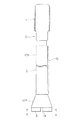
図1〜図3には、本発明の第1の実施の形態のエンドミル10を示す。
【0036】
図示されるように、略円柱形状のエンドミル10は、基端側に結合軸部11を備え、また、この結合軸部11から一体に延び、掘削または切削用の刃具であるビットが取り付けられるエンドミル本体12を備えている。エンドミル10は、結合軸部11において、油圧モータ3のモータシャフト3Aに、スプラインまたはネジ等の締結手段によって一体に結合され、モータシャフト3Aの回転がエンドミル10に伝達されるようになっている。
【0037】
エンドミル本体12は、結合軸部11側から一体に延び出した外径の小さなシャフト部12Aと、このシャフト部12Aからテーパ状に広がり、エンドミル10の先端部となるテーパ部12Bとから構成される。エンドミル10の先端面は、このテーパ部12Bのエンドミル軸と垂直な端面であり、この先端面に複数の掘削ビット13が取り付けられている。
【0038】
図2に示すように、掘削ビット13は略扇形断面を備え、これらの掘削ビット13の間は、エンドミル先端面の半径方向に延びる排出溝14で隔てられている。なお、掘削ビット13はこのような扇型断面のビットに限られるものではなく、任意の形状のビットを適宜使用することができる。
【0039】
また、シャフト部12Aの外周側面には、エンドミル10の軸方向に延びる複数の切削ビット列15が設けられている。これらの切削ビット列15は、例えば、ダイヤモンド粒子、超硬金属粒子等の高硬度材料からなる複数の切削ビットを溶着等の手段によりシャフト部12A外周に固設して形成される。
【0040】
この切削ビット列15の高さは十分低く、エンドミル先端面の外周よりも内側(エンドミルの軸側)に入るようにする。なお、図1、図2では、これらの各切削ビットの詳細な図示は省略し、切削ビット列15の外形(配設位置)のみを示している。
【0041】
つぎに作用を説明する。
【0042】
舗装面を掘削するときには、まず、油圧シリンダ6A、6B、6Cを伸縮させることでアーム2を操作し、エンドミル10を所定の掘削場所に移動させる。続いて、舗装面に垂直にエンドミル10をセットするとともに油圧モータ3により回転させ、そのまま鉛直方向に押し込むことにより、掘削ビット13により掘削作業を実行する。
【0043】
このようにして、掘削穴100は略鉛直方向を掘削方向として掘り進められるが、図4に示すように、この掘削作業中にエンドミル10が鉛直方向に対して傾いてしまうことがある。
【0044】
ところが、本発明では、エンドミル本体12の全長の大部分は、エンドミル先端面(テーパ部12Aの端面)よりも外径が小さいシャフト部12Aとなっているので、シャフト部12Aの外周と掘削穴100の内周との間には十分な余裕がある。このため、エンドミル10が多少傾いたとしても、シャフト部12Aは掘削穴100の上端部側の内周に接触することはない。
【0045】
したがって、エンドミル10の回転には抵抗が加わることはなく、トルクロスが生じることはない。また、エンドミル本体12に曲げ力がかかってしまうこともなく、エンドミル10の耐久性が向上する。また、エンドミル10は、掘削穴100との断続的接触により振動してしまうこともない。
【0046】
なお、シャフト部12A外周の切削ビット列15は十分に低い高さとされているので、エンドミル10が多少傾いたとしても掘削穴100内周と接触することはない。一方、エンドミル10の傾斜角度がシャフト部12Aの外周と掘削穴100の内周との余裕を超えて大きくなってしまったときには、切削ビット列15が、掘削穴100内周を削るので、シャフト部12Aには過大な力がかからないようになっている。
【0047】
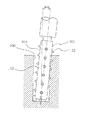
図5には、本発明の第2の実施の形態を示す。
【0048】
この実施の形態では、上記第1の実施の形態の基本構成に加えて、掘削屑を排出するための排出通路16を備えている。この排出通路16からは、複数の掘削ビット13に囲まれたエンドミル10の中心軸上の間隙部17に残された削り残しが排出される。
【0049】
さらに詳しく説明すると、排出通路16は、間隙部17の上方に、エンドミル10の軸に対して所定の角度θで傾斜して延び出し、シャフト部12A側面に貫通して、広く開口している。これにより、掘削ビット13の真ん中の間隙部17に残された削り残しは、掘削が進むにしたがって排出通路16に達する。そして、排出通路16の内周面に当たって細かく粉砕され、下方の削り残しに押し出されるようにして、シャフト部12A側面の開口から排出される。このように排出された掘削屑は、シャフト部12Aに設けられた切削ビット列15によりさらに細かく粉砕されてから、掘削穴100の外部に排出される。なお、排出通路16の径φBを、間隙部17の径φAよりも大きくしておくと、掘削屑の排出性をより高めることができる。
【0050】
このように本実施の形態では、掘削ビット13の間に残された削り残しは、排出通路16から自動的に排出されるので、削り残しの除去作業は不要となり、掘削作業の作業効率が高められる。
【0051】
図6には、本発明の第3の実施の形態を示す。
【0052】
図示されるように、この実施の形態では、上記第1または第2の実施の形態の基本構成における切削ビット列15を、螺旋状の切削ビット列18に置き換えている。
【0053】
このように切削ビット列18を螺旋状に配置することにより、たとえ切削ビット列18が掘削穴100内周面に接触したとしても、切削ビット列18を構成する切削ビットはシャフト部12Aの外周に連続的に存在するので、この接触は断続的とはならず、エンドミル10を振動させてしまうことはない。
【0054】
また、図6に示すように、エンドミル10の回転方向に向かう切削ビット列18の側面が斜め上方を向くようにすれば、エンドミル10の回転に伴い、切削屑は切削ビット列18により上方に弾き出されるので、切削屑の排出性が高められる。
【0055】
なお、切削ビット列18は本実施の形態のように1本である必要はなく、複数の切削ビット列18を設け、切削性および切削屑の排出性をさらに高めるようにしてもよい。
【0056】
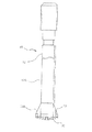
図7、図8には本発明の第4の実施の形態を示す。
【0057】
図示されるように、この実施の形態では、上記第1の実施の形態の基本構成に対して、複数の掘削ビット13を複数の掘削ビット20に置き換えている。
【0058】
これらの掘削ビット20は、三角形断面の刃の鋭角部分を下方に向けて、エンドミル10の先端面(テーパ部12Bの端面)の半径方向に沿って配設される。なお、この実施の形態では、掘削ビット20は4本であり、互いに90度の間隔をもって配設されている。
【0059】
さらに、これらの掘削ビット20はエンドミル10の中心軸に向かって所定の角度で傾斜し、全体として錐体を形成しており、エンドミル10の中心軸上に頂点21を形成している。これにより、エンドミル10による掘削開始時に、頂点21においてエンドミル10の位置決めをすることができる。すなわち、掘削ビットと掘削面との接触が面接触である場合には、掘削開始時にエンドミル10は位置が左右にずれやすいが、本実施の形態の掘削ビット20は、掘削開始時に舗装面と頂点21において点接触するので、エンドミル10の位置決めは容易かつ確実に行え、作業効率が著しく向上する。
【0060】
なお、この実施の形態では、テーパ部12B外周側面には、掘削ビット20の配置と互い違いとなるように、エンドミル10の軸に沿った方向に延びる排出溝22が形成され、これにより、掘削屑の排出性の向上が図られている。
【0061】
また、上述したとおり、本実施の形態では掘削ビット20は三角形断面のものを90度の間隔で配設しているが、当然、本発明はこのような実施形態に限るものではなく、掘削ビット20の刃形状として三角形断面以外の形状を用い、また、各掘削ビット20間の間隔も90度以外の角度とすることもできる。
【0062】
図9には、本発明の第5の実施の形態を示す。
【0063】
図示されるように、この実施の形態のエンドミル30は、剛体からなるエンドミル本体31の軸方向の一部が、例えばゴム等の柔軟性(弾性)を備えた材料からなる継ぎ手32となっている。なお、エンドミル30は、上記の各実施の形態と同様に、基端側の結合軸部34において油圧モータ3のモータシャフト3Aに取り付けられるものである。
【0064】
このような構成により、油圧作業機本体1のアーム2によりエンドミル30を操作するときに、操作ミス等によりエンドミル30を傾けてしまい、エンドミル30に大きな負荷がかかりそうになったとしても、この負荷は継ぎ手32において吸収されるので、エンドミル本体31や、エンドミル30先端の掘削ビット33や、エンドミル本体31外周面に配設された図示されない切削ビット列等の破損を防止できる。
【0065】
また、モータシャフト3Aが掘削方向に対して傾いてしまったときでも、エンドミル30は継ぎ手32のところで折れ曲がって、この傾斜を吸収するので、エンドミル30の継ぎ手32より先の部分は掘削方向を向き、掘削穴に沿って真っすぐであり続けるので、そのまま掘削作業を続行することができる。
【0066】
さらに、掘削作業中にエンドミル30に生じる振動は、継ぎ手32において吸収され、掘削装置の他の構成部分に伝わらないため、掘削装置の操作性は、エンドミル30の振動によって低下してしまうことはない。
【図面の簡単な説明】
【図1】本発明の第1の実施の形態のエンドミルを示す外形図である。
【図2】同じく図1のA−A断面図である。
【図3】同じくシャフト部の展開図である。
【図4】同じく本発明の作用を示す説明図である。
【図5】本発明の第2の実施の形態のエンドミルを示す断面図である。
【図6】本発明の第3の実施の形態のシャフト部の展開図である。
【図7】本発明の第4の実施の形態のエンドミルを示す側面図である。
【図8】同じく底面図である。
【図9】本発明の第5の実施の形態のエンドミルを示す一部断面図である。
【図10】掘削装置の全体構成を示す側面図である。
【図11】従来のエンドミルを油圧モータに装着した様子を示す側面図である。
【図12】従来例の問題点を示す説明図である。
【図13】従来の掘削装置を示す断面図である。
【図14】従来の掘削装置を示す断面図である。
【図15】従来例の問題点を示す説明図である。
【符号の説明】
1 油圧作業機本体
2 アーム
3 油圧モータ
3A モータシャフト
10 エンドミル
11 結合軸部
12 エンドミル本体
12A シャフト部
12B テーパ部
13 掘削ビット
14 排出溝
15 切削ビット列
16 排出通路
17 間隙部
18 切削ビット列
20 掘削ビット
21 頂点
22 排出溝
30 エンドミル
31 エンドミル本体
32 継ぎ手
33 掘削ビット
34 結合軸部
100 掘削穴[0001]
BACKGROUND OF THE INVENTION
The present invention relates to an improvement of an end mill for excavation for excavating roads and other pavement surfaces, and an excavator.
[0002]
[Prior art]
In road construction and burial work such as water and sewage pipes, power pipes, communication pipes, and gas pipes, it may be necessary to dig up the already paved ground. As an excavator used in such construction, for example, Japanese Patent Application No. 8-258896 proposed by the present applicant has been proposed.
[0003]
10 and 11 show this excavator.
[0004]
As shown in the figure, in this excavator, a
[0005]
The
[0006]
The
[0007]
With such a configuration, when performing excavation (drilling) work on the pavement surface, if the
[0008]
[Problems to be solved by the invention]
However, in such excavation work by the excavator, it is difficult to continue feeding the
[0009]
As a result, resistance is applied to the rotation of the
[0010]
Further, since the bit string of the
[0011]
On the other hand, as an excavator and a cutting tool having a feed mechanism that linearly feeds the excavation tool while maintaining a certain angle with respect to the pavement surface so that the tilt of the excavation tool does not occur, for example, FIG. 13 or FIG. 14 is known.
[0012]
Among these, the one shown in FIG. 13 is provided in the
[0013]
As shown in FIG. 14, a drilling device including a so-called
[0014]
The present invention has been made paying attention to such problems, and in an excavator that performs excavation work by an end mill provided at the tip of an arm of a hydraulic working machine, the end mill is not subjected to bending force, and the end mill An object of the present invention is to provide an end mill for excavation and an excavator that are free from unnecessary vibrations.
[0016]
[Means for Solving the Problems]
In the first aspect of the invention, at least one cutting bit row is provided on the outer peripheral side surface of the shaft portion, and the height of the cutting bit row is sufficiently lower than the outer periphery of the tip end surface so as not to protrude outward from the end mill shaft. did.
[0017]
In the second invention, at least one of the cutting bits is provided in parallel to the axis in the excavation direction .
[0018]
In a third aspect of the invention, at least one of the cutting bits is provided in a spiral shape with the axis in the excavation direction as the center.
[0019]
According to a fourth aspect of the present invention, there is provided a discharge passage that opens at the tip surface, is inclined at a predetermined angle with respect to the axis in the excavation direction , and opens at a side surface of the shaft portion.
[0020]
In the fifth aspect of the invention, the discharge passage opens into a gap surrounded by the excavation bit on the excavation direction axis , and the diameter of the discharge passage is made larger than the diameter of the gap.
[0021]
In a sixth aspect of the invention, the excavation bit has a positioning apex on the axis in the excavation direction .
[0022]
In the seventh invention, in the end mill for excavation, which is coupled to the driving means at the coupling shaft portion on the proximal end side and is rotationally driven, and which has a drilling bit on the distal end surface, between the coupling shaft portion and the distal end surface. A part of the shaft portion in the axial direction is a joint made of a flexible material.
[0023]
In an eighth aspect of the invention, a hydraulically operated hydraulic working machine main body, an arm provided on the hydraulic working machine main body, a hydraulic motor detachably attached to a holder of the arm, and a hydraulic power source of the hydraulic working machine main body Means for supplying hydraulic pressure from the hydraulic motor to the hydraulic motor, and the digging end mill according to any one of the first to seventh aspects of the invention is driven to rotate using the hydraulic motor as the driving means.
[0024]
Operation and effect of the invention
In the first invention, the end mill for excavation is rotationally driven by the driving means, and the excavation surface is excavated by the excavation bit provided on the front end surface, but the shaft portion of the end mill is more than the front end surface provided with the excavation bit. Because of the small diameter, there is a sufficient margin between the outer periphery of the shaft portion and the inner periphery of the excavated hole, and even if the central axis of the end mill for excavation is slightly inclined with respect to the excavation direction during excavation work, The shaft portion does not contact the end of the excavation hole or the inner periphery.
[0025]
Therefore, the rotation of the end mill for excavation is not subjected to resistance due to contact with the excavation hole, and no torcross is generated. Further, the bending force is not applied to the excavation end mill due to contact with the excavation hole, and the durability of the excavation end mill is improved. Further, the excavation end mill does not vibrate due to contact with the excavation hole.
[0026]
In the first to third inventions, the cutting bit row provided on the outer periphery of the shaft portion has a sufficiently low height, so even if the end mill for excavation is slightly inclined, it does not come into contact with the inner periphery of the excavation hole, and excavation work However, when the inclination angle of the end mill becomes larger than the margin between the outer periphery of the shaft and the inner periphery of the drilling hole, the cutting bit row cuts the inner periphery of the drilling hole and excessive force is applied to the shaft. Will not take.
[0027]
Further, as in the third aspect of the invention, if the cutting bit row is provided in a spiral shape, the cutting bit is continuously arranged in the outer peripheral direction of the end mill for excavation, so that the contact is intermittent even when contacting the inner peripheral surface of the excavation hole. There will be no significant vibration in the end mill for excavation. Moreover, since the cutting waste can be ejected upward by the spiral cutting bit string, the dischargeability of the cutting waste is improved.
[0028]
In the fourth and fifth inventions, the excavation waste is fed into the discharge passage as the excavation proceeds, hits the inner peripheral surface of the discharge passage, is finely pulverized, and is discharged from the opening on the side surface of the shaft portion. Further, the drilling waste is further finely pulverized by the cutting bit row provided in the shaft portion, and then discharged to the outside of the drilling hole. Therefore, according to the present invention, the excavation waste is efficiently discharged, so that the work efficiency of the excavation work is increased.
[0029]
Moreover, if the diameter of the discharge passage is made larger than the diameter of the gap portion as in the fifth invention, the excavation property of the excavation waste can be further improved.
[0030]
In the sixth invention, at the start of excavation work, the excavation end mill is reliably positioned in the horizontal direction with respect to the excavation surface by the apex. As a result, the end mill is not displaced from side to side due to the reaction force received from the pavement surface when starting excavation by the excavation bit, and the work efficiency is remarkably improved.
[0031]
In the seventh invention, since a part of the shaft portion of the end mill for excavation is a flexible joint, the load applied to the end mill is absorbed by the joint even when the end mill is tilted due to an operation error or the like. Can prevent damage to parts, drill bits, cutting bits, etc. Further, since the shaft portion of the end mill is bent at the joint and absorbs this inclination, the portion ahead of the end mill joint can be directly oriented in the excavation direction and the excavation work can be continued as it is. Further, vibration generated in the end mill during excavation work is absorbed by the joint and is not transmitted to other components of the excavator, so that the operability of the excavator is improved.
According to the eighth aspect of the invention, since the end mill for excavation can be operated with the arm of the hydraulic working machine, the end mill can be controlled in an arbitrary posture and direction, and excavation work with a high degree of freedom can be performed. It is difficult to keep it straight in the direction of excavation. However, in the present invention, since the end mill for excavation of the first to seventh inventions is used, even if the end mill is inclined with respect to the excavation direction, the shaft portion of the end mill comes into contact with the excavation hole. There is nothing. Therefore, the rotation of the end mill for excavation is not subjected to resistance due to contact with the excavation hole, and no torcross is generated. Further, the bending force is not applied to the excavation end mill due to contact with the excavation hole, and the durability of the excavation end mill is improved. Further, the excavation end mill does not vibrate due to contact with the excavation hole.
[0033]
DETAILED DESCRIPTION OF THE INVENTION
Hereinafter, embodiments of the present invention will be described with reference to the accompanying drawings.
[0034]
In the following embodiments, the overall configuration of the excavator is the same as that shown in FIG. 10, for example. Therefore, in the following description, it demonstrates centering on the structure of the end mill used as the characteristic of this invention.
[0035]
1 to 3 show an
[0036]
As shown in the drawing, the substantially
[0037]
The end mill
[0038]
As shown in FIG. 2, the
[0039]
A plurality of cutting
[0040]
The height of the cutting
[0041]
Next, the operation will be described.
[0042]
When excavating the paved surface, first, the
[0043]
In this way, the
[0044]
However, in the present invention, most of the entire length of the end mill
[0045]
Therefore, no resistance is applied to the rotation of the
[0046]
Since the cutting
[0047]
FIG. 5 shows a second embodiment of the present invention.
[0048]
In this embodiment, in addition to the basic configuration of the first embodiment, a
[0049]
More specifically, the
[0050]
As described above, in the present embodiment, the uncut residue left between the
[0051]
FIG. 6 shows a third embodiment of the present invention.
[0052]
As illustrated, in this embodiment, the cutting
[0053]
By arranging the cutting
[0054]
Further, as shown in FIG. 6, if the side surface of the cutting
[0055]
Note that the number of cutting
[0056]
7 and 8 show a fourth embodiment of the present invention.
[0057]
As shown in the figure, in this embodiment, a plurality of
[0058]
These
[0059]
Further, these
[0060]
In this embodiment, a
[0061]
As described above, in the present embodiment, the
[0062]
FIG. 9 shows a fifth embodiment of the present invention.
[0063]
As shown in the drawing, in the
[0064]
With this configuration, when the
[0065]
Further, even when the
[0066]
Furthermore, since vibration generated in the
[Brief description of the drawings]
FIG. 1 is an external view showing an end mill according to a first embodiment of the present invention.
FIG. 2 is a cross-sectional view taken along the line AA in FIG.
FIG. 3 is a development view of the shaft portion.
FIG. 4 is an explanatory view showing the operation of the present invention.
FIG. 5 is a cross-sectional view showing an end mill according to a second embodiment of the present invention.
FIG. 6 is a development view of a shaft portion according to a third embodiment of the present invention.
FIG. 7 is a side view showing an end mill according to a fourth embodiment of the present invention.
FIG. 8 is a bottom view of the same.
FIG. 9 is a partial cross-sectional view showing an end mill according to a fifth embodiment of the present invention.
FIG. 10 is a side view showing the overall configuration of the excavator.
FIG. 11 is a side view showing a state in which a conventional end mill is mounted on a hydraulic motor.
FIG. 12 is an explanatory diagram showing a problem of a conventional example.
FIG. 13 is a cross-sectional view showing a conventional excavator.
FIG. 14 is a cross-sectional view showing a conventional excavator.
FIG. 15 is an explanatory diagram showing a problem of a conventional example.
[Explanation of symbols]
DESCRIPTION OF SYMBOLS 1 Hydraulic working machine
Claims (8)
先端面に掘削ビットを備え、
前記結合軸部と前記先端面との間のシャフト部の径が前記先端面の径よりも小さい掘削用エンドミルにおいて、
前記シャフト部の外周側面に少なくとも1本の切削ビット列を備えるとともに、この切削ビット列の高さは前記先端面外周よりもエンドミルの軸に対して外側に出ないように十分低くしたことを特徴とする掘削用エンドミル。At the coupling shaft portion on the base end side, coupled with the driving means and rotated around the axis in the excavation direction,
It has a drill bit on the tip surface,
In drilling end mill diameter of the shaft portion is smaller than the diameter of the tip surface between the tip surface and the coupling shaft portion,
At least one cutting bit row is provided on the outer peripheral side surface of the shaft portion, and the height of the cutting bit row is sufficiently lower than the outer periphery of the tip surface so as not to protrude outwardly with respect to the end mill shaft. End mill for excavation.
Priority Applications (1)
| Application Number | Priority Date | Filing Date | Title |
|---|---|---|---|
| JP28185397A JP3778673B2 (en) | 1997-10-15 | 1997-10-15 | Drilling end mill and drilling equipment |
Applications Claiming Priority (1)
| Application Number | Priority Date | Filing Date | Title |
|---|---|---|---|
| JP28185397A JP3778673B2 (en) | 1997-10-15 | 1997-10-15 | Drilling end mill and drilling equipment |
Publications (2)
| Publication Number | Publication Date |
|---|---|
| JPH11117222A JPH11117222A (en) | 1999-04-27 |
| JP3778673B2 true JP3778673B2 (en) | 2006-05-24 |
Family
ID=17644915
Family Applications (1)
| Application Number | Title | Priority Date | Filing Date |
|---|---|---|---|
| JP28185397A Expired - Fee Related JP3778673B2 (en) | 1997-10-15 | 1997-10-15 | Drilling end mill and drilling equipment |
Country Status (1)
| Country | Link |
|---|---|
| JP (1) | JP3778673B2 (en) |
Families Citing this family (1)
| Publication number | Priority date | Publication date | Assignee | Title |
|---|---|---|---|---|
| CN104074125B (en) * | 2014-07-04 | 2016-08-17 | 桂林电子科技大学 | Water-jet cutting device and airfield runway crater based on water-jet cutting device fast repairing method |
-
1997
- 1997-10-15 JP JP28185397A patent/JP3778673B2/en not_active Expired - Fee Related
Also Published As
| Publication number | Publication date |
|---|---|
| JPH11117222A (en) | 1999-04-27 |
Similar Documents
| Publication | Publication Date | Title |
|---|---|---|
| JP3778673B2 (en) | Drilling end mill and drilling equipment | |
| JP2002295158A (en) | Rock hole drill | |
| JP2001032666A (en) | Excavating bit for ground excavating device | |
| JP2704940B2 (en) | Tip pipe device for cutting | |
| JP4765707B2 (en) | Cutter head | |
| JP4749186B2 (en) | Cutter head | |
| JP2001234682A (en) | Excavation method, and excavating tool | |
| NL2027127B1 (en) | Ground Drill for Drilling a Bore Hole | |
| JP2954565B1 (en) | Pilot hole drilling rig | |
| JP2001172911A (en) | Digging cutter and device | |
| JPH0565790A (en) | Casing head | |
| KR102566443B1 (en) | Vibration-Free Rock Crushing with 3 Free-face Excavation Method | |
| JPH0931980A (en) | Method for pressing in sheet pile | |
| JPH09291509A (en) | End mil for excavation and excavator | |
| JP2008274712A (en) | Crushing and drilling device | |
| JPH0340958Y2 (en) | ||
| JP4034198B2 (en) | Drilling tools and boring drilling equipment | |
| JP2002356810A (en) | Excavation tool in excavation device | |
| JP2003097176A (en) | Excavating tool and excavating construction method | |
| JPH10140959A (en) | Excavating method and device by use of cutting bit | |
| CN117703276A (en) | Automatic cleaning device for residual soil of drill bit | |
| JP3348650B2 (en) | Drilling tool | |
| JPH0932480A (en) | Cutter head for drilling concrete structure | |
| KR100433494B1 (en) | Multi Air Hammer Drill Bits | |
| JP4062166B2 (en) | Drilling tools |
Legal Events
| Date | Code | Title | Description |
|---|---|---|---|
| A131 | Notification of reasons for refusal |
Free format text: JAPANESE INTERMEDIATE CODE: A131 Effective date: 20050726 |
|
| A521 | Written amendment |
Free format text: JAPANESE INTERMEDIATE CODE: A523 Effective date: 20050916 |
|
| A131 | Notification of reasons for refusal |
Free format text: JAPANESE INTERMEDIATE CODE: A131 Effective date: 20051206 |
|
| A521 | Written amendment |
Free format text: JAPANESE INTERMEDIATE CODE: A523 Effective date: 20060120 |
|
| TRDD | Decision of grant or rejection written | ||
| A01 | Written decision to grant a patent or to grant a registration (utility model) |
Free format text: JAPANESE INTERMEDIATE CODE: A01 Effective date: 20060221 |
|
| A61 | First payment of annual fees (during grant procedure) |
Free format text: JAPANESE INTERMEDIATE CODE: A61 Effective date: 20060228 |
|
| R150 | Certificate of patent or registration of utility model |
Free format text: JAPANESE INTERMEDIATE CODE: R150 |
|
| LAPS | Cancellation because of no payment of annual fees |