JP3777928B2 - Mobile device with camera function - Google Patents
Mobile device with camera function Download PDFInfo
- Publication number
- JP3777928B2 JP3777928B2 JP36435199A JP36435199A JP3777928B2 JP 3777928 B2 JP3777928 B2 JP 3777928B2 JP 36435199 A JP36435199 A JP 36435199A JP 36435199 A JP36435199 A JP 36435199A JP 3777928 B2 JP3777928 B2 JP 3777928B2
- Authority
- JP
- Japan
- Prior art keywords
- operation buttons
- pair
- camera
- portable device
- setting
- Prior art date
- Legal status (The legal status is an assumption and is not a legal conclusion. Google has not performed a legal analysis and makes no representation as to the accuracy of the status listed.)
- Expired - Fee Related
Links
Images


Classifications
-
- H—ELECTRICITY
- H04—ELECTRIC COMMUNICATION TECHNIQUE
- H04N—PICTORIAL COMMUNICATION, e.g. TELEVISION
- H04N23/00—Cameras or camera modules comprising electronic image sensors; Control thereof
- H04N23/50—Constructional details
-
- H—ELECTRICITY
- H04—ELECTRIC COMMUNICATION TECHNIQUE
- H04N—PICTORIAL COMMUNICATION, e.g. TELEVISION
- H04N23/00—Cameras or camera modules comprising electronic image sensors; Control thereof
- H04N23/60—Control of cameras or camera modules
- H04N23/63—Control of cameras or camera modules by using electronic viewfinders
- H04N23/633—Control of cameras or camera modules by using electronic viewfinders for displaying additional information relating to control or operation of the camera
Description
【0001】
【発明の属する技術分野】
本発明は、カメラや携帯電話等のカメラ機能付き小型携帯機器に関し、特に、機能が相反関係にある一対の操作ボタンの操作性を改善したカメラ機能付き小型携帯機器に関する。
【0002】
【従来の技術】
カメラや携帯電話等の各種携帯機器は、携帯性を向上させるために小型・軽量化が図られている。携帯機器の小型化を実現するためには、携帯機器本体の小型化とともに、それに用いられる部品及び部材等を小型化する必要があることは言うまでもない。携帯機器の部品及び部材等を小型化するために、技術的な検討及び改良が様々に行われている。しかし、その一方で、小型化された部品及び部材等、とりわけ小型化された操作ボタンは、その取扱いが難しくなる傾向がある。
【0003】
携帯機器は、様々な機能を働かすために種々の操作ボタンを備えている。略ボックス形の携帯機器においては、1)全ての操作ボタンが1つの操作面上に配置される場合と、2)主だった関連した操作ボタンが1つの操作面上に配置される一方、関連性の低い操作ボタンが他の操作面上に分散配置される場合とがある。前者の場合、携帯機器が小型化されればされるほど、各操作ボタンの占有面積が小さくなってしまうので、その操作性が悪くなる。また、後者の場合、前者ほどのことはないにしても、操作ボタンの操作性が悪くなることには変わりがない。いずれの場合においても、小型化による操作性の悪化は、機能が相反関係にある一対の操作ボタン(例えば、作動部の前後移動・左右回転機能、音量の増大低下機能、表示部分の照度増大低下機能、又は表示部分の前後・左右のスクロール機能等の各種設定を行うための操作ボタン)において顕著である。
【0004】
例えば、カメラの場合、上記設定変更操作ボタンとして、ズーム機構をテレ側/ワイド側に切換えるズーム切換えボタン、あるいは露出を増加側/減少側に補正する露出補正ボタン等を備えている。これらの機能が相反関係にある一対の操作ボタンがある1つの操作面上に隣接配置されていて、そのボタンのいずれか一方を操作して設定を変更するタイプのものがある。また、設定変更操作ボタンが回転スイッチであるタイプのものもある。何れの場合においても、設定変更操作ボタンを小型化すると、操作者の指の大きさに対して設定変更操作ボタンが小さくなりすぎるために、上述した設定変更動作を素早く行うことが難しく、操作性が悪いという問題がある。特に、機能が相反関係にある一対の設定変更ボタンが1つの操作面上に隣接配置されている場合、ボタン操作を誤る可能性が高く、そのときには所望の動作と正反対の動作をさせてしまうという問題がある。
【0005】
上述したように、従来の携帯機器は、そのサイズを単に小型化することのみに注目され、設定変更操作ボタンの操作性に関しては十分考慮されていないという傾向が見られる。
【0006】
【発明が解決しようとする課題】
したがって、本発明の解決すべき技術的課題は、相反関係にある機能を設定するための一対の操作ボタンを備えたカメラ機能付き携帯機器において、一対の操作ボタンの操作性を改善させることである。
【0007】
【課題を解決するための手段および作用・効果】
上記技術的課題を解決するために、本発明によれば、以下の構成のカメラ機能付き携帯機器が提供される。
【0008】
カメラ機能付き携帯機器は、相反関係にある機能を設定する一対の操作ボタンと、ズーム機構と、を有し、前記一対の操作ボタンが携帯機器本体の対向面にそれぞれ配置されており、前記一対の操作ボタンは、前記ズーム機構をテレ側とワイド側とに駆動するために操作される。
【0009】
上記構成によれば、操作者が携帯機器本体を把持した状態で、携帯機器の対向面に配置された一対の操作ボタンを2本の指で、ズーム機構をテレ側とワイド側とに駆動することができるので、操作ミスが低減する。また、前記設定操作を2本の指先で感覚的に捉えることができるので、操作者は間違い無く操作したという安心感を得ることができる。
【0010】
また、一方の操作ボタンをある面に配置するとともに他方の操作ボタンをその対向面に配置することにより、一対の操作ボタンを1つの面に配置する場合と比較して、1つの操作ボタンの占有面積を大きくすることができ、操作性が向上する。
【0011】
上記操作ボタンを操作する2本の指は、通常、親指と、人差指又は中指とである。この親指と人差指又は中指とは、同じ手のものであったり、異なった手のものであってもよい。また、操作ボタンを操作する2本の指は、親指、人差指、又は中指の中から選択された指以外であってもよいことは言うまでもない。
【0012】
カメラ機能付き携帯機器は、相反関係にある機能を設定する一対の操作ボタンと、露出補正機構と、を有し、前記一対の操作ボタンが携帯機器本体の対向面にそれぞれ配置されており、前記一対の操作ボタンは、前記露出補正機構を露出量を増加側と減少側とに補正 するために操作される。
【0013】
上記構成によれば、小型カメラに設けられた露出補正機構の露出量を増加側と減少側とに別個独立に補正することができ、操作ミスが低減する。
【0014】
デジタルカメラ機能付き携帯機器は、相反関係にある機能を設定する一対の操作ボタンと、撮影画像を表示する画像表示手段と、を有し、前記一対の操作ボタンが携帯機器本体の対向面にそれぞれ配置されており、前記一対の操作ボタンは、前記撮影画像のコマ番号を増減するために操作される。
【0015】
上記構成によれば、デジタルカメラに設けられた画像表示手段に表示される撮影画像のコマ番号を別個独立に増減することができ、操作ミスが低減する。
【0016】
好ましくは、携帯機器は親指と人差指との間で挟持できる大きさである。
【0017】
上記構成によれば、操作者が一方の手の親指と人差指との間に携帯機器本体を挟持した状態で、携帯機器の対向面に配置された一対の操作ボタンを一方の手の親指と人差指又は中指とで別個独立に操作することができる。すなわち、操作者は、機器本体の挟持とボタン操作とを片手で同時に行うことができ、フリーとなったもう一方の手で別の作業を行うことができる。
【0018】
好ましくは、一対の操作ボタンは、カメラの被写体側の面と撮影者側との面にそれぞれ設けられている。
【0019】
上記構成によれば、撮影者は順手という自然な姿勢でカメラを挟持するとともに一対のボタン操作することができる。したがって、長時間挟持していても疲れることが少なく、また、撮影中に手ぶれを起こすことも少ない。
【0020】
好ましくは、一対の操作ボタンは、カメラの撮影光光軸と直交する方向の対向面にそれぞれ設けられている。
【0021】
上記構成によれば、カメラの背面と撮影者の顔との間に撮影者の手が介在することがないので、撮影者の顔をカメラの背面に密着させることができ、カメラのファインダを覗いたままでも撮影することができる。また、レンズ部、測距部、測光部、又はフラッシュ等の、カメラ正面に露出している部材を撮影者の手が誤って覆い隠すことがなくなる。カメラの撮影光光軸と直交する方向の対向面は、レンズ部、ファインダ、又はフラッシュ等の比較的占有面積の大きい光学系部材を有していないので、操作ボタンを大きくできるとともに、操作ボタンの配置場所の自由度が大きくなる。
【0022】
好ましくは、相反関係にある機能の設定を逆転させることができる設定手段切換手段を有する。
【0023】
上記構成によれば、予め設定された設定手段の操作方法に操作者が馴染まなければ、設定手段切換手段によりその設定を逆にして、操作しやすくなるように変更することができる。
【0024】
【発明の実施の形態】
以下に、本発明の各実施形態に係るデジタルカメラについて、具体的に説明する。
【0025】
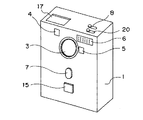
図1〜4は第1実施形態を図示している。図1及び2は、デジタルカメラの斜視図であり、それぞれ、正面側及び背面側から見たものである。その基本構造は、周知であるが、従来の構成と比較して、設定手段としての一対の操作ボタンに関する構成が異なっている。
【0026】
図1,2に示したカメラは、正面視略長方形の6面体のボックス形状であって比較的薄厚のカメラ本体1を有している。その前面には、レンズ3、レリーズボタン7、オートフォーカスユニット部5、ファインダ窓4、フラッシュ6、及び設定手段としてのテレ側操作ボタン15が設けられている。レンズ3はカメラ本体1正面の真中上方に配置されている。その下方には、操作者の手がレンズ3に接触したりレンズ3を覆い隠したりしない程度の距離を離して、略楕円形状のレリーズボタン7が配置されている。正方形をしたテレ側操作ボタン15は、レリーズボタン7の操作の邪魔にならない程度の距離を離してその下方に配置されている。
【0027】
レリーズボタン7及びテレ側操作ボタン15は、図1に示した形状に限定されるものではなく、円形、三角形、長方形、又は星型等の種々の形状にしたり、それらの形状をした操作ボタンの上に凸部や凹部を設けたりすることができる。両操作ボタンを異なった形状にしたり、両操作ボタンに異なった凹凸加工を施すことができる。このような加工を施すことによって、操作者はその指先の感覚でレリーズボタン7とテレ側操作ボタン15とを容易に識別することができる。
【0028】
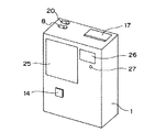
図2において、カメラ本体1の背面の上方には、画面表示部25、ファインダ26、及び合焦表示ランプ27が設けられている。そして、これらの部材の下方であって、前記テレ側操作ボタン15に対して略対向(対応)する位置には、設定手段としてのワイド側操作ボタン14が設けられている。ワイド側操作ボタン14及びテレ側操作ボタン15という一対の操作ボタンにより、不図示のズーム機構をワイド側又はテレ側に駆動させるという相反関係にある機能を設定する設定手段が構成される。この操作ボタン14,15は、記録された画像を呼び出すアクセスボタンとして兼用することができる。記録画像アクセスボタンとして機能している操作ボタン14,15を押すと、記録画像が順送り(UP)又は逆送り(DOWN)されるようになっている。
【0029】
図2に示したワイド側操作ボタン14は、テレ側操作ボタン15と大略同じ正方形の形状であるが、異なった形状であってもよい。そして、ワイド側操作ボタン14及びテレ側操作ボタン15が逆に配置されていてもよいことは言うまでもない。
【0030】
図1,2に示したワイド側操作ボタン14及びテレ側操作ボタン15の占有面積は、これらのボタンをある1面のみに配置する場合より大きくすることができる。また、ワイド側操作ボタン14及びテレ側操作ボタン15は、図1及び2に示した場所に限定されるものではない。上記一対の操作ボタンの好ましい配置場所は、撮影者がカメラ本体1を把持したときに、人間工学的に操作しやすい場所、すなわち、把持している手又は把持していない手のそれぞれの親指と人差指又は中指で操作ボタンを押すことのできる場所である。
【0031】
図1又は2に示すように、カメラ本体1の上面には、情報表示部17、モード切換えスイッチ8、及び(+)(−)方向変更スイッチ20が設けられている。情報表示部17は、例えばLCD等で構成され、各種撮影モード、撮影時のコマ番号、撮影データ、又は日付・時間表示等を表示するためのものである。モード切換えスイッチ8は電源の「ON」「OFF」を切換えるとともに、「記録」モードあるいは「再生」モードに切換えるためのものである。(+)(−)方向変更スイッチ20は、設定手段切換手段であって、ワイド側操作ボタン14及びテレ側操作ボタン15が予め設定された動作と逆方向に動作するように設定変更するためのものである。
【0032】
図3は、図1,2のデジタルカメラのブロック回路図である。
【0033】
システムコントローラ(以下、CPUという)100は、カメラ全体の動作を制御するものである。レンズ3を通して結像される被写体像は固体撮像素子(以下、CCD101という)に取り込まれ、該CCD101から出力される画像信号は、信号処理部102で処理されるようになっている。レンズ3は測距結果に基づいて合焦状態となるようにレンズ駆動部103に駆動制御される。測距部104は、例えば位相差検出方式等を利用して被写体までの距離を求めるものであり、この測距データからレンズ駆動部103によるレンズ3の駆動量が算出される。レンズ駆動部103は、レンズ3を保持するレンズ鏡筒(不図示)の出没、レンズバリア(不図示)の開閉の駆動も行う。測光部105は、被写体の輝度を測定し、その測定データをCPU100に出力する。露出制御部106は、測距及び測光の結果得られたデータに基づいてCPU100が算出した露出時間(シャッタースピード)と絞り値とに従って、カメラの露出制御を行う。表示部107は、上述した情報表示部17及び画像表示部25とそれらの駆動装置とから構成されている。フラッシュ部108は、CPU100からの充電昇圧信号又は発光制御信号によって制御されて、上述したフラッシュ6の発光を行わせる。電源部109は、フラッシュ部108に対して所定の高電圧を印加し、その他の回路部に対して所定レベルの電圧を印加する。記録部111は、撮影によりCCD101に取り込まれた画像データを信号処理部102で所定のフォーマットに画像処理されたデータを記録するためのものであって、半導体メモリ、小型ハードディスク等の各種記録デバイスを用いることができる。
【0034】
カメラ本体1内には、CPU100と、CCD101と、信号処理部102と、レンズ駆動部103と、測距部104と、測光部105と、露出制御部106と、電源109と、フラッシュ部108と、記録部111とが収納されている。CPU100は、上記各部材に電気的に接続されてそれらの間の入出力信号を管理している。その結果、カメラ全体の動作が制御されている。
【0035】
次に、CPU100に接続された、SOFF、SREC、SREP、S1、S2、SUP、SDOWN、S(+)(−)のスイッチ群120について説明する。
【0036】
SOFFは、電源を「OFF」状態にするためのスイッチである。モード切換えスイッチ8を「OFF」位置にすると、電源が「OFF」状態になってカメラが動作しないようになる。
【0037】
SRECは、「記録」モード用のスイッチである。モード切換えスイッチ8を「記録」位置にするとスイッチが「ON」状態になる。「記録」モードでは、カメラでの撮影が可能になり、画像が記録部111に記録される。
【0038】
SREPは、「再生」モード用のスイッチである。モード切換えスイッチ8を「再生」位置にするとスイッチが「ON」状態になる。「再生」モードでは、記録部111に記録された画像を画像表示部25に表示したり、他に接続されたパソコン等に画像データを転送することができる。
【0039】
S1は、撮影準備用のスイッチであり、例えば、レリーズボタン7の1段押し(半押し)に該当する。撮影者がレリーズボタン7を1段押し(半押し)するとスイッチが「ON」状態になって、撮影準備に入るようにCPU100に命令する。
【0040】
S2は、撮影動作用のスイッチであり、例えば、レリーズボタン7の2段押し(全押し)に該当する。撮影者がレリーズボタン7を2段押し(全押し)するとスイッチが「ON」状態になって、撮影動作に入るようにCPU100に命令する。
【0041】
SUPは、相反関係にある機能の設定値を増加させるための操作ボタンである。操作ボタンを押す度に設定値が増加して、例えば、ズーム機構がテレ側に駆動される。
【0042】
SDOWNは、相反関係にある機能の設定値を減少させるための操作ボタンである。操作ボタンを押す度に設定値が減少して、例えば、ズーム機構がワイド側に駆動される。
【0043】
S(+)(−)は、第1スイッチ位置と第2スイッチ位置という2つのスイッチ位置を取り、第1スイッチ位置から第2スイッチ位置に動かすと、上記のSUP及びSDOWNボタンの動作方向を逆にする。
【0044】
次に、図4を用いて、第1実施形態に係るデジタルカメラの操作方法を説明する。
【0045】
図4は、図1のデジタルカメラの操作状態を示す斜視図である。図4(A)は正面側から見たものであり、図4(B)は背面側から見たものである。
【0046】
まず、記録モード時の操作方法について説明する。
【0047】
撮影者がモード切換えスイッチ8を「OFF」位置から「記録」位置にすると、各部分に電気が供給される。そして、CPU100は、各部分が正常に作動しているか否かについての動作チェックを行う。何か不具合があれば、音又は光の警告手段によって撮影者に知らせる。何もなければ、撮影者は、図4及び5に示すように、左手の親指と人差指との間で薄厚のカメラ本体1を挟むようにして、順手という自然な姿勢でカメラ本体1を把持する。したがって、長時間把持していても疲れることが少なく、また、撮影中に手ぶれを起こすことも少ない。この操作姿勢は、左手だけでカメラ本体1を把持しているので、フリーの右手で別の作業を行うことができる。撮影者の左手の人差指、中指、及び親指で、それぞれ、カメラ前面のレリーズボタン7、テレ側操作ボタン15、及びカメラ背面のワイド側操作ボタン14を押すことができる。また、左手の親指と人差指とでテレ側操作ボタン15とワイド側操作ボタン14とを操作するとともに、右手の人差指でレリーズボタン7を操作することもできる。なお、上記し、且つ後述する「右手」操作及び「左手」操作は逆にしてもよいことは言うまでもない。
【0048】
撮影者は、ファインダ26を覗きながら、あるいは画像表示部25に表示された画像を見ながら、中指でテレ側操作ボタン15を、親指でワイド側操作ボタン14を交互に押して、被写体をズーミングして被写体の構図を決める。このとき、操作ボタン14,15が異なった面に配置されているとともに、それらの占有面積が大きくなっているので、撮影者は大面積の操作ボタン14,15を容易に操作することができ、操作ミスが低減される。撮影者は、所望の構図になったと判断すれば、レリーズボタン7を軽く押す(半押しする)。そうすると、撮影準備(測光、測距、露出演算、レンズ3の駆動等)が行われる。撮影者がさらにレリーズボタン7を押す(全押しする)と、実際に撮影が行われて、その撮影画像が記録部111に記録される。なお、撮影時の手ぶれが心配である場合には、空いたもう一方の手をカメラに添えてもよい。また、相反関係にある一対の(+)方向操作ボタン21及び(−)方向操作ボタン22は、ズーム機構のテレ側とワイド側とに駆動させる機能を露出補正機構の露出量を増減させる機能に不図示の機能切換えスイッチにより切換えて、露出補正機構の露出量を(+)側と(−)側とに別個独立に補正することもできる。
【0049】
次に、再生モード時の操作方法について説明する。
【0050】
モード切換えスイッチ8を「再生」位置にすると、記録部111に記録されている撮影画像が呼び出されて画像表示部25に表示される。それとともに、テレ側操作ボタン15とワイド側操作ボタン14は、記録された画像データを呼び出すアクセスボタンに切り替わる。操作者がテレ側操作ボタン15とワイド側操作ボタン14とを交互に押すと、記録画像が画像表示部25上で順送り(UP)又は逆送り(DOWN)、すなわちコマ送りされる。そして、撮影者は順次スクロールされた表示画像の中から見たい画像を選択する。このように、操作ボタン14,15を画像データアクセスボタンとして兼用することによって、トータルのボタン数を減らすことができる。
【0051】
次に、第2実施形態のデジタルカメラについて、図5及び6を参照しながら説明する。
【0052】
図5及び6は、それぞれ、デジタルカメラの正面斜視図、及び背面斜視図である。この実施形態のデジタルカメラでは、大略、第1実施形態と同様に構成されるが、図5及び6に示すように、カメラ本体1の形状と各部材の配置場所とが第1実施形態と異なっている。すなわち、レンズ3のある面を正面とすると、カメラ本体1は、正面視、奥行きがあって幅の狭いボックス形状である。その左側面には、レリーズボタン7と(+)方向操作ボタン21がボディの右側面に、(−)方向操作ボタン22が配置されている。また、相反関係にある一対の(+)方向操作ボタン21及び(−)方向操作ボタン22の機能をその他の機能(例えば、露出補正機構の露出量を増減させる機能、画像表示部25の明暗やコントラストの調整機能)に切換える機能切換えスイッチ19がカメラ本体1の背面に設けられている。
【0053】
図5及び6に示したボタン配置では、例えば、カメラ本体1の幅方向に右手の親指と人差指との間で挟むようにして、カメラ本体1を下方から右手だけで把持しており、フリーの左手で別の作業を行うことができる。このようなボタン配置では、親指が操作ボタン22に、人差指がレリーズボタン7に、中指が操作ボタン21に当接する。あるいは、カメラ本体1の幅方向に右手の親指と人差指との間で挟むようにして、カメラ本体1を右手で把持するとともにカメラ本体1に右手を軽く沿えて、右手親指で操作ボタン22を、右手中指で操作ボタン21をそれぞれ操作するとともに、左手人差指でレリーズボタン7を操作することもできる。
【0054】
図5及び6のボタン配置では、カメラ背面と撮影者の顔との間に撮影者の手が介在しないので、顔をカメラ背面に密着させることができる。また、操作者の手が、レンズ3、オートフォーカスユニット5、及びフラッシュ6といったカメラ正面の光学部材を誤って遮ることがないので、撮影ミスが低減する。カメラの光軸と直交する方向の対向面(すなわち、両側面、及び上面と底面)は、レンズ3、ファインダ4、又はフラッシュ6等の比較的占有面積の大きい光学系部材を有していないので、操作ボタン21,22を大きくすることもできるとともに、操作ボタン21,22の配置場所の自由度が大きくなる。なお、第2実施形態に係るデジタルカメラのその他の操作方法は第1実施形態のものと大略同じであるので省略する。
【0055】
次に、第3実施形態の携帯電話機について、図7を参照しながら説明する。
【0056】
図7は第3実施形態に係る携帯電話機を示し、(A)は正面図、(B)は右側面図、(C)は左側面図である。その基本構造は周知であり、従来の構成と比較して、設定手段としての一対の操作ボタン57b,57cをそれぞれ本体の右側面51e及び左側面51fに設けた構成が異なっている。
【0057】
図7の携帯電話機50は、略長方形の6面体のボックス形状であって比較的薄厚の本体ケース51を有している。その正面51aには、上方から順に、スピーカ53、各種情報を表示する液晶表示部54、操作部55、及びマイク56が設けられている。携帯電話機50の上面にはアンテナ52を備えている。操作部55は、種々の操作を行うためのマトリックス状に配置された各種操作キー群55aを多数備えている。携帯電話機50の小型化に伴って、操作キー群55aの一つ一つのサイズは小さくなっており、各キー間の間隔が狭くなっている。
【0058】
携帯電話機50の本体ケース51の右側面51e及び左側面51fには、一対の操作ボタン57b,57cが設けられている。これらの面には上記以外の操作ボタンが設けられていないために、多くの操作キー群55aの配置された正面51aに上記操作ボタン57b,57cを配置する場合と比較して、設置可能スペースが広くなっている。したがって、一対の操作ボタン57b,57cの占有面積を大きくすることができ、その操作性が向上する。一対の操作ボタン57b,57cは、相反関係にある機能を設定する設定手段として用いられ、例えば、保存されている電話番号を選択するとき、ひらがな、カタカナ、漢字等を入力するとき、又は各種モードの中から所定の機能を選択するときに、液晶表示部54に表示された表示物を正方向あるいは逆方向に順次スクロールするために用いられる。また、スピーカ53やマイク56の音量を大きくしたり、小さくしたりするために用いることもできる。
【0059】
操作者は、例えば、携帯電話機50の正面が操作者の顔の方を向くような状態で携帯電話機50を掌の中に保持しながら使用する。携帯電話機50を左手で把持する場合、右手の指で各種操作キー群55aを操作するとともに、例えば、左手人差指及び左手親指で操作ボタン57b,57cをそれぞれ操作する。一方の操作ボタンを押すと、液晶表示部54に表示されている内容が正方向あるいは逆方向に順次スクロールされ、他方の操作ボタンを押すと、その反対方向に順次スクロールされる。したがって、一対の操作ボタン57b,57cをこのように配置すれば、各キー間の間隔が狭くなっている各種操作キー群55aを一つ一つ操作する場合より、素早く且つ間違い無くボタン操作することができる。そして、携帯電話機50の把持と上記操作ボタン57b,57cの操作とを片手で同時に行うことができ、フリーとなった一方の手で別の作業を行うことができる。
【0060】
なお、本発明は上記実施形態に限定されるものではなく、相反関係にある機能を設定するための一対の操作ボタンが同じ面内に配置されるのでなければ、その他種々の態様で実施可能である。例えば、携帯電話機50の一対の操作ボタン57b,57cは、図7に示した以外の場所に配置することができる。すなわち、上面51gと底面51d、正面51aと背面51bといった対向面に加えて、上面51gと左側面51f、背面51bと左側面51fといった隣接面に設けることができる。また、デジタルカメラにおける相反関係にある機能を設定するための一対の操作ボタン14,15、21,22も、同様に、図1,2、及び図5,6に示した以外の場所、すなわち、上面と底面といった対向面に加えて、上面と正面、背面と左側面といった隣接面に設けることができる。
【0061】
以上説明したように、相反関係にある機能を設定するための一対の操作ボタンを備えた本発明の携帯機器は、設定時の操作ボタンの操作性が改善されている。
【図面の簡単な説明】
【図1】 本発明の第1実施形態に係るデジタルカメラを正面側から見た斜視図である。
【図2】 第1図のデジタルカメラを背面側から見た斜視図である。
【図3】 図1,2のデジタルカメラのブロック回路図である。
【図4】 第1図のデジタルカメラの操作状態を示す斜視図である。(A)は正面側から見たものであり、(B)は背面側から見たものである。
【図5】 本発明の第2実施形態に係るデジタルカメラを正面側から見た斜視図である。
【図6】 第5図のデジタルカメラを背面側から見た斜視図である。
【図7】 本発明の第3実施形態に係る携帯電話機を示す。(A)は正面図、(B)は右側面図、(C)は左側面図である。
【符号の説明】
1 カメラ本体
3 レンズ
4 ファインダ窓
5 オートフォーカスユニット部
6 フラッシュ
7 レリーズボタン
8 モード切換えスイッチ
14 ワイド側操作ボタン
15 テレ側操作ボタン
17 情報表示部
19 機能切換えスイッチ
20 (+)(−)方向変更スイッチ
21 (+)方向操作ボタン
22 (−)方向操作ボタン
25 画像表示部
26 ファインダ
27 合焦表示ランプ
30 手
50 携帯電話機
51 本体ケース
51a 正面
51b 背面
51d 底面
51e 右側面
51f 左側面
51g 上面
52 アンテナ
53 スピーカ
54 液晶表示部
55 操作部
55a 操作ボタン群
56 マイク
57b 操作ボタン
57c 操作ボタン
100 CPU
101 CCD
102 信号処理部
103 レンズ駆動部
104 測距部
105 測光部
106 露出制御部
107 表示部
108 フラッシュ部
109 電源
111 記録部
120 スイッチ群[0001]
BACKGROUND OF THE INVENTION
The present invention can be used for cameras, mobile phones, etc.With camera functionImproved the operability of a pair of operation buttons that have conflicting functions, especially for small portable devicesWith camera functionIt relates to small portable devices.
[0002]
[Prior art]
Various portable devices such as cameras and mobile phones have been reduced in size and weight in order to improve portability. Needless to say, in order to reduce the size of the portable device, it is necessary to reduce the size of the main body of the portable device and the components and members used for the portable device. Various technical studies and improvements have been made in order to miniaturize parts and members of portable devices. However, on the other hand, particularly miniaturized operation buttons such as miniaturized parts and members tend to be difficult to handle.
[0003]
The portable device is provided with various operation buttons in order to perform various functions. In an almost box-shaped portable device, 1) all operation buttons are arranged on one operation surface, and 2) main related operation buttons are arranged on one operation surface, while related There are cases where operation buttons with low performance are distributed on other operation surfaces. In the former case, the smaller the portable device is, the smaller the area occupied by each operation button, so the operability becomes worse. Further, in the latter case, the operability of the operation buttons is not deteriorated even if the former is not as much. In any case, deterioration in operability due to downsizing is caused by a pair of operation buttons whose functions are in a contradictory relationship (for example, a function for moving the operation part back and forth and rotating left and right, a function for increasing and decreasing volume, and a function for increasing and decreasing illuminance on the display part) This is conspicuous in the function or operation buttons for performing various settings such as a scroll function for the front / rear / left / right of the display portion.
[0004]
For example, in the case of a camera, as the setting change operation button, the zoom switching button for switching the zoom mechanism to the tele / wide side, or the exposureincreaseside/DecreaseIt has an exposure compensation button that compensates for the side. There is a type in which a pair of operation buttons having a contradictory relationship between these functions are adjacently arranged on one operation surface, and the setting is changed by operating one of the buttons. There is also a type in which the setting change operation button is a rotary switch. In any case, if the setting change operation button is downsized, the setting change operation button becomes too small with respect to the size of the operator's finger. There is a problem that is bad. In particular, when a pair of setting change buttons whose functions are in a contradictory relationship are arranged adjacent to each other on one operation surface, there is a high possibility that a button operation will be wrong, and in that case, the operation opposite to the desired operation will be performed. There's a problem.
[0005]
As described above, the conventional portable device is only focused on reducing its size, and there is a tendency that the operability of the setting change operation button is not sufficiently considered.
[0006]
[Problems to be solved by the invention]
Therefore, a technical problem to be solved by the present invention is a pair of operation buttons for setting functions having a conflicting relationship.With camera function withIn mobile devices,A pair of operation buttonsIt is to improve the operability.
[0007]
[Means for solving the problems and actions / effects]
In order to solve the above technical problem, according to the present invention, the following configuration is provided.With camera functionA portable device is provided.
[0008]
The mobile device with a camera function includes a pair of operation buttons for setting functions having a contradictory relationship and a zoom mechanism, and the pair of operation buttons are respectively disposed on opposing surfaces of the mobile device body. The operation button is operated to drive the zoom mechanism to the tele side and the wide side..
[0009]
According to the above configuration, with the operator holding the portable device main body, the pair of operation buttons disposed on the opposite surface of the portable device are held with two fingers.Driving the zoom mechanism to the tele and wide sidesOperation errors can be reduced. In addition, since the setting operation can be sensed with two fingertips, the operator can feel assured that the operation has been performed without fail.
[0010]
Also, by arranging one operation button on a certain surface and arranging the other operation button on the opposite surface, one operation button is occupied as compared with a case where a pair of operation buttons are disposed on one surface. The area can be increased and the operability is improved.
[0011]
The two fingers that operate the operation buttons are usually the thumb and the index or middle finger. The thumb and index finger or middle finger may be the same hand or different hands. Needless to say, the two fingers that operate the operation buttons may be other than the thumb, index finger, or middle finger.
[0012]
The mobile device with a camera function has a pair of operation buttons for setting functions having a contradictory relationship, and an exposure correction mechanism, and the pair of operation buttons are respectively disposed on opposing surfaces of the mobile device body, A pair of operation buttons corrects the exposure compensation mechanism to increase or decrease the exposure amount. To be operated.
[0013]
According to the above configuration, the exposure amount of the exposure correction mechanism provided in the small camera is reduced.increaseSide andDecreaseCorrection can be performed independently for each side, and operation errors are reduced.
[0014]
The mobile device with a digital camera function has a pair of operation buttons for setting functions having a contradictory relationship, and an image display means for displaying a photographed image, and the pair of operation buttons are respectively provided on opposite surfaces of the mobile device body. The pair of operation buttons are operated to increase or decrease the frame number of the captured image.
[0015]
According to the above configuration, the frame number of the captured image displayed on the image display means provided in the digital camera can be increased / decreased independently, and operation errors are reduced.
[0016]
Preferably, the portable device has a size that can be held between the thumb and the index finger.
[0017]
According to the above configuration, with the operator holding the portable device main body between the thumb and index finger of one hand, the pair of operation buttons arranged on the opposite surface of the portable device are connected to the thumb and index finger of one hand. Alternatively, it can be operated independently with the middle finger. That is, the operator can simultaneously hold the device body and operate the buttons with one hand, and can perform another operation with the other hand that has become free.
[0018]
Preferably, the pair of operation buttons are respectively provided on the subject side surface and the photographer side surface of the camera.
[0019]
According to the above-described configuration, the photographer can hold the camera in a natural posture that is good and can operate a pair of buttons. Therefore, it is less likely to get tired even if it is held for a long time, and it is less likely to cause camera shake during shooting.
[0020]
Preferably, the pair of operation buttons are respectively provided on opposing surfaces in a direction orthogonal to the photographing optical axis of the camera.
[0021]
According to the above configuration, since the photographer's hand is not interposed between the back of the camera and the photographer's face, the photographer's face can be brought into close contact with the back of the camera, and the camera's viewfinder can be looked into. You can shoot while standing. In addition, a photographer's hand does not accidentally cover a member exposed in front of the camera, such as a lens unit, a distance measuring unit, a photometric unit, or a flash. The opposing surface in the direction perpendicular to the optical axis of the camera's imaging optical axis does not have an optical system member with a relatively large area, such as a lens unit, a finder, or a flash. Increases the degree of freedom of placement.
[0022]
Preferably, the apparatus has setting means switching means capable of reversing the setting of functions having a reciprocal relationship.
[0023]
According to the above configuration, if the operator is not familiar with the preset operation method of the setting means, the setting means switching means can reverse the setting so that the operation can be easily performed.
[0024]
DETAILED DESCRIPTION OF THE INVENTION
The digital camera according to each embodiment of the present invention will be specifically described below.
[0025]
1 to 4 illustrate a first embodiment. 1 and 2 are perspective views of the digital camera, as seen from the front side and the back side, respectively. The basic structure is well known, but the configuration relating to the pair of operation buttons as setting means is different from the conventional configuration.
[0026]
The camera shown in FIGS. 1 and 2 has a
[0027]
The
[0028]
In FIG. 2, a
[0029]
The wide-
[0030]
The area occupied by the wide-
[0031]
As shown in FIG. 1 or 2, an
[0032]
FIG. 3 is a block circuit diagram of the digital camera of FIGS.
[0033]
A system controller (hereinafter referred to as CPU) 100 controls the operation of the entire camera. A subject image formed through the
[0034]
In the
[0035]
Next, the switch group 120 of SOFF, SREC, SREP, S1, S2, SUP, SDOWN, and S (+) (−) connected to the
[0036]
SOFF is a switch for turning off the power. When the
[0037]
SREC is a switch for “recording” mode. When the
[0038]
SREP is a switch for the “playback” mode. When the
[0039]
S1 is a switch for shooting preparation, and corresponds to, for example, one-step pressing (half-pressing) of the
[0040]
S2 is a switch for photographing operation, and corresponds to, for example, a two-step pressing (full pressing) of the
[0041]
SUP is an operation button for increasing the set value of a function having a conflicting relationship. Each time the operation button is pressed, the set value increases. For example, the zoom mechanism is driven to the tele side.
[0042]
SDOWN is an operation button for decreasing the set value of the function having the contradictory relationship. Each time the operation button is pressed, the set value decreases, and for example, the zoom mechanism is driven to the wide side.
[0043]
S (+) (-) takes two switch positions, the first switch position and the second switch position, and reverses the operating direction of the SUP and SDOWN buttons when moved from the first switch position to the second switch position. To.
[0044]
Next, the operation method of the digital camera according to the first embodiment will be described with reference to FIG.
[0045]
FIG. 4 is a perspective view showing an operation state of the digital camera of FIG. FIG. 4A is viewed from the front side, and FIG. 4B is viewed from the back side.
[0046]
First, an operation method in the recording mode will be described.
[0047]
When the photographer changes the
[0048]
The photographer zooms in on the subject by alternately pressing the tele-
[0049]
Next, an operation method in the playback mode will be described.
[0050]
When the
[0051]
Next, a digital camera according to a second embodiment will be described with reference to FIGS.
[0052]
5 and 6 are a front perspective view and a rear perspective view of the digital camera, respectively. The digital camera of this embodiment is generally configured in the same manner as in the first embodiment, but as shown in FIGS. 5 and 6, the shape of the
[0053]
In the button arrangement shown in FIGS. 5 and 6, for example, the
[0054]
5 and 6, since the photographer's hand is not interposed between the camera back surface and the photographer's face, the face can be brought into close contact with the camera back surface. In addition, since the operator's hand does not accidentally block the optical members in front of the camera such as the
[0055]
Next, a mobile phone according to a third embodiment will be described with reference to FIG.
[0056]
7A and 7B show a mobile phone according to a third embodiment. FIG. 7A is a front view, FIG. 7B is a right side view, and FIG. 7C is a left side view. The basic structure is well known, and differs from the conventional configuration in that a pair of
[0057]
The
[0058]
A pair of
[0059]
For example, the operator uses the
[0060]
Note that the present invention is not limited to the above-described embodiment, and can be implemented in various other forms unless a pair of operation buttons for setting functions having a contradictory relationship are arranged in the same plane. is there. For example, the pair of
[0061]
As described above, the operability of the operation buttons at the time of setting is improved in the portable device of the present invention provided with a pair of operation buttons for setting the functions having the contradictory relationship.
[Brief description of the drawings]
FIG. 1 is a perspective view of a digital camera according to a first embodiment of the present invention as viewed from the front side.
FIG. 2 is a perspective view of the digital camera of FIG. 1 as viewed from the back side.
FIG. 3 is a block circuit diagram of the digital camera of FIGS.
4 is a perspective view showing an operation state of the digital camera of FIG. 1. FIG. (A) is viewed from the front side, and (B) is viewed from the back side.
FIG. 5 is a perspective view of a digital camera according to a second embodiment of the present invention as viewed from the front side.
6 is a perspective view of the digital camera of FIG. 5 as viewed from the back side.
FIG. 7 shows a mobile phone according to a third embodiment of the present invention. (A) is a front view, (B) is a right side view, and (C) is a left side view.
[Explanation of symbols]
1 Camera body
3 Lens
4 Finder window
5 Autofocus unit
6 Flash
7 Release button
8 Mode switch
14 Wide side operation buttons
15 Tele side operation button
17 Information display section
19 Function selector switch
20 (+) (-) direction change switch
21 (+) direction operation button
22 (-) Direction operation button
25 Image display
26 Finder
27 Focus indicator lamp
30 hands
50 Mobile phone
51 Main unit case
51a front
51b back
51d Bottom
51e right side
51f Left side
51g top surface
52 Antenna
53 Speaker
54 Liquid crystal display
55 Operation unit
55a Operation buttons
56 microphone
57b Operation buttons
57c Operation button
100 CPU
101 CCD
102 Signal processor
103 Lens drive unit
104 Ranging section
105 Metering unit
106 Exposure control unit
107 Display
108 Flash unit
109 power supply
111 Recording unit
120 switches
Claims (7)
相反関係にある機能を設定する一対の操作ボタンと、ズーム機構と、を有し、A pair of operation buttons for setting functions that are in a reciprocal relationship, and a zoom mechanism;
前記一対の操作ボタンが携帯機器本体の対向面にそれぞれ配置されており、The pair of operation buttons are respectively disposed on opposite surfaces of the mobile device body,
前記一対の操作ボタンは、前記ズーム機構をテレ側とワイド側とに駆動するために操作されることを特徴とする、カメラ機能付き携帯機器。The pair of operation buttons are operated to drive the zoom mechanism to a tele side and a wide side, and a mobile device with a camera function.
相反関係にある機能を設定する一対の操作ボタンと、露出補正機構と、を有し、A pair of operation buttons for setting the functions that are in conflict with each other, and an exposure correction mechanism;
前記一対の操作ボタンが携帯機器本体の対向面にそれぞれ配置されており、The pair of operation buttons are respectively disposed on opposite surfaces of the mobile device body,
前記一対の操作ボタンは、前記露出補正機構を露出量を増加側と減少側とに補正するために操作されることを特徴とする、カメラ機能付き携帯機器。The pair of operation buttons are operated to correct the exposure amount of the exposure correction mechanism to an increase side and a decrease side, and a portable device with a camera function.
相反関係にある機能を設定する一対の操作ボタンと、撮影画像を表示する画像表示手段と、を有し、A pair of operation buttons for setting a function in a conflict relationship, and an image display means for displaying a captured image;
前記一対の操作ボタンが携帯機器本体の対向面にそれぞれ配置されており、The pair of operation buttons are respectively disposed on opposite surfaces of the mobile device body,
前記一対の操作ボタンは、前記撮影画像のコマ番号を増減するために操作されることを特徴とする、デジタルカメラ機能付き携帯機器。The portable device with a digital camera function, wherein the pair of operation buttons are operated to increase or decrease the frame number of the captured image.
Priority Applications (2)
| Application Number | Priority Date | Filing Date | Title |
|---|---|---|---|
| JP36435199A JP3777928B2 (en) | 1999-12-22 | 1999-12-22 | Mobile device with camera function |
| US09/741,155 US6415106B2 (en) | 1999-12-22 | 2000-12-21 | Portable apparatus |
Applications Claiming Priority (1)
| Application Number | Priority Date | Filing Date | Title |
|---|---|---|---|
| JP36435199A JP3777928B2 (en) | 1999-12-22 | 1999-12-22 | Mobile device with camera function |
Publications (2)
| Publication Number | Publication Date |
|---|---|
| JP2001184970A JP2001184970A (en) | 2001-07-06 |
| JP3777928B2 true JP3777928B2 (en) | 2006-05-24 |
Family
ID=18481607
Family Applications (1)
| Application Number | Title | Priority Date | Filing Date |
|---|---|---|---|
| JP36435199A Expired - Fee Related JP3777928B2 (en) | 1999-12-22 | 1999-12-22 | Mobile device with camera function |
Country Status (2)
| Country | Link |
|---|---|
| US (1) | US6415106B2 (en) |
| JP (1) | JP3777928B2 (en) |
Families Citing this family (17)
| Publication number | Priority date | Publication date | Assignee | Title |
|---|---|---|---|---|
| JP2001305634A (en) * | 2000-04-24 | 2001-11-02 | Ricoh Co Ltd | Camera |
| US20030089777A1 (en) * | 2001-11-15 | 2003-05-15 | Rajasekharan Ajit V. | Method and system for authoring and playback of audio coincident with label detection |
| JP2004297751A (en) * | 2003-02-07 | 2004-10-21 | Sharp Corp | Focusing state display device and focusing state display method |
| US20050275729A1 (en) * | 2003-03-13 | 2005-12-15 | Logitech Europe S.A. | User interface for image processing device |
| JP2005267000A (en) | 2004-03-17 | 2005-09-29 | Sony Corp | Electronic device and function assignment method |
| KR100604320B1 (en) * | 2004-08-19 | 2006-07-24 | 삼성테크윈 주식회사 | Method of controlling digital photographing apparatus for efficient replay operation |
| KR100651807B1 (en) * | 2004-08-25 | 2006-12-01 | 삼성테크윈 주식회사 | Method of controlling digital photographing apparatus for efficient setting operation, and digital photographing apparatus adopting the method |
| KR101086403B1 (en) * | 2004-09-10 | 2011-11-25 | 삼성전자주식회사 | Method for controlling digital photographing apparatus, and digital photographing apparatus adopting the method |
| US7199832B2 (en) * | 2004-10-01 | 2007-04-03 | Daniel Oran | Portable photographic device and grip with integrated controls for single handed use |
| JP4411193B2 (en) | 2004-12-09 | 2010-02-10 | 富士フイルム株式会社 | Imaging device with display and image display device |
| KR100716816B1 (en) * | 2004-12-20 | 2007-05-09 | 주식회사 팬택 | Mobile telecommunications terminal and method for controlling a photographing process of the same |
| US20070173314A1 (en) * | 2006-01-26 | 2007-07-26 | Daka Studio Inc. | Sudoku game device with dual control button |
| JP5506589B2 (en) * | 2010-08-02 | 2014-05-28 | キヤノン株式会社 | Imaging apparatus, control method therefor, program, and recording medium |
| USD770553S1 (en) * | 2014-11-19 | 2016-11-01 | Fire Cam, LLC | Video camera |
| USD860292S1 (en) * | 2015-04-29 | 2019-09-17 | Sharingbox SA | Camera |
| USD849104S1 (en) * | 2017-10-26 | 2019-05-21 | Photobooth Supply Co. | Photo booth |
| USD890832S1 (en) * | 2018-05-03 | 2020-07-21 | Marlon Andres | Mobile photo device |
Family Cites Families (7)
| Publication number | Priority date | Publication date | Assignee | Title |
|---|---|---|---|---|
| JPH07119868B2 (en) * | 1985-06-20 | 1995-12-20 | オリンパス光学工業株式会社 | Interchangeable lens distance information output device |
| US5128704A (en) * | 1988-10-04 | 1992-07-07 | Canon Kabushiki Kaisha | Camera having information or function setting device |
| US5291236A (en) * | 1989-02-10 | 1994-03-01 | Canon Kabushiki Kaisha | Camera |
| KR0143812B1 (en) | 1995-08-31 | 1998-08-01 | 김광호 | Cordless telephone for mouse |
| US6118480A (en) | 1997-05-05 | 2000-09-12 | Flashpoint Technology, Inc. | Method and apparatus for integrating a digital camera user interface across multiple operating modes |
| JP3938623B2 (en) | 1997-12-04 | 2007-06-27 | オリンパス株式会社 | camera |
| US6067358A (en) | 1998-03-25 | 2000-05-23 | Grant; Alan H. | Ergonomic cellular phone |
-
1999
- 1999-12-22 JP JP36435199A patent/JP3777928B2/en not_active Expired - Fee Related
-
2000
- 2000-12-21 US US09/741,155 patent/US6415106B2/en not_active Expired - Lifetime
Also Published As
| Publication number | Publication date |
|---|---|
| US6415106B2 (en) | 2002-07-02 |
| JP2001184970A (en) | 2001-07-06 |
| US20010014214A1 (en) | 2001-08-16 |
Similar Documents
| Publication | Publication Date | Title |
|---|---|---|
| JP3777928B2 (en) | Mobile device with camera function | |
| US9451134B2 (en) | Display device | |
| US20100166404A1 (en) | Device and Method Using a Touch-Detecting Surface | |
| JP2004080776A (en) | Mobile information processing apparatus | |
| JPH11289484A (en) | Camera with monitor | |
| US20060017694A1 (en) | Information processing device and information processing method | |
| JP2000101879A (en) | Image pickup device | |
| JP5113237B2 (en) | Electronic camera | |
| JP2004254185A (en) | Digital camera | |
| JP5072042B2 (en) | Imaging device with projection display function and portable imaging projector | |
| JP2006113174A (en) | Digital camera | |
| JP4481673B2 (en) | Digital camera | |
| JP2008298819A (en) | Portable electronic equipment, camera and cellular phone | |
| JP4581780B2 (en) | Display device with touch panel | |
| JP4892125B2 (en) | Electronic still camera | |
| JP4774118B2 (en) | Electronic camera | |
| JP2010134351A (en) | Digital camera | |
| JP2001325056A (en) | Input unit and image pickup device | |
| JP2006303714A (en) | Mobile image display apparatus and camera including image display apparatus | |
| JP4507278B2 (en) | Display device with switch panel | |
| JP2003287794A (en) | Camera | |
| JP2004170570A (en) | Camera | |
| JP6470871B2 (en) | Setting device and camera | |
| JPH1023302A (en) | Image pickup device | |
| JPH10336502A (en) | Electronic camera |
Legal Events
| Date | Code | Title | Description |
|---|---|---|---|
| A711 | Notification of change in applicant |
Free format text: JAPANESE INTERMEDIATE CODE: A712 Effective date: 20050615 |
|
| A521 | Request for written amendment filed |
Free format text: JAPANESE INTERMEDIATE CODE: A821 Effective date: 20050713 |
|
| RD02 | Notification of acceptance of power of attorney |
Free format text: JAPANESE INTERMEDIATE CODE: A7422 Effective date: 20050713 |
|
| A977 | Report on retrieval |
Free format text: JAPANESE INTERMEDIATE CODE: A971007 Effective date: 20050819 |
|
| A131 | Notification of reasons for refusal |
Free format text: JAPANESE INTERMEDIATE CODE: A131 Effective date: 20050906 |
|
| A521 | Request for written amendment filed |
Free format text: JAPANESE INTERMEDIATE CODE: A523 Effective date: 20051021 |
|
| TRDD | Decision of grant or rejection written | ||
| A01 | Written decision to grant a patent or to grant a registration (utility model) |
Free format text: JAPANESE INTERMEDIATE CODE: A01 Effective date: 20060207 |
|
| A61 | First payment of annual fees (during grant procedure) |
Free format text: JAPANESE INTERMEDIATE CODE: A61 Effective date: 20060220 |
|
| R150 | Certificate of patent or registration of utility model |
Free format text: JAPANESE INTERMEDIATE CODE: R150 |
|
| FPAY | Renewal fee payment (event date is renewal date of database) |
Free format text: PAYMENT UNTIL: 20100310 Year of fee payment: 4 |
|
| FPAY | Renewal fee payment (event date is renewal date of database) |
Free format text: PAYMENT UNTIL: 20100310 Year of fee payment: 4 |
|
| FPAY | Renewal fee payment (event date is renewal date of database) |
Free format text: PAYMENT UNTIL: 20110310 Year of fee payment: 5 |
|
| FPAY | Renewal fee payment (event date is renewal date of database) |
Free format text: PAYMENT UNTIL: 20110310 Year of fee payment: 5 |
|
| FPAY | Renewal fee payment (event date is renewal date of database) |
Free format text: PAYMENT UNTIL: 20120310 Year of fee payment: 6 |
|
| FPAY | Renewal fee payment (event date is renewal date of database) |
Free format text: PAYMENT UNTIL: 20130310 Year of fee payment: 7 |
|
| FPAY | Renewal fee payment (event date is renewal date of database) |
Free format text: PAYMENT UNTIL: 20130310 Year of fee payment: 7 |
|
| FPAY | Renewal fee payment (event date is renewal date of database) |
Free format text: PAYMENT UNTIL: 20140310 Year of fee payment: 8 |
|
| R250 | Receipt of annual fees |
Free format text: JAPANESE INTERMEDIATE CODE: R250 |
|
| LAPS | Cancellation because of no payment of annual fees |