JP3777871B2 - Injector drive device - Google Patents
Injector drive device Download PDFInfo
- Publication number
- JP3777871B2 JP3777871B2 JP13592399A JP13592399A JP3777871B2 JP 3777871 B2 JP3777871 B2 JP 3777871B2 JP 13592399 A JP13592399 A JP 13592399A JP 13592399 A JP13592399 A JP 13592399A JP 3777871 B2 JP3777871 B2 JP 3777871B2
- Authority
- JP
- Japan
- Prior art keywords
- fuel
- valve
- electromagnetic solenoid
- injector
- pressure
- Prior art date
- Legal status (The legal status is an assumption and is not a legal conclusion. Google has not performed a legal analysis and makes no representation as to the accuracy of the status listed.)
- Expired - Fee Related
Links
Images


Description
【0001】
【発明の属する技術分野】
本発明は、コモンレール式ディーゼルエンジン等に適用されるインジェクタ駆動装置に関するものである。
【0002】
【従来の技術】
直噴式ディーゼルエンジンや直噴式ガソリンエンジン等においては、高圧噴射が可能で噴霧微粒化に有利なコモンレール式燃料噴射装置が用いられる。特に噴霧微粒化には噴孔径縮小という方法もあるが、加工上限界があるので噴射圧は益々高まる傾向にある。こういった意味でコモンレール方式は近年さらに注目視されている。
【0003】
一般にコモンレール式燃料噴射装置では高圧ポンプで加圧された燃料をコモンレール(蓄圧室)に一旦貯留し、これをインジェクタから所定タイミングで所定量ずつ、各気筒内に噴射するようになっている。
【0004】
インジェクタは、その下端ないし先端に設けられた噴孔を、ニードル(針弁)の昇降により開閉し、燃料噴射を実行する。特にインジェクタのうち圧力バランス式と称されるものがある。これはニードル後端側の圧力制御室(バランスチャンバ)の圧力を制御することによりニードルを昇降させるものである。
【0005】
【発明が解決しようとする課題】
ところで、ディーゼル燃焼の場合、燃料噴射開始から所定の着火遅れ期間を経て初期燃焼が開始する。この初期燃焼の際に急激な燃焼が行われると、筒内温度が急上昇し、NOx 発生量が増大する。そこで初期燃焼を比較的緩慢に行いつつ後の主燃焼に繋げたいという要請がある。
【0006】
通常、コモンレール式インジェクタでは、ニードル上昇と同時にインジェクタ内に待機していた加圧燃料が一気に大量に噴射される傾向にある。これだと初期噴射率が増大し、初期燃焼が急激となって先の要請に合わない。そこで、初期噴射率を抑制し得る圧力バランス式インジェクタが種々提案されている(特開平11-22584号公報等)。
【0007】
一般に、圧力バランス式インジェクタでは、高圧燃料が常時供給される圧力制御室を備え、この室内燃料を選択的にリークさせることで室内圧を低圧にし、ニードル上昇を開始させる。そしてこの燃料リークの制御は電磁弁で行われる。電磁弁は圧力制御室のリーク穴を開閉する開閉弁と、開閉弁を閉弁方向に付勢する弁バネと、当該バネ力に抗じて開閉弁を開弁方向に駆動する電磁ソレノイドとからなる。
【0008】
従来、開閉弁を二段階で開放し、初期燃料リーク速度を遅くしてニードルの二段階上昇を行わせ、初期噴射率抑制を図ったインジェクタがある。
【0009】
しかし、これは弁バネを二つ設ける手法を採っていた。これだと当然弁バネの数が増え、部品点数増加によるコスト上昇を招く。また互いの弁バネのバネ定数の差に基づいて噴射特性が決定されるため、弁バネのへたり等、経時変化により噴射特性に影響が及ぶ可能性がある。
【0010】
【課題を解決するための手段】
本発明に係るインジェクタ駆動装置は、エンジン運転状態に応じて燃料の初期噴射率を低初期噴射率と高初期噴射率とに切り換えるようにしたインジェクタ駆動装置であって、印加電圧に応じてインジェクタを開作動するための電磁ソレノイドと、該電磁ソレノイドに接続され、その電磁ソレノイドにバッテリ電圧を印加するためのバッテリと、上記電磁ソレノイドに接続され、その電磁ソレノイドに上記バッテリ電圧より高いコンデンサ電圧を印加するためのコンデンサと、上記初期噴射率を低初期噴射率に切り換える際には、上記バッテリを上記電磁ソレノイドに導通し、一方上記初期噴射率を高初期噴射率に切り換える際には、上記コンデンサを上記電磁ソレノイドに導通するドライバユニットとを備えたものである。
【0011】
【発明の実施の形態】
以下、本発明の一実施形態を添付図面に基いて説明する。
【0012】
図4は本発明が適用される直噴ディーゼルエンジンのコモンレール式燃料噴射装置を示す。エンジンの各気筒毎にインジェクタ1が設けられ、各インジェクタ1には、高圧管73を通じ、コモンレール72に貯留されたコモンレール圧(数10〜数100MPa)の高圧燃料が常時供給されている。コモンレール72への燃料圧送は主に高圧ポンプ78によって行われる。即ち、燃料タンク74の常圧程度の燃料が燃料フィルタ75を通じてフィードポンプ76に吸引され、これにより燃料がフィード管77を通じて高圧ポンプ78に送られる。ここで燃料が高圧に加圧され、高圧管79を通じてコモンレール72に送られる。インジェクタ1は前述の圧力バランス式コモンレールインジェクタである。よってインジェクタ1内の圧力制御室からリークされた燃料がリーク管81を通じて燃料タンク74に戻される。また高圧ポンプ78は出口圧を制御するための圧力制御部を有しているため、高圧ポンプ78から排出された燃料が戻り管80を通じて燃料タンク74に戻されるようになっている。
【0013】
インジェクタ1の燃料噴射量と噴射時期とが電子制御装置(以下ECMという)82及びドライバユニット84によって制御される。ECM82は、図示しない各センサ類からエンジン運転状態(回転数、負荷等)を検知し、これに見合った目標噴射量及び目標噴射時期を決定すると共に、これらに相当する小電圧パルスをドライバユニット84に送出する。これを受けてドライバユニット84は、比較的大きな駆動電圧を電磁ソレノイド85に印加し、インジェクタ1を開作動させる。また、ECM82は、エンジン運転状態に応じてコモンレール圧をフィードバック制御する。即ち、コモンレール2にコモンレール圧センサ83が設けられ、この値に基づき高圧ポンプ78の出口圧を制御する。
【0014】
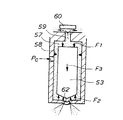
次に、ここで用いる圧力バランス式コモンレールインジェクタの作動原理を説明する。図5に示すように、インジェクタ1においては、ノズルボディ51内の穴52にニードル53が昇降自在に収容され、これら穴52とニードル53との隙間を通じて噴孔55にコモンレール圧Pcの高圧燃料が導かれる。燃料入口は56で示される。ニードル53後端側に圧力制御室57が設けられ、これは絞り58を境に噴孔55側の燃料通路61と連通状態で仕切られる。圧力制御室57にはリーク穴59が設けられ、リーク穴59の出口が開閉弁60により開閉される。開閉弁60は電磁ソレノイドと弁バネとの協同作用により昇降駆動される。ニードル53はバネ定数の比較的低いバネ(図示せず)でインジェクタ閉弁方向(下向き)に常時付勢されている。
【0015】
図5に示す噴孔閉鎖状態では、リーク穴59が閉じられ、ニードル53は下方のシート部62に着座している。このときニードル53は下向きの燃圧力F1 と下向きのバネ力F3 と上向きの燃圧力F2 とを受けている。下向きを正とするとニードル53が受ける力FはF1 +F3 −F2 である。ここでコモンレール圧をPc、ニードル断面積をA1 、シート部断面積をA2 とすると、
F1 =Pc×A1
F2 =Pc×(A1 −A2 )
よってF=F1 +F3 −F2 =F3 +Pc×A2 となり、一旦噴孔55が閉まってしまえば仮にバネ力F3 がなくても理論的には閉弁が維持される。ただしバネ力F3 があることでニードル53の着座即ち閉弁は完全となる。
【0016】
A2 は微小であり、Pc×A2 も小さい値である。よってバネ力F3 がないとすれば、ニードル53は燃圧でバランスされたいわば浮いた状態に近い。このバランス状態を崩すことによりニードル53が上昇し燃料噴射が実行されるのである。
【0017】
この燃料噴射実行中ないし噴孔開放状態を示したのが図6である。このときリーク穴59が開かれ、圧力制御室57の燃料がリークされる。絞り58があるため圧力制御室57への燃料供給がリークに追いつかず、圧力制御室57の圧力がコモンレール圧Pcより低圧のPlとなる。これによって圧力バランスが崩れ、ニードル53が上昇し燃料噴射が実行される。この実行中は
F1 =Pl×A1
F2 =Pc×A1
F=F1 +F3 −F2 =(Pl−Pc)×A1 +F3
となり、F<0つまりニードル53は上昇される。
【0018】
この状態からリーク穴59が閉じられると圧力制御室57がコモンレール圧Pcに復帰する。するとニードル53は燃圧によっては完全バランスされているが、バネ力F3 を受けているためこれによって下降する。つまりバネ力F3 は主にニードル下降に必要となる。ただしその値自体は小さな値で済むのでバネ定数の低いバネが使用できる。こうしてFが負の値から正の値に転じた時点でニードル53の下降が開始し、ニードル53がシート部62に着座すれば燃料噴射が停止する。
【0019】
かかる原理に基づくインジェクタの具体的態様を図3に示す。インジェクタ1は、そのノズルボディ3内の穴3aにニードル4を昇降自在に収容させる。またインジェクタ1は、先の高圧管73に通ずる燃料入口2からコモンレール圧の燃料を導入し、その高圧燃料を穴3aとニードル4との隙間を通じて下方の噴孔16に導く。穴3a内では前述の如くニードル4が高圧燃料に浸漬され、いわば浮いた状態となっている。ニードル4はバネ8によって下方即ちインジェクタ閉弁方向に常時付勢される。バネ8はコイルスプリングからなり、ニードル4に固定されたバネ受け5と、穴3aの段差部6下面との間に圧縮状態で挟まれる。
【0020】
ニードル4の頂面9が小容積の圧力制御室10に臨まされ、圧力制御室10には燃料入口2から分岐された入口通路7と絞り通路14とを通じて高圧燃料が常時導かれる。頂面9付近ではニードル4と穴3aの隙間がほとんどなく、その隙間を通じた下方から圧力制御室10への燃料供給は行われない。そこで別系統の入口通路7及び絞り通路14を設け、ここから圧力制御室10に燃料供給を行うようにしたものである。よってここでは絞り通路14が前記絞り58をなす。
【0021】
圧力制御室10の燃料が開閉弁11の昇降によりリーク穴12から選択的にリークされる。開閉弁11は弁バネ11aにより常時下方(閉弁方向)に付勢され、通常はリーク穴12を閉じている。これにより圧力制御室10がコモンレール圧となり、ニードル4がシート部に着座して噴孔16を閉じ、噴射停止状態となる。電磁ソレノイド85が励磁されると開閉弁11が弁バネ11aのバネ力に抗じて上方(開弁方向)に駆動され、リーク穴12を開く。これにより圧力制御室10の燃料がリークし、圧力制御室10が低圧となり、ニードル4が上昇してシート部から離れ、噴孔16が開き、燃料噴射が実行される。なおリーク燃料はリーク通路17を通じて先のリーク管81に至る。
【0022】
これら開閉弁11、弁バネ11a及び電磁ソレノイド85によりインジェクタ1の電磁弁20が構成される。開閉弁11は所謂フラットシートバルブで、円形平板状に形成されると共に電磁弁20のアーマチュアを兼ねる。開閉弁11の上方に微小な隙間があり、開閉弁11が微小ストローク( 0.1〜0.2mm 程度)だけ昇降できるようになっている。リーク穴12は、穴3aに挿入固定された弁座部材21の中心に穿設される。弁座部材21は、リーク穴出口を区画する中心突起22と、外周端縁部に位置する外周突起23とを有する。これら突起22,23の上面が同一高さ位置で同一平面をなし、フラットに形成される。これにより開閉弁11が突起22,23の上面に均一に着座する。こうすることによって開閉弁11が中心突起22のみに押しつけられず、開閉弁11の湾曲、凹み等が防止される。
【0023】
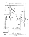
次に、図1を用いて本発明に係るインジェクタ駆動装置を説明する。図示するように、かかる駆動装置はECM82、ドライバユニット84、電磁ソレノイド85及びバッテリ25を備えて構成される。電磁ソレノイド85にはバッテリ25で発生するバッテリ電圧VB (ここでは12V )がダイオード26を介して印加供給されるようになっている。また電磁ソレノイド85には、選択的に、コンデンサ27に蓄電された電圧VC (ここでは100V)がトランジスタ28を介して印加供給されるようになっている。VB <VC である。
【0024】
電磁ソレノイド85の低電位側(アース側)にもトランジスタ29が設けられる。これは電磁ソレノイド85に対するメインスイッチとなり、ECM82からコマンドパルスが送られたときのみONとなる。
【0025】
バッテリ25とコンデンサ27との間にコンデンサ充電回路30が設けられる。これはコイルLと抵抗RからなるLR回路31と、LR回路31の低電位側に設けられたスイッチとしてのトランジスタ32と、これからコンデンサ27に至る回路の途中に設けられたダイオード33と、トランジスタ32のON/OFF信号を発生するクロック34とからなる。クロック34は、ECM82から常時発生する小電圧(ここでは5V程度)を与えられて極めて短い時間間隔毎に電圧パルスを発生する。これとLR回路31との協同作用によって、コンデンサ27には高電圧(ここでは100V以上)によるチョッピング電流が与えられ、コンデンサ27は充電される。
【0026】
一方、ECM82とトランジスタ28との間にAND素子35が設けられ、AND素子35の出力に応じてトランジスタ28がON/OFFするようになっている。
【0027】
ECM82は、前述の目標噴射量及び目標噴射時期相当のコマンドパルスをAND素子35及びトランジスタ29に送出する。またECM82は、エンジン運転状態に基づき選択的に高電圧要求パルスをAND素子35に送出する。AND素子35は、これら両方のパルスが入力されたときのみ電流を出力し、トランジスタ28をONする。いずれか一方のパルス(特にコマンドパルス)が入力されただけでは電流を出力せず、トランジスタ28をOFF の状態とする。電磁ソレノイド85に対しそれぞれ高電位側にあるバッテリ25側回路とコンデンサ27側回路とは互いに並列の関係にある。
【0028】
この駆動装置によるインジェクタ駆動方法を図2を用いて説明する。同図は上からコマンドパルス、要求パルス、電磁ソレノイド85への印加電圧及び燃料噴射率を示す。また左側は高電圧要求のある場合、右側はない場合を示す。特に左側の様子は従来のインジェクタ駆動方法と同様である(特開平10-18888号公報参照)。高電圧要求の有無判断はECM82が現在のエンジン運転状態に基づいて行う。これについては後述する。
【0029】
まず高電圧要求のある場合を説明する。ECM82は、目標噴射開始時期になった時、目標噴射量に応じた時間長さの矩形のコマンドパルスを発生する。そしてこれと同時に、迅速な初期噴射を実現する、所定時間長さを有する高電圧要求パルスを発生する。なおコマンドパルス及び高電圧要求パルスの電圧値はバッテリ電圧VB より低い小電圧である(ここでは5V程度)。
【0030】
図1も参照して、コマンドパルスの発生によりトランジスタ29がONとなる。またコマンドパルス及び高電圧要求パルスの発生によりトランジスタ28がONとなる。こうなると、電磁ソレノイド85にバッテリ電圧VB とコンデンサ電圧VC とが同時に印加される。VB <VC なので導通初期にはコンデンサ電圧VC が印加されるが、ニードルリフトを迅速に行う為の所定時間の経過で高電圧要求パルスがOFF になる為、バッテリ電圧VB のみが印加されるようになる。
【0031】
図3も参照して、高電圧であるコンデンサ電圧VC が印加されると電磁ソレノイド85の電磁力が一気に立ち上がるため、開閉弁11が一気に上昇し、急速に圧力制御室10の燃料リークが開始する。これによりニードル4も急上昇し、燃料噴射が噴射開始初期から高噴射率で行われるようになる。後はバッテリ電圧VB のみで開閉弁11の上昇が維持され、高噴射率の噴射が継続される。
【0032】
コマンドパルス及び高電圧要求パルスが同時に消失すると、トランジスタ28,29がOFF となり、電磁ソレノイド85が消磁して電磁弁20の開閉弁11が閉じる。これにより燃料リークが停止され、ニードル4が下降されて燃料噴射が停止される。そして次回の噴射までにコンデンサ27が充電される。
【0033】
次に、高電圧要求のない場合を説明する。図1乃至図3に示すように、このときはコマンドパルスのみが発生し高電圧要求パルスが発生しない。よってトランジスタ29のみがONとなり、トランジスタ28はOFF のままとなる。こうなると電磁ソレノイド85にはバッテリ電圧VB のみが印加される。これが低電圧なので、電磁ソレノイド85の電磁力はゆっくり立ち上がる。このため、開閉弁11がゆっくり上昇し、燃料リーク量も緩やかに増え続け、ニードル上昇速度も遅くなり、燃料噴射率は緩やかに立ち上がる。これにより初期噴射率が抑制される。
【0034】
このように、噴射初期に電磁ソレノイド85に低電圧を印加できるため、ニードル上昇速度を遅くし初期噴射率を抑制することができる。また噴射初期に電磁ソレノイド85に高電圧を印加することもできるため、初期噴射率を通常通り高くすることも可能である。さらに、これら低初期噴射率、高初期噴射率をエンジン運転状態に応じて切り換えられるので、実際のエンジン運転状態に即した噴射率制御を実行できる。
【0035】
即ち、ECM82が通常運転である低中速回転・負荷運転中と判断したときは、ECM82が高電圧要求パルスの発生を止め、低初期噴射率とする。これによりNOx の少ないローエミッション運転が可能となる。他方、ECM82が高速回転・負荷運転中と判断したときは、ECM82が高電圧要求パルスを発生し、高初期噴射率とする。
【0036】
元々、初期噴射率を低下させるのは着火遅れ期間中の噴射量を減らすためだが、高回転・負荷のときこれを行うと噴射時間が過剰に長くなり、全噴射量を許容時間内に噴射しきれなくなる可能性がある。この傾向は高回転になればなるほど許容時間が短くなるため顕著である。こういった理由から高回転・負荷のときは高初期噴射率としているのである。
【0037】
いずれにせよ、切換条件や切換点は実機試験等で定めるのが良く、切換点を回転・負荷に応じてマップ化してもよい。
【0038】
このように、本発明では回路の簡単な変更により低初期噴射率を達成できる。このため電磁弁の弁バネを追加するという従来方法に比べ部品点数、コストの上で有利である。また弁バネの経時変化に伴う噴射特性への影響が少なく、長期間安定して所望の性能を得られる。
【0039】
なお、高電圧要求のある場合に最初に高電圧を、次に低電圧を印加するのは、最初は静止状態の開閉弁11を急上昇させるため、高電圧が必要であり、後は上昇した開閉弁11を保持するだけなので、低電圧で済むからである。
【0040】
以上、本発明は上記以外にも様々な実施形態を採ることができる。
【0041】
【発明の効果】
本発明によれば以下の如き優れた効果が発揮される。
【0042】
(1) 初期噴射率抑制に際し、部品点数及びコストの増加を防止できる。
【0043】
(2) 弁バネの経時変化による噴射特性への影響を少なくできる。
【図面の簡単な説明】
【図1】本発明に係るインジェクタ駆動装置の回路図である。
【図2】同駆動装置による燃料噴射の態様を示すタイムチャートである。
【図3】インジェクタの全体を示す縦断面図である。
【図4】コモンレール式燃料噴射装置のシステム図である。
【図5】実施形態に係る圧力バランス式インジェクタの作動原理を示し、インジェクタ閉弁状態である。
【図6】同開弁状態である。
【符号の説明】
1 インジェクタ
25 バッテリ
27 コンデンサ
84 ドライバユニット
85 電磁ソレノイド
VB バッテリ電圧
VC コンデンサ電圧[0001]
BACKGROUND OF THE INVENTION
The present invention relates to an injector driving device applied to a common rail type diesel engine or the like.
[0002]
[Prior art]
In a direct-injection diesel engine, a direct-injection gasoline engine, or the like, a common rail fuel injection device that can perform high-pressure injection and is advantageous for atomization of spray is used. In particular, spray atomization has a method of reducing the diameter of the nozzle hole, but the injection pressure tends to increase more and more because there is a limit in processing. In this sense, the common rail system has attracted more attention in recent years.
[0003]
Generally, in a common rail type fuel injection device, fuel pressurized by a high pressure pump is temporarily stored in a common rail (accumulation chamber), and this is injected into each cylinder by a predetermined amount at a predetermined timing from an injector.
[0004]
The injector opens and closes a nozzle hole provided at the lower end or the tip of the injector by raising and lowering a needle (needle valve) to execute fuel injection. In particular, there is an injector called a pressure balance type. This raises and lowers the needle by controlling the pressure in the pressure control chamber (balance chamber) on the rear end side of the needle.
[0005]
[Problems to be solved by the invention]
By the way, in the case of diesel combustion, initial combustion starts after a predetermined ignition delay period from the start of fuel injection. If rapid combustion is performed during this initial combustion, the in-cylinder temperature rises rapidly, and the amount of NOx generated increases. Therefore, there is a demand to connect the subsequent main combustion while performing the initial combustion relatively slowly.
[0006]
Usually, in a common rail injector, there is a tendency that a large amount of pressurized fuel that has been waiting in the injector at the same time as the needle rises is injected at once. If this is the case, the initial injection rate increases, the initial combustion becomes abrupt, and the previous request is not met. Therefore, various pressure balance type injectors that can suppress the initial injection rate have been proposed (Japanese Patent Laid-Open No. 11-22584).
[0007]
In general, a pressure balanced injector includes a pressure control chamber to which high-pressure fuel is constantly supplied. By selectively leaking the indoor fuel, the pressure inside the chamber is lowered and the needle rise is started. The fuel leak is controlled by an electromagnetic valve. The solenoid valve includes an on-off valve that opens and closes a leak hole in the pressure control chamber, a valve spring that urges the on-off valve in the closing direction, and an electromagnetic solenoid that drives the on-off valve in the opening direction against the spring force. Become.
[0008]
2. Description of the Related Art Conventionally, there is an injector that opens and closes an on-off valve in two stages, slows down an initial fuel leak rate, and raises a needle in two stages to suppress an initial injection rate.
[0009]
However, this used a method of providing two valve springs. If this is the case, the number of valve springs will naturally increase, resulting in an increase in cost due to an increase in the number of parts. Further, since the injection characteristics are determined based on the difference between the spring constants of the valve springs, there is a possibility that the injection characteristics may be affected by changes over time such as valve spring sag.
[0010]
[Means for Solving the Problems]
An injector drive device according to the present invention is an injector drive device that switches an initial fuel injection rate between a low initial injection rate and a high initial injection rate in accordance with an engine operating state, and the injector is driven in accordance with an applied voltage. An electromagnetic solenoid for opening operation, a battery connected to the electromagnetic solenoid, for applying a battery voltage to the electromagnetic solenoid, and connected to the electromagnetic solenoid, and a capacitor voltage higher than the battery voltage is applied to the electromagnetic solenoid When switching the initial injection rate to a low initial injection rate, the battery is connected to the electromagnetic solenoid, while when switching the initial injection rate to a high initial injection rate, the capacitor is And a driver unit connected to the electromagnetic solenoid .
[0011]
DETAILED DESCRIPTION OF THE INVENTION
Hereinafter, an embodiment of the present invention will be described with reference to the accompanying drawings.
[0012]
FIG. 4 shows a common rail fuel injection device of a direct injection diesel engine to which the present invention is applied. An injector 1 is provided for each cylinder of the engine, and high pressure fuel having a common rail pressure (several tens to several hundreds of MPa) stored in the
[0013]
The fuel injection amount and injection timing of the injector 1 are controlled by an electronic control unit (hereinafter referred to as ECM) 82 and a
[0014]
Next, the operation principle of the pressure balanced common rail injector used here will be described. As shown in FIG. 5, in the injector 1, a
[0015]
In the nozzle hole closed state shown in FIG. 5, the
F 1 = Pc × A 1
F 2 = Pc × (A 1 −A 2 )
Therefore, F = F 1 + F 3 −F 2 = F 3 + Pc × A 2. Once the
[0016]
A 2 is very small, and Pc × A 2 is also a small value. Therefore, if there is no spring force F 3 , the
[0017]
FIG. 6 shows the fuel injection being executed or the nozzle hole being opened. At this time, the
F 2 = Pc × A 1
F = F 1 + F 3 −F 2 = (P1−Pc) × A 1 + F 3
Then, F <0, that is, the
[0018]
When the
[0019]
A specific embodiment of an injector based on this principle is shown in FIG. The injector 1 accommodates the needle 4 in a
[0020]
The top surface 9 of the needle 4 faces a small volume
[0021]
The fuel in the
[0022]
The on-off valve 11, the
[0023]
Next, an injector driving device according to the present invention will be described with reference to FIG. As shown in the figure, the driving device includes an
[0024]
The
[0025]
A
[0026]
On the other hand, an AND
[0027]
The
[0028]
An injector driving method by this driving apparatus will be described with reference to FIG. The figure shows a command pulse, a request pulse, an applied voltage to the
[0029]
First, the case where there is a high voltage requirement will be described. When the target injection start timing comes, the
[0030]
Referring also to FIG. 1, the
[0031]
Referring also to FIG. 3, when the capacitor voltage V C, which is a high voltage, is applied, the electromagnetic force of the
[0032]
When the command pulse and the high voltage request pulse disappear simultaneously, the
[0033]
Next, a case where there is no high voltage request will be described. As shown in FIGS. 1 to 3, at this time, only the command pulse is generated and the high voltage request pulse is not generated. Therefore, only the
[0034]
Thus, since a low voltage can be applied to the
[0035]
That is, when it is determined that the
[0036]
Originally, the initial injection rate is decreased to reduce the injection amount during the ignition delay period, but if this is done at high rotation and load, the injection time becomes excessively long and the entire injection amount is injected within the allowable time. There is a possibility of not being able to understand. This tendency is conspicuous because the allowable time becomes shorter as the rotation speed becomes higher. For these reasons, a high initial injection rate is set at high rotation and load.
[0037]
In any case, the switching conditions and switching points are preferably determined by an actual machine test or the like, and the switching points may be mapped according to the rotation and load.
[0038]
Thus, in the present invention, a low initial injection rate can be achieved by a simple circuit change. For this reason, it is advantageous in terms of the number of parts and cost compared to the conventional method of adding a valve spring of a solenoid valve. In addition, there is little influence on the injection characteristics due to the aging of the valve spring, and desired performance can be obtained stably for a long period of time.
[0039]
In addition, when there is a high voltage requirement, the high voltage is first applied, and then the low voltage is applied, because the on-off valve 11 in the stationary state is suddenly raised first. This is because only the valve 11 is held, so that a low voltage is sufficient.
[0040]
As mentioned above, this invention can take various embodiment besides the above.
[0041]
【The invention's effect】
According to the present invention, the following excellent effects are exhibited.
[0042]
(1) When suppressing the initial injection rate, it is possible to prevent an increase in the number of parts and cost.
[0043]
(2) The influence on the injection characteristics due to the aging of the valve spring can be reduced.
[Brief description of the drawings]
FIG. 1 is a circuit diagram of an injector driving device according to the present invention.
FIG. 2 is a time chart showing an aspect of fuel injection by the drive device.
FIG. 3 is a longitudinal sectional view showing the whole injector.
FIG. 4 is a system diagram of a common rail fuel injection device.
FIG. 5 shows the operating principle of the pressure balance type injector according to the embodiment, and shows the injector valve closed state.
FIG. 6 is the valve open state.
[Explanation of symbols]
1
84
Claims (1)
Priority Applications (1)
| Application Number | Priority Date | Filing Date | Title |
|---|---|---|---|
| JP13592399A JP3777871B2 (en) | 1999-05-17 | 1999-05-17 | Injector drive device |
Applications Claiming Priority (1)
| Application Number | Priority Date | Filing Date | Title |
|---|---|---|---|
| JP13592399A JP3777871B2 (en) | 1999-05-17 | 1999-05-17 | Injector drive device |
Publications (2)
| Publication Number | Publication Date |
|---|---|
| JP2000329027A JP2000329027A (en) | 2000-11-28 |
| JP3777871B2 true JP3777871B2 (en) | 2006-05-24 |
Family
ID=15163020
Family Applications (1)
| Application Number | Title | Priority Date | Filing Date |
|---|---|---|---|
| JP13592399A Expired - Fee Related JP3777871B2 (en) | 1999-05-17 | 1999-05-17 | Injector drive device |
Country Status (1)
| Country | Link |
|---|---|
| JP (1) | JP3777871B2 (en) |
Families Citing this family (1)
| Publication number | Priority date | Publication date | Assignee | Title |
|---|---|---|---|---|
| JP4640279B2 (en) * | 2006-07-17 | 2011-03-02 | 株式会社デンソー | Fuel injection control device for internal combustion engine |
-
1999
- 1999-05-17 JP JP13592399A patent/JP3777871B2/en not_active Expired - Fee Related
Also Published As
| Publication number | Publication date |
|---|---|
| JP2000329027A (en) | 2000-11-28 |
Similar Documents
| Publication | Publication Date | Title |
|---|---|---|
| JP5698938B2 (en) | Drive device for fuel injection device and fuel injection system | |
| JP3707210B2 (en) | Fuel injection control device | |
| EP1990526B1 (en) | Electromagnetic fuel injection valve device | |
| KR100383727B1 (en) | Fuel system | |
| US6546918B2 (en) | Variable delivery type fuel supply apparatus | |
| JP2008051106A (en) | Piezoelectric fuel injector | |
| JP2001501272A (en) | Fuel injection device for internal combustion engines | |
| US10648419B2 (en) | Fuel injection control device and fuel injection system | |
| US6234150B1 (en) | Fuel injection control device | |
| JP5958417B2 (en) | Fuel injection control device and fuel injection system | |
| JPH1089190A (en) | Accumulator fuel injecting device | |
| JP2002161788A (en) | Fuel injection device for internal combustion engine | |
| JP2014517212A (en) | Method and apparatus for operating fuel supply device for internal combustion engine | |
| JP3777871B2 (en) | Injector drive device | |
| JP6561184B2 (en) | Drive device for fuel injection device | |
| EP2128415A1 (en) | Improvements relating to fuel injector control | |
| JP6186402B2 (en) | Drive device for solenoid valve device | |
| JP3758312B2 (en) | Engine fuel injector | |
| EP1201898B1 (en) | Device for controlling fuel injection | |
| US9249766B2 (en) | Fuel injector and fuel injection device using the same | |
| JP2017210964A (en) | Fuel injection control device and fuel injection system | |
| JPH11182376A (en) | Cylinder injection device | |
| JP6237819B2 (en) | Fuel injection control device and fuel injection system | |
| JP6750710B2 (en) | Fuel injection control device and fuel injection system | |
| JP6304324B2 (en) | Fuel injection control device and fuel injection system |
Legal Events
| Date | Code | Title | Description |
|---|---|---|---|
| A977 | Report on retrieval |
Free format text: JAPANESE INTERMEDIATE CODE: A971007 Effective date: 20050525 |
|
| A131 | Notification of reasons for refusal |
Free format text: JAPANESE INTERMEDIATE CODE: A131 Effective date: 20050705 |
|
| A521 | Written amendment |
Free format text: JAPANESE INTERMEDIATE CODE: A523 Effective date: 20050819 |
|
| TRDD | Decision of grant or rejection written | ||
| A01 | Written decision to grant a patent or to grant a registration (utility model) |
Free format text: JAPANESE INTERMEDIATE CODE: A01 Effective date: 20060207 |
|
| A61 | First payment of annual fees (during grant procedure) |
Free format text: JAPANESE INTERMEDIATE CODE: A61 Effective date: 20060220 |
|
| R150 | Certificate of patent or registration of utility model |
Free format text: JAPANESE INTERMEDIATE CODE: R150 |
|
| FPAY | Renewal fee payment (event date is renewal date of database) |
Free format text: PAYMENT UNTIL: 20090310 Year of fee payment: 3 |
|
| FPAY | Renewal fee payment (event date is renewal date of database) |
Free format text: PAYMENT UNTIL: 20100310 Year of fee payment: 4 |
|
| FPAY | Renewal fee payment (event date is renewal date of database) |
Free format text: PAYMENT UNTIL: 20110310 Year of fee payment: 5 |
|
| FPAY | Renewal fee payment (event date is renewal date of database) |
Free format text: PAYMENT UNTIL: 20120310 Year of fee payment: 6 |
|
| LAPS | Cancellation because of no payment of annual fees |