JP3777169B2 - Initial correction coefficient calculation device and method, and initial correction coefficient calculation program - Google Patents
Initial correction coefficient calculation device and method, and initial correction coefficient calculation program Download PDFInfo
- Publication number
- JP3777169B2 JP3777169B2 JP2003138928A JP2003138928A JP3777169B2 JP 3777169 B2 JP3777169 B2 JP 3777169B2 JP 2003138928 A JP2003138928 A JP 2003138928A JP 2003138928 A JP2003138928 A JP 2003138928A JP 3777169 B2 JP3777169 B2 JP 3777169B2
- Authority
- JP
- Japan
- Prior art keywords
- correction coefficient
- determination value
- vehicle
- initial correction
- initial
- Prior art date
- Legal status (The legal status is an assumption and is not a legal conclusion. Google has not performed a legal analysis and makes no representation as to the accuracy of the status listed.)
- Expired - Fee Related
Links
Images


Classifications
-
- B—PERFORMING OPERATIONS; TRANSPORTING
- B60—VEHICLES IN GENERAL
- B60C—VEHICLE TYRES; TYRE INFLATION; TYRE CHANGING; CONNECTING VALVES TO INFLATABLE ELASTIC BODIES IN GENERAL; DEVICES OR ARRANGEMENTS RELATED TO TYRES
- B60C23/00—Devices for measuring, signalling, controlling, or distributing tyre pressure or temperature, specially adapted for mounting on vehicles; Arrangement of tyre inflating devices on vehicles, e.g. of pumps or of tanks; Tyre cooling arrangements
- B60C23/06—Signalling devices actuated by deformation of the tyre, e.g. tyre mounted deformation sensors or indirect determination of tyre deformation based on wheel speed, wheel-centre to ground distance or inclination of wheel axle
- B60C23/061—Signalling devices actuated by deformation of the tyre, e.g. tyre mounted deformation sensors or indirect determination of tyre deformation based on wheel speed, wheel-centre to ground distance or inclination of wheel axle by monitoring wheel speed
Landscapes
- Engineering & Computer Science (AREA)
- Mechanical Engineering (AREA)
- Measuring Fluid Pressure (AREA)
- Control Of Driving Devices And Active Controlling Of Vehicle (AREA)
- Indicating Or Recording The Presence, Absence, Or Direction Of Movement (AREA)
Description
【0001】
【発明の属する技術分野】
本発明は初期補正係数演算装置および方法、ならびに初期補正係数演算のプログラムに関する。さらに詳しくは、車両に装着された4輪タイヤの回転(車輪速)情報からタイヤの減圧を検出するタイヤ空気圧低下検出装置(DWS)または車両に装着された4輪タイヤのうち、駆動輪タイヤのスリップ率を計算するためのスリップ率演算装置に用いられる初期補正係数演算装置および方法、ならびに初期補正係数演算のプログラムに関する。
【0002】
【従来の技術】
従来より、タイヤ空気圧低下検出装置(DWS)は、タイヤが減圧すると正常内圧のタイヤより外径(タイヤの動荷重半径)が減少するため、他の正常なタイヤに比べると回転角速度が増加するという原理を用いている。たとえばタイヤの回転角速度の相対的な差から内圧低下を検出する方法では、判定値として、

【0003】
ところで、タイヤは規格内でのばらつき(初期差異)が含まれて製造されるため、各タイヤの有効転がり半径(一回転により進んだ距離を2πで割った値)は、すべてのタイヤがたとえ正常内圧であっても、同一とは限らない。そのため、各タイヤの回転角速度Fiはばらつくことになる。そこで、たとえば回転角速度Fiから初期差異の影響を排除する方法がある(特許文献2)。この方法では、まず、つぎに示される初期補正係数K1、K2、K3を算出する。
K1=F1/F2 ・・・(2)
K2=F3/F4 ・・・(3)
K3=(F1+K1×F2)/(F2+K2×F4) ・・・(4)
【0004】
ついで、この算出された初期補正係数K1、K2、K3を用いて式(5)〜(8)に示されるように新たな回転角速度F1iを求めるようにしている。
F11=F1 ・・・(5)
F12=K1×F2 ・・・(6)
F13=K3×F3 ・・・(7)
F14=K2×K3×F4 ・・・(8)
【0005】
ここで、初期補正係数K1は、前左右タイヤ間の初期差異による有効ころがり半径の差を補正するための係数である。初期補正係数K2は、後左右タイヤ間の初期差異による有効ころがり半径の差を補正するための係数である。初期補正係数K3は、前左タイヤと後左右タイヤとのあいだの初期差異による有効ころがり半径の差を補正するための係数である。
【0006】
車両の直線走行時に得られるデータから算出される初期補正係数と旋回走行中のデータのみから算出される初期補正係数とは異なるが、直線走行時および旋回走行時の初期補正係数は同じ比率で増減する。このため、従来では、直線走行時と旋回走行時の判定値が、前記式(1)の計算の結果、同じ値になることを利用して、初期補正係数を求めている。
【0007】
【特許文献1】
特開昭63−305011号公報
【特許文献2】
特開平9−249010号公報
【0008】
【発明が解決しようとする課題】
しかしながら、高速旋回走行中はタイヤにかかる荷重移動の違いおよび高速旋回走行中の駆動輪の内外輪のスリップ率の相違の影響で回転角速度にばらつきが生じる。このため、高速旋回走行中のデータを取り込んで初期補正係数を算出すると、正確な初期補正係数を求めることができない。
【0009】
本発明は、叙上の事情に鑑み、正確な初期補正係数を求めることができる初期補正係数演算装置および方法、ならびに初期補正係数演算のプログラムを提供することを目的とする。
【0010】
【課題を解決するための手段】
本発明の初期補正係数演算装置は、車両に装着された4つのタイヤにそれぞれ関連して設けられる回転角速度検出手段の出力から得られる回転角速度を補正するための初期補正係数を演算する初期補正係数演算装置であって、前記回転角速度からタイヤの空気圧が低下しているか否かを判定する判定値を算出する判定値演算手段と、前記判定値に基づいて、車両が高速旋回走行、直線走行または中低速旋回走行しているか否かを識別する識別手段と、該識別手段により車両が直線走行または中低旋回走行していると識別される場合に、前記各タイヤ間の初期差異による有効ころがり半径の差を前記回転角速度から排除するための初期補正係数を求める初期補正係数演算手段とを備えており、前記識別手段が、算出される判定値と従前に求められた基準判定値との差または比の値が予め定めたしきい値未満であるか否かを判別する制限処理手段と、該差または比の値が前記しきい値未満であると判断される場合、前記車両が直線走行または中低速旋回走行していると判断する走行判断手段を含んでなることを特徴とする。
【0011】
本発明の初期補正係数演算方法は、車両に装着された4つのタイヤにそれぞれ関連して設けられる回転角速度検出手段の出力から得られる回転角速度を補正するための初期補正係数を演算する初期補正係数演算方法であって、前記回転角速度からタイヤの空気圧が低下しているか否かを判定する判定値を算出する工程と、前記判定値に基づいて、車両が高速旋回走行、直線走行または中低速旋回走行しているか否かを識別する工程と、該識別手段により車両が直線走行または中低旋回走行していると識別される場合に、前記各タイヤ間の初期差異による有効ころがり半径の差を前記回転角速度から排除するための初期補正係数を求める工程とを備えており、前記識別する工程が、算出される判定値と従前に求められた基準判定値との差または比の値が予め定めたしきい値未満であるか否かを判別する工程と、該差または比の値が前記しきい値未満であると判断される場合、前記車両が直線走行または中低速旋回走行していると判断する工程を含んでいることを特徴とする。
【0012】
本発明の初期補正係数演算のプログラムは、車両に装着された4つのタイヤにそれぞれ関連して設けられる回転角速度検出手段の出力から得られる回転角速度を補正するための初期補正係数を演算するためにコンピュータを、前記回転角速度からタイヤの空気圧が低下しているか否かを判定する判定値を算出する判定値演算手段、前記判定値に基づいて、車両が高速旋回走行、直線走行または中低速旋回走行しているか否かを識別する識別手段、該識別手段により車両が直線走行または中低旋回走行していると識別される場合に、前記各タイヤ間の初期差異による有効ころがり半径の差を前記回転角速度から排除するための初期補正係数を求める初期補正係数演算手段として機能させるとともに、算出される判定値と従前に求められた基準判定値との差または比の値が予め定めたしきい値未満であるか否かを判別する制限処理手段、該差または比の値が前記しきい値未満であると判断される場合、前記車両が直線走行または中低速旋回走行していると判断する走行判断手段として機能させることを特徴とする。
【0013】
【発明の実施の形態】
以下、添付図面に基づいて、本発明の初期補正係数演算装置および方法、ならびに初期補正係数演算のプログラムを説明する。
【0014】
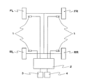
図1に示されるように、本発明の一実施の形態が適用されるタイヤ空気圧低下検出装置は、4輪車両に備えられた4つのタイヤFL、FR、RLおよびRRの空気圧が低下しているか否かを検出するもので、タイヤにそれぞれ関連して設けられた通常の回転角速度検出手段1を備えている。
【0015】
前記回転角速度検出手段1としては、電磁ピックアップなどを用いて回転パルスを発生させてパルスの数から回転角速度を測定する車輪速センサまたはダイナモのように回転を利用して発電を行ない、この電圧から回転角速度を測定するものを含む角速度センサなどを用いることができる。前記回転角速度検出手段1の出力はABSなどのコンピュータである制御ユニット2に与えられる。制御ユニット2には、空気圧が低下したタイヤを知らせるための液晶表示素子、プラズマ表示素子またはCRTなどで構成された表示器3、および初期補正係数K1、K2、K3を算出する際にドライバーによって操作する初期化スイッチ4が接続されている。この初期補正係数K1〜K3は、各タイヤ間の初期差異による有効ころがり半径の差を回転角速度から排除するためのものである。
【0016】
制御ユニット2は、図2に示されるように、外部装置との信号の受け渡しに必要なI/Oインターフェイス2aと、演算処理の中枢として機能するCPU2bと、該CPU2bの制御動作プログラムが格納されたROM2cと、前記CPU2bが制御動作を行なう際にデータなどが一時的に書き込まれたり、その書き込まれたデータなどが読み出されるRAM2dとから構成されている。該RAM2dの記憶領域の一部は、初期補正係数を算出するために用いられるカウンタとして利用される。EEPROM2eには、算出された初期補正係数が格納される。
【0017】
前記回転角速度検出手段1では、タイヤの回転数に対応したパルス信号(以下、車輪速パルスという)が出力される。また、CPU2bでは、回転角速度検出手段1から出力された車輪速パルスに基づき、所定のサンプリング周期ΔT(sec)、たとえばΔT=1秒ごとに各タイヤの回転角速度Fiが算出される。この回転角速度Fiに対して初期補正計算処理が施される。本発明における初期補正係数の計算処理は、とくに限定されるものではないが、たとえば初期補正係数K1、K2は、たとえばつぎの式(9)、(10)より算出することができる。
K1=BK1×(N−1)/N+(F1/F2)/N ・・・(9)
K2=BK2×(N−1)/N+(F4/F3)/N ・・・(10)
【0018】
ここで、初期補正係数K1は、前左右タイヤFL、FRのあいだの初期差異による有効ころがり半径の差を排除するための係数である。初期補正係数K2は、後左右タイヤRL、RRのあいだの初期差異による有効ころがり半径の差を排除するための係数である。また、BK1、BK2は、従前のサンプリング周期において求められたのち、RAM2dに保存された初期補正係数である。また、Nは初期補正係数の演算回数である。
【0019】
そして、タイヤの空気圧低下(減圧)の判定は、前記初期補正係数K1、K2を用いて、つぎの式(11)〜(14)に示されるように各タイヤ間の初期差異による有効ころがり半径の差が排除される回転角速度F1iを求めたのち、つぎの式(15)により算出された判定値Dに基づいて、空気圧が低下しているか否かが判別される。なお、本実施の形態では、初期補正係数K1、K2を用いて回転角速度を補正しているが、本発明においては、これに限定されるものではなく、初期補正係数K1、K2、K3を用いて回転角速度を補正することもできる。
F11=F1 ・・・(11)
F12=K1×F2 ・・・(12)
F13=F3 ・・・(13)
F14=K2×F4 ・・・(14)
DEL={(F11+F14)/2−(F12+F13)/2}/{(F11+F12+F13+F14)/4}×100(%) ・・・(15)
【0020】
本実施の形態では、前記初期補正係数の計算処理を行なうに際し、たとえば高速旋回走行以外の中低速走行(直線走行または中低旋回走行)をしていときのデータなどから基準となる判定値を求める。ただし、この基準判定値を求めるための回転角速度は、初期補正係数で補正される前の回転角速度を使う。かかる基準判定値と現在の判定値とのあいだの関係値(たとえば差または比)が所定のしきい値以上離れている場合、高速旋回走行中であると判断してこのときのデータをリジェクトする。これにより、本実施の形態では、正確な初期補正係数が求められるため、誤報がなくなり、安定走行を維持することができる。
【0021】
本実施の形態にかかわる初期補正係数演算装置は、前記回転角速度からタイヤの空気圧が低下しているか否かを判定する判定値を算出する判定値演算手段と、前記判定値に基づいて、車両が高速旋回走行、直線走行または中低速旋回走行しているか否かを識別する識別手段と、該識別手段により車両が直線走行または中低旋回走行していると識別される場合に、前記各タイヤ間の初期差異による有効ころがり半径の差を前記回転角速度から排除するための初期補正係数を求める初期補正係数演算手段とを備えている。また、前記識別手段は、算出される判定値と従前に求められた基準判定値との差または比の値が予め定めたしきい値未満であるか否かを判別する制限処理手段と、該差または比の値が前記しきい値未満であると判断される場合、前記車両が直線走行または中低速旋回走行していると判断する走行判断手段を含んでいる。
【0022】
また、本実施の形態では、基準判定手段を備えており、該基準判定手段により判定値Dおよび従前に求められた判定値BDに基づいて、つぎの式(16)に示されるように、平均化処理を行なうことにより基準判定値SDを求めている。
SD=D/N+BD×(N−1)/N ・・・(16)
【0023】
ここで、Nは、初期基準判定値の演算回数を記録する第1記録手段である初期化進捗度カウンタのカウント値(演算回数)である。
【0024】
前記基準判定値は、サンプリング周期ΔTごとにノイズ除去のためのフィルター処理をしたのち、算出されるため、その精度は演算が行なわれるたびによくなる。したがって、前記識別処理は、最初から高精度に行なうことができるように、基準判定値の精度が充分に出てから行なうようにする。そこで、本実施の形態では、前記識別手段における識別処理の実行を行なうのに先立ち、精度が充分に出るまでの基準判定値を判定値置換え手段により初期基準判定値とみなしている。
【0025】
また、本実施の形態では、前記演算回数が予め定めたしきい値、たとえば10未満であるか否かを判別する回数判別手段と、該演算回数がしきい値未満であると判断される場合、基準判定値の精度はまだ不充分であると判断されるため、前記初期基準判定値を求める処理のみを行ない、前記識別手段における識別処理の実行を禁止する実行禁止手段と、前記識別手段において、最初に用いられる基準判定値として、前記初期基準判定値を設定する設定手段を備えている。
【0026】
さらに本実施の形態では、前記識別手段が、車両が高速旋回走行していると識別される識別回数を記録する第2記録手段と、該識別回数が予め定めたしきい値以上であるか否かを判別する識別回数判別手段と、該識別回数がしきい値以上であると判断される場合、初期補正係数を初期化する初期化実施手段を含むのが好ましい。これにより、車両が高速旋回走行していると識別された回数がしきい値に達した場合に、初期補正係数の演算が最初からやり直されるため、高精度な初期補正係数を確実に得ることができる。
【0027】
そして、本実施の形態における初期補正係数演算のプログラムは、制御ユニット2を、判定値演算手段、識別手段、初期補正係数演算手段、制限処理手段、走行判断手段、基準判定手段、判定値置換え手段、第1記録手段、回数判別手段、実行禁止手段、設定手段、第2記録手段、識別回数判別手段、初期化実施手段として機能させる。
【0028】
以下、図3〜4に基づいて本実施の形態にかかわる初期補正係数演算装置の動作の手順(1)〜(5)について説明する。
【0029】
(1)回転角速度検出手段、たとえばABSセンサなどのセンサの出力に基づいて、車両の4輪タイヤFL、FR、RLおよびRRのそれぞれの回転角速度F1、F2、F3、F4を算出する(ステップS1)。
【0030】
(2)ついで回転角速度F1、F2、F3、F4から平均回転角速度を演算する(ステップS2)。
【0031】
(3)ついで前記式(15)を用いて、現在の判定値Dを演算する(ステップS3)。
【0032】
(4)ついで基準判定値SDを前記式(16)により演算する(ステップS4)。
【0033】
(5)ついで判定値の基準判定値からの制限処理を実施する(ステップS5)。
【0034】
(i)この制限処理では、識別処理を行なうのに先立ち、図4に示されるように、初期化進捗度カウンタのカウント値Nが所定のしきい値Hth、たとえば10未満であるか否かが判別される(ステップSS1)。その結果、カウント値Nがしきい値未満であると判別された場合には、基準判定値の精度はまだ不充分であると判断されるため、識別処理は行なわずに(識別処理の実施を禁止して)、初期基準判定値の算出が直接行なわれる。具体的には、10未満の場合はキャリーフラグ(CY)をゼロにセットしたのち(ステップSS2)、初期補正係数の計算処理(ステップS7)を行なうことなく、カウント値Nが「1」だけインクリメントされ、初期基準判定値の演算回数が記録される(ステップS8)。
【0035】
(ii)ついでカウント値Nが所定のしきい値Hth(たとえば10)以上の場合、識別手段において、最初に用いられる基準判定値として、初期基準判定値を設定したのち、ステップSS3に進み、│基準判定値−判定値│が基準判定値からの制限処理用しきい値Dth、たとえば0.08未満であるか否かが判別される。しきい値Dth未満であると判断される場合、すなわち直線走行または中低速旋回走行していると識別される場合、キャリーフラグ(CY)をゼロにセットしたのち(ステップSS4)、車両が高速旋回走行していると識別するための初期化異常検出カウンタのカウンタ値Cをクリアし(ステップSS5)、データをリジェクトすることなく(ステップS6)、初期補正係数の計算処理を行なう(ステップS7)。そして、カウント値Nが「1」だけインクリメントされ、初期基準判定値の演算回数が記録される(ステップS8)。
【0036】
(iii)前記│基準判定値−判定値│がしきい値Dth以上である場合、すなわち高速旋回走行していると識別される場合、初期化異常検出カウンタのカウンタ値Cが「1」だけインクリメントされる(ステップSS6)。
【0037】
(iv)ついで前記カウンタ値Cが所定のしきい値Cth、たとえば90以上であるか否かが判別される(ステップSS7)。その結果、カウント値Cがしきい値Cth以上であると判断される場合には、基準判定値が高速旋回走行中の判定値から求められた可能性があるため、カウンタ値Cをしきい値Cthに設定したのち、初期化開始要求をセットする(ステップSS8、SS9)。そして、今回だけ保存されている初期補正係数の計算処理をしないようにするために、キャリーフラグ(CY)を1にセットする(ステップSS10)。一方、前記カウント値Cがしきい値Cth未満であると判断される場合には、そのままキャリーフラグ(CY)を1にセットする(ステップSS10)。ついで制限処理の結果、高速旋回走行中のデータがリジェクトされた場合、前記ステップS1から繰り返される。
【0038】
つぎに本発明を実施例に基づいて説明するが、本発明はかかる実施例のみに限定されるものではない。
【0039】
【実施例】
車両として、正常空気圧(2.2×10⁵Pa)のタイヤが装着されたFF(フロントエンジン・フロントドライブ)車を用意した。前記タイヤのタイヤサイズは205/60R16である。走行コースとしてオーバルコースを採用した。そして、車両の走行条件として、直線コースを50km/hから旋回コースを50km/hで走行したのち、つぎの直線コースを100km/hおよび旋回コースを100km/hで走行する手順を繰り返す条件を採用した。
【0040】
一般に、前輪の初期補正係数K1と後輪の初期補正係数K2との比は、直線走行と旋回走行の時間によって変わることが知られている。そこで、本実施例では、効果の度合いを見る指標として、前輪の初期補正係数K1と後輪の初期補正係数K2との比K1/K2を調べた。その結果を図5に示す。図5において、実施例は前記実施の形態にかかわる初期補正係数演算装置における制限処理により、高速旋回中のデータをリジェクトし、算出した初期補正係数の比K1/K2であり、比較例は従来の初期補正係数演算装置により算出した初期補正係数の比K1/K2である。また、比較のため、直線コースを50km/hで走行させたときのデータから算出される初期補正係数の比(真値)K1/K2も調べた。なお、図5において、車両の走行状況をわかりやすくするために、50km/hの直線走行H1、50km/hの旋回走行H2、100km/hの直線走行H3、100km/hの旋回走行H4を示した。
【0041】
図5より、本実施例の初期補正係数の比K1/K2は、真値に近づいていることがわかる。これに対し、比較例の初期補正係数の比K1/K2は、真値から大きくずれていることがわかる。したがって、本発明は、オーバルコースを同じ方向に走行した場合でも、正確な初期補正係数を求めることができる。
【0042】
【発明の効果】
以上説明したとおり、本発明によれば、正確な初期補正係数を求めることができるため、たとえばタイヤの空気圧低下を正確に検出し、安全走行を維持することができる。
【図面の簡単な説明】
【図1】本発明の一実施の形態が適用されるタイヤ空気圧低下検出装置を示すブロック図である。
【図2】図1のタイヤ空気圧低下検出装置の電気的構成を示すブロック図である。
【図3】本実施の形態にかかわる初期補正係数演算装置のフローチャートの一例である。
【図4】初期補正係数演算装置における制限処理のフローチャートの一例である。
【図5】前輪と後輪の初期補正係数の比K1/K2の時間経過を示す図である。
【符号の説明】
1 回転角速度検出手段
2 制御ユニット
3 表示器
4 初期化スイッチ[0001]
BACKGROUND OF THE INVENTION
The present invention relates to an initial correction coefficient calculation apparatus and method, and an initial correction coefficient calculation program. More specifically, a tire pressure drop detection device (DWS) that detects tire pressure reduction from rotation (wheel speed) information of a four-wheel tire mounted on a vehicle or a drive wheel tire among four-wheel tires mounted on a vehicle. The present invention relates to an initial correction coefficient calculation apparatus and method used in a slip ratio calculation apparatus for calculating a slip ratio, and an initial correction coefficient calculation program.
[0002]
[Prior art]
Conventionally, the tire pressure drop detection device (DWS) is said that when the tire is depressurized, the outer diameter (the dynamic load radius of the tire) is smaller than that of a tire having a normal inner pressure, so that the rotational angular velocity is increased compared to other normal tires. The principle is used. For example, in the method of detecting a decrease in internal pressure from the relative difference in the rotational angular velocity of the tire,
[0003]
By the way, since tires are manufactured with variations (initial differences) within the standard, the effective rolling radius of each tire (the value obtained by dividing the distance advanced by one rotation by 2π) is normal even for all tires. Even the internal pressure is not necessarily the same. Therefore, the rotational angular velocity Fi of each tire varies. Therefore, for example, there is a method of eliminating the influence of the initial difference from the rotational angular velocity Fi (Patent Document 2). In this method, first, initial correction coefficients K1, K2, and K3 shown below are calculated.
K1 = F1 / F2 (2)
K2 = F3 / F4 (3)
K3 = (F1 + K1 × F2) / (F2 + K2 × F4) (4)
[0004]
Next, a new rotational angular velocity F1 i is obtained using the calculated initial correction coefficients K1, K2, and K3 as shown in equations (5) to (8).
F1 1 = F1 (5)
F1 2 = K1 × F2 (6)
F1 3 = K3 × F3 (7)
F1 4 = K2 × K3 × F4 (8)
[0005]
Here, the initial correction coefficient K1 is a coefficient for correcting the difference in effective rolling radius due to the initial difference between the front left and right tires. The initial correction coefficient K2 is a coefficient for correcting the difference in effective rolling radius due to the initial difference between the rear left and right tires. The initial correction coefficient K3 is a coefficient for correcting a difference in effective rolling radius due to an initial difference between the front left tire and the rear left and right tires.
[0006]
The initial correction coefficient calculated from the data obtained when the vehicle is running straight is different from the initial correction coefficient calculated only from the data during turning, but the initial correction coefficient during straight running and turning is increased or decreased by the same ratio. To do. For this reason, conventionally, the initial correction coefficient is obtained by using the fact that the judgment value at the time of the straight running and the turning run becomes the same value as a result of the calculation of the formula (1).
[0007]
[Patent Document 1]
Japanese Patent Laid-Open No. 63-305011 [Patent Document 2]
JP-A-9-249010 [0008]
[Problems to be solved by the invention]
However, the rotational angular velocity varies due to the difference in load movement applied to the tire during high-speed turning and the difference in slip ratio between the inner and outer wheels of the driving wheels during high-speed turning. For this reason, if the initial correction coefficient is calculated by taking in data during high-speed turning, an accurate initial correction coefficient cannot be obtained.
[0009]
In view of the above circumstances, an object of the present invention is to provide an initial correction coefficient calculation apparatus and method capable of obtaining an accurate initial correction coefficient, and an initial correction coefficient calculation program.
[0010]
[Means for Solving the Problems]
An initial correction coefficient calculation device according to the present invention calculates an initial correction coefficient for correcting a rotation angular velocity obtained from the output of rotation angular velocity detection means provided in association with four tires mounted on a vehicle. A calculation device, a determination value calculation means for calculating a determination value for determining whether or not the tire air pressure is reduced from the rotational angular velocity, and based on the determination value, An identification means for identifying whether the vehicle is running at a medium or low speed, and an effective rolling radius due to an initial difference between the tires when the identification means identifies that the vehicle is traveling straight or running at a medium to low speed. Initial correction coefficient calculating means for obtaining an initial correction coefficient for eliminating the difference between the rotational angular velocities and the identification means previously obtained with the calculated determination value. Limiting processing means for determining whether or not a difference or ratio value with respect to the reference determination value is less than a predetermined threshold value, and determining that the difference or ratio value is less than the threshold value In this case, the vehicle is characterized in that it includes a traveling determination means for determining that the vehicle is traveling straight or traveling at a medium to low speed.
[0011]
An initial correction coefficient calculation method according to the present invention is an initial correction coefficient for calculating an initial correction coefficient for correcting a rotation angular velocity obtained from an output of a rotation angular velocity detection means provided in association with each of four tires mounted on a vehicle. A calculation method comprising: calculating a determination value for determining whether or not the tire air pressure is reduced from the rotational angular velocity; and based on the determination value, the vehicle is traveling at a high speed turning, a straight traveling, or a medium / low speed turning. A step of identifying whether or not the vehicle is running, and a difference in effective rolling radius due to an initial difference between the tires when the identification means identifies that the vehicle is traveling straight or turning at a medium or low speed. A step of obtaining an initial correction coefficient for excluding from the rotational angular velocity, wherein the step of identifying is a difference between a calculated determination value and a previously determined reference determination value or Determining whether or not the value of the vehicle is less than a predetermined threshold value, and if it is determined that the value of the difference or ratio is less than the threshold value, the vehicle is traveling straight or turning at a medium to low speed The method includes a step of determining that the vehicle is traveling.
[0012]
An initial correction coefficient calculation program according to the present invention is for calculating an initial correction coefficient for correcting a rotation angular velocity obtained from an output of a rotation angular velocity detection means provided in association with each of four tires mounted on a vehicle. A determination value calculating means for calculating a determination value for determining whether or not the tire air pressure is reduced from the rotational angular velocity; and based on the determination value, the vehicle is driven at a high speed turning, a straight running or a medium / low speed turning Identification means for identifying whether or not the vehicle is running, and when the identification means identifies that the vehicle is running straight or turning at a medium to low speed, the difference in effective rolling radius due to the initial difference between the tires is In addition to functioning as an initial correction coefficient calculation means for obtaining an initial correction coefficient to be excluded from the angular velocity, the calculated judgment value and the previously obtained reference standard Limiting processing means for determining whether or not the difference or ratio value is less than a predetermined threshold value, and if the difference or ratio value is determined to be less than the threshold value, the vehicle It is made to function as a travel judgment means which judges that is carrying out the straight run or the middle-low speed turning run.
[0013]
DETAILED DESCRIPTION OF THE INVENTION
Hereinafter, an initial correction coefficient calculation apparatus and method, and an initial correction coefficient calculation program according to the present invention will be described with reference to the accompanying drawings.
[0014]
As shown in FIG. 1, in the tire pressure drop detecting device to which one embodiment of the present invention is applied, the pressures of the four tires FL, FR, RL and RR provided in the four-wheel vehicle are lowered. A normal rotational angular velocity detection means 1 provided in association with each tire.
[0015]
The rotational angular velocity detection means 1 generates electric power using rotation like a wheel speed sensor or dynamo that generates a rotational pulse using an electromagnetic pickup or the like and measures the rotational angular velocity from the number of pulses. An angular velocity sensor including one that measures the rotational angular velocity can be used. The output of the rotational angular velocity detection means 1 is given to a
[0016]
As shown in FIG. 2, the
[0017]
The rotational angular velocity detection means 1 outputs a pulse signal (hereinafter referred to as wheel speed pulse) corresponding to the number of rotations of the tire. Further, the
K1 = BK1 × (N−1) / N + (F1 / F2) / N (9)
K2 = BK2 × (N−1) / N + (F4 / F3) / N (10)
[0018]
Here, the initial correction coefficient K1 is a coefficient for eliminating the difference in effective rolling radius due to the initial difference between the front left and right tires FL, FR. The initial correction coefficient K2 is a coefficient for eliminating a difference in effective rolling radius due to an initial difference between the rear left and right tires RL and RR. BK1 and BK2 are initial correction coefficients obtained in the previous sampling period and stored in the
[0019]
The tire pressure drop (reduced pressure) is determined using the initial correction coefficients K1 and K2, as shown in the following equations (11) to (14). After obtaining the rotational angular velocity F1 i from which the difference is eliminated, it is determined based on the determination value D calculated by the following equation (15) whether or not the air pressure has decreased. In this embodiment, the rotational angular velocity is corrected using the initial correction coefficients K1 and K2. However, the present invention is not limited to this, and the initial correction coefficients K1, K2, and K3 are used. It is also possible to correct the rotational angular velocity.
F1 1 = F1 (11)
F1 2 = K1 × F2 (12)
F1 3 = F3 (13)
F1 4 = K2 × F4 (14)
DEL = {(F1 1 + F1 4 ) / 2− (F1 2 + F1 3 ) / 2} / {(F1 1 + F1 2 + F1 3 + F1 4 ) / 4} × 100 (%) (15)
[0020]
In the present embodiment, when the calculation process of the initial correction coefficient is performed, a reference determination value is obtained from, for example, data when the vehicle is running at a medium to low speed (straight running or medium to low turning) other than high-speed turning. . However, the rotational angular velocity for obtaining the reference determination value is the rotational angular velocity before being corrected by the initial correction coefficient. When the relationship value (for example, difference or ratio) between the reference determination value and the current determination value is more than a predetermined threshold, it is determined that the vehicle is turning at a high speed and the data at this time is rejected. . Thereby, in this Embodiment, since an exact initial correction coefficient is calculated | required, there is no misreport and it can maintain stable driving | running | working.
[0021]
The initial correction coefficient calculation device according to the present embodiment is configured to calculate a determination value for determining whether or not the tire air pressure is reduced from the rotational angular velocity, and based on the determination value, the vehicle An identification means for identifying whether or not the vehicle is traveling at a high speed, straight or medium / low speed, and when the vehicle is identified as traveling straight or at a medium or low speed by the identification means, Initial correction coefficient calculation means for obtaining an initial correction coefficient for eliminating the difference in effective rolling radius due to the initial difference from the rotational angular velocity. Further, the identification means includes a restriction processing means for determining whether or not a difference or ratio value between the calculated determination value and the previously determined reference determination value is less than a predetermined threshold value, When it is determined that the value of the difference or ratio is less than the threshold value, the vehicle includes a travel determination unit that determines that the vehicle is traveling straight or traveling at a medium to low speed.
[0022]
Further, in the present embodiment, a reference determination unit is provided, and based on the determination value D and the determination value BD previously obtained by the reference determination unit, as shown in the following equation (16), the average The reference determination value SD is obtained by performing the conversion process.
SD = D / N + BD × (N−1) / N (16)
[0023]
Here, N is a count value (number of calculations) of an initialization progress counter which is a first recording unit that records the number of calculations of the initial reference determination value.
[0024]
Since the reference determination value is calculated after filtering processing for noise removal at every sampling period ΔT, the accuracy of the reference determination value is improved every time an operation is performed. Therefore, the identification process is performed after the accuracy of the reference determination value is sufficiently high so that the identification process can be performed with high accuracy from the beginning. Therefore, in the present embodiment, prior to performing the identification process in the identification unit, the reference determination value until sufficient accuracy is obtained is regarded as the initial reference determination value by the determination value replacement unit.
[0025]
Further, in the present embodiment, the number determination means for determining whether or not the number of calculations is a predetermined threshold, for example, less than 10, and the case where it is determined that the number of calculations is less than the threshold Since it is determined that the accuracy of the reference determination value is still inadequate, only the process for obtaining the initial reference determination value is performed, and the execution prohibiting means for prohibiting the execution of the identification process in the identifying means, and the identifying means A setting means for setting the initial reference determination value as a reference determination value to be used first is provided.
[0026]
Furthermore, in the present embodiment, the identification unit records the number of times of identification for identifying that the vehicle is turning at high speed, and whether or not the number of identifications is equal to or greater than a predetermined threshold value. It is preferable to include an identification number determination means for determining whether or not and an initialization execution means for initializing an initial correction coefficient when it is determined that the identification number is equal to or greater than a threshold value. As a result, when the number of times that the vehicle is identified as traveling at a high speed reaches a threshold value, the calculation of the initial correction coefficient is performed again from the beginning, so that a highly accurate initial correction coefficient can be reliably obtained. it can.
[0027]
The initial correction coefficient calculation program according to the present embodiment uses the
[0028]
Hereinafter, the operation procedures (1) to (5) of the initial correction coefficient computing device according to the present embodiment will be described with reference to FIGS.
[0029]
(1) The rotational angular velocities F1, F2, F3, and F4 of the four-wheel tires FL, FR, RL, and RR of the vehicle are calculated based on the output of a rotational angular velocity detecting means, for example, a sensor such as an ABS sensor (step S1). ).
[0030]
(2) Next, the average rotational angular velocity is calculated from the rotational angular velocities F1, F2, F3, and F4 (step S2).
[0031]
(3) Next, the current determination value D is calculated using the equation (15) (step S3).
[0032]
(4) Next, the reference judgment value SD is calculated by the above equation (16) (step S4).
[0033]
(5) Next, a process of limiting the determination value from the reference determination value is performed (step S5).
[0034]
(i) In this limiting process, prior to the identification process, as shown in FIG. 4, it is determined whether or not the count value N of the initialization progress counter is less than a predetermined threshold value Hth, for example, 10. It is determined (step SS1). As a result, when it is determined that the count value N is less than the threshold value, it is determined that the accuracy of the reference determination value is still insufficient, so the identification process is not performed (the identification process is performed). Forbidden), the initial reference judgment value is calculated directly. Specifically, if it is less than 10, the carry flag (CY) is set to zero (step SS2), and the count value N is incremented by “1” without performing the initial correction coefficient calculation process (step S7). Then, the number of calculations of the initial reference determination value is recorded (step S8).
[0035]
(ii) If the count value N is equal to or greater than a predetermined threshold Hth (for example, 10), the identification unit sets an initial reference determination value as a reference determination value to be used first, and then proceeds to step SS3. It is determined whether or not the reference determination value−the determination value | is less than a threshold value Dth for restriction processing from the reference determination value, for example, less than 0.08. When it is determined that the vehicle is less than the threshold value Dth, that is, when it is determined that the vehicle is traveling straight or turning at medium / low speed, the carry flag (CY) is set to zero (step SS4), and then the vehicle turns at high speed. The counter value C of the initialization abnormality detection counter for identifying that the vehicle is traveling is cleared (step SS5), and the initial correction coefficient is calculated without rejecting the data (step S6) (step S7). Then, the count value N is incremented by “1”, and the number of calculations of the initial reference determination value is recorded (step S8).
[0036]
(iii) If the | reference determination value−determination value | is greater than or equal to the threshold value Dth, that is, if it is identified that the vehicle is turning at a high speed, the counter value C of the initialization abnormality detection counter is incremented by “1”. (Step SS6).
[0037]
(iv) Next, it is determined whether or not the counter value C is a predetermined threshold value Cth, for example, 90 or more (step SS7). As a result, if it is determined that the count value C is greater than or equal to the threshold value Cth, the reference determination value may be obtained from the determination value during high-speed turning, so the counter value C is set to the threshold value. After setting to Cth, an initialization start request is set (steps SS8 and SS9). Then, the carry flag (CY) is set to 1 in order not to calculate the initial correction coefficient stored only this time (step SS10). On the other hand, when it is determined that the count value C is less than the threshold value Cth, the carry flag (CY) is set to 1 as it is (step SS10). If the data during high speed turning is rejected as a result of the restriction process, the process is repeated from step S1.
[0038]
Next, the present invention will be described based on examples, but the present invention is not limited to such examples.
[0039]
【Example】
As a vehicle, an FF (front engine / front drive) vehicle equipped with tires of normal air pressure (2.2 × 10 5 Pa) was prepared. The tire size is 205 / 60R16. The oval course was adopted as the running course. Then, as a running condition of the vehicle, a condition is adopted in which a straight course is run from 50 km / h to a turning course at 50 km / h, and then the next straight course is run at 100 km / h and the turning course is run at 100 km / h. did.
[0040]
In general, it is known that the ratio between the initial correction coefficient K1 for the front wheels and the initial correction coefficient K2 for the rear wheels varies depending on the time of straight travel and turning travel. Therefore, in this embodiment, the ratio K1 / K2 between the initial correction coefficient K1 for the front wheels and the initial correction coefficient K2 for the rear wheels was examined as an index for determining the degree of effect. The result is shown in FIG. In FIG. 5, the example is the ratio K1 / K2 of the initial correction coefficient calculated by rejecting the data during high-speed turning by the limiting process in the initial correction coefficient calculating apparatus according to the embodiment, and the comparative example is a conventional example. The initial correction coefficient ratio K1 / K2 calculated by the initial correction coefficient calculation device. For comparison, the ratio (true value) K1 / K2 of the initial correction coefficient calculated from the data when the straight course was run at 50 km / h was also examined. In FIG. 5, in order to make it easy to understand the traveling state of the vehicle, a straight traveling H1 of 50 km / h, a turning traveling H2 of 50 km / h, a linear traveling H3 of 100 km / h, and a turning traveling H4 of 100 km / h are shown. It was.
[0041]
From FIG. 5, it can be seen that the ratio K1 / K2 of the initial correction coefficient of this embodiment is close to the true value. On the other hand, it can be seen that the ratio K1 / K2 of the initial correction coefficient in the comparative example is greatly deviated from the true value. Therefore, according to the present invention, an accurate initial correction coefficient can be obtained even when traveling on the oval course in the same direction.
[0042]
【The invention's effect】
As described above, according to the present invention, since an accurate initial correction coefficient can be obtained, for example, a decrease in tire air pressure can be accurately detected, and safe running can be maintained.
[Brief description of the drawings]
FIG. 1 is a block diagram showing a tire pressure drop detecting device to which an embodiment of the present invention is applied.
FIG. 2 is a block diagram showing an electrical configuration of the tire pressure drop detecting device of FIG. 1;
FIG. 3 is an example of a flowchart of an initial correction coefficient calculation apparatus according to the present embodiment.
FIG. 4 is an example of a flowchart of a limiting process in the initial correction coefficient computing device.
FIG. 5 is a diagram showing the passage of time of a ratio K1 / K2 of initial correction coefficients of front wheels and rear wheels.
[Explanation of symbols]
1 Rotational angular velocity detection means 2
Claims (6)
Priority Applications (3)
| Application Number | Priority Date | Filing Date | Title |
|---|---|---|---|
| JP2003138928A JP3777169B2 (en) | 2003-05-16 | 2003-05-16 | Initial correction coefficient calculation device and method, and initial correction coefficient calculation program |
| US10/826,283 US7395145B2 (en) | 2003-05-16 | 2004-04-19 | Apparatus and method for calculating initial correction coefficient, and program for calculating initial correction coefficient |
| EP04009360A EP1477337A3 (en) | 2003-05-16 | 2004-04-20 | Apparatus and method for calculating initial correction coefficient |
Applications Claiming Priority (1)
| Application Number | Priority Date | Filing Date | Title |
|---|---|---|---|
| JP2003138928A JP3777169B2 (en) | 2003-05-16 | 2003-05-16 | Initial correction coefficient calculation device and method, and initial correction coefficient calculation program |
Publications (2)
| Publication Number | Publication Date |
|---|---|
| JP2004340801A JP2004340801A (en) | 2004-12-02 |
| JP3777169B2 true JP3777169B2 (en) | 2006-05-24 |
Family
ID=33028420
Family Applications (1)
| Application Number | Title | Priority Date | Filing Date |
|---|---|---|---|
| JP2003138928A Expired - Fee Related JP3777169B2 (en) | 2003-05-16 | 2003-05-16 | Initial correction coefficient calculation device and method, and initial correction coefficient calculation program |
Country Status (3)
| Country | Link |
|---|---|
| US (1) | US7395145B2 (en) |
| EP (1) | EP1477337A3 (en) |
| JP (1) | JP3777169B2 (en) |
Families Citing this family (7)
| Publication number | Priority date | Publication date | Assignee | Title |
|---|---|---|---|---|
| JP4663612B2 (en) | 2005-12-09 | 2011-04-06 | 住友ゴム工業株式会社 | Tire pressure abnormality detection device, method and program |
| KR100802833B1 (en) | 2006-12-14 | 2008-02-12 | 현대자동차주식회사 | Apparatus and method for learning tire accompanying diameter of vehicle |
| FR2927017B1 (en) | 2008-01-31 | 2011-05-20 | Renault Sas | METHOD FOR CALIBRATING A TIRE DETECTING SIGNAL OF A TIRE OF A VEHICLE |
| US8140263B2 (en) * | 2008-01-31 | 2012-03-20 | Victor Company Of Japan, Limited | Method for deriving conversion coefficient used for specifying position from value detected by various sensors, and navigation apparatus |
| GB2464734A (en) * | 2008-10-24 | 2010-04-28 | Transense Technologies Plc | Providing sensor device specific calibration coefficients for sensor based measurements |
| CN109405932B (en) * | 2017-12-21 | 2024-05-07 | 金卡智能集团股份有限公司 | Meter metering value self-correction method suitable for flowmeter and meter metering method |
| CN115268449B (en) * | 2022-07-29 | 2024-07-19 | 格力博(江苏)股份有限公司 | Mower and calibration method thereof |
Family Cites Families (9)
| Publication number | Priority date | Publication date | Assignee | Title |
|---|---|---|---|---|
| JPH07156621A (en) | 1993-12-07 | 1995-06-20 | Sumitomo Electric Ind Ltd | Initial correction method for tire inflation pressure lowering detection device |
| US5710539A (en) | 1993-12-07 | 1998-01-20 | Sumitomo Electric Industrties, Ltd. | Tire air-pressure reduction detecting apparatus |
| JPH07260810A (en) * | 1994-03-18 | 1995-10-13 | Honda Motor Co Ltd | Apparatus for correcting speed of wheel |
| JP3724852B2 (en) * | 1995-09-19 | 2005-12-07 | 本田技研工業株式会社 | Anti-lock brake control device for vehicle |
| JP3158038B2 (en) | 1996-03-14 | 2001-04-23 | 住友電気工業株式会社 | Tire pressure drop detector |
| JP3231256B2 (en) | 1997-01-27 | 2001-11-19 | 住友電気工業株式会社 | Initial correction coefficient calculator |
| JP3299682B2 (en) | 1997-02-27 | 2002-07-08 | 住友電気工業株式会社 | Initial correction coefficient calculator |
| JP3344923B2 (en) | 1997-04-14 | 2002-11-18 | 住友電気工業株式会社 | Initial correction device in tire pressure drop detection device |
| US6759952B2 (en) * | 2001-07-06 | 2004-07-06 | Trw Inc. | Tire and suspension warning and monitoring system |
-
2003
- 2003-05-16 JP JP2003138928A patent/JP3777169B2/en not_active Expired - Fee Related
-
2004
- 2004-04-19 US US10/826,283 patent/US7395145B2/en not_active Expired - Fee Related
- 2004-04-20 EP EP04009360A patent/EP1477337A3/en not_active Withdrawn
Also Published As
| Publication number | Publication date |
|---|---|
| EP1477337A3 (en) | 2005-01-05 |
| EP1477337A2 (en) | 2004-11-17 |
| US7395145B2 (en) | 2008-07-01 |
| US20040230349A1 (en) | 2004-11-18 |
| JP2004340801A (en) | 2004-12-02 |
Similar Documents
| Publication | Publication Date | Title |
|---|---|---|
| JP4463311B2 (en) | Tire pressure drop detection method and apparatus, and tire decompression determination program | |
| JP3299682B2 (en) | Initial correction coefficient calculator | |
| US7870780B2 (en) | Method for identifying vehicle wheels having low tire pressure | |
| JP3724892B2 (en) | Tire pressure drop detection method and apparatus | |
| JP3801945B2 (en) | Tire pressure drop detection method and apparatus, and tire decompression determination program | |
| JP3777169B2 (en) | Initial correction coefficient calculation device and method, and initial correction coefficient calculation program | |
| JP2008249523A (en) | Method, device and program for alarming abnormal drop in tire pneumatic pressure | |
| JP4534072B2 (en) | Tire pressure drop alarm device and method, and tire internal pressure drop judgment erasing program | |
| JP3923873B2 (en) | Tire pressure drop detection method and apparatus, and tire decompression determination program | |
| EP2455238B1 (en) | Apparatus and method for detecting decrease in tire air pressure and program for detecting decrease in tire air pressure | |
| EP2386431B1 (en) | Apparatus and method for detecting decrease in tire air pressure and program for detecting decrease in tire air pressure | |
| JP3869762B2 (en) | Tire pressure drop detection method and apparatus, and tire decompression determination program | |
| JP3971720B2 (en) | Tire pressure drop detection method and apparatus, and tire decompression determination program | |
| JP3834261B2 (en) | Tire pressure drop detection method and apparatus, and tire decompression determination program | |
| JP3929962B2 (en) | Tire pressure drop detection method and apparatus, and tire decompression determination program | |
| JP2003200724A (en) | Detecting method for differential restriction device, detecting method and device for air pressure drop of tire, and judging program for pressure drop of tire | |
| JP3929961B2 (en) | Tire pressure drop detection method and apparatus, and tire decompression determination program | |
| JP3167278B2 (en) | Method and apparatus for detecting decrease in tire air pressure | |
| JP3623023B2 (en) | Tire pressure drop detection method and apparatus | |
| JP3996842B2 (en) | Tire pressure drop detection method and apparatus, and tire decompression determination program | |
| JPH07156621A (en) | Initial correction method for tire inflation pressure lowering detection device | |
| JPH1076823A (en) | Tire pneumatic pressure reduction detecting method and device thereof | |
| JP3957656B2 (en) | Tire pressure drop detection method and apparatus, and tire decompression determination program | |
| JP2005205977A (en) | Tire pneumatic pressure lowering detection method and device, and program of tire decompression determination | |
| JP3626076B2 (en) | Tire pressure drop alarm device and method |
Legal Events
| Date | Code | Title | Description |
|---|---|---|---|
| TRDD | Decision of grant or rejection written | ||
| A01 | Written decision to grant a patent or to grant a registration (utility model) |
Free format text: JAPANESE INTERMEDIATE CODE: A01 Effective date: 20060214 |
|
| A61 | First payment of annual fees (during grant procedure) |
Free format text: JAPANESE INTERMEDIATE CODE: A61 Effective date: 20060224 |
|
| R150 | Certificate of patent or registration of utility model |
Free format text: JAPANESE INTERMEDIATE CODE: R150 |
|
| FPAY | Renewal fee payment (event date is renewal date of database) |
Free format text: PAYMENT UNTIL: 20090303 Year of fee payment: 3 |
|
| FPAY | Renewal fee payment (event date is renewal date of database) |
Free format text: PAYMENT UNTIL: 20100303 Year of fee payment: 4 |
|
| LAPS | Cancellation because of no payment of annual fees |