JP3773685B2 - Stabilizer for air suspension system - Google Patents
Stabilizer for air suspension system Download PDFInfo
- Publication number
- JP3773685B2 JP3773685B2 JP3563799A JP3563799A JP3773685B2 JP 3773685 B2 JP3773685 B2 JP 3773685B2 JP 3563799 A JP3563799 A JP 3563799A JP 3563799 A JP3563799 A JP 3563799A JP 3773685 B2 JP3773685 B2 JP 3773685B2
- Authority
- JP
- Japan
- Prior art keywords
- link arms
- thickness
- stabilizer
- plate
- torsion bar
- Prior art date
- Legal status (The legal status is an assumption and is not a legal conclusion. Google has not performed a legal analysis and makes no representation as to the accuracy of the status listed.)
- Expired - Lifetime
Links
Images


Classifications
-
- B—PERFORMING OPERATIONS; TRANSPORTING
- B60—VEHICLES IN GENERAL
- B60G—VEHICLE SUSPENSION ARRANGEMENTS
- B60G21/00—Interconnection systems for two or more resiliently-suspended wheels, e.g. for stabilising a vehicle body with respect to acceleration, deceleration or centrifugal forces
- B60G21/02—Interconnection systems for two or more resiliently-suspended wheels, e.g. for stabilising a vehicle body with respect to acceleration, deceleration or centrifugal forces permanently interconnected
- B60G21/04—Interconnection systems for two or more resiliently-suspended wheels, e.g. for stabilising a vehicle body with respect to acceleration, deceleration or centrifugal forces permanently interconnected mechanically
- B60G21/05—Interconnection systems for two or more resiliently-suspended wheels, e.g. for stabilising a vehicle body with respect to acceleration, deceleration or centrifugal forces permanently interconnected mechanically between wheels on the same axle but on different sides of the vehicle, i.e. the left and right wheel suspensions being interconnected
- B60G21/051—Trailing arm twist beam axles
-
- B—PERFORMING OPERATIONS; TRANSPORTING
- B60—VEHICLES IN GENERAL
- B60G—VEHICLE SUSPENSION ARRANGEMENTS
- B60G7/00—Pivoted suspension arms; Accessories thereof
- B60G7/001—Suspension arms, e.g. constructional features
-
- B—PERFORMING OPERATIONS; TRANSPORTING
- B60—VEHICLES IN GENERAL
- B60G—VEHICLE SUSPENSION ARRANGEMENTS
- B60G2200/00—Indexing codes relating to suspension types
- B60G2200/30—Rigid axle suspensions
- B60G2200/314—Rigid axle suspensions with longitudinally arranged arms articulated on the axle
-
- B—PERFORMING OPERATIONS; TRANSPORTING
- B60—VEHICLES IN GENERAL
- B60G—VEHICLE SUSPENSION ARRANGEMENTS
- B60G2200/00—Indexing codes relating to suspension types
- B60G2200/30—Rigid axle suspensions
- B60G2200/34—Stabilising mechanisms, e.g. for lateral stability
- B60G2200/341—Panhard rod
-
- B—PERFORMING OPERATIONS; TRANSPORTING
- B60—VEHICLES IN GENERAL
- B60G—VEHICLE SUSPENSION ARRANGEMENTS
- B60G2200/00—Indexing codes relating to suspension types
- B60G2200/40—Indexing codes relating to the wheels in the suspensions
- B60G2200/445—Self-steered wheels
-
- B—PERFORMING OPERATIONS; TRANSPORTING
- B60—VEHICLES IN GENERAL
- B60G—VEHICLE SUSPENSION ARRANGEMENTS
- B60G2202/00—Indexing codes relating to the type of spring, damper or actuator
- B60G2202/10—Type of spring
- B60G2202/13—Torsion spring
- B60G2202/136—Twist-beam type arrangement
-
- B—PERFORMING OPERATIONS; TRANSPORTING
- B60—VEHICLES IN GENERAL
- B60G—VEHICLE SUSPENSION ARRANGEMENTS
- B60G2202/00—Indexing codes relating to the type of spring, damper or actuator
- B60G2202/10—Type of spring
- B60G2202/13—Torsion spring
- B60G2202/136—Twist-beam type arrangement
- B60G2202/1362—Twist-beam type arrangement including a second torsional element, e.g. second beam, stabiliser bar or tube
-
- B—PERFORMING OPERATIONS; TRANSPORTING
- B60—VEHICLES IN GENERAL
- B60G—VEHICLE SUSPENSION ARRANGEMENTS
- B60G2202/00—Indexing codes relating to the type of spring, damper or actuator
- B60G2202/10—Type of spring
- B60G2202/15—Fluid spring
- B60G2202/152—Pneumatic spring
-
- B—PERFORMING OPERATIONS; TRANSPORTING
- B60—VEHICLES IN GENERAL
- B60G—VEHICLE SUSPENSION ARRANGEMENTS
- B60G2206/00—Indexing codes related to the manufacturing of suspensions: constructional features, the materials used, procedures or tools
- B60G2206/01—Constructional features of suspension elements, e.g. arms, dampers, springs
- B60G2206/10—Constructional features of arms
- B60G2206/121—Constructional features of arms the arm having an H or X-shape
-
- B—PERFORMING OPERATIONS; TRANSPORTING
- B60—VEHICLES IN GENERAL
- B60G—VEHICLE SUSPENSION ARRANGEMENTS
- B60G2206/00—Indexing codes related to the manufacturing of suspensions: constructional features, the materials used, procedures or tools
- B60G2206/01—Constructional features of suspension elements, e.g. arms, dampers, springs
- B60G2206/20—Constructional features of semi-rigid axles, e.g. twist beam type axles
Landscapes
- Engineering & Computer Science (AREA)
- Mechanical Engineering (AREA)
- Vehicle Body Suspensions (AREA)
Description
【0001】
【発明の属する技術分野】
本発明は、大型トラック、バス等に用いるのに適し、車体フレームとアクスルとを連結するべく車両前後方向に互いに平行に延在する左右一対のリンクアームを有するエアサスペンション装置用スタビライザに関するものである。
【0002】
【従来の技術】
従来から、大型トラック、バス等に用いられる車軸式サスペンション装置に於いて、リーフスプリングを用いたものに比較して乗り心地等が改善された空気ばねを用いたものが知られている。この空気ばねは、単体で用いると基本的には2点を作用点とし、幅や長さがないことから、板ばねと異なり、単体では前後・左右の連結ができず、公知の連結ロッド等を併用する必要がある。これには、例えば車体フレームとアクスルとを連結するべく車両前後方向に互いに平行に延在する左右一対のリンクアームと、その上側に同様な一対のリンクアームまたはV字ロッド状のリンクアームとを設けた平行リンク式のものがある。二対のリンクアームを設けたものにあっては、車体フレームとアクスルとを連結するラテラルロッドをも設けることが一般的である。
【0003】
上記の如きサスペンション装置にあっては、左右輪の揺れを抑制するためのスタビライザが別途設けられていることが多いが、このスタビライザの重量が20kg〜30kgと重く、車体の重量化を招いていた。
【0004】
このような不都合に対処するために、本願と同一出願人は、特願平9−223784号明細書に於いて、エアサスペンション装置の左右リンクアームを、上下方向よりも左右方向に撓みやすい板ばね状部材で形成し、その一端同士を左右方向に延在するトーションバーで連結し、各他端及びトーションバーのいずれか一方を車体側に連結すると共に他方をアクスルに連結し、両リンクアーム及びトーションバーにより左右輪の揺れを抑制するスタビライザを構成することを提案している。
【0005】
この構造によれば、別付スタビライザ及びスタビライザを車体フレームに支持するのに用いていたスタビハンガーブラケットを省略して車両重量が軽くなると共に部品点数が削減され、車両コストが低廉化される。
【0006】
【発明が解決しようとする課題】
上記構成のリンクアームに於いては、トーションバー側は剛結され、反トーションバー側はブシュを介して支持されるなど、トーションバー側と反トーションバー側とで可動範囲の差や支持構造の違いがあるので、トーションバー側の板厚よりも反トーションバー側の板厚を薄くした所謂テーパリーフを用いた方がばね定数の調整がし易くなると共に左右方向への撓み時にリンクアームの最大発生応力を低減できる。ところがその反面、反トーションバー側の板厚をあまり薄くするとその部分の強度が低下し、この逆に反トーションバー側の板厚を確保したままトーションバー側の板厚を厚くすると、リンクアームが過度に厚くなって装置が大型化・重量化するという問題が発生する。
【0007】
本発明は、このような従来技術の問題点に鑑みなされたものであり、その目的は、部分的な強度の低下を伴うことなく、また大型化・重量化を伴うことなくリンクアームの最大発生応力を低減し、耐久性を向上し得るエアサスペンション装置用スタビライザを提供することにある。
【0008】
【課題を解決するための手段】
上記した目的は、上下方向よりも左右方向に撓みやすい板ばね状部材からなり車両前後方向に互いに平行に延在して車体フレーム1、2とアクスル7とを連結する左右一対のリンクアーム8、9と、前記両リンクアームの一端同士を連結して左右方向に延在するトーションバー10とを有し、前記両リンクアームの他端及び前記トーションバーのいずれか一方をゴムブッシュまたはボールジョイントを介して前記車体フレーム側に結合すると共に他方をゴムブッシュまたはボールジョイントを介して前記アクスルに結合することによって左右輪Tの揺れを抑制するためのエアサスペンション装置用スタビライザであって、前記両リンクアームが、前記一端側の板厚D1に比較して前記他端側の板厚D2の方が薄くなっていると共にその間の前記他端側寄りに前記他端側の板厚よりも更に薄い板厚D3の部分を有し、且つ各部の板厚がなだらかに変化していることを特徴とするエアサスペンション装置用スタビライザを提供することにより達成される。特に、前記両リンクアームの両結合部間の長さをL1としたときに、前記一端側の板厚D1が2.75〜3.25×10⁻²×L1の範囲、前記他端側の板厚D2が1.5〜2.0×10−2×L1の範囲、前記他端側の板厚よりも更に薄い部分の板厚D3が0.85〜2.75×10−2×L1の範囲、とそれぞれなっていると良く、また、前記両リンクアームの両結合部間の長さをL1とし、前記両リンクアームの最も板厚の薄い部分の前記他端側の結合部からの距離をL2としたときに、L2/L1=0.25〜0.35の範囲となっていると良い。
【0009】
更に、前記両リンクアームが、前記一端側の板幅に比較して前記他端側の板幅の方が狭くなっていると共にその間の板幅がなだらかに変化していることで、最大応力低減効果が一層高くなる。その場合、前記両リンクアームの結合部間の長さをL1としたときに、前記一端側の板幅W1が0.325〜0.375×L1の範囲、前記他端側の板幅W2が0.25〜0.30×L1の範囲、とそれぞれなっており、かつW1/W2=1.1〜1.5の範囲となっていることが望ましい。
【0010】
【発明の実施の形態】
以下に、添付の図面を参照して本発明の好適な実施形態について詳細に説明する。
【0011】
図1〜図3は、本発明が適用された第1の実施形態に於けるトラックの従動輪のエアサスペンション装置の概略構成を示す。このサスペンション装置は、空気ばねを用いた車軸式サスペンション装置である。車体の左右に前後方向に延在するフレーム1、2には、一対のアッパーリンクアーム3、4の一端がブラケット5、6及びブッシュを介して主に上下方向に揺動可能に枢着されている。このアッパーリンクアーム3、4の他端には、ブッシュを介してアクスル7が連結されている。
【0012】
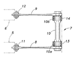
図2及び図3に良く示すように、アッパーリンクアーム3、4の下部には、これと平行にロアリンクアーム8、9が配置され、その一端同士が左右方向に延在するトーションバー10で一体的に剛結されている。また、ロアリンクアーム8、9の各他端は、フレーム1、2に、ブラケット5、6及びブシュ11、12を介して主に上下方向に揺動可能に枢着されている。トーションバー10の左右端部近傍には、首部10a、10bにてブッシュ13、14を介してアクスル7が連結されている。これらアッパーリンクアーム3、4及びロアリンクアーム8、9により平行リンクが構成されている。
【0014】
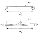
両ロアリンクアーム8、9のみを、その厚み及び幅を誇張した図4(a)、図4(b)、及びロアリンクアーム8、9の動きを表す図5(a)、図5(b)に良く示すように、ロアリンクアーム8、9は上下方向には比較的剛性が高く、かつ左右方向には比較的撓みやすい板ばね状部材からなる。また、ロアリンクアーム8、9のトーションバー10側(一端側)の板厚D1に比較して反トーションバー側(他端側)即ちフレーム1、2側の板厚D2の方が薄くなっていると共にその間のフレーム1、2側(他端側)寄りにフレーム1、2側の板厚D2よりも更に薄い板厚D3の部分が形成され、それら各部の板厚がなだらかに変化している(図4(b))。
【0015】
ここで、両リンクアーム8、9の連結部間の長さをL1としたときに、トーションバー10側の板厚D1は、2.75〜3.25×10⁻²×L1の範囲、フレーム1、2側の板厚D2は、1.5〜2.0×10⁻²×L1の範囲、フレーム1、2寄りの最も板厚の薄い部分の板厚D3は、0.85〜2.75×10⁻²×L1の範囲、にそれぞれなっている。トーションバー10側の板厚D1が2.75×10⁻²×L1よりも、フレーム1、2側の板厚D2が1.5×10⁻²×L1よりも、最も板厚の薄い部分の板厚D3が0.85×10⁻²×L1よりも、それぞれ薄いとその強度を確保できず、トーションバー10側の板厚D1が3.25×10⁻²×L1よりも厚いと不必要に重量化する。
【0016】
また、両リンクアーム8、9の連結部間の長さをL1とし、リンクアーム8、9の最も板厚の薄い部分(板厚D3の部分)のフレーム1、2側の支持部からの距離をL2としたときに、L2/L1=0.25〜0.35の範囲となっている。この範囲を外れると最大発生応力が増大する。図6はD1=3.07×10−2×L1とし、D2=1.73×10−2×L1とし、D3=1.15×10−2×L1としたときのL2/L1、即ち板厚がD3の部分の位置と最大発生応力との関係を示すグラフである。
【0017】
尚、本構成ではリンクアーム8、9の材質として、ブッシュのカラー及びトーションバー10を溶接することから、通常のばね鋼SUP9、9Aでは、溶接割れが発生してしまうため、溶接後、熱処理して上記ばね鋼と同じ硬さの出せるSCM425を使用したが、例えばフレーム1、2側の板厚D2を1.15×10⁻²×L1、トーションバー10側の板厚D1を3.07×10⁻²×L1としてなだらかに変化させてもフレーム1、2側の溶接部の応力が、435(Mpa)より大きくなるため、フレーム1、2側の板厚D2を1.73×10⁻²×L以上に設定した。実際にはその材料によってフレーム1、2側の板厚D2を更に薄くすることも可能であることは云うまでもない。
【0018】
このような構成では図5(a)、図5(b)に示すように、車輪Tからの上下方向の入力ではロアリンクアーム8、9は殆ど変形せず、トーションバー10のねじれにより左右のロアリンクアーム8、9が相対回動して変位を得る(上下方向ばね定数はトーションバー10のねじれにより発生する)。また、左右方向の入力(車体とアクスルとの間の左右ずれ)に対しては、ロアリンクアーム8、9が或る程度撓んでこれを吸収するようになっている。
【0019】
以下に、本実施形態の作動要領について説明する。まず、左右の両車輪Tに同相の上下入力があった場合、空気ばね15、16が上下に撓む。そしてラテラルロッド19のフレーム1側の支点を中心に、アクスル7の軌跡がラテラルロッド19の支持点間距離を半径とする弧を描くので、車体とアクスル7との間の左右ずれが生じる。これに対してアッパーリンクアーム3、4は、その両端でブッシュを介して支持されているため、このずれに追随する。また、ロアリンクアーム8、9は上記したように板ばね状部材をなすことから、左右に容易に撓むことができ、アクスル7との連結端はこのずれに追随できる。従って、ばね下部分が上下動し易くなり、車体フレーム側への振動伝達量を低減できる。尚、首部10a、10bには段差があるため、ブッシュ13、14とトーションバー10との間で左右ずれが生じることはない。
【0020】
次に、左右両車輪Tに逆相の入力があった場合、ラテラルロッド19のフレーム1側の支点を中心に、アクスル7が傾動し、一方のタイヤは上昇し、他方は下降する。このとき、ロアリンクアーム8、9には、左右撓みが発生し、同時にトーションバー10にねじれが発生する(図5(a)及び図5(b)参照)。上記と同様にこの左右撓みにより車体フレーム側への振動伝達量を低減できる。尚、上記と同様に首部10a、10bには段差があるため、ブッシュ13、14とトーションバー10との間で左右ずれが生じることはない。
【0021】
更に、左右両車輪Tに横加速度の入力があってロールが発生した場合は、逆相入力時と同様に、ラテラルロッド19のフレーム1側の支点を中心に、車体フレームとアクスル7とが相対的に回転し、ロアリンクアーム8、9には、左右撓みが発生し、同時にトーションバー10にねじれが発生してそれらの反力によりロールを抑制することができる。尚、上記したようにロアリンクアーム8、9は比較的左右に撓み易く設定されていることからその反力も小さく、適度なロールが運転者に伝達されるため、コーナリング時の適正速度を知らせることができるようになっている。尚、上記と同様に首部10a、10bには段差があるため、ブッシュ13、14とトーションバー10との間で左右ずれが生じることはない。
【0022】
図7(a)及び図7(b)は、本発明が適用された第2の実施形態に於けるトラックの従動輪のエアサスペンション装置用スタビライザの要部構成を示す図4(a)及び図4(b)と同様な図である。上記構成では両ロアリンクアーム8、9の板幅(上下の寸法)は一定としたが、本構成では、トーションバー10側の板幅W1に比較してフレーム1、2側の板幅W2の方が狭くなっていると共にその間の板幅がなだらかに変化している。それ以外の構成は上記第1の実施形態と同様である。
【0023】
ここで、両リンクアーム8、9の連結部間の長さをL1としたときに、トーションバー10側の板幅W1が0.325〜0.375×L1の範囲に、フレーム1、2側の板幅W2が0.25〜0.30×L1の範囲にそれぞれなっており、かつW1/W2=1.1〜1.5の範囲となっている。トーションバー10側の板幅W1が0.325×L1よりも狭く、フレーム1、2側の板幅W2が0.25〜0.30×L1よりも狭いとその強度を確保できず、トーションバー10側の板幅W1が3.25×10−2×L1よりも広いと不必要に大型化・重量化する。また、W1/W2が1.1よりも小さくなるとトーションバー10側の応力が急激に増大し、1.5よりも大きくなると、フレーム1、2側の応力が急激に増大することで最大発生応力が増大する。図8はD1=3.07×10−2×L1とし、D2=1.73×10−2×L1とし、D3=1.15×10−2×L1とし、L2/L1=0.3としたときのW1/W2と最大発生応力との関係を示すグラフである。
【0024】
尚、上記各実施形態ではロアリンクアーム8、9の一端同士をトーションバー10で一体的に剛結し、これでアクスル7を支持し、ロアリンクアーム8、9の各他端をフレーム1、2に枢着したが、図9に示すように、トーションバー10をフレーム1、2に枢着し、ロアリンクアーム8、9の各他端でアクスル7を支持しても良い。また、アッパーリンクアームに代えてアクスルハウジングの中心部とフレーム1、2との間にV字ロッドを介在させ、これとロアリンクアーム8、9とにより平行リンクが構成し、アクスルハウジングとフレーム1、2との間に左右各一対の空気ばねを設ける構成としても良い。
【0025】
【発明の効果】
上記した説明により明らかなように、本発明によるエアサスペンション装置用スタビライザによれば、両リンクアームに於けるトーションバー側の板厚に比較して反トーションバー側の板厚を薄くすると共にその間の反トーションバー側寄りに反トーションバー側の板厚よりも更に薄い部分を形成し、各部の板厚をなだらかに変化させることで、リンクアームの各部への応力集中を防止し、最大発生応力を低減し、耐久性を向上することができる。また、両リンクアームに於けるトーションバー側の板幅に比較して反トーションバー側の板幅を狭くすると共にその間の板幅をなだらかに変化させることで、最大発生応力低減効果が一層高くなる。
【図面の簡単な説明】
【図1】 本発明が適用された第1の実施形態に於けるトラックの従動輪のサスペンション装置の概略構成を示す平面図。
【図2】 図1に示したサスペンション装置の側面図。
【図3】 図1に示したサスペンション装置の要部底面図。
【図4】 (a)はリンクアームのみの平面図、(b)はその側面図。
【図5】 (a)は本発明によるエアサスペンション装置の作動を説明するロアリンクアームの側面図、(b)はその底面図。
【図6】 リンクアームの最も板厚の薄い部分の位置と最大発生応力との関係を示すグラフ。
【図7】 本発明が適用された第2の実施形態に於けるトラックの従動輪のサスペンション装置のリンクアームのみの平面図、(b)はその側面図。
【図8】 W1(トーションバー側の板幅)/W2(トーションバーと相反する側板幅)と最大発生応力との関係を示すグラフ。
【図9】 本発明の応用例を示す図3と同様な図。
【符号の説明】
1、2 車体フレーム
3、4 アッパーリンクアーム
5、6 ブラケット
7 アクスル
8、9 ロアリンクアーム
10 トーションバー
10a、10b 首部
11、12 ブッシュ
13、14 ブッシュ
15、16 空気ばね
17、18 ショックアブソーバ
19 ラテラルロッド
T 車輪[0001]
BACKGROUND OF THE INVENTION
The present invention relates to a stabilizer for an air suspension device that is suitable for use in large trucks, buses, and the like and has a pair of left and right link arms that extend parallel to each other in the vehicle longitudinal direction so as to connect a vehicle body frame and an axle. .
[0002]
[Prior art]
2. Description of the Related Art Conventionally, axle suspension devices used for large trucks, buses, and the like have been known that use air springs that have improved riding comfort and the like compared to those that use leaf springs. This air spring, when used alone, basically has two points of action and has no width or length. Therefore, unlike a leaf spring, the air spring cannot be connected in the front / rear / left / right direction. Etc. need to be used together. For this purpose, for example, a pair of left and right link arms extending in parallel with each other in the vehicle longitudinal direction to connect the vehicle body frame and the axle, and a similar pair of link arms or a V-shaped rod-shaped link arm on the upper side thereof. There is a parallel link type provided. In the case of providing two pairs of link arms, it is common to provide a lateral rod for connecting the vehicle body frame and the axle .
[0003]
In the suspension device as described above, a stabilizer is often provided separately for suppressing the swing of the left and right wheels, but the weight of this stabilizer is heavy, 20 kg to 30 kg, which has led to an increase in the weight of the vehicle body. .
[0004]
To cope with such an inconvenience, the present the same applicant, in the Pat. Laid Application flat 9-223784, the left and right link arms of the air suspension device, easily bent leaf spring in the lateral direction than the vertical direction formed with Jo members, connected by a torsion bar extending the one ends in the lateral direction, and connecting the other to the axle with one of the other ends and the torsion bar is connected to the vehicle body side, and link arms It proposes to configure suppressing stabilizer sway left and right wheels by the torsion bars.
[0005]
According to this structure, the stabilizer hanger bracket used for supporting the separate stabilizer and the stabilizer on the vehicle body frame is omitted, the vehicle weight is reduced, the number of parts is reduced, and the vehicle cost is reduced.
[0006]
[Problems to be solved by the invention]
At a link arm of the configuration information, the torsion bar side is rigidly connected, such as the anti-torsion bar side is supported via a bushing, of the difference or the support structure of the movable range in the torsion bar side and anti torsion bar side Because there is a difference , it is easier to adjust the spring constant by using a so-called taper leaf with a plate thickness on the anti-torsion bar side thinner than the plate thickness on the torsion bar side, and the maximum generation of the link arm when bending in the left-right direction Stress can be reduced . On the other hand, if the plate thickness on the anti-torsion bar side is made too thin, the strength of that portion will decrease , and conversely, if the plate thickness on the torsion bar side is increased while securing the plate thickness on the anti-torsion bar side , the link arm will device becomes too thick that occur is a problem that the large size and weight reduction.
[0007]
The present invention has been made in view of such problems of the prior art, and its purpose is to maximize the generation of link arms without causing a partial decrease in strength, and without increasing the size and weight. An object of the present invention is to provide a stabilizer for an air suspension device that can reduce stress and improve durability.
[0008]
[Means for Solving the Problems]
The above-described purpose is a pair of left and
[0009]
Further, the two link arms, that between the plate width with is narrower towards the comparison to the other end of the plate width to plate width of the one end side is changing smoothly, the maximum stress reduction The effect becomes even higher. In that case, the length between coupling portions of the link arms is taken as
[0010]
DETAILED DESCRIPTION OF THE INVENTION
Hereinafter, preferred embodiments of the present invention will be described in detail with reference to the accompanying drawings.
[0011]
1 to 3 show a schematic configuration of an air suspension device for a driven wheel of a truck in a first embodiment to which the present invention is applied. This suspension device is an axle type suspension device using an air spring. One end of a pair of
[0012]
As shown well in FIGS. 2 and 3,
[0014]
Both
[0015]
Here, the length between coupling portions of the
[0016]
Further, the length between coupling portions of the
[0017]
As the material of the
[0018]
In such a configuration, as shown in FIGS. 5A and 5B , the
[0019]
Below, the operation | movement point of this embodiment is demonstrated. First, when there is an in-phase up / down input to the left and right wheels T, the air springs 15 and 16 bend up and down. And around the fulcrum of the
[0020]
Then, when there is a reverse phase input to the left and right wheels T, around the fulcrum of the
[0021]
Further, when a lateral acceleration is input to both the left and right wheels T and a roll is generated, the vehicle body frame and the
[0022]
FIGS. 7 (a) and 7 (b), 4 (a) and illustrates a main configuration of the air suspension device for a stabilizer of the driven wheels in the track to a second embodiment of the present invention is applied It is the same figure as 4 (b). In the above configuration, the plate widths (vertical dimensions) of the
[0023]
Here, the length between coupling portions of the
[0024]
In each of the above embodiments and rigidly connected integrally to one ends of the
[0025]
【The invention's effect】
As is clear from the above description, according to the stabilizer for an air suspension device according to the present invention, the plate thickness on the anti-torsion bar side is made thinner than the plate thickness on the torsion bar side in both link arms. A portion thinner than the plate thickness on the anti-torsion bar side is formed near the anti-torsion bar side, and the thickness of each part is changed gently to prevent stress concentration on each part of the link arm, and the maximum generated stress It can reduce and improve durability. In addition, by reducing the plate width on the anti-torsion bar side compared with the plate width on the torsion bar side in both link arms and gently changing the plate width between them, the effect of reducing the maximum generated stress is further enhanced. .
[Brief description of the drawings]
FIG. 1 is a plan view showing a schematic configuration of a suspension device for a driven wheel of a track in a first embodiment to which the present invention is applied.
FIG. 2 is a side view of the suspension device shown in FIG.
FIG. 3 is a bottom view of the main part of the suspension device shown in FIG. 1;
4A is a plan view of only a link arm, and FIG. 4B is a side view thereof.
5A is a side view of a lower link arm for explaining the operation of the air suspension device according to the present invention, and FIG. 5B is a bottom view thereof.
FIG. 6 is a graph showing the relationship between the position of the thinnest part of the link arm and the maximum generated stress.
FIG. 7 is a plan view of only a link arm of a suspension device for a driven wheel of a track in a second embodiment to which the present invention is applied, and (b) is a side view thereof.
FIG. 8 is a graph showing the relationship between W1 (plate width on the torsion bar side) / W2 (side plate width opposite to the torsion bar) and maximum generated stress.
FIG. 9 is a view similar to FIG. 3 showing an application example of the present invention.
[Explanation of symbols]
1, 2
Claims (5)
前記両リンクアームが、前記一端側の板厚に比較して前記他端側の板厚の方が薄くなっていると共にその間の前記他端側寄りに前記他端側の板厚よりも更に薄い部分を有し、且つ各部の板厚がなだらかに変化していることを特徴とするエアサスペンション装置用スタビライザ。 A pair of left and right link arms that are parallel to each other in the longitudinal direction of the vehicle and that connect the vehicle body frame and the axle, and are connected to one end of each of the link arms. A torsion bar extending in the left-right direction, and either one of the other ends of the link arms and the torsion bar is coupled to the body frame side via a rubber bush or a ball joint, and the other is a rubber A stabilizer for an air suspension device for suppressing swinging of right and left wheels by being coupled to the axle via a bush or a ball joint ,
The link arms are thinner than the other end of the plate thickness during the other end closer together compared to the thickness of the one end side are thinner is better for the thickness of the other end A stabilizer for an air suspension device, characterized in that the plate has portions and the thickness of each portion changes gently.
Priority Applications (1)
| Application Number | Priority Date | Filing Date | Title |
|---|---|---|---|
| JP3563799A JP3773685B2 (en) | 1999-02-15 | 1999-02-15 | Stabilizer for air suspension system |
Applications Claiming Priority (1)
| Application Number | Priority Date | Filing Date | Title |
|---|---|---|---|
| JP3563799A JP3773685B2 (en) | 1999-02-15 | 1999-02-15 | Stabilizer for air suspension system |
Publications (3)
| Publication Number | Publication Date |
|---|---|
| JP2000233621A JP2000233621A (en) | 2000-08-29 |
| JP2000233621A5 JP2000233621A5 (en) | 2004-09-30 |
| JP3773685B2 true JP3773685B2 (en) | 2006-05-10 |
Family
ID=12447405
Family Applications (1)
| Application Number | Title | Priority Date | Filing Date |
|---|---|---|---|
| JP3563799A Expired - Lifetime JP3773685B2 (en) | 1999-02-15 | 1999-02-15 | Stabilizer for air suspension system |
Country Status (1)
| Country | Link |
|---|---|
| JP (1) | JP3773685B2 (en) |
Families Citing this family (8)
| Publication number | Priority date | Publication date | Assignee | Title |
|---|---|---|---|---|
| JP2002187418A (en) * | 2000-12-19 | 2002-07-02 | Nhk Spring Co Ltd | Suspension |
| DE102004020050A1 (en) * | 2004-04-23 | 2005-11-24 | Daimlerchrysler Ag | rear axle |
| FR2986995B1 (en) * | 2012-02-20 | 2015-04-24 | Colaert Essieux | SUSPENSION FOR TRANSPORT VEHICLE |
| US9085212B2 (en) | 2013-03-15 | 2015-07-21 | Hendrickson Usa, L.L.C. | Vehicle suspension |
| US9150071B2 (en) | 2013-07-25 | 2015-10-06 | Hendrickson Usa, L.L.C. | Frame hanger for vehicle suspension |
| US9315083B2 (en) | 2014-07-15 | 2016-04-19 | Hendrickson Usa, L.L.C. | Frame hanger for providing thrust angle alignment in vehicle suspension |
| CN113650467B (en) * | 2021-08-26 | 2023-01-06 | 安庆汇通汽车部件股份有限公司 | Adjustable composite stabilizer bar and assembly method thereof |
| KR102606916B1 (en) * | 2022-01-20 | 2023-11-29 | 서한이노빌리티(주) | a shock absorber for a vehicle |
-
1999
- 1999-02-15 JP JP3563799A patent/JP3773685B2/en not_active Expired - Lifetime
Also Published As
| Publication number | Publication date |
|---|---|
| JP2000233621A (en) | 2000-08-29 |
Similar Documents
| Publication | Publication Date | Title |
|---|---|---|
| JP2008540201A (en) | Wishbon-type linkage components and suspensions incorporating them | |
| JP4449708B2 (en) | Wheel suspension | |
| JP2002508727A (en) | Double trailing arm type vehicle suspension system | |
| CN107074051B (en) | Wheel suspension with centrally pivoted transverse leaf spring | |
| JP2013209076A (en) | Independent suspending type suspension device | |
| JP3773685B2 (en) | Stabilizer for air suspension system | |
| US20220314721A1 (en) | Automobile suspension device | |
| JP4893429B2 (en) | Suspension device | |
| JP4888189B2 (en) | Suspension device | |
| JP2000233621A5 (en) | ||
| JP2017165319A (en) | Double wishbone type suspension device | |
| JP2004098874A (en) | Stabilizer and air leaf suspension using the same | |
| JP2006192932A (en) | Rear suspension device of automobile | |
| JPH1159154A (en) | Air suspension device | |
| US20220219503A1 (en) | Rear axle for a two-track vehicle and two-track vehicle with a rear axle | |
| JP4529737B2 (en) | Trailing arm structure | |
| JP4998115B2 (en) | Suspension device | |
| JP5056366B2 (en) | Suspension device | |
| JP3669639B2 (en) | Vehicle suspension system | |
| JP3975572B2 (en) | Car suspension equipment | |
| JP2000515460A (en) | Axle suspension for rigid axle of vehicle | |
| JP4534153B2 (en) | Rear suspension device for automobile | |
| JPS6071310A (en) | Trailing link type beam suspension | |
| US11897304B1 (en) | Stabilizer bar support structure of off-road vehicle and off-road vehicle | |
| JP5237872B2 (en) | Vehicle suspension |
Legal Events
| Date | Code | Title | Description |
|---|---|---|---|
| A977 | Report on retrieval |
Free format text: JAPANESE INTERMEDIATE CODE: A971007 Effective date: 20060119 |
|
| TRDD | Decision of grant or rejection written | ||
| A01 | Written decision to grant a patent or to grant a registration (utility model) |
Free format text: JAPANESE INTERMEDIATE CODE: A01 Effective date: 20060207 |
|
| A61 | First payment of annual fees (during grant procedure) |
Free format text: JAPANESE INTERMEDIATE CODE: A61 Effective date: 20060215 |
|
| R150 | Certificate of patent or registration of utility model |
Free format text: JAPANESE INTERMEDIATE CODE: R150 |
|
| FPAY | Renewal fee payment (event date is renewal date of database) |
Free format text: PAYMENT UNTIL: 20100224 Year of fee payment: 4 |
|
| FPAY | Renewal fee payment (event date is renewal date of database) |
Free format text: PAYMENT UNTIL: 20100224 Year of fee payment: 4 |
|
| S533 | Written request for registration of change of name |
Free format text: JAPANESE INTERMEDIATE CODE: R313533 |
|
| FPAY | Renewal fee payment (event date is renewal date of database) |
Free format text: PAYMENT UNTIL: 20100224 Year of fee payment: 4 |
|
| R350 | Written notification of registration of transfer |
Free format text: JAPANESE INTERMEDIATE CODE: R350 |
|
| FPAY | Renewal fee payment (event date is renewal date of database) |
Free format text: PAYMENT UNTIL: 20100224 Year of fee payment: 4 |
|
| FPAY | Renewal fee payment (event date is renewal date of database) |
Free format text: PAYMENT UNTIL: 20110224 Year of fee payment: 5 |
|
| FPAY | Renewal fee payment (event date is renewal date of database) |
Free format text: PAYMENT UNTIL: 20120224 Year of fee payment: 6 |
|
| FPAY | Renewal fee payment (event date is renewal date of database) |
Free format text: PAYMENT UNTIL: 20120224 Year of fee payment: 6 |
|
| FPAY | Renewal fee payment (event date is renewal date of database) |
Free format text: PAYMENT UNTIL: 20130224 Year of fee payment: 7 |
|
| FPAY | Renewal fee payment (event date is renewal date of database) |
Free format text: PAYMENT UNTIL: 20140224 Year of fee payment: 8 |
|
| R250 | Receipt of annual fees |
Free format text: JAPANESE INTERMEDIATE CODE: R250 |
|
| R250 | Receipt of annual fees |
Free format text: JAPANESE INTERMEDIATE CODE: R250 |
|
| R250 | Receipt of annual fees |
Free format text: JAPANESE INTERMEDIATE CODE: R250 |
|
| R250 | Receipt of annual fees |
Free format text: JAPANESE INTERMEDIATE CODE: R250 |
|
| R250 | Receipt of annual fees |
Free format text: JAPANESE INTERMEDIATE CODE: R250 |
|
| EXPY | Cancellation because of completion of term |