JP3772802B2 - Volume setting operator drive device - Google Patents
Volume setting operator drive device Download PDFInfo
- Publication number
- JP3772802B2 JP3772802B2 JP2002192898A JP2002192898A JP3772802B2 JP 3772802 B2 JP3772802 B2 JP 3772802B2 JP 2002192898 A JP2002192898 A JP 2002192898A JP 2002192898 A JP2002192898 A JP 2002192898A JP 3772802 B2 JP3772802 B2 JP 3772802B2
- Authority
- JP
- Japan
- Prior art keywords
- fader
- operator
- volume setting
- dca
- gain
- Prior art date
- Legal status (The legal status is an assumption and is not a legal conclusion. Google has not performed a legal analysis and makes no representation as to the accuracy of the status listed.)
- Expired - Fee Related
Links
Images


Classifications
-
- H—ELECTRICITY
- H04—ELECTRIC COMMUNICATION TECHNIQUE
- H04H—BROADCAST COMMUNICATION
- H04H60/00—Arrangements for broadcast applications with a direct linking to broadcast information or broadcast space-time; Broadcast-related systems
- H04H60/02—Arrangements for generating broadcast information; Arrangements for generating broadcast-related information with a direct linking to broadcast information or to broadcast space-time; Arrangements for simultaneous generation of broadcast information and broadcast-related information
- H04H60/04—Studio equipment; Interconnection of studios
Description
【0001】
【発明の属する技術分野】
本発明は、音声信号のミキサ装置に用いて好適な音量設定操作子の駆動装置に関する。
【0002】
【従来の技術】
コンサート等で用いられるミキサ装置においては、複数の入力チャンネルの音声信号がミキシングされることによって最終的に必要な音声信号が得られる。そして、これら入力チャンネルの各音声信号のゲインは、ミキシングされる前に、複数段階に渡って調節される。例えば、ミキサ装置に入力された直後の音声信号は、ヘッダアンプによってゲイン調節が行われる。このゲイン調節のためには、ボリューム操作子が多用されている。次に、必要に応じて周波数特性のイコライジングが行われた後、フェーダアンプによるゲイン調節が行われる。このフェーダアンプのゲインは各入力チャンネル毎に設けられた入力フェーダによって設定される。
【0003】
また、複数の入力チャンネルに対して、各入力フェーダとは別の共通のフェーダが割り当てられる場合がある。この共通のフェーダは、デジタルミキサにおいては、DCA(Ditigal Controlled Amplifier または Ditigal Controlled Attenuator )フェーダと呼ばれる(アナログミキサの場合はVCA(Voltage Controlled Amplifier または Voltage Controlled Attenuator)フェーダと呼ばれる)。DCAフェーダによって設定されたゲインは、各入力フェーダによって設定されたゲインに乗算され、これによって該複数の入力チャンネルのゲインが決定される。DCAフェーダは、ピアノ、ドラムなどの大型の楽器や、例えばオーケストラの一部のパートの集音と音量制御に用いられる。
【0004】
ピアノ等、大型の楽器の演奏音は複数本のマイクを用いて集音することが一般的である。これら複数のマイクはバランス調節を行うために各々個別の入力チャンネルに割り当てられる。そして、これら入力チャンネルが一のDCAフェーダに割り当てられる。そして、個々のマイクから集音された音声信号相互間のバランスは各入力フェーダによって調節され、楽器全体としての音量はDCAフェーダによって調節されるのである。
【0005】
【発明が解決しようとする課題】
ところで、入力フェーダおよびDCAフェーダは、所定の基準位置(例えば「0dB」の目盛位置)において、ほぼ適切な音量が得られるように事前に調節されていることが望ましい。これにより、ある入力チャンネルをフェードインする時は、オペレータは単にフェーダを基準位置付近に動かせばよく、その後に実際の音量を聞きながらフェーダ位置を微調節すればよいからである。フェーダの基準位置における音量調節は例えばリハーサル時において行われる。しかし、ゲインを一定にしつつフェーダを基準位置に移動するためには、フェーダを動かすと同時にヘッダアンプ用のボリューム操作子または他のフェーダを動かす等の作業が必要であり、非常に煩雑であった。
この発明は上述した事情に鑑みてなされたものであり、フェーダ等の基準位置合わせを迅速かつ正確に行うことができる音量設定操作子の駆動装置を提供することを目的としている。
【0006】
【課題を解決するための手段】
上記課題を解決するため本発明にあっては、下記構成を具備することを特徴とする。なお、括弧内は例示である。
請求項1記載の音量設定操作子の駆動装置にあっては、所定の音声信号のゲイン調節のために設けられ、自動的に駆動可能な第1の音量設定操作子(DCAフェーダ操作子127−1)と、前記第1の音量設定操作子に対応して設けられた位置設定操作子(ノミナル・アジャスト・スイッチ128−1)と、自動的に駆動可能であって、前記第1の音量設定操作子の操作位置ととともに前記音声信号のゲインを決定するために設けられた第2の音量設定操作子(フェーダ操作子124−1〜124−3)と、前記位置設定操作子が操作されると、前記第1の音量設定操作子の操作位置を所定の基準位置に設定するとともに、前記位置設定操作子の操作前におけるゲインを保持する位置に前記第2の音量設定操作子の操作位置を設定する制御手段(CPU2)とを有することを特徴とする。
さらに、請求項2記載の構成にあっては、請求項1記載の音量設定操作子の駆動装置において、前記第2の音量設定操作子は、複数チャンネルの音声信号に応じて複数設けられ、前記制御手段は、前記位置設定操作子の操作前における各音声信号のゲインを保持する位置に、前記複数の第2の音量設定操作子の操作位置を各々設定することを特徴とする。
【0007】
【発明の実施の形態】
1.実施形態の構成
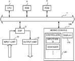
次に、本発明の一実施形態のミキサ装置のハードウエア構成を図1を参照し説明する。
図において2はCPUであり、ROM6に記憶された制御プログラムに基づいて、バス7を介して各部を制御する。10は入力部であり、マイク等から集音したアナログ音声信号をデジタル音声信号に変換するADコンバータ等から構成されている。8はDSPであり、入力部10を介して供給されたデジタル音声信号のミキシング処理、イコライジング処理等を行う。なお、DSP8におけるミキシングアルゴリズムは、CPU2によって設定される。12は出力ユニットであり、DSP8から供給されたデジタル音声信号をアナログ音声信号に変換し出力する。
【0008】
100はミキシングコンソールであり、オペレータによって操作される操作子群120と、オペレータに対して各種情報を表示する表示器110とから構成されている。操作子群120内に設けられた各操作子の操作位置はデジタル的に検出され、CPU2に伝送される。これにより、CPU2によって、各操作子の状態に応じたアルゴリズムがDSP8に対して設定される。さらに、これら各操作子は何れもモータあるいはアクチュエータ等によって自動的に駆動可能になっており、CPU2からの指令に応じてこれらの操作位置を自動的に設定することも可能である。
【0009】
次に、DSP8内において実行されるミキシングアルゴリズムの要部の構成を図2に示す。図においてIN1〜INnは各入力チャンネルにおける入力信号であり、上記入力部10を介して供給される。32−1〜32−nはヘッダアンプ部であり、これら各入力信号IN1〜INnを指定されたゲインで増幅する。34−1〜34−nはフェーダアンプ部であり、ヘッダアンプ部32−1〜32−nを介してゲイン調節された入力信号IN1〜INnに対してさらにゲイン調節を行う。
【0010】
37−1〜37−mは「m」系統のDCAゲイン調節部である。DCAゲイン調節部37−p(1≦p≦k)には、最大「k」チャンネルの音声信号を共通のゲインで増幅するDCAアンプ部37−p−1〜37−p−kが設けられている。35はDCAアサイナであり、各フェーダアンプ部34−1〜34−nから出力された任意の音声信号を任意のDCAゲイン調節部37−1〜37−mにおける任意のチャンネルに割り当てる。これにより、何れのDCAアンプ部にも割り当てられなかった入力チャンネルの音声信号はヘッダアンプ部およびフェーダアンプ部を介して合計2回ゲイン調節され、何れかのDCAアンプ部に割り当てらた入力チャンネルの音声信号は合計3回ゲイン調節される。このようにゲイン調節された音声信号は後段のミキシングバス(図示せず)を介してミキシングされる。
【0011】
次に、操作子群120の要部の外観図を図3に示す。図において122−1〜122−nはボリューム操作子であり、その操作位置によって対応するヘッダアンプ部32−1〜32−nのゲインが設定される。また、124−1〜124−nはフェーダ操作子であり、その操作位置によって対応するフェーダアンプ部34−1〜34−nのゲインが設定される。126−1〜126−nはノミナル・アジャスト・スイッチであり、対応するフェーダ操作子124−1〜124−nの操作位置を基準位置(0dB)に自動設定するために設けられている。
【0012】
次に、127−1,127−2,……はDCAフェーダ操作子であり、その操作位置によって対応するDCAゲイン調節部37−1〜37−mにおける共通ゲインが設定される。128−1,128−2,……はDCA用のノミナル・アジャスト・スイッチであり、対応するDCAフェーダ操作子127−1,127−2,……の操作位置を基準位置(0dB)に自動設定するために設けられている。
【0013】
2.実施形態の動作
次に、本実施形態の動作を説明する。
まず、DCA用のノミナル・アジャスト・スイッチ128−j(1≦j≦m)の押下イベントが発生すると、図4(a)に示すイベント処理ルーチンが実行される。図において処理がステップSP2に進むと、DCAフェーダ操作子127−jの操作位置の設定値DCAjが取得される。次に、処理がステップSP4に進むと、該設定値DCAjが「0dB」以外の値であるか否かが確認される。ここで「NO」と判定されると、実質的な処理が行われないまま本ルーチンの処理が終了する。
【0014】
一方、ステップSP4において「YES」と判定されると、処理はステップSP6に進み、DCAフェーダ操作子127−jにアサインされている全てのフェーダ操作子に対する操作位置の現在設定値に対して、上記確認された設定値DCAjが加算されるとともに、DCAフェーダ操作子127−jの操作位置の設定値DCAj自体は「0dB」に設定される。以上により、本ルーチンの処理が終了する。ここで、図3を再び参照し、上記ルーチンの動作の具体例を説明しておく。
【0015】
まず、フェーダ操作子のうち124−1〜124−3がDCAフェーダ操作子127−1に割り当てられ、124−(n−1),124−nがDCAフェーダ操作子127−2に割り当てられているとする。ここで、フェーダ操作子124−1〜124−3の操作位置が各々「−50dB」,「−30dB」,「−60dB」(図上では下側の一点鎖線)であってDCAフェーダ操作子127−1の設定値が「−20dB」であったとする(図上では一点鎖線)。
【0016】
ここで、スイッチ128−1が押下されると、上記ステップSP6によればフェーダ操作子124−1〜124−3の操作位置の設定値に各々「−20dB」が加算されるから、これらの操作位置の設定値は各々「−70dB」,「−50dB」,「−80dB」に変更される。さらに、これに伴って、DCAフェーダ操作子127−1の操作位置の設定値は「0dB」(図上では何れも実線)に変更される。そして、これらフェーダ操作子は、各操作位置が各設定値に一致するように自動的に駆動される。
【0017】
同様に、フェーダ操作子のうち124−(n−1),124−nの操作位置が各々「−50dB」,「−20dB」(図上では下側の一点鎖線)であってDCAフェーダ操作子127−2の操作位置が「+10dB」であったとする。ここで、スイッチ128−2が押下されると、フェーダ操作子124−(n−1),124−nの操作位置の設定値に各々「+10dB」が加算されるから、これらの設定値は各々「−40dB」,「−10dB」に自動的に変更される。さらに、これに伴って、DCAフェーダ操作子127−2の操作位置の設定値は「0dB」(図上では何れも実線)に変更される。そして、これらフェーダ操作子についても、各操作位置が各設定値に一致するように自動的に駆動される。
【0018】
次に、入力チャンネル用のノミナル・アジャスト・スイッチ126−i(1≦i≦n)の押下イベントが発生すると、図4(b)に示すイベント処理ルーチンが実行される。図において処理がステップSP22に進むと、フェーダ操作子124−iの操作量の設定値INiが取得される。次に、処理がステップSP24に進むと、該設定値INiが「0dB」以外の値であるか否かが確認される。ここで「NO」と判定されると、実質的な処理が行われないまま本ルーチンの処理が終了する。
【0019】
一方、ステップSP24において「YES」と判定されると、処理はステップSP26に進み、ボリューム操作子122−iの操作位置の現在の設定値に対して、上記確認された設定値INiが加算されるとともに、設定値INi自体は「0dB」に設定される。以上により、本ルーチンの処理が終了する。ここで、図3を再び参照し、上記ルーチンの動作の具体例を説明しておく。
【0020】
まず、フェーダ操作子124−1の設定値が「−70dB」(実線)であって、ボリューム操作子122−1の設定値が「+40dB」であったとする。ここで、ノミナル・アジャスト・スイッチ126−1が押下されると、上記ステップSP26によればボリューム操作子122−1の設定値に「−70dB」が加算されるから、この設定値は各々「−30dB」に変更される。さらに、これに伴って、フェーダ操作子124−1は「0dB」(図上では上側の一点鎖線)に変更される。そして、これらボリューム操作子122−1およびノミナル・アジャスト・スイッチ126−1についても、各操作位置が各設定値に一致するように自動的に駆動される。
【0021】
他のノミナル・アジャスト・スイッチ126−2〜126−nについても同様であり、これらを押下しておくことにより、各フェーダ操作子の設定値は基準位置「0dB」に揃えられ、それに応じて対応するボリューム操作子122−iの設定値が増減されることになる。以上のように本実施形態によれば、ノミナル・アジャスト・スイッチを単に押下することによって、対応するフェーダ操作子の設定位置を自動的に基準位置に設定することができる。
【0022】
3.変形例
本発明は上述した実施形態に限定されるものではなく、例えば以下のように種々の変形が可能である。
(1)上記実施形態のステップSP6においては、ノミナル・アジャスト・スイッチ128−jが押下されると、対応するDCAフェーダ操作子127−jに割り当てられた入力チャンネルに係るフェーダ操作子124−1〜124−nの設定値が変更された。しかし、ステップSP6においては、フェーダ操作子124−1〜124−nに代えて、ボリューム操作子122−1〜122−nの設定値を変更するようにしてもよい。
【0023】
(2)また、上記実施形態においては、ミキシングアルゴリズムをDSP8において実行するデジタルミキサ装置に本発明を適用した例を説明したが、本発明はデジタルミキサ装置に限定されるものではない。すなわち、各ボリューム操作子およびフェーダ操作子が可変抵抗器に直結され該可変抵抗器によって音声信号のゲインが直接的に設定されるアナログミキサ装置においても、これらボリューム操作子およびフェーダ操作子を自動的に駆動することができれば本発明を適用することが可能である。
【0024】
【発明の効果】
以上説明したように本発明によれば、位置設定操作子が操作されると、第1の音量設定操作子が自動的に基準位置に設定されるとともに、操作前のゲインを保持する位置に第2の音量設定操作子の操作位置が設定されるから、第1の音量設定操作子の基準位置合わせを迅速かつ正確に行うことができる。
【図面の簡単な説明】
【図1】 本発明の一実施形態のミキサ装置のハードウエアブロック図である。
【図2】 一実施形態のミキサ装置のミキシングアルゴリズムの要部のブロック図である。
【図3】 操作子群120の要部の外観図である。
【図4】 CPU2において実行される制御プログラムのフローチャートである。
【符号の説明】
2…CPU、6…ROM、7…バス、8…DSP、10…入力部、12…出力ユニット、32−1〜32−n…ヘッダアンプ部、34−1〜34−n…フェーダアンプ部、35…DCAアサイナ、37−1〜37−m…DCAゲイン調節部、37−1−1〜37−1−k…DCAアンプ部、37−p−1〜37−p−k…DCAアンプ部、100…ミキシングコンソール、110…表示器、120…操作子群、122−1〜122−n…ボリューム操作子、124−1〜124−n…フェーダ操作子、126−1〜126−n…ノミナル・アジャスト・スイッチ、127−1,127−2,………DCAフェーダ操作子、128−1,128−2,………ノミナル・アジャスト・スイッチ。[0001]
BACKGROUND OF THE INVENTION
The present invention relates to a drive device for a volume setting operator suitable for use in an audio signal mixer device.
[0002]
[Prior art]
In a mixer apparatus used in a concert or the like, necessary audio signals are finally obtained by mixing audio signals of a plurality of input channels. The gains of the audio signals of these input channels are adjusted in a plurality of stages before being mixed. For example, the gain of the audio signal immediately after being input to the mixer device is adjusted by the header amplifier. For this gain adjustment, a volume operator is frequently used. Next, frequency characteristics are equalized as necessary, and then gain adjustment by a fader amplifier is performed. The gain of this fader amplifier is set by an input fader provided for each input channel.
[0003]
In addition, a common fader different from each input fader may be assigned to a plurality of input channels. This common fader is called a DCA (Ditigal Controlled Attenuator) fader in a digital mixer (in the case of an analog mixer, it is called a VCA (Voltage Controlled Amplifier or Voltage Controlled Attenuator) fader). The gain set by the DCA fader is multiplied by the gain set by each input fader, and thereby the gains of the plurality of input channels are determined. The DCA fader is used for sound collection and volume control of a large musical instrument such as a piano or a drum, or a part of an orchestra, for example.
[0004]
The performance sound of a large musical instrument such as a piano is generally collected using a plurality of microphones. Each of these microphones is assigned to an individual input channel for balance adjustment. These input channels are assigned to one DCA fader. The balance between the audio signals collected from the individual microphones is adjusted by each input fader, and the volume of the entire instrument is adjusted by the DCA fader.
[0005]
[Problems to be solved by the invention]
Incidentally, it is desirable that the input fader and the DCA fader are adjusted in advance so as to obtain a substantially appropriate sound volume at a predetermined reference position (for example, a scale position of “0 dB”). Thus, when fading in an input channel, the operator simply moves the fader to the vicinity of the reference position, and then finely adjusts the fader position while listening to the actual volume. Volume adjustment at the reference position of the fader is performed, for example, during rehearsal. However, in order to move the fader to the reference position while keeping the gain constant, it is necessary to move the fader at the same time as moving the volume control for the header amplifier or other faders. .
The present invention has been made in view of the above-described circumstances, and an object of the present invention is to provide a drive device for a volume setting operator that can quickly and accurately perform reference position adjustment of a fader or the like.
[0006]
[Means for Solving the Problems]
In order to solve the above problems, the present invention is characterized by having the following configuration. The parentheses are examples.
In the drive device for the volume setting operation element according to
Furthermore, in the configuration according to
[0007]
DETAILED DESCRIPTION OF THE INVENTION
1. Configuration of Embodiment Next, a hardware configuration of a mixer apparatus according to an embodiment of the present invention will be described with reference to FIG.
In the figure,
[0008]
[0009]
Next, FIG. 2 shows a configuration of a main part of a mixing algorithm executed in the DSP 8. In the figure, IN1 to INn are input signals in the respective input channels and are supplied via the
[0010]
Reference numerals 37-1 to 37-m denote “m” DCA gain adjusters. The DCA gain adjustment unit 37-p (1 ≦ p ≦ k) is provided with DCA amplifier units 37-p-1 to 37-pk that amplify the audio signal of the maximum “k” channel with a common gain. Yes.
[0011]
Next, the external view of the principal part of the
[0012]
Next, 127-1, 127-2,... Are DCA fader operators, and common gains in the corresponding DCA gain adjusting units 37-1 to 37-m are set according to the operation positions. 128-1, 128-2,... Are DCA nominal adjustment switches, and the corresponding DCA fader operation elements 127-1, 127-2,... Are automatically set to the reference position (0 dB). Is provided to do.
[0013]
2. Operation of Embodiment Next, the operation of this embodiment will be described.
First, when a pressing event of the DCA nominal adjustment switch 128-j (1 ≦ j ≦ m) occurs, the event processing routine shown in FIG. 4A is executed. In the figure, when the process proceeds to step SP2, the setting value DCAj of the operation position of the DCA fader operator 127-j is acquired. Next, when the process proceeds to step SP4, it is confirmed whether or not the set value DCAj is a value other than “0 dB”. If “NO” is determined here, the processing of this routine ends without performing substantial processing.
[0014]
On the other hand, if “YES” is determined in step SP4, the process proceeds to step SP6, and the current setting values of the operation positions for all fader operators assigned to the DCA fader operators 127-j are described above. The confirmed set value DCAj is added, and the set value DCAj of the operation position of the DCA fader operator 127-j itself is set to “0 dB”. Thus, the processing of this routine ends. Here, referring again to FIG. 3, a specific example of the operation of the routine will be described.
[0015]
First, of the fader operators, 124-1 to 124-3 are assigned to the DCA fader operator 127-1, and 124- (n-1) and 124-n are assigned to the DCA fader operator 127-2. And Here, the operation positions of fader operation elements 124-1 to 124-3 are “−50 dB”, “−30 dB”, and “−60 dB” (the lower one-dot chain line in the drawing), respectively, and DCA fader operation element 127. It is assumed that the set value of −1 is “−20 dB” (one-dot chain line in the drawing).
[0016]
Here, when the switch 128-1 is pressed, according to the above-mentioned step SP6, “−20 dB” is added to the set values of the operation positions of the fader operators 124-1 to 124-3. The position setting values are changed to “−70 dB”, “−50 dB”, and “−80 dB”, respectively. Further, along with this, the set value of the operation position of the DCA fader operator 127-1 is changed to “0 dB” (both are solid lines in the figure). These fader operators are automatically driven so that each operation position matches each set value.
[0017]
Similarly, among the fader operators, the operation positions of 124- (n-1) and 124-n are "-50 dB" and "-20 dB" (the lower one-dot chain line in the figure), respectively, and the DCA fader operator Assume that the operation position of 127-2 is “+10 dB”. Here, when the switch 128-2 is pressed, “+10 dB” is added to the set values of the operation positions of the fader operators 124- (n−1) and 124-n, respectively. It is automatically changed to “−40 dB” and “−10 dB”. Further, along with this, the set value of the operation position of the DCA fader operator 127-2 is changed to “0 dB” (both are solid lines in the figure). These fader operators are also automatically driven so that each operation position matches each set value.
[0018]
Next, when a pressing event of the nominal adjust switch 126-i (1 ≦ i ≦ n) for the input channel occurs, the event processing routine shown in FIG. 4B is executed. In the figure, when the process proceeds to step SP22, the setting value INi of the operation amount of the fader operator 124-i is acquired. Next, when the process proceeds to step SP24, it is confirmed whether or not the set value INi is a value other than “0 dB”. If “NO” is determined here, the processing of this routine ends without performing substantial processing.
[0019]
On the other hand, if “YES” is determined in step SP24, the process proceeds to step SP26, and the confirmed setting value INi is added to the current setting value of the operation position of the volume operator 122-i. At the same time, the set value INi itself is set to “0 dB”. Thus, the processing of this routine ends. Here, referring again to FIG. 3, a specific example of the operation of the routine will be described.
[0020]
First, it is assumed that the setting value of fader operator 124-1 is “−70 dB” (solid line) and the setting value of volume operator 122-1 is “+40 dB”. Here, when the nominal adjustment switch 126-1 is pressed, “−70 dB” is added to the set value of the volume operator 122-1 according to the above-mentioned step SP26. 30 dB ". Along with this, fader operator 124-1 is changed to “0 dB” (the upper one-dot chain line in the drawing). The volume operation elements 122-1 and the nominal adjustment switch 126-1 are also automatically driven so that the operation positions coincide with the set values.
[0021]
The same applies to the other nominal adjustment switches 126-2 to 126-n. By depressing these switches, the setting value of each fader operator is aligned to the reference position “0 dB” and correspondingly adjusted accordingly. The set value of the volume operator 122-i to be increased or decreased. As described above, according to this embodiment, the setting position of the corresponding fader operator can be automatically set as the reference position by simply pressing the nominal adjustment switch.
[0022]
3. Modifications The present invention is not limited to the above-described embodiments, and various modifications can be made as follows, for example.
(1) In step SP6 of the above embodiment, when the nominal adjustment switch 128-j is pressed, fader operators 124-1 to 124-1 related to the input channels assigned to the corresponding DCA fader operators 127-j. The set value of 124-n was changed. However, in step SP6, the setting values of the volume operators 122-1 to 122-n may be changed instead of the fader operators 124-1 to 124-n.
[0023]
(2) In the above embodiment, the example in which the present invention is applied to the digital mixer apparatus that executes the mixing algorithm in the DSP 8 has been described. However, the present invention is not limited to the digital mixer apparatus. In other words, even in an analog mixer apparatus in which each volume controller and fader controller are directly connected to a variable resistor and the gain of the audio signal is directly set by the variable resistor, these volume controller and fader operator are automatically set. It is possible to apply the present invention as long as it can be driven.
[0024]
【The invention's effect】
As described above, according to the present invention, when the position setting operation element is operated, the first volume setting operation element is automatically set to the reference position, and the first volume setting operation element is set to the position where the gain before the operation is held. Since the operation position of the second volume setting operator is set, the reference position alignment of the first volume setting operator can be performed quickly and accurately.
[Brief description of the drawings]
FIG. 1 is a hardware block diagram of a mixer apparatus according to an embodiment of the present invention.
FIG. 2 is a block diagram of a main part of a mixing algorithm of the mixer device according to the embodiment.
3 is an external view of a main part of an
FIG. 4 is a flowchart of a control program executed by
[Explanation of symbols]
2 ... CPU, 6 ... ROM, 7 ... bus, 8 ... DSP, 10 ... input unit, 12 ... output unit, 32-1 to 32-n ... header amplifier unit, 34-1 to 34-n ... fader amplifier unit, 35 ... DCA assigner, 37-1 to 37-m ... DCA gain adjusting unit, 37-1-1-1 to 37-1-k ... DCA amplifier unit, 37-p-1 to 37-pk ... DCA amplifier unit, DESCRIPTION OF
Claims (2)
前記第1の音量設定操作子に対応して設けられた位置設定操作子と、
自動的に駆動可能であって、前記第1の音量設定操作子の操作位置ととともに前記音声信号のゲインを決定するために設けられた第2の音量設定操作子と、
前記位置設定操作子が操作されると、前記第1の音量設定操作子の操作位置を所定の基準位置に設定するとともに、前記位置設定操作子の操作前におけるゲインを保持する位置に前記第2の音量設定操作子の操作位置を設定する制御手段と
を有することを特徴とする音量設定操作子の駆動装置。A first volume setting operator provided for adjusting the gain of a predetermined audio signal and capable of being automatically driven;
A position setting operator provided corresponding to the first volume setting operator;
A second volume setting operator that is automatically drivable and is provided for determining a gain of the audio signal together with an operation position of the first volume setting operator;
When the position setting operator is operated, the operation position of the first volume setting operator is set to a predetermined reference position, and the second position is held at a position where the gain before the operation of the position setting operator is held. And a control means for setting the operation position of the volume setting operator.
前記制御手段は、前記位置設定操作子の操作前における各音声信号のゲインを保持する位置に、前記複数の第2の音量設定操作子の操作位置を各々設定することを特徴とする請求項1記載の音量設定操作子の駆動装置。A plurality of the second volume setting operators are provided according to a plurality of channels of audio signals,
The control means sets the operation position of each of the plurality of second volume setting operators to a position where the gain of each audio signal before the operation of the position setting operator is held. The drive device of the volume setting operation element described.
Priority Applications (2)
| Application Number | Priority Date | Filing Date | Title |
|---|---|---|---|
| JP2002192898A JP3772802B2 (en) | 2002-07-02 | 2002-07-02 | Volume setting operator drive device |
| US10/608,786 US7539317B2 (en) | 2002-07-02 | 2003-06-26 | Drive apparatus for volume control devices |
Applications Claiming Priority (1)
| Application Number | Priority Date | Filing Date | Title |
|---|---|---|---|
| JP2002192898A JP3772802B2 (en) | 2002-07-02 | 2002-07-02 | Volume setting operator drive device |
Publications (2)
| Publication Number | Publication Date |
|---|---|
| JP2004040347A JP2004040347A (en) | 2004-02-05 |
| JP3772802B2 true JP3772802B2 (en) | 2006-05-10 |
Family
ID=29996985
Family Applications (1)
| Application Number | Title | Priority Date | Filing Date |
|---|---|---|---|
| JP2002192898A Expired - Fee Related JP3772802B2 (en) | 2002-07-02 | 2002-07-02 | Volume setting operator drive device |
Country Status (2)
| Country | Link |
|---|---|
| US (1) | US7539317B2 (en) |
| JP (1) | JP3772802B2 (en) |
Families Citing this family (10)
| Publication number | Priority date | Publication date | Assignee | Title |
|---|---|---|---|---|
| JP4103846B2 (en) * | 2004-04-30 | 2008-06-18 | ソニー株式会社 | Information processing apparatus, volume control method, recording medium, and program |
| JP4765494B2 (en) * | 2005-09-07 | 2011-09-07 | ヤマハ株式会社 | Acoustic signal processing device |
| US8825737B2 (en) | 2007-02-07 | 2014-09-02 | Microsoft Corporation | Per-application remote volume control |
| JP5067232B2 (en) * | 2008-03-28 | 2012-11-07 | ヤマハ株式会社 | Mixer equipment |
| JP5067233B2 (en) * | 2008-03-28 | 2012-11-07 | ヤマハ株式会社 | Mixer equipment |
| US8731218B2 (en) | 2008-04-10 | 2014-05-20 | Apple Inc. | Deformable controller for electronic device |
| JP5083108B2 (en) * | 2008-08-06 | 2012-11-28 | ヤマハ株式会社 | Control data generator |
| CN101478296B (en) * | 2009-01-05 | 2011-12-21 | 华为终端有限公司 | Gain control method and apparatus in multi-channel system |
| EP2326034A1 (en) * | 2009-10-27 | 2011-05-25 | Harman International Industries Ltd. | Audio console with direct out gain stabiliser |
| CN108427547B (en) * | 2017-02-13 | 2021-01-22 | 深圳市中兴微电子技术有限公司 | Volume adjusting method and device |
Family Cites Families (2)
| Publication number | Priority date | Publication date | Assignee | Title |
|---|---|---|---|---|
| US6341166B1 (en) * | 1997-03-12 | 2002-01-22 | Lsi Logic Corporation | Automatic correction of power spectral balance in audio source material |
| US6839441B1 (en) * | 1998-01-20 | 2005-01-04 | Showco, Inc. | Sound mixing console with master control section |
-
2002
- 2002-07-02 JP JP2002192898A patent/JP3772802B2/en not_active Expired - Fee Related
-
2003
- 2003-06-26 US US10/608,786 patent/US7539317B2/en not_active Expired - Fee Related
Also Published As
| Publication number | Publication date |
|---|---|
| US20040005067A1 (en) | 2004-01-08 |
| JP2004040347A (en) | 2004-02-05 |
| US7539317B2 (en) | 2009-05-26 |
Similar Documents
| Publication | Publication Date | Title |
|---|---|---|
| JP3882190B2 (en) | Level adjustment device | |
| JP3772802B2 (en) | Volume setting operator drive device | |
| WO2000018007A1 (en) | Method and apparatus for controlling an audio signal level | |
| US9154100B2 (en) | Equalizer | |
| US5896459A (en) | Audio mixer | |
| US5127058A (en) | Gain controller | |
| US4864627A (en) | Microphone mixer with gain limiting and proportional limiting | |
| EP2618501A2 (en) | Audio signal processing system and recording method | |
| JP6056195B2 (en) | Acoustic signal processing device | |
| US8867760B2 (en) | Mixer | |
| JP2004120697A (en) | Mixing method, mixing apparatus and program | |
| US10218329B2 (en) | Audio processing apparatus and method for previewing parameter | |
| JP5251731B2 (en) | Mixing console and program | |
| JP2965910B2 (en) | Headroom switching device for input equipment | |
| JPH1131934A (en) | Voice signal processor | |
| JP5402773B2 (en) | Mixer | |
| JP5233779B2 (en) | Mixing console | |
| JP3991991B2 (en) | Mixer apparatus and program | |
| JP2000101375A (en) | Voice output adjusting method and its device | |
| JP2022089106A (en) | Automatic voice adjustment device | |
| JP2011066847A (en) | Mixer and program | |
| JPH07240647A (en) | Sound reproducing circuit | |
| JP5418357B2 (en) | Digital mixer and program | |
| JP5861468B2 (en) | Acoustic signal processing system | |
| JP5505020B2 (en) | Mixer |
Legal Events
| Date | Code | Title | Description |
|---|---|---|---|
| A977 | Report on retrieval |
Free format text: JAPANESE INTERMEDIATE CODE: A971007 Effective date: 20050727 |
|
| TRDD | Decision of grant or rejection written | ||
| A01 | Written decision to grant a patent or to grant a registration (utility model) |
Free format text: JAPANESE INTERMEDIATE CODE: A01 Effective date: 20060124 |
|
| A61 | First payment of annual fees (during grant procedure) |
Free format text: JAPANESE INTERMEDIATE CODE: A61 Effective date: 20060206 |
|
| R150 | Certificate of patent or registration of utility model |
Ref document number: 3772802 Country of ref document: JP Free format text: JAPANESE INTERMEDIATE CODE: R150 Free format text: JAPANESE INTERMEDIATE CODE: R150 |
|
| S531 | Written request for registration of change of domicile |
Free format text: JAPANESE INTERMEDIATE CODE: R313532 |
|
| R350 | Written notification of registration of transfer |
Free format text: JAPANESE INTERMEDIATE CODE: R350 |
|
| FPAY | Renewal fee payment (event date is renewal date of database) |
Free format text: PAYMENT UNTIL: 20090224 Year of fee payment: 3 |
|
| FPAY | Renewal fee payment (event date is renewal date of database) |
Free format text: PAYMENT UNTIL: 20100224 Year of fee payment: 4 |
|
| FPAY | Renewal fee payment (event date is renewal date of database) |
Free format text: PAYMENT UNTIL: 20110224 Year of fee payment: 5 |
|
| FPAY | Renewal fee payment (event date is renewal date of database) |
Free format text: PAYMENT UNTIL: 20120224 Year of fee payment: 6 |
|
| FPAY | Renewal fee payment (event date is renewal date of database) |
Free format text: PAYMENT UNTIL: 20130224 Year of fee payment: 7 |
|
| FPAY | Renewal fee payment (event date is renewal date of database) |
Free format text: PAYMENT UNTIL: 20140224 Year of fee payment: 8 |
|
| LAPS | Cancellation because of no payment of annual fees |