JP3772694B2 - Air conditioner - Google Patents
Air conditioner Download PDFInfo
- Publication number
- JP3772694B2 JP3772694B2 JP2001171703A JP2001171703A JP3772694B2 JP 3772694 B2 JP3772694 B2 JP 3772694B2 JP 2001171703 A JP2001171703 A JP 2001171703A JP 2001171703 A JP2001171703 A JP 2001171703A JP 3772694 B2 JP3772694 B2 JP 3772694B2
- Authority
- JP
- Japan
- Prior art keywords
- duct
- bent
- air conditioner
- bent duct
- fixed
- Prior art date
- Legal status (The legal status is an assumption and is not a legal conclusion. Google has not performed a legal analysis and makes no representation as to the accuracy of the status listed.)
- Expired - Fee Related
Links
- 230000002093 peripheral effect Effects 0.000 claims description 22
- 230000008859 change Effects 0.000 claims description 2
- 238000005452 bending Methods 0.000 description 40
- 239000003638 chemical reducing agent Substances 0.000 description 12
- 230000007246 mechanism Effects 0.000 description 12
- 230000009467 reduction Effects 0.000 description 3
- 230000009471 action Effects 0.000 description 2
- 230000000694 effects Effects 0.000 description 1
- 238000003466 welding Methods 0.000 description 1
Images
Landscapes
- Duct Arrangements (AREA)
Description
【0001】
【発明の属する技術分野】
本発明は、固定ダクトの先端部に曲がりダクトの基端部を同軸に接続し、前記曲がりダクトを前記固定ダクトの軸回りに回動させて、その曲がりダクトの先端に設けられた空気吹出口の方向を変える空調装置に関する。
【0002】
【従来の技術】
曲がりダクトを基端部の軸回りに回動させて、その曲がりダクトの空気吹出口54fの方向を変える空調装置の一例が特開平5−99479号公報に記載されている。この空調装置は、図6(B)に示すように、自立式の空調装置本体52を備えており、この空調装置本体52の上面隅部に曲がりダクト54が設置されている。
曲がりダクト54の基端部外周には、図6(A)に示すように、この曲がりダクト54の回動に使用される歯車56が固定されており、この歯車56が空調装置本体52の上部に設けられたケース58に収納されている。ケース58には歯車56と噛合するピニオン59が収納されており、そのピニオン58がモータ60の回転軸61に連結されている。モータ60が駆動されると、ピニオン59が回転してその回転が歯車56に伝わり、歯車56と共に曲がりダクト54が回転する。これによって、空気吹出口54fの方向が変化する。
【0003】
【発明が解決しようとする課題】
しかし、曲がりダクト54の基端部外周に歯車56を固定する構造では、曲がりダクト54の径を変更する場合、同時に歯車56の径も変更する必要がある。即ち、曲がりダクト54の径に応じて複数種類の歯車56を用意しなければならず、曲がりダクト54を回動させる機構の汎用性が低いという問題がある。
本発明は、上記問題点に鑑みてなされたものであり、汎用性の高い曲がりダクトの回動機構を備える空調装置の提供を目的とする。
【0004】
【課題を解決するための手段】
上記した課題は、各請求項の発明によって解決される。
請求項1の発明は、固定ダクトの先端部に曲がりダクトの基端部を同軸に接続し、前記曲がりダクトを前記固定ダクトの軸回りに回動させて、その曲がりダクトの先端に設けられた空気吹出口の方向を変える空調装置であって、前記曲がりダクトの外周面の形状に沿って変形可能で、前記曲がりダクトの外周面の外周寸法よりも短く形成されており、その曲がりダクトの外周面の一部を除いて、その外周面を周方向から囲む係合部材と、前記曲がりダクトの基端部の位置で、その曲がりダクトの外周面を周方向から囲んでいる前記係合部材の少なくとも両端部を取外し可能な状態で前記曲がりダクトの外周面に固定する連結部材と、前記固定ダクト側に設置されており、前記係合部材を介して前記曲がりダクトを回動させる回動部材とを有しており、前記回動部材は定位置に保持された回転体を備えており、その回転体の外周面に形成された複数の凸部の一部と前記係合部材に設けられた複数の凹部の一部とが係合するとともに、前記回転体が回転することで、前記回転体の凸部と前記係合部材の凹部との係合位置が順番に移動して曲がりダクトが回動することを特徴とする。
【0005】
本発明によると、係合部材は曲がりダクトの外周面の形状に応じて変形可能なため、連結部材を使用してその係合部材を種々の径の曲がりダクトにおける基端部の周方向に固定することができる。即ち、一種類の係合部材で種々の径の曲がりダクトに対応が可能となる。また、固定ダクト側の回動部材は係合部材を介して曲がりダクトを回動させる構造のため、曲がりダクトの径に係わらずその曲がりダクトを回動させることができる。このため、曲がりダクトを回動させる機構の汎用性が高くなり、曲がりダクトの径の変更が容易になる。
【0006】
請求項2の発明によると、係合部材がチェーンであり、回転体がスプロケットであることを特徴とする。このため、空調装置の軽量化が可能になる。
また、係合部材を例えばゴム製のラックで形成し、回転体をピニオンにすることも可能である。
また、請求項3の発明によると、固定ダクトの先端部内側には回転軸をその固定ダクトと同軸に保持する第1軸受け部材が固定されており、曲がりダクトの基端部内側にはその曲がりダクトの基端部と同軸位置で前記回転軸を回転可能に支持する第2軸受け部材が固定されていることを特徴とする。
【0007】
【発明の実施の形態】
以下、図1〜図5に基づいて本発明の実施形態1に係る空調装置の説明を行う。ここで、図1は、本実施形態に係る空調装置の曲がりダクト及び回動機構を表す側面図等であり、図2は同正面図である。また、図3は回動機構のセンサ取付け概略図、図4は曲がりダクトと固定ダクトとの接続部分を表す縦断面図、図5は空調装置の要部全体正面図である。
【0008】
空調装置1は、図5に示すように、工場の天井部分に設置された主固定ダクト2を備えており、その主固定ダクト2の側面に複数の分岐固定ダクト4が所定の間隔で接続されている。分岐固定ダクト4の先端部分はハウジング6の内部に収納されており、そのハウジング6内で曲がりダクト7と接続されている。なお、図5には、主固定ダクト2、分岐固定ダクト4及びハウジング6を支持するブラケット及び冷風発生装置等は省略されている。
【0009】
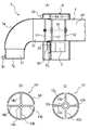
分岐固定ダクト4の先端部4fは、図4(A)に示すように、ほぼ水平に位置決めされており、ハウジング6内でブラケット6a,6bにより支持されている。分岐固定ダクト4の先端部4fは円筒形に形成されており、その内側先端寄りに一対の第1軸受け部材12がその分岐固定ダクト4と同軸に固定されている。第1軸受け部材12は、回転軸18を回転可能な状態で分岐固定ダクト4の先端部4fと同軸に保持する部材であり、図4(C)に示すように構成されている。即ち、第1軸受け部材12は、分岐固定ダクト4の内径とほぼ等しい外径を有する外部リング12rと、軸受けとして働く内部リング12sとを備えており、両リング12r,12sが四本の支持棒12bによって互いに同軸となるように連結されている。
【0010】
分岐固定ダクト4の先端には、曲がりダクト7の基端部7bが軸回りに回動可能な状態で連結される。曲がりダクト7は、側面略L字形をしており、空気吹出口7eを有する先端部7fと曲がり部7w及び上記した基端部7bとから構成されている。曲がりダクト7の基端部7bは円筒形に形成されてその内径が分岐固定ダクト4の先端部4fの外径よりも若干大きく設定されており、図4(A)に示すように、その基端部7bの後端が分岐固定ダクト4の先端に被せられる。
【0011】
曲がりダクト7の基端部7bにはその内部後端寄りに第2軸受け部材14が同軸に固定されている。第2軸受け部材14は、上記した回転軸18に曲がりダクト7を連結するための部材であり、図4(B)に示すように構成されている。即ち、第2軸受け部材14は曲がりダクト7の基端部7bの内径とほぼ等しい外径を有する外部リング14rと、上記した回転軸18が連結される内部リング14sとを備えており、両リング14r,14sが四本の支持棒14bによって互いに同軸となるように連結されている。
上記した構造により、曲がりダクト7は分岐固定ダクト4の軸回りに回動可能になり、空気吹出口7eの向きを変えることが可能になる。
【0012】
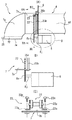
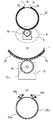
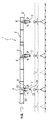
曲がりダクト7の基端部7bの外周面には、図1(A)に示すように、チェーン22がその基端部7bの外周面の周方向に固定されている。チェーン22は、曲がりダクト7を回動させる部材であり、図2(A)に示すように、曲がりダクト7の上端部を除く部分を囲んでいる。なお、図2(A)に示す状態で、曲がりダクト7の空気吹出口7eは真下を向いている。
チェーン22は、少なくとも両端部が連結部材23によって曲がりダクト7に固定されている。連結部材23は、例えば、図1(C)に示すように、チェーン22のピン22pを両側から回転可能に支える一対のL字型サポート23sと、それらのL字型サポート23sを曲がりダクト7に固定するボルト&ナット23nから構成されている。
【0013】
ハウジング6内には、モータ&減速機8が分岐固定ダクト4の真下位置に取付けられており、そのモータ&減速機8の駆動軸8jの先端にチェーン22と噛合するスプロケット8sが固定されている。この構造により、モータ&減速機8が駆動されてスプロケット8sが回転すると、チェーン22及びスプロケット8sの働きで曲がりダクト7は分岐固定ダクト4に対して回動する。
即ち、チェーン22が本発明の係合部材に相当し、スプロケット8s、モータ&減速機8等が本発明の回動部材に相当する。また、L字型サポート23s及びボルト&ナット23nが本発明の連結部材に相当する。
【0014】
曲がりダクト7の基端部7bの外周面には、チェーン22と平行にベルト状の第1ストライカ25aと第2ストライカ25bとが貼着されている。第1ストライカ25aは、図2(C)に示すように、曲がりダクト7の下端から上端近傍までその曲がりダクト7の左外周面に貼着されており、第2ストライカ25bは同じく曲がりダクト7の下端から上端近傍までその曲がりダクト7の右外周面に貼着されている。両ストライカ25a,25bは曲がりダクト7の軸方向に位置をずらした状態で配置されており、互いのストライカ25a,25bが連続しないように配慮されている。
【0015】
ハウジング6の上部には、図2(C)に示すように、第1ストライカ25aによって動作する第1マイクロスイッチ26aと、第2ストライカ25bによって動作する第2マイクロスイッチ26bとが取付けられている。第1マイクロスイッチ26aは、曲がりダクト7の空気吹出口7eが真下を向いた状態からその空気吹出口7eが図中左に移動(曲がりダクト7が右回動)する間だけオンできる位置に取付けられている。第2マイクロスイッチ26bは、曲がりダクト7の空気吹出口7eが真下を向いた状態からその空気吹出口7eが図中右に移動(曲がりダクト7が左回動)する間だけオンできる位置に取付けられている。
【0016】
このため、第1マイクロスイッチ26a、第2マイクロスイッチ26bが共にオンのときは、曲がりダクト7の空気吹出口7eは真下を向いている。また、第1マイクロスイッチ26aがオンで第2マイクロスイッチ26bがオフのときは曲がりダクト7の空気吹出口7eは左下を向いている。第1マイクロスイッチ26aがオフで第2マイクロスイッチ26bがオンのときは曲がりダクト7の空気吹出口7eは右下を向いている。
なお、第1マイクロスイッチ26a、第2マイクロスイッチ26bの信号は、ハウジング6内のコントローラ30(図3参照)に入力される。
【0017】
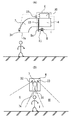
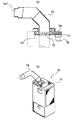
曲がりダクト7の先端部7fには、空気吹出口7eが向く方向に位置する作業員を検出するための主センサ31が取付けられている。また、ハウジング6の上部には、図3(B)に示すように、ハウジング6の左下を指向する第1センサ32と右下を指向する第2センサ33とが取付けられている。第1センサ32は、ハウジング6の真下及びそのハウジング6の左下に位置する作業員を検出可能なように位置決めされている。即ち、第1センサ32によって、図3(B)の範囲I、IIに位置する作業員を検出できる。また、第2センサ33はハウジング6の真下及びそのハウジング6の右下に位置する作業員を検出可能なように位置決めされている。即ち、第2センサ33によって、図3(B)の範囲I 、IIIに位置する作業員を検出できる。
【0018】
主センサ31、第1センサ32及び第2センサ33の出力信号はハウジング6内のコントローラ30(図3参照)に入力される。なお、主センサ31、第1センサ32及び第2センサ33には、例えば赤外線センサが使用される。
コントローラ30は、主センサ31、第1センサ32及び第2センサ33からの信号に基づいてモータ&減速機8を駆動させ、曲がりダクト7の空気吹出口7eを作業員の方向に向ける働きをする。
なお、第1センサ32及び第2センサ33は同じ位置に設けても良く、二つのセンサが一体型となったものを使用しても良い。
【0019】
次に、空調装置1の動作を説明する。
図3(B)に示すように、曲がりダクト7の空気吹出口7eが真下を向いている状態で、作業員がその空気吹出口7eの下(範囲I)にいると、主センサ31、第1センサ32及び第2センサ33が作業員を検出してオンする。主センサ31がオンするとモータ&減速機8は停止し、空気吹出口7eはその位置に保持される。
【0020】
この状態から作業員が図中左方向に移動して範囲IIに到達すると、第1センサ32がオンの状態で主センサ31及び第2センサ33がオフする。これによって、コントローラ30は、曲がりダクト7の空気吹出口7eが左に移動(曲がりダクト7が右回動)するように、モータ&減速機8を駆動させる。即ち、モータ&減速機8によってスプロケット8sが回転させられることにより、そのスプロケット8sの回転力が曲がりダクト7の外周面に固定されたチェーン22に伝わり、両者8s,22の噛合作用で曲がりダクト7が右回動する。そして、曲がりダクト7の主センサ31が作業員を検出してオンすると、モータ&減速機8が停止して、空気吹出口7eはその位置に保持される。
【0021】
次に、作業員が再び範囲Iに戻ると、主センサ31がオフして第1センサ32、第2センサ33が共にオンする。このため、コントローラ30は、曲がりダクト7の空気吹出口7eが真下を向くように、モータ&減速機8を駆動させる。そして、曲がりダクト7の主センサ31が作業員を検出してオンすると、モータ&減速機8が停止して、空気吹出口7eはその位置に保持される。
【0022】
この状態から作業員が図中右方向に移動して範囲IIIに到達すると、第1センサ32、主センサ31がオフして第2センサ33がオンする。これによって、コントローラ30は、曲がりダクト7の空気吹出口7eが右に移動(曲がりダクト7が左回動)するように、モータ&減速機8を駆動させる。そして、曲がりダクト7の主センサ31が作業員を検出してオンすると、モータ&減速機8が停止して、空気吹出口7eはその位置に保持される。
このように、空調装置1では、作業員に追従して自動的に空気吹出口7eを移動させることができる。
【0023】
上記した空調装置1では、曲がりダクト7の回動機構を構成するチェーン22はその曲がりダクト7の外周面の形状に応じて変形可能なため、連結部材23を使用してそのチェーン22を種々の径の曲がりダクトの周方向に固定することができる。即ち、一種類のチェーン22で種々の径の曲がりダクトに対応が可能となる。また、ハウジング6に設けられたモータ&減速機8及びスプロケット8sはチェーン22を介して曲がりダクト7を回動させる構造のため、曲がりダクト7の径に係わらずその曲がりダクト7を回動させることができる。このため、曲がりダクト7を回動させる機構の汎用性が高くなり、曲がりダクト7の径の変更が容易になる。
【0024】
さらに、チェーン22及びスプロケット8s等を使用して曲がりダクト7の回動機構を構成できるため、従来のように、歯車等を使用する場合と比較して回動機構を軽量化できる。
また、チェーン22をL字型サポート22s及びボルト&ナット23nから構成される連結部材23により曲がりダクト7の外周面に固定する構造のため、溶接等で固定する場合と比較して曲がりダクト7を薄肉化できる。
なお、チェーン22の代わりにゴム製のラックを使用し、スプロケット8sの代わりにピニオンを使用することも可能である。
また、曲がりダクト7の上端部を除く部分にチェーン22を固定する例を示したが、曲がりダクト7の全周にチェーン22を固定することも可能である。
さらに、前述の実施形態では、曲がりダクトを水平の軸を中心として回動させる例を説明したが、曲がりダクトを垂直の軸を中心として回動させるようにしても良い。
【0025】
【発明の効果】
本発明によると、曲がりダクトを回動させる機構の汎用性が高くなり、曲がりダクトの径の変更が容易になる。
【図面の簡単な説明】
【図1】本発明の実施形態1に係る空調装置の曲がりダクト及び回動機構を表す側面図(A図)、A図のB部拡大図(B図)、及び連結部材の側面図(C図)である。
【図2】空調装置の曲がりダクト及び回動機構を表す正面図(図1のIIA -IIA矢視図)(A図)、A図のB部拡大図(B図)及び図1のIIC -IIC矢視図(C図)である。
【図3】空調装置の曲がりダクト等におけるセンサ取付け側面図(A図)、正面図(B図)である。
【図4】空調装置の曲がりダクトと固定ダクトとの接続部分を表す縦断面図(A図)、第2軸受け部材の正面図(B図)及び第1軸受け部材の正面図(C図)である。
【図5】空調装置の要部全体正面図である。
【図6】従来の空調装置の曲がりダクト及び回動機構を表す側面図(A図)及び空調装置の全体斜視図(B図)である。
【符号の説明】
1 空調装置
4 分岐固定ダクト(固定ダクト)
7 曲がりダクト
7e 空気吹出口
7b 基端部
8 モータ&減速機(回動部材)
8s スプロケット(回動部材、回転体)
22 チェーン(係合部材)
23 連結部材
23s L字型サポート
23n ボルト&ナット[0001]
BACKGROUND OF THE INVENTION
The present invention relates to an air outlet provided at the distal end of the bent duct by connecting the proximal end portion of the bent duct coaxially to the distal end portion of the fixed duct and rotating the bent duct around the axis of the fixed duct. The present invention relates to an air conditioner that changes the direction.
[0002]
[Prior art]
Japanese Patent Laid-Open No. 5-99479 discloses an example of an air conditioner that rotates a bent duct around the base end axis and changes the direction of the
As shown in FIG. 6A, a
[0003]
[Problems to be solved by the invention]
However, in the structure in which the
The present invention has been made in view of the above problems, and an object of the present invention is to provide an air conditioner including a turning mechanism for a highly versatile bending duct.
[0004]
[Means for Solving the Problems]
The above-described problems are solved by the inventions of the claims.
According to the first aspect of the present invention, the base end portion of the bent duct is coaxially connected to the distal end portion of the fixed duct, the bent duct is rotated around the axis of the fixed duct, and is provided at the distal end of the bent duct. An air conditioner that changes the direction of the air outlet, is deformable along the shape of the outer peripheral surface of the bent duct, and is formed shorter than the outer peripheral dimension of the outer peripheral surface of the bent duct. An engagement member that surrounds the outer peripheral surface from the circumferential direction except for a part of the surface, and an engagement member that surrounds the outer peripheral surface of the bent duct from the circumferential direction at the position of the proximal end of the bent duct. A connecting member that is fixed to the outer peripheral surface of the bent duct in a state in which at least both ends can be removed; a rotating member that is installed on the fixed duct side and rotates the bent duct via the engaging member; the has The rotating member includes a rotating body held at a fixed position, and a plurality of convex portions formed on the outer peripheral surface of the rotating body and a plurality of concave portions provided on the engaging member. When the part is engaged and the rotating body rotates, the engaging position of the convex part of the rotating body and the concave part of the engaging member moves in order, and the bending duct rotates. Features.
[0005]
According to the present invention, since the engaging member can be deformed according to the shape of the outer peripheral surface of the bent duct, the connecting member is used to fix the engaging member in the circumferential direction of the base end portion of the bent duct having various diameters. can do. That is, it is possible to cope with bent ducts having various diameters with a single type of engaging member. Further, since the rotating member on the fixed duct side is configured to rotate the bent duct via the engaging member, the bent duct can be rotated regardless of the diameter of the bent duct. For this reason, the versatility of the mechanism for rotating the bending duct increases, and the diameter of the bending duct can be easily changed.
[0006]
According to the invention of claim 2, the engaging member is a chain, and the rotating body is a sprocket. For this reason, the weight of the air conditioner can be reduced.
It is also possible to form the engaging member with, for example, a rubber rack and to make the rotating body a pinion.
According to the invention of claim 3, the first bearing member for holding the rotating shaft coaxially with the fixed duct is fixed inside the distal end portion of the fixed duct, and the bent portion is bent inside the proximal end portion of the bent duct. A second bearing member that rotatably supports the rotating shaft at a position coaxial with the base end portion of the duct is fixed.
[0007]
DETAILED DESCRIPTION OF THE INVENTION
Hereinafter, the air conditioner according to Embodiment 1 of the present invention will be described with reference to FIGS. Here, FIG. 1 is a side view showing a bending duct and a rotation mechanism of the air conditioner according to the present embodiment, and FIG. 2 is a front view thereof. 3 is a schematic view of sensor mounting of the rotation mechanism, FIG. 4 is a longitudinal sectional view showing a connection portion between the bending duct and the fixed duct, and FIG. 5 is an overall front view of the main part of the air conditioner.
[0008]
As shown in FIG. 5, the air conditioner 1 includes a main fixed duct 2 installed on a ceiling portion of a factory, and a plurality of branch fixed ducts 4 are connected to a side surface of the main fixed duct 2 at a predetermined interval. ing. The distal end portion of the branch fixing duct 4 is accommodated in the
[0009]
As shown in FIG. 4A, the
[0010]
The
[0011]
A second bearing
With the above-described structure, the bending
[0012]
As shown in FIG. 1A, a
At least both ends of the
[0013]
In the
That is, the
[0014]
A belt-like
[0015]
As shown in FIG. 2C, a first
[0016]
For this reason, when both the first
Signals from the first
[0017]
A
[0018]
Output signals from the
The
In addition, the
[0019]
Next, the operation of the air conditioner 1 will be described.
As shown in FIG. 3 (B), when the
[0020]
From this state, when the worker moves to the left in the drawing and reaches the range II, the
[0021]
Next, when the worker returns to the range I again, the
[0022]
From this state, when the worker moves to the right in the drawing and reaches the range III, the
Thus, in the air conditioner 1, the
[0023]
In the air conditioner 1 described above, the
[0024]
Furthermore, since the turning mechanism of the bending
In addition, since the
It is also possible to use a rubber rack instead of the
Moreover, although the example which fixes the
Further, in the above-described embodiment, the example in which the bending duct is rotated about the horizontal axis has been described. However, the bending duct may be rotated about the vertical axis.
[0025]
【The invention's effect】
According to the present invention, the versatility of the mechanism for rotating the bent duct is enhanced, and the diameter of the bent duct can be easily changed.
[Brief description of the drawings]
FIG. 1 is a side view (A view) showing a bending duct and a rotation mechanism of an air conditioner according to Embodiment 1 of the present invention, an enlarged view of a B part in FIG. A (B view), and a side view of a connecting member (C); Figure).
2 is a front view (IIA-IIA arrow view of FIG. 1) (A view), an enlarged view of B part of FIG. A (B view), and IIC − of FIG. It is an IIC arrow line view (C figure).
FIG. 3 is a side view (A view) and a front view (B view) of sensor mounting in a bent duct or the like of an air conditioner.
FIG. 4 is a longitudinal sectional view (A view) showing a connection portion between a bent duct and a fixed duct of an air conditioner, a front view (B view) of a second bearing member, and a front view (C view) of a first bearing member. is there.
FIG. 5 is an overall front view of the main part of the air conditioner.
FIG. 6 is a side view showing a bending duct and a rotation mechanism of a conventional air conditioner (A view) and an overall perspective view of the air conditioner (B view).
[Explanation of symbols]
1 Air conditioner 4 Branch fixed duct (fixed duct)
7
8s sprocket (rotating member, rotating body)
22 Chain (engagement member)
23 connecting member 23s L-shaped
Claims (3)
前記曲がりダクトの外周面の形状に沿って変形可能で、前記曲がりダクトの外周面の外周寸法よりも短く形成されており、その曲がりダクトの外周面の一部を除いて、その外周面を周方向から囲む係合部材と、
前記曲がりダクトの基端部の位置で、その曲がりダクトの外周面を周方向から囲んでいる前記係合部材の少なくとも両端部を取外し可能な状態で前記曲がりダクトの外周面に固定する連結部材と、
前記固定ダクト側に設置されており、前記係合部材を介して前記曲がりダクトを回動させる回動部材とを有しており、
前記回動部材は定位置に保持された回転体を備えており、その回転体の外周面に形成された複数の凸部の一部と前記係合部材に設けられた複数の凹部の一部とが係合するとともに、前記回転体が回転することで、前記回転体の凸部と前記係合部材の凹部との係合位置が順番に移動して曲がりダクトが回動することを特徴とする空調装置。The base end of the bent duct is coaxially connected to the tip of the fixed duct, and the bent duct is rotated around the axis of the fixed duct to change the direction of the air outlet provided at the tip of the bent duct. An air conditioner,
It is deformable along the shape of the outer peripheral surface of the bent duct, and is formed shorter than the outer peripheral size of the outer peripheral surface of the bent duct. An engaging member surrounding from the direction ;
A connecting member for fixing to the outer peripheral surface of the bent duct in a state in which at least both ends of the engaging member surrounding the outer peripheral surface of the bent duct from the circumferential direction can be removed at the position of the base end portion of the bent duct ; ,
It is installed on the fixed duct side, and has a rotating member that rotates the bent duct via the engaging member ,
The rotary member is provided with a rotary member which is held in place, some of the plurality of recesses provided on the engaging member and a portion of the plurality of protrusions formed on the outer peripheral surface of the rotary body When the rotating body rotates, the engaging position of the convex portion of the rotating body and the concave portion of the engaging member moves in order and the bent duct rotates. Air conditioner to do.
係合部材がチェーンであり、回転体がスプロケットであることを特徴とする空調装置。The air conditioner according to claim 1 ,
An air conditioner characterized in that the engaging member is a chain and the rotating body is a sprocket.
固定ダクトの先端部内側には回転軸をその固定ダクトと同軸に保持する第1軸受け部材が固定されており、A first bearing member that holds the rotating shaft coaxially with the fixed duct is fixed inside the front end of the fixed duct,
曲がりダクトの基端部内側にはその曲がりダクトの基端部と同軸位置で前記回転軸を回転可能に支持する第2軸受け部材が固定されていることを特徴とする空調装置。 An air conditioner characterized in that a second bearing member that rotatably supports the rotating shaft at a position coaxial with the base end of the bent duct is fixed inside the base end of the bent duct.
Priority Applications (1)
| Application Number | Priority Date | Filing Date | Title |
|---|---|---|---|
| JP2001171703A JP3772694B2 (en) | 2001-06-06 | 2001-06-06 | Air conditioner |
Applications Claiming Priority (1)
| Application Number | Priority Date | Filing Date | Title |
|---|---|---|---|
| JP2001171703A JP3772694B2 (en) | 2001-06-06 | 2001-06-06 | Air conditioner |
Publications (2)
| Publication Number | Publication Date |
|---|---|
| JP2002364906A JP2002364906A (en) | 2002-12-18 |
| JP3772694B2 true JP3772694B2 (en) | 2006-05-10 |
Family
ID=19013427
Family Applications (1)
| Application Number | Title | Priority Date | Filing Date |
|---|---|---|---|
| JP2001171703A Expired - Fee Related JP3772694B2 (en) | 2001-06-06 | 2001-06-06 | Air conditioner |
Country Status (1)
| Country | Link |
|---|---|
| JP (1) | JP3772694B2 (en) |
-
2001
- 2001-06-06 JP JP2001171703A patent/JP3772694B2/en not_active Expired - Fee Related
Also Published As
| Publication number | Publication date |
|---|---|
| JP2002364906A (en) | 2002-12-18 |
Similar Documents
| Publication | Publication Date | Title |
|---|---|---|
| US4990050A (en) | Wrist mechanism | |
| JP2652354B2 (en) | Industrial robot | |
| JP6640821B2 (en) | Robot structure | |
| JP5270449B2 (en) | Robot joint structure and robot including the same | |
| JPH10329079A (en) | Robot wrist structure | |
| JP7492925B2 (en) | Arm robot | |
| JPH01150042A (en) | Manipulator joint mechanism | |
| JP2572483B2 (en) | Industrial robot equipment | |
| JP4754296B2 (en) | Industrial robot | |
| JPWO2016103301A1 (en) | Articulated robot and its module | |
| JPH028877B2 (en) | ||
| JP3772694B2 (en) | Air conditioner | |
| JP3842125B2 (en) | Air conditioner | |
| JPS5824237B2 (en) | Manipulator arm actuator | |
| JPH106269A (en) | Industrial robot | |
| JP2005014103A (en) | Industrial robot | |
| CN100500388C (en) | Parallel Link Mechanism and Industrial Robot | |
| JP2006007355A5 (en) | ||
| JP2714540B2 (en) | Industrial robot wrist mechanism | |
| JPH09300269A (en) | Wrist mechanism of articulated robot | |
| JP2005014104A (en) | End effectors for industrial robots | |
| JPH072318B2 (en) | Articulated robot | |
| JPS5837117B2 (en) | Joints in manipulators, etc. | |
| JP2003275977A (en) | SCARA robot | |
| JP2002266954A (en) | Motor actuator |
Legal Events
| Date | Code | Title | Description |
|---|---|---|---|
| A977 | Report on retrieval |
Free format text: JAPANESE INTERMEDIATE CODE: A971007 Effective date: 20050927 |
|
| A131 | Notification of reasons for refusal |
Free format text: JAPANESE INTERMEDIATE CODE: A131 Effective date: 20051004 |
|
| A521 | Written amendment |
Free format text: JAPANESE INTERMEDIATE CODE: A523 Effective date: 20051130 |
|
| A711 | Notification of change in applicant |
Free format text: JAPANESE INTERMEDIATE CODE: A711 Effective date: 20051130 |
|
| TRDD | Decision of grant or rejection written | ||
| A521 | Written amendment |
Free format text: JAPANESE INTERMEDIATE CODE: A821 Effective date: 20051130 |
|
| A01 | Written decision to grant a patent or to grant a registration (utility model) |
Free format text: JAPANESE INTERMEDIATE CODE: A01 Effective date: 20060124 |
|
| A61 | First payment of annual fees (during grant procedure) |
Free format text: JAPANESE INTERMEDIATE CODE: A61 Effective date: 20060206 |
|
| R150 | Certificate of patent or registration of utility model |
Free format text: JAPANESE INTERMEDIATE CODE: R150 |
|
| LAPS | Cancellation because of no payment of annual fees |