JP3772681B2 - Optical information recording method and apparatus - Google Patents
Optical information recording method and apparatus Download PDFInfo
- Publication number
- JP3772681B2 JP3772681B2 JP2001047439A JP2001047439A JP3772681B2 JP 3772681 B2 JP3772681 B2 JP 3772681B2 JP 2001047439 A JP2001047439 A JP 2001047439A JP 2001047439 A JP2001047439 A JP 2001047439A JP 3772681 B2 JP3772681 B2 JP 3772681B2
- Authority
- JP
- Japan
- Prior art keywords
- recording
- light
- power
- laser
- optimum
- Prior art date
- Legal status (The legal status is an assumption and is not a legal conclusion. Google has not performed a legal analysis and makes no representation as to the accuracy of the status listed.)
- Expired - Fee Related
Links
Images
Landscapes
- Optical Head (AREA)
- Optical Recording Or Reproduction (AREA)
Description
【0001】
【発明の属する技術分野】
本発明は、追記または書き換え可能な光ディスクに光学的に情報を記録する技術に関し、特に、光ディスクへの記録を行う際に、記録中にその光ディスクからの反射光を受光して適切な光量となるように光量制御を行うランニングOPC(Optimum Power Control)手法および事前に最適記録パワーを求めるOPC手法を用いた光学的情報記録方法および装置に関する。
【0002】
【従来の技術】
追記または書き換え可能な光ディスクは、そのメディア面(記録面、記録層)にレーザ光を局所定に照射して、高反射率であるクリスタル状態の部分と低反射率であるアモルファス状態の部分との組み合わせからなる記録マークおよびスペースを形成することにより情報の記録がなされる。
しかし、記録するレーザ光のパワーにより記録マークの形状状態が変化するため、従来においては、記録媒体の特性に適した記録パワーを求めるために、記録開始の準備として予め所定の領域に記録パワーを変化させながら試し書きを行い、試し書き後、その領域中で再生信号の対称性(Asymmetry)が最も良好であるエリアを記録したパワーを最適記録パワーとして求める、といういわゆるOPC法が用いられている。実際のデータの記録時にはこのようにして求めた最適記録パワーを維持しながら記録を行う。
ところが、たとえ試し書きによって最適記録パワーを得て、その最適記録パワーを保ちながらデータを記録するようにしていても、半導体レーザの発光出力の温度変化などにより記録媒体に照射されるパワーが最適記録パワーと異なったり、記録媒体の面内の感度ぱらつき、或いは、チルトと呼ばれるレーザ照射光に対するディスクの傾き等により、最適となる記録パワーがデータ記録領域内で異なったりと、常に最適記録パワーで記録することかできない、という問題がある。このような問題に対し、一般には実際のデータ領域への記録を行う前にディスクの最内周にあるパワーキャリブレーション領域(PCA)へパワーを段階的に変えながら試し書きをおこなうOPCによって最適なレーザパワーを決定することで対処している。
さらには、実際の記録中においても、記録している領域でのメディアの面内感度ばらつきや回転している光ディスクの傾き(チルト)などによりレーザ光によるメディア変化の度合いが悪くなる場合がある。これに対処するために、記録中の反射光を受光してその光量変動の状態から記録具合いを判断し、発光量を増減することによりリアルタイムにレーザパワー制御を行い、メディア面で最適な記録状態とする制御手法であるランニングOPCが、とくに色素系の追記型光ディスクに対して実用化されている。(特開2000−020957公報参照)
【0003】
【発明が解決しようとする課題】
しかしながら、ランニングOPCによって光ディスクのメディア面で記録状態を検知することはパワー変動の記録による影響がみられることが前提であり、その感度はメディアの特性によりまちまちであり光ディスクドライブ装置で一意に決めることができない。
また、CD-RとDVD-Rのように色素材料や記録密度の違いによって、単一な矩形状パルスを用いたり、クロック周期で加熱と冷却を繰り返すマルチパルスを用いてマーク部を形成する記録方式の違いによっても、記録する光量の変化に対する反射光の変化の大小は異なっている。さらに、パワー変化に対して記録されるメディア変化の度合いが小さい場合、検出誤差や一時的な傷などのときのみパワーが変更されることになり、このような場合の過敏な応答により逆にランニングOPCによる悪影響があるなどの不具合がある。
本発明は、このような従来技術の不具合を解消するべく創案されたものであり、記録媒体の特性に依存せず、ランニングOPCでの記録パワー変更による効果を常に有効なものとして記録を行うことができる光学的情報記録方法及び装置を提供することを課題とする。
【0004】
【課題を解決するための手段】
上記課題を解決するために、請求項1記載の発明は、レーザ光を記録媒体に照射してそのレーザ光の強弱により反射率の異なる領域を形成することでマークとスペースの情報を記録する記録工程と、記録中における前記記録媒体からの反射光を受光する受光工程と、前記記録媒体に照射されるレーザ光の光量を変更するように前記記録工程のレーザパワーを設定する出力光量変更工程と、記録状態が一定となるように前記記録工程のレーザパワーを調整する記録時最適パワー調整工程と、記録された領域の反射光量を測定して出力する最適なレーザ光量を決定する最適レーザパワー算出工程とを備えた光学的情報記録方法であって、事前に前記記録工程による記録中に前記出力光量変更工程によりレーザ光の光量を段階的に変化させて記録しつつ、前記受光工程によって反射光を取得するとともに、前記最適レーザパワー算出工程によりレーザ光量の決定を行い、そのレーザ光量が光量変動に応じて取得した反射光の変動が大きい個所の光量である場合に前記記録時最適パワー調整工程による制御を実施するようにしたことを特徴とする。
【0005】
また、請求項2記載の発明は、請求項1記載の光学的情報記録方法において、前記記録時最適パワー調整工程は、前記記録工程のレーザパワーを前記受光工程により反射光の変動が検出される範囲内に制限して調整することを特徴とする。
また、請求項3記載の発明は、請求項2記載の光学的情報記録方法において、前記記録媒体の一部領域において前記記録工程による記録中に前記出力光量変更工程によりレーザ光の光量を段階的に変化させて記録しつつ、前記受光工程によって反射光を取得する制御を前記最適レーザパワー算出工程内で行うようにしたことを特徴とする。
【0006】
また、請求項4記載の発明は、レーザ光を記録媒体に照射してそのレーザ光の強弱により反射率の異なる領域を形成することでマークとスペースの情報を記録する記録手段と、記録中における前記記録媒体からの反射光を受光する受光手段と、前記記録媒体に照射されるレーザ光の光量を変更するように前記記録手段のレーザパワーを設定する出力光量変更手段と、記録状態が一定となるように前記記録手段のレーザパワーを調整する記録時最適パワー調整手段と、記録された領域の反射光量を測定して出力する最適なレーザ光量を決定する最適レーザパワー算出手段と、を備えた光学的情報記録装置において、事前に前記記録手段による記録中に前記出力光量変更手段によりレーザ光の光量を段階的に変化させて記録しつつ、前記受光手段によって反射光を取得するとともに、前記最適レーザパワー算出手段によりレーザ光量の決定を行い、そのレーザ光量が光量変動に応じて取得した反射光の変動が大きい個所の光量である場合に前記記録時最適パワー調整手段による制御を実施するように構成したことを特徴とする。
また、請求項5記載の発明は、請求項4記載の光学的情報記録装置において、前記記録時最適パワー調整手段は、前記記録手段のレーザパワーを前記受光手段により反射光の変動が検出される範囲内に制限して調整することを特徴とする。
また、請求項6記載の発明は、請求項5記載の光学的情報記録装置において、前記記録媒体の一部領域において前記記録手段による記録中に前記出力光量変更手段によりレーザ光の光量を段階的に変化させて記録しつつ、前記受光手段によって反射光を取得する制御を前記最適レーザパワー算出手段内で行うように構成したことを特徴とする。
【0007】
【発明の実施の形態】
以下、本発明の実施の形態について説明する。
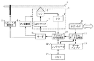
図1は本発明の光学的情報記録装置の実施の形態の一例を示すブロック図である。図1において1は照射されるレーザ光の強弱により情報が記録される光ディスク(記録媒体)である。光ディスク1はスピンドル駆動部6によって回転されトラックと呼ばれる内周から外周へ向けての記録溝をもつ。ピックアップ部2はレーザ光を光ディスク1に向けて出射し、また同時に反射光を受光してトラックに追従しながら記録または再生を行う。ピックアップ部2はさらにレーザ発光するLD(Laser Diode)部3とそれを発光駆動させるLDドライバ部7や、LD部3からのレーザ光が光ディスク1で反射して戻ってきた反射光を受光するPD(Photo Detector)部4などからなる。PD部4はその光信号を電気的なRF信号としてアナログ信号処理部10へ渡して処理し、アナログ信号処理部10はそれをさらにサーボ部9へ送り、その信号情報からPU駆動部6に対してピックアップ部2のトラック制御、フォーカス制御、シーク制御などをおこなう。 またスピンドル駆動部5に対する回転制御を行う。さらにアナログ信号処理部10は再生時およびマーク記録時にRF信号をサンプリングする機能を持つ。記録されるデータは、図示しない外部のホストコンピュータからホストI/F部8を通じてデジタルデータ処理部11によってデータバッファ部13へ格納され、記録用のデータ形式(パルス発光パターン)へデータ変換され、アナログ信号処理部10を介してLDドライバ部7へ送られてLD部3でレーザ光により記録される。コントローラ部12はデジタルデータ処理部11やアナログ信号処理部10に対して記録の前後においてデータや信号の処理の切り替えなどを指示する制御命令を出す。また、コントローラ部12はデジタルデータ処理部11やアナログ信号処理部10を始めとした各ブロック部を直接的、間接的に制御することによって一連の制御動作を実現し、総じてはこの光学的情報記録装置全体を統括制御している。 コントローラ部12はその制御手順をプログラムとして格納するROMや作業領域としてのRAMなどからなるメモリ部14との間でデータを送受信することで動作する。
次に、図1のように構成された光学的情報記録装置の動作について説明する。以下の制御はコントローラ部12によってなされる。
【0008】
[第1の動作例]
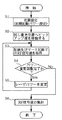
図2に実際のデータの記録前に記録中のRF信号感度を調べる事前RFサンプリング制御手順を示す。
まず、初期設定として、記録パワーを変更する回数及びその各パワー設定値を決めておき、その一つを初期記録パワー値としてLDドライバ7へ設定しておく(S1)。次に光ディスク1のユーザ記録領域でない位置、例えば試し書き位置(通常はPCA領域)へレーザ光が照射されるようピックアップ部2を移動する(S2)。記録を開始し、同時にRF信号の値(反射光量)をPD部4からアナログ信号処理部10を通じて取得する(S3)。S1で規定しておいた記録パワーを変更する回数をすでに終わっていればS6へ進む(S4)。そうでなければS1で定めておいた別のパワーに変更(S5)してS3にもどり、記録中のRF信号値の取得を繰り返す。S6ではS2またはS5で設定したレーザパワーとS3で取得したRF信号値の集計をおこなう。ここではサンプル値の変動が大きいレーザパワーの範囲を把握し、またその範囲内のパワーを選択して 実際の記録時のパワーとしてLDドライバ7に設定する。
S6の前までで試し書き領域においてレーザパワーを変動させ、それぞれの 時のRF信号を取得している。その結果から、RF信号の変動が大きいレーザパワー範囲を求め、その範囲内のあるパワーを実際に記録する領域の初期パワーとして設定する。
以上で事前RFサンプリング制御手順は終了する。このように事前に段階的にパワーを変えて記録し、その際の反射光を取得してた結果から反射光量の感度の高い個所のパワーを実際に記録するパワーとして設定することで、光ディスクのメディア面の特性などによらず、ランニングOPCでの記録パワー変更による効果を常に有効なものとして記録を行うことができる。
【0009】
[第2の動作例]
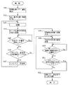
第2の動作例では、図2に示した事前RFサンプリングとともにOPCを実行し、OPC結果による最適記録パワーがランニングOPCで有用であるか否か判断する。
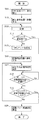
まず、図3を用いてOPC実行時の制御手順を説明する。OPC実行手順では、段階的に変えるOPC記録パワーの初期値をLDドライバ部7に設定する(S11)。次に試し書き領域へピックアップ部2を移動し(S12)、記録を開始する(S13)。所定量のデータの記録がおえたら、これまで所定の回数分のパワー変更が終わったか否か判断する(S14)。終わっていればS16へ進む。そうでなければ次のOPCパワー設定値をLDドライバ部7に設定してS13に戻り、記録制御を繰り返す(S15)。S16では最初の記録位置にレーザ光が照射されるようにピックアップ部2を戻し(S16)、再生パワーで光ディスク1からの反射光をPD部4からアナログ信号処理部10を通じてRF信号の値を取得する(S17)。次に同一パワーで記録した領域の境界を越えたか否か判断し、そうでなければ越えるまで待ちつづける(S18)。ここで領域の境界を越えていないときにS17まで戻り、複数のRF信号の値を取得してもよい。同一記録パワー記録領域の境界を越えたら、S14で記録したときと同じOPCパワーの変更と同じ回数のRF信号値取得が完了したか否か判断し(S19)、完了していればS20へ進む。そうでなければS17へ戻る。S20ではS17で取得したRF信号値から最適な記録パワーを算出し(S20)、OPCを終了する。
このときの最適パワーの算出法は一般にはモジュレーション法であったり、またβ法であったりするがここではその手法は問わない。モジュレーション法は、RF信号の最大振幅(Ip−p)と最大値(Imax)との比(M=Ip−p/Imax)がある目標値(例えば0.65)となる時の記録パワーを最適パワーとして決定する手法である。β法は、アシンメトリβがAC結合後のRF信号の正側のピークレベルX1、負側のピークレベルX2を用いてβ=(X1+X2)/(X1−X2)として算出され、それがそのメディアで規定された値となる時の記録パワーを最適パワーとして決定する手法である。
【0010】
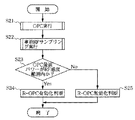
図4にOPC結果による最適記録パワーがランニングOPCで有用であるか否か判断する制御手順を示す。図3の手順でOPCを実行して最適記録パワーを求め(S21)、さらに図2で説明した事前RFサンプリング制御を行って記録パワー変動による記録時での反射光変化の感度を取得する(S22)。次にS21のOPCによって求めた最適パワーがS22によって把握したRF信号の感度内であるかどうかを調べる(S23)。感度範囲になければランニングOPCが無効と判断して、以降の実際の記録時にはランニングOPC制御を行わないようにする(S25)。また、感度範囲内であればランニングOPCが有効と判断して、以降の実際の記録時にはランニングOPC制御を実施することを決定する。
S21のOPCで決定した最適パワーの周辺でパワーを変動させるランニングOPCをおこなったとして、効果があるかどうかを前もって考慮し、実際の記録においてランニングOPCを実施するどうかを決定する。
S23ではOPC最適パワーがS22で求めたRF信号の変動が大きいレーザパワーの範囲に入っているかどうかでその判断をしている。S24、S25によって本制御は終了する。
このように、事前に段階的にパワーを変えて記録し、その記録時での反射光量の感度が良いかどうかを記録前に把握しておくことで、OPCによるそのメディアに対する記録状態の良い記録パワーにおいてランニングOPCが有効かどうか否か判断することができる。
図4のS23でOPCによる最適記録パワーがRF感度範囲内であるとして、S24でランニングOPCを有効とした場合、さらにランニングOPCの記録パワー変動をそのRF感度範囲内のパワーとすることが望ましい。
このように事前に段階的にパワーを変えて記録し、その際の反射光を取得した結果から記録時での反射光量の感度が良いかどうかを記録前に把握しておき、さらにその感度の良い範囲でランニングOPCによる記録パワーの変更を制限することで、ランニングOPCが有効に動作することを保証することができる。
【0011】
[第3の動作例]
第2の動作例では、OPCを実行した後、OPC結果による最適記録パワーがランニングOPCで有用であるか否か判断しているが、OPCを実行すると同時に記録中のRF信号感度を調べるようにしてもよい。この場合の制御手順を図5に示す。
図5ではまず、段階的に変えるOPC記録パワーの初期値をLDドライバ部7に設定する(S41)。次に試し書き領域へピックアップ部2を移動し(S42)、記録を開始する(S43)。記録開始後すぐにマーク記録の反射光によるRF信号のサンプリングを行い、値を取得する(S44)。所定データ量を記録し終えているかを確認し(S45)、終えたらOPCパワー変更の回数分が終わったか否か判断する(S46)。終わっていればS48へ進む。そうでなければ次のOPCパワー設定値をLDドライバ部7に設定し(S47)、S43に戻り記録制御を繰り返す。S48では再び最初の記録位置にレーザ光が照射されるようにピックアップ部2を戻し(S48)、再生パワーで光ディスク1からの反射光をPD部4からアナログ信号処理部10を通じてRF信号の値を取得する(S49)。次に同一のパワーで記録した領域の境界を越えたか否か判断し(S50)、そうでなければ越えるまで待つ。ここで了解の境界を越えていないときにS49までもどり、複数のRF信号の値を取得してもよい。境界を越えていればOPCのパワー変更の回数のRF信号値を取得したか否か判断し、取得が完了していればS52に進み、そうでなければS49へ戻り、RF信号の値の取得を繰り返す。S52ではS51で取得したRF信号値から最適な記録パワーを算出し、そのパワーがRF信号の感度が良好な範囲かどうかでランニングOPCを実行するかどうかを決定する。
【0012】
S51の結果から最適な記録パワーを算出するのは従来のOPC手法によるものである。そのOPCによる最適パワーがS44で取得した結果から記録中のRF信号の変動の大きい範囲に入っていればランニングOPCを実施する。そうでなければ実施しないという決定をするのである。
このように、OPCと同時に記録中のRF信号感度を調べるRFサンプリング制御を実施することで、記録パワー変更を一度で行うことができ、また利用する試し書き領域を少なくすることができる。
上述したように、本発明によれば、メディア面で記録状態を検知できる記録パワー変化の範囲を判断することでメディアの特性である色素材料の感度の違いや、単一な矩形状パルスやマルチパルスなどの記録方式の違いによってもランニングOPCを効果的に実施できる。さらには検出誤差や一時的な傷などのための過敏応答による悪影響を抑えることができる。
【0013】
【発明の効果】
以上説明してきたように、請求項1記載の光学的情報記録方法によれば、事前に段階的にパワーを変えて記録し、その記録時での反射光量の感度が良いかどうかを記録前に把握しておくことで、OPCによるそのメディアに対する記録状態の良い記録パワーにおいてランニングOPCが有効かどうか否かを判断することができる。
また、請求項2記載の光学的情報記録方法によれば、事前に段階的にパワーを変えて記録し、その際の反射光を取得した結果から記録時での反射光量の感度が良いかどうかを記録前に把握しておき、さらにその感度の良い範囲でランニングOPCによる記録パワーの変更を制限することで、ランニングOPCが有効に動作することを保証することができる。
また、請求項3記載の光学的情報記録方法によれば、事前に段階的にパワーを変えて記録し、その際の反射光を取得した結果から記録時での反射光量の感度が良いかどうかをOPCの記録中に行うことで実際のユーザデータの記録を行うまでの時間短縮や利用する試し書きの領域を小さくすることができる。
【0014】
また、請求項4記載の光学的情報記録装置によれば、事前に段階的にパワーを変えて記録し、その記録時での反射光量の感度が良いかどうかを記録前に把握しておくことで、OPCによるそのメディアに対する記録状態の良い記録パワーにおいてランニングOPCが有効かどうか否かを判断することができる。
また、請求項5記載の光学的情報記録装置によれば、事前に段階的にパワーを変えて記録し、その際の反射光を取得した結果から記録時での反射光量の感度が良いかどうかを記録前に把握しておき、さらにその感度の良い範囲でランニングOPCによる記録パワーの変更を制限することで、ランニングOPCが有効に動作することを保証することができる。
また、請求項6記載の光学的情報記録装置によれば、事前に段階的にパワーを変えて記録し、その際の反射光を取得した結果から記録時での反射光量の感度が良いかどうかをOPCの記録中に行うことで実際のユーザデータの記録を行うまでの時間短縮や利用する試し書きの領域を小さくすることができる。
【図面の簡単な説明】
【図1】本発明の光学的情報記録装置の実施の形態の一例を示すブロック図である。
【図2】実際のデータの記録前に記録中のRF信号感度を調べる事前RFサンプリング制御手順を示すフローチャートである。
【図3】OPC実行時の制御手順を示すフローチャートである。
【図4】OPC結果による最適記録パワーがランニングOPCで有用であるか否か判断する際の制御手順を示すフローチャートである。
【図5】OPC実行と同時に記録中のRF信号感度を調べる場合の制御手順を示すフローチャートである。
【符号の説明】
1:光ディスク(記録媒体)
2:ピックアップ部
3:LD部
4:PD部
5:スピンドル駆動部
6:PU駆動部
7:LDドライバ部
8:ホストI/F部
9:サーボ部
10:アナログ信号処理部
11:デジタルデータ処理部[0001]
BACKGROUND OF THE INVENTION
The present invention relates to a technique for optically recording information on a write-once or rewritable optical disc, and in particular, when recording on an optical disc, the reflected light from the optical disc is received during recording to obtain an appropriate amount of light. The present invention relates to a running OPC (Optimum Power Control) method for performing light quantity control and an optical information recording method and apparatus using an OPC method for obtaining an optimum recording power in advance.
[0002]
[Prior art]
A write-once or rewritable optical disc is irradiated with laser light on the media surface (recording surface, recording layer) in a predetermined manner so that a crystal portion having a high reflectivity and an amorphous portion having a low reflectivity are formed. Information is recorded by forming a combination of recording marks and spaces.
However, since the shape of the recording mark changes depending on the power of the laser beam to be recorded, conventionally, in order to obtain a recording power suitable for the characteristics of the recording medium, the recording power is applied to a predetermined area in advance as a preparation for starting recording. A so-called OPC method is used in which trial writing is performed while changing, and after the trial writing, the power for recording the area where the reproduction signal has the best symmetry is obtained as the optimum recording power. . During actual data recording, recording is performed while maintaining the optimum recording power thus obtained.
However, even if the optimum recording power is obtained by trial writing and data is recorded while maintaining the optimum recording power, the power applied to the recording medium due to the temperature change of the light emission output of the semiconductor laser is optimum recording. Always record with the optimum recording power, which differs from the power, the sensitivity fluctuation in the surface of the recording medium, or the optimum recording power in the data recording area due to the tilt of the disc with respect to the laser irradiation light called tilt. There is a problem that you can't do it. In order to solve such a problem, in general, it is most suitable by OPC that performs test writing while changing the power step by step to the power calibration area (PCA) in the innermost circumference of the disk before recording in the actual data area. This is dealt with by determining the laser power.
Further, even during actual recording, the degree of media change due to laser light may deteriorate due to variations in the in-plane sensitivity of the media in the recording area, tilt of the rotating optical disk, and the like. In order to cope with this, the reflected light during recording is received, the recording condition is judged from the state of fluctuation of the light quantity, and the laser power control is performed in real time by increasing or decreasing the light emission amount, and the optimum recording state on the media surface The running OPC, which is a control method, has been put into practical use particularly for dye-based write-once optical discs. (See JP 2000-020957 A)
[0003]
[Problems to be solved by the invention]
However, detection of the recording state on the media surface of the optical disk by running OPC is based on the premise that there is an effect of recording power fluctuations, and the sensitivity varies depending on the characteristics of the media and must be uniquely determined by the optical disk drive device. I can't.
Also, a recording that uses a single rectangular pulse or a multi-pulse that repeats heating and cooling at a clock cycle to form a mark portion, such as CD-R and DVD-R, depending on the dye material and recording density. Depending on the method, the magnitude of the change in reflected light with respect to the change in the amount of light to be recorded differs. Furthermore, when the degree of media change recorded with respect to the power change is small, the power is changed only when there is a detection error or a temporary scratch. There are inconveniences such as an adverse effect of OPC.
The present invention was devised to solve such problems of the prior art, and recording is performed with the effect of changing the recording power in running OPC being always effective without depending on the characteristics of the recording medium. It is an object of the present invention to provide an optical information recording method and apparatus capable of achieving the above.
[0004]
[Means for Solving the Problems]
In order to solve the above problems, the invention according to claim 1 is a recording in which information on marks and spaces is recorded by irradiating a recording medium with laser light and forming regions having different reflectivities depending on the intensity of the laser light. a step, a light receiving step of receiving reflected light from the recording medium during recording, the output light amount changing step of setting the laser power of the recording step so as to change an amount of the laser light irradiated on the recording medium , Optimum power adjustment process during recording to adjust the laser power of the recording process so that the recording state is constant, and optimum laser power calculation to determine the optimum laser light quantity to be output by measuring the reflected light quantity of the recorded area a process and an optical information recording method provided with the light amount of the laser beam stepwisely were recorded and changed by the output light amount changing step during the recording by the recording step in advance One obtains the reflected light by the light receiving step, the optimum makes decisions laser light amount by the laser power calculating step, when the amount of laser light is the light quantity of the point a large variation of the acquired reflected light in accordance with the light amount variation Further, the control by the optimum power adjustment process at the time of recording is performed.
[0005]
Further, an invention according to claim 2, wherein, in the optical information recording method according to claim 1, wherein the recording time of the optimum power adjustment process, the variation of the reflected light is detected laser power of the recording process by the light receiving step It is characterized by adjusting within the range.
The invention of
[0006]
According to a fourth aspect of the present invention, there is provided a recording means for recording mark and space information by irradiating a recording medium with a laser beam and forming regions having different reflectivities depending on the intensity of the laser beam, A light receiving means for receiving reflected light from the recording medium, an output light quantity changing means for setting a laser power of the recording means so as to change a light quantity of the laser light applied to the recording medium, and a recording state is constant. And an optimum power adjustment means for recording that adjusts the laser power of the recording means, and an optimum laser power calculation means for determining the optimum laser light quantity to be output by measuring the reflected light quantity of the recorded area. In the optical information recording apparatus, the light receiving unit is configured to record the light amount of the laser beam in a stepwise manner by the output light amount changing unit during recording by the recording unit in advance. Therefore, the reflected light is acquired, and the laser light quantity is determined by the optimum laser power calculating means. When the laser light quantity is a light quantity at a location where the fluctuation of the reflected light obtained according to the light quantity fluctuation is large, the optimum at the time of recording. It is characterized in that the control by the power adjusting means is performed.
According to a fifth aspect of the present invention, in the optical information recording apparatus according to the fourth aspect of the invention, the optimum power adjusting means for recording detects the laser power of the recording means and the fluctuation of reflected light by the light receiving means. It is characterized by adjusting within the range.
According to a sixth aspect of the present invention, in the optical information recording apparatus according to the fifth aspect, the amount of laser light is stepped by the output light amount changing means during recording by the recording means in a partial area of the recording medium. The control for acquiring the reflected light by the light receiving means is performed in the optimum laser power calculating means while recording the image in a changed manner.
[0007]
DETAILED DESCRIPTION OF THE INVENTION
Embodiments of the present invention will be described below.
FIG. 1 is a block diagram showing an example of an embodiment of an optical information recording apparatus of the present invention. In FIG. 1, reference numeral 1 denotes an optical disk (recording medium) on which information is recorded by the intensity of irradiated laser light. The optical disk 1 is rotated by a
Next, the operation of the optical information recording apparatus configured as shown in FIG. 1 will be described. The following control is performed by the
[0008]
[First operation example]
FIG. 2 shows a pre-RF sampling control procedure for checking the RF signal sensitivity during recording before recording actual data.
First, as the initial setting, the number of times of changing the recording power and each power setting value are determined, and one of them is set as the initial recording power value in the LD driver 7 (S1). Next, the pickup unit 2 is moved so that the laser beam is irradiated to a position other than the user recording area of the optical disc 1, for example, a test writing position (usually a PCA area) (S2). Recording is started, and at the same time, the value of the RF signal (the amount of reflected light) is acquired from the
Before S6, the laser power is varied in the trial writing area, and the RF signal at each time is acquired. From the result, a laser power range in which the fluctuation of the RF signal is large is obtained, and a certain power within the range is set as an initial power of an area where recording is actually performed.
Thus, the preliminary RF sampling control procedure ends. In this way, by changing the power step by step in advance and recording the reflected light at that time, by setting the power of the portion where the reflected light quantity is highly sensitive as the actual recording power, Regardless of the characteristics of the media, recording can be performed with the effect of changing the recording power in running OPC being always effective.
[0009]
[Second operation example]
In the second operation example, OPC is executed together with the pre-RF sampling shown in FIG. 2, and it is determined whether or not the optimum recording power based on the OPC result is useful in running OPC.
First, a control procedure when executing OPC will be described with reference to FIG. In the OPC execution procedure, an initial value of the OPC recording power that is changed step by step is set in the LD driver unit 7 (S11). Next, the pickup unit 2 is moved to the trial writing area (S12), and recording is started (S13). When the recording of the predetermined amount of data is completed, it is determined whether or not the power change for the predetermined number of times has been completed (S14). If completed, go to S16. Otherwise, the next OPC power setting value is set in the LD driver unit 7 and the process returns to S13 to repeat the recording control (S15). In S16, the pickup unit 2 is returned so that the first recording position is irradiated with the laser beam (S16), and the reflected light from the optical disk 1 is obtained from the
The calculation method of the optimum power at this time is generally a modulation method or a β method, but the method is not limited here. The modulation method is used when the ratio (M = I p−p / I max ) between the maximum amplitude (I p−p ) and the maximum value (I max ) of the RF signal reaches a certain target value (for example, 0.65). This is a method for determining the recording power as the optimum power. In the β method, asymmetry β is calculated as β = (X 1 + X 2 ) / (X 1 −X 2 ) using the positive peak level X 1 and the negative peak level X 2 of the RF signal after AC coupling. This is a method for determining the recording power when it becomes a value specified by the medium as the optimum power.
[0010]
FIG. 4 shows a control procedure for determining whether or not the optimum recording power based on the OPC result is useful in the running OPC. The OPC is executed according to the procedure of FIG. 3 to obtain the optimum recording power (S21), and the prior RF sampling control described with reference to FIG. 2 is performed to obtain the sensitivity of the reflected light change during recording due to the recording power fluctuation (S22). ). Next, it is examined whether or not the optimum power obtained by the OPC in S21 is within the sensitivity of the RF signal obtained in S22 (S23). If it is not within the sensitivity range, it is determined that the running OPC is invalid, and the running OPC control is not performed during the subsequent actual recording (S25). If it is within the sensitivity range, it is determined that the running OPC is effective, and it is determined that the running OPC control is to be performed in the subsequent actual recording.
Whether or not the running OPC is performed in the actual recording is determined by considering in advance whether or not there is an effect, assuming that the running OPC that varies the power around the optimum power determined by the OPC in S21 is performed.
In S23, the determination is made based on whether or not the OPC optimum power is within the laser power range in which the fluctuation of the RF signal obtained in S22 is large. This control is terminated by S24 and S25.
As described above, recording is performed with the power changed stepwise in advance, and by recording whether or not the sensitivity of the reflected light quantity at the time of recording is good before recording, recording with good recording state on the medium by OPC is possible. It can be determined whether or not running OPC is effective in power.
Assuming that the optimum recording power by OPC is within the RF sensitivity range in S23 of FIG. 4, when running OPC is validated in S24, it is desirable to further change the recording power fluctuation of the running OPC within the RF sensitivity range.
In this way, recording with varying power step by step in advance, from the result of obtaining the reflected light at that time, know whether the sensitivity of the reflected light amount at the time of recording is good before recording, and further of the sensitivity By restricting the change in recording power by running OPC within a good range, it is possible to ensure that running OPC operates effectively.
[0011]
[Third operation example]
In the second operation example, after the OPC is executed, it is determined whether or not the optimum recording power based on the OPC result is useful in the running OPC. However, the RF signal sensitivity during recording is checked simultaneously with the OPC. May be. The control procedure in this case is shown in FIG.
In FIG. 5, first, the initial value of the OPC recording power that is changed step by step is set in the LD driver unit 7 (S41). Next, the pickup unit 2 is moved to the trial writing area (S42), and recording is started (S43). Immediately after the start of recording, the RF signal is sampled by the reflected light of the mark recording to obtain a value (S44). It is confirmed whether or not the recording of the predetermined data amount has been completed (S45). When the recording is completed, it is determined whether or not the number of times of OPC power change has been completed (S46). If completed, go to S48. Otherwise, the next OPC power set value is set in the LD driver unit 7 (S47), and the process returns to S43 to repeat the recording control. In S48, the pickup unit 2 is returned so that the first recording position is again irradiated with the laser beam (S48), and the reflected light from the optical disk 1 is reproduced from the
[0012]
The optimum recording power is calculated from the result of S51 by the conventional OPC method. If the optimum power by the OPC is within a range where the fluctuation of the RF signal being recorded is large from the result obtained in S44, the running OPC is performed. Otherwise, it decides not to do it.
As described above, by performing the RF sampling control for checking the RF signal sensitivity during recording simultaneously with the OPC, the recording power can be changed at one time, and the test writing area to be used can be reduced.
As described above, according to the present invention, it is possible to determine the range of the recording power change in which the recording state can be detected on the media surface, thereby determining the difference in the sensitivity of the dye material, which is the characteristic of the media, The running OPC can be effectively carried out by the difference in the recording method such as the pulse. Furthermore, adverse effects due to hypersensitive responses due to detection errors and temporary flaws can be suppressed.
[0013]
【The invention's effect】
As has been described, according to the optical information recording method according to claim 1, advance stepwise recorded by changing the power, whether the sensitivity of the reflected light amount at the time of recording is good before recording By knowing, it is possible to determine whether or not the running OPC is effective at a recording power with a good recording state for the medium by OPC.
According to the optical information recording method of the second aspect, whether the sensitivity of the reflected light quantity at the time of recording is good from the result of acquiring the reflected light at that time and changing the power stepwise in advance. Can be ascertained before recording, and by restricting the change in recording power by running OPC within the range of good sensitivity, it can be assured that running OPC operates effectively.
Further, according to the optical information recording method of
[0014]
Further, according to the optical information recording apparatus of the fourth aspect, recording is performed by changing the power stepwise in advance, and it is grasped before recording whether or not the sensitivity of the reflected light quantity at the time of recording is good. Thus, it can be determined whether or not the running OPC is effective at a recording power with a good recording state for the medium by OPC.
Further, according to the optical information recording apparatus of the fifth aspect, whether or not the sensitivity of the reflected light quantity at the time of recording is good based on the result of acquiring the reflected light at that time and changing the power stepwise in advance. Can be ascertained before recording, and by restricting the change in recording power by running OPC within the range of good sensitivity, it can be assured that running OPC operates effectively.
Further, according to the optical information recording apparatus of the sixth aspect, whether or not the sensitivity of the amount of reflected light at the time of recording is good from the result of acquiring the reflected light at that time and changing the power stepwise in advance. By performing this during OPC recording, it is possible to shorten the time until recording of actual user data and to reduce the area of trial writing to be used.
[Brief description of the drawings]
FIG. 1 is a block diagram showing an example of an embodiment of an optical information recording apparatus of the present invention.
FIG. 2 is a flowchart showing a pre-RF sampling control procedure for examining RF signal sensitivity during recording before recording actual data.
FIG. 3 is a flowchart showing a control procedure when executing OPC.
FIG. 4 is a flowchart showing a control procedure for determining whether or not the optimum recording power based on the OPC result is useful in running OPC.
FIG. 5 is a flowchart showing a control procedure for examining RF signal sensitivity during recording simultaneously with execution of OPC.
[Explanation of symbols]
1: Optical disc (recording medium)
2: Pickup unit 3: LD unit 4: PD unit 5: Spindle drive unit 6: PU drive unit 7: LD driver unit 8: Host I / F unit 9: Servo unit 10: Analog signal processing unit 11: Digital data processing unit
Claims (6)
事前に前記記録工程による記録中に前記出力光量変更工程によりレーザ光の光量を段階的に変化させて記録しつつ、前記受光工程によって反射光を取得するとともに、前記最適レーザパワー算出工程によりレーザ光量の決定を行い、そのレーザ光量が光量変動に応じて取得した反射光の変動が大きい個所の光量である場合に前記記録時最適パワー調整工程による制御を実施するようにしたことを特徴とする光学的情報記録方法。A recording process for recording mark and space information by irradiating a recording medium with laser light and forming regions with different reflectivities depending on the intensity of the laser light, and receiving reflected light from the recording medium during recording a light receiving step, and an output light amount changing step of setting the laser power of the recording step so as to change an amount of laser light irradiated on the recording medium, the laser power of the recording process so that the recording state is kept constant An optical information recording method comprising: an optimum power adjustment step during recording, and an optimum laser power calculation step for determining an optimum laser light amount to be output by measuring a reflected light amount of a recorded region,
While recording in the recording process in advance, the reflected light is acquired by the light receiving process while recording by changing the light quantity of the laser light stepwise by the output light quantity changing process , and the laser light quantity is calculated by the optimum laser power calculating process. And the control by the optimum power adjustment process at the time of recording is carried out when the laser light quantity is the light quantity of the portion where the fluctuation of the reflected light obtained according to the light quantity fluctuation is large. Information recording method.
Priority Applications (1)
| Application Number | Priority Date | Filing Date | Title |
|---|---|---|---|
| JP2001047439A JP3772681B2 (en) | 2001-02-22 | 2001-02-22 | Optical information recording method and apparatus |
Applications Claiming Priority (1)
| Application Number | Priority Date | Filing Date | Title |
|---|---|---|---|
| JP2001047439A JP3772681B2 (en) | 2001-02-22 | 2001-02-22 | Optical information recording method and apparatus |
Publications (2)
| Publication Number | Publication Date |
|---|---|
| JP2002251734A JP2002251734A (en) | 2002-09-06 |
| JP3772681B2 true JP3772681B2 (en) | 2006-05-10 |
Family
ID=18908868
Family Applications (1)
| Application Number | Title | Priority Date | Filing Date |
|---|---|---|---|
| JP2001047439A Expired - Fee Related JP3772681B2 (en) | 2001-02-22 | 2001-02-22 | Optical information recording method and apparatus |
Country Status (1)
| Country | Link |
|---|---|
| JP (1) | JP3772681B2 (en) |
Families Citing this family (1)
| Publication number | Priority date | Publication date | Assignee | Title |
|---|---|---|---|---|
| KR100565662B1 (en) * | 2004-03-05 | 2006-03-30 | 엘지전자 주식회사 | How to get OPC from optical disc drive recorder |
-
2001
- 2001-02-22 JP JP2001047439A patent/JP3772681B2/en not_active Expired - Fee Related
Also Published As
| Publication number | Publication date |
|---|---|
| JP2002251734A (en) | 2002-09-06 |
Similar Documents
| Publication | Publication Date | Title |
|---|---|---|
| TW561456B (en) | Optical disk recorder | |
| JP4473130B2 (en) | Optical disk device | |
| JP2003281724A (en) | Method and device for optical disk recording | |
| US20050169139A1 (en) | Recording method, recording apparatus, and signal processing circuit for recording information on optical recording medium | |
| JP3772681B2 (en) | Optical information recording method and apparatus | |
| JP2004086940A (en) | Recording condition correction method, program, recording medium, and information recording device | |
| US20070183285A1 (en) | Optical disk apparatus and recording parameters setting method | |
| JP4564210B2 (en) | Optical disk control method and control apparatus therefor | |
| JP4559428B2 (en) | Information recording apparatus, information recording method, and information recording program | |
| TW561457B (en) | Optical disc recording device | |
| JP3756867B2 (en) | Information recording apparatus, information recording method, and program | |
| JP4460569B2 (en) | Optical disc apparatus and recording power setting method thereof | |
| JP2002230769A (en) | Optical disc apparatus and control method for optical disc apparatus | |
| KR100696772B1 (en) | Determination Method of Optimal Recording Power for Optical Disc Recording Devices | |
| JP3994772B2 (en) | Optical disc recording method and optical disc recording apparatus | |
| JP3574430B2 (en) | Optical disk recording and playback device | |
| JP4896228B2 (en) | Optical disc recording apparatus and method, and computer program | |
| JP2006099889A (en) | Optimal power recording method in optical disk memory device | |
| US7701821B2 (en) | Optical disk recording/reproducing apparatus and test writing method thereof | |
| JP3788370B2 (en) | Recording speed setting method and recording method for optical disc | |
| JP4597439B2 (en) | Optical disc recording / reproducing apparatus and method | |
| JP2004022084A (en) | Method for deciding recording power of disk recording device, and disk recording device | |
| JP4896229B2 (en) | Optical disc recording apparatus and method, and computer program | |
| JP3946714B2 (en) | Optical disk device | |
| JP2000311341A (en) | Optical information recording / reproducing device |
Legal Events
| Date | Code | Title | Description |
|---|---|---|---|
| A621 | Written request for application examination |
Free format text: JAPANESE INTERMEDIATE CODE: A621 Effective date: 20050124 |
|
| RD02 | Notification of acceptance of power of attorney |
Free format text: JAPANESE INTERMEDIATE CODE: A7422 Effective date: 20050225 |
|
| A977 | Report on retrieval |
Free format text: JAPANESE INTERMEDIATE CODE: A971007 Effective date: 20050920 |
|
| A131 | Notification of reasons for refusal |
Free format text: JAPANESE INTERMEDIATE CODE: A131 Effective date: 20051017 |
|
| A521 | Written amendment |
Free format text: JAPANESE INTERMEDIATE CODE: A523 Effective date: 20051216 |
|
| TRDD | Decision of grant or rejection written | ||
| A01 | Written decision to grant a patent or to grant a registration (utility model) |
Free format text: JAPANESE INTERMEDIATE CODE: A01 Effective date: 20060206 |
|
| A61 | First payment of annual fees (during grant procedure) |
Free format text: JAPANESE INTERMEDIATE CODE: A61 Effective date: 20060206 |
|
| R150 | Certificate of patent or registration of utility model |
Free format text: JAPANESE INTERMEDIATE CODE: R150 |
|
| FPAY | Renewal fee payment (event date is renewal date of database) |
Free format text: PAYMENT UNTIL: 20100224 Year of fee payment: 4 |
|
| FPAY | Renewal fee payment (event date is renewal date of database) |
Free format text: PAYMENT UNTIL: 20110224 Year of fee payment: 5 |
|
| FPAY | Renewal fee payment (event date is renewal date of database) |
Free format text: PAYMENT UNTIL: 20120224 Year of fee payment: 6 |
|
| FPAY | Renewal fee payment (event date is renewal date of database) |
Free format text: PAYMENT UNTIL: 20130224 Year of fee payment: 7 |
|
| FPAY | Renewal fee payment (event date is renewal date of database) |
Free format text: PAYMENT UNTIL: 20130224 Year of fee payment: 7 |
|
| FPAY | Renewal fee payment (event date is renewal date of database) |
Free format text: PAYMENT UNTIL: 20140224 Year of fee payment: 8 |
|
| LAPS | Cancellation because of no payment of annual fees |