JP3772649B2 - Induction machine speed control device - Google Patents
Induction machine speed control device Download PDFInfo
- Publication number
- JP3772649B2 JP3772649B2 JP2000203044A JP2000203044A JP3772649B2 JP 3772649 B2 JP3772649 B2 JP 3772649B2 JP 2000203044 A JP2000203044 A JP 2000203044A JP 2000203044 A JP2000203044 A JP 2000203044A JP 3772649 B2 JP3772649 B2 JP 3772649B2
- Authority
- JP
- Japan
- Prior art keywords
- induction machine
- current
- control device
- output
- voltage
- Prior art date
- Legal status (The legal status is an assumption and is not a legal conclusion. Google has not performed a legal analysis and makes no representation as to the accuracy of the status listed.)
- Expired - Fee Related
Links
Images
Landscapes
- Control Of Ac Motors In General (AREA)
Description
【0001】
【発明の属する技術分野】
本発明は、誘導機の2次電力をチョッパと回生インバータを用いて制御するセルビウス方式を用いた誘導機の速度制御装置に係り、特にフリッカを抑制する技術に関する。
【0002】
【従来の技術】
2次励磁可能な誘導機と前記誘導機の2次側に接続された順変換器に、該順変換器からの電力を交流電源に回生する逆変換器を接続して成る誘導機の速度制御装置は、セルビウスシステムの名称で知られている。このものにおいては、順変換器(ダイオード整流器)の特性により、この交流側電流、すなわち電動機2次巻線電流に歪みが生じ、これにより電動機のすべりに関係して電動機1次電流に低次の無効電流変動が生じ、これが原因で、電源系統に接続される蛍光灯にチラツキ(フリッカ)が生じる場合がある。
【0003】
【発明が解決しようとする課題】
本発明の課題は、前記事情に鑑み、フリッカを抑制できる誘導機の制御装置を提供することにある。
【0004】
【課題を解決するための手段】
上記課題を解決するため、誘導機の1次電流検出信号より、フリッカ成分を抽出し、この成分を抑制するように逆変換器の出力電流を制御する。
【0005】
【発明の実施の形態】
以下、本発明の実施形態を図面に基づいて説明する。
【0006】
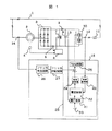
図1は、本発明の一実施形態による誘導機の速度制御装置であり、フリッカを抑制する機能を持った巻線形誘導電動機の速度制御装置の構成を示す。
【0007】
図1において、1は交流電源系統、2は巻線形誘導電動機、3は巻線形誘導電動機2の2次電圧を直流に変換する順変換器(ダイオード整流器)である。4は速度検出器であり、巻線形誘導電動機2の速度を検出し、出力する。5は電流検出器であり、順変換器3の出力電流を検出し、出力する。6は速度制御回路であり、速度検出器4より出力される信号と電流検出器5より出力される信号を入力し、この信号に基づいて自己消弧型素子(IGBT)7をオンオフする制御信号を演算し、出力する。8は逆流阻止用ダイオードであり、自己消弧型素子(IGBT)7がオフ状態の時に順変換器3の出力電流がコンデンサ9に流れる。10は巻線形誘導電動機2の2次電力を交流電源系統1に回生するための逆変換器(IGBTインバータ)、11は逆変換器用変圧器である。12は電流検出器であり、逆変換器10の出力電流を検出し、出力する。13は電圧検出器であり、コンデンサ9の電圧を検出し、出力する。14は電流検出器であり、巻線形誘導電動機2の1次電流を検出し、出力する。15は逆変換器10の制御装置であり、電流検出器12より出力される信号と電圧検出器13より出力される信号と電流検出器14より出力される信号が入力され、この信号に基づいて逆変換器10の制御信号を出力する。
【0008】
尚、順変換器3と自己消弧型素子7の接続点間にリアクトルを挿入してもよい。
【0009】
次に、本実施形態の動作を説明する。まず、誘導電動機の速度制御部分の動作について説明する。速度制御は速度制御回路6にて行われ、速度指令と速度検出器4より出力される信号が一致するように、順変換器3の出力電流指令値を演算し、前記電流指令値と電流検出器5より出力される信号が一致するように、自己消弧型素子7のオンオフ制御信号を出力する。このように、直流電流が制御されるので、巻線形誘導電動機2の2次電流及びトルクは、電流指令に比例するように制御され、従って回転速度は速度指令に追従して制御される。
【0010】
次に、巻線形誘導電動機の2次電力の回生動作について説明する。速度制御回路6にて自己消弧型素子7がオンしている間は、順変換器3の直流出力電流は自己消弧型素子7を通して流れ、このときダイオード8に流れる電流は零となる。また、逆に自己消弧型素子7がオフしている間は、直流出力電流はダイオード8を通して流れる。そして、順変換器3の直流出力電流は、自己消弧型素子7がオンのとき増加し、オフのとき減少する。このようにして、出力電流は速度制御回路6の出力信号に従い制御される。また、ダイオード8を流れる電流はコンデンサ9を充電し、その電圧を高くする。その結果、逆変換器10の制御装置15の動作により、交流電源側に誘導電動機2の2次電力が回生される。ここで、自己消弧型素子7,ダイオード8,コンデンサ9により構成される回路は、すべりにより変化する誘導電動機2の2次電圧を一定電圧の直流に変換する作用があり、このとき、逆変換器10側に伝達される2次電力は一定電圧の直流電力となる。
【0011】
次に、回生動作を行う逆変換器10の制御装置15の構成と動作について説明する。20は電圧指令発生器であり、電圧指令を出力する。21は電圧制御器であり、電圧指令発生器20の出力である電圧指令と電圧検出器13より出力される電圧検出値が入力され、この信号に基づいて直流電流指令信号を演算し、出力する。22は電流制御器であり、該電流指令信号と座標変換器23より出力される電流検出信号が入力され、この信号に基づいて電圧指令信号を出力する。ここで、23は交流を電源電圧位相を基準に座標変換する座標変換器であり、電流検出器12からの交流電流検出信号が入力され、座標変換演算を行い、2軸電流信号(有効電流と無効電流検出信号)を出力する。また、24は電圧指令を交流に変換する座標変換器であり、電流制御器22からの電圧指令信号が入力され、座標変換演算を行い、交流電圧指令信号を出力する。25はPWM制御器であり、前記交流電圧指令信号とPWMキャリア信号を比較し、逆変換器10の自己消弧型素子のオンオフ制御信号を出力する。ここで、28は平滑コンデンサ電圧制御器であり、電圧指令発生器20,電圧制御器21,電流制御器22,座標変換器23,座標変換器24により構成され、平滑コンデンサ電圧が電圧指令発生器20からの電圧指令に一致するような電圧指令信号を出力する。
【0012】
順変換器3の直流出力電流は、ダイオード8を通して流れ、コンデンサ9を充電し、その電圧を高くする。電圧指令発生器20は、コンデンサ9の両端電圧の指令信号を出力し、コンデンサ9の両端電圧がこれより高くなると、電圧制御器からの電流指令が増大し、これにより逆変換器10の入力電流が増加するため、コンデンサ9の両端電圧が一定になるように制御される。この電流制御は、電圧制御ループの内側にある電流制御ループにより行われる。すなわち、逆変換器10の出力電流は、電流検出器12により検出され、座標変換器23を介した後、前記電流指令信号と共に電流制御器22に入力され、これにより、逆変換器10の出力電流は電流指令値に一致するように制御される。この結果、入力電流が電流指令に従い制御される。また、前記電圧指令信号はPWM制御器25に入力され、ここでPWM制御により逆変換器10の自己消弧型素子をオンオフ制御することによって逆変換器10の出力電圧を制御し、逆変換器10の出力電流を制御する。このように、コンデンサ9の電圧が指令電圧より高くなると、コンデンサ電圧が指令電圧に一致するように逆変換器の出力電圧と出力電流が制御される。従って、自己消弧型素子7,ダイオード8,コンデンサ9により構成される回路により、直流に変換された誘導電動機2の2次電力は、逆変換器10から電源側に回生される。以上が従来技術の説明である。
【0013】
次に、本発明の実施形態について述べる。誘導電動機2の1次側にフリッカが発生するため、本実施形態では、前記逆変換器10に前記フリッカを抑制する機能を付加することで、フリッカを抑制できる誘導機の速度制御装置を構成している。即ち、誘導電動機2の1次側電流を電流検出器14で検出し、該検出信号をフリッカ検出回路26に入力する。該検出回路26は、入力された信号に含まれるフリッカ成分を抽出し、出力する。該検出回路26より出力されるフリッカ成分の信号は、フリッカ抑制制御器27に入力され、該制御器27は、入力されたフリッカ成分が零となるような電圧指令信号を演算し出力する。前記制御器27より出力される電圧指令信号は、平滑コンデンサ電圧制御器28より出力される電圧指令信号と合成され、PWM制御器25に入力される。従って、誘導電動機2から電源系統1に流出するフリッカ成分を相殺するように逆変換器10の出力電流が制御され、本実施形態によれば、新たな装置を追加することなく、フリッカを抑制できる。
【0014】
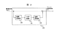
図2は、図1のフリッカ検出回路26の一実施形態を示したものである。図2において、30は座標変換器であり、電流検出器14より出力される誘導電動機2の1次側3相交流電流を電源電圧位相を基準に座標変換し、2軸電流信号を出力する。31はフィルタ回路であり、該信号が入力され、直流以外の成分が除去された信号を出力する。32は座標変換器であり、フィルタ回路31より出力される直流信号を3相交流電流に座標変換した信号を出力する。ここで、誘導電動機2の1次側3相交流電流の基本波成分は座標変換器30により、直流に変換され、フィルタ回路31を通すことで直流以外の成分が除去される。そして、座標変換器32により再び交流信号に座標変換することで、座標変換器32の出力信号には、誘導電動機2の1次電流の基本波成分のみが抽出される。さらに、電流検出器14より出力される誘導電動機2の1次側3相交流電流から前記基本波成分を差し引くことで、基本波以外の成分を抽出し、抽出された信号はフリッカ抑制制御器27へ入力される。尚、フリッカ成分(数Hz〜30Hz程度)のみを抽出するため、フリッカ成分の周波数より高域の周波数成分を除去するフィルタ回路を付加してもよい。
【0015】
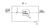
図3は、図1のフリッカ抑制制御器27の一実施形態を示したものである。図3において、33は比例制御器であり、フリッカ検出回路26より出力されるフリッカ検出信号を零信号から差し引いた偏差信号が入力され、入力された偏差信号が零となるような電圧指令信号を出力する。出力された電圧指令信号は、座標変換器24からの電圧指令信号と合成され、PWM制御器25に入力される。ここで、比例制御器33は、入力されたフリッカ成分が零となるような電圧指令信号を演算し、逆変換器10の出力電流を制御する。尚、比例制御器33を比例積分制御器などとしてもよく、また、フリッカ検出信号より直接電圧指令を演算するフィードフォワード制御器を付加してもよい。
【0016】
尚、本発明を同様の制御装置を備えた巻線形誘導発電機システムに対して適用しても同様の効果が得られる。
【0017】
【発明の効果】
以上説明したように、本発明によれば、誘導機の1次電流よりフリッカ成分を抽出し、該成分を抑制するように、逆変換器の出力電流を制御する回路構成としたので、新たな装置を追加することなく、フリッカを抑制できる誘導機の速度制御装置が得られる。
【図面の簡単な説明】
【図1】本発明の一実施形態を示す誘導機の速度制御装置の構成図。
【図2】本発明のフリッカ検出回路の一実施形態を示す構成図。
【図3】本発明のフリッカ抑制制御器の一実施形態を示す構成図。
【符号の説明】
1…交流電源系統、2…巻線形誘導電動機、3…順変換器、4…速度検出器、5…電流検出器、6…速度制御回路、7…自己消弧型素子、8…ダイオード、9…コンデンサ、10…逆変換器、11…逆変換器用変圧器、12,14…電流検出器、13…電圧検出器、15…逆変換器の制御装置、20…電圧指令発生器、21…電圧制御器、22…電流制御器、23,24…座標変換器、25…PWM制御器、26…フリッカ検出回路、27…フリッカ抑制制御器、28…平滑コンデンサ電圧制御器。[0001]
BACKGROUND OF THE INVENTION
The present invention relates to an induction machine speed control device using a Serbius system that controls secondary power of an induction machine using a chopper and a regenerative inverter, and more particularly to a technique for suppressing flicker.
[0002]
[Prior art]
Speed control of an induction machine in which an induction machine capable of secondary excitation and a forward converter connected to the secondary side of the induction machine are connected to an inverse converter that regenerates electric power from the forward converter to an AC power source. The device is known by the name of the Serbius system. In this case, due to the characteristics of the forward converter (diode rectifier), the AC side current, that is, the secondary winding current of the motor is distorted, so that the motor primary current is less related to the slip of the motor. There is a case where the reactive current fluctuates, and this may cause flickering in the fluorescent lamp connected to the power supply system.
[0003]
[Problems to be solved by the invention]
The subject of this invention is providing the control apparatus of the induction machine which can suppress a flicker in view of the said situation.
[0004]
[Means for Solving the Problems]
In order to solve the above problem, a flicker component is extracted from the primary current detection signal of the induction machine, and the output current of the inverse converter is controlled so as to suppress this component.
[0005]
DETAILED DESCRIPTION OF THE INVENTION
Hereinafter, embodiments of the present invention will be described with reference to the drawings.
[0006]
FIG. 1 shows an induction machine speed control apparatus according to an embodiment of the present invention, and shows a configuration of a speed control apparatus for a winding induction motor having a function of suppressing flicker.
[0007]
In FIG. 1, 1 is an AC power supply system, 2 is a winding induction motor, and 3 is a forward converter (diode rectifier) that converts a secondary voltage of the
[0008]
A reactor may be inserted between the connection points of the
[0009]
Next, the operation of this embodiment will be described. First, the operation of the speed control part of the induction motor will be described. The speed control is performed by the
[0010]
Next, the regenerative operation of the secondary power of the winding induction motor will be described. While the self-extinguishing element 7 is on in the
[0011]
Next, the configuration and operation of the
[0012]
The DC output current of the
[0013]
Next, an embodiment of the present invention will be described. Since flicker is generated on the primary side of the
[0014]
FIG. 2 shows an embodiment of the
[0015]
FIG. 3 shows an embodiment of the
[0016]
It should be noted that the same effect can be obtained even when the present invention is applied to a wound induction generator system having a similar control device.
[0017]
【The invention's effect】
As described above, according to the present invention, since the flicker component is extracted from the primary current of the induction machine and the output current of the inverse converter is controlled so as to suppress the component, a new circuit configuration is provided. A speed control device for an induction machine that can suppress flicker without adding a device is obtained.
[Brief description of the drawings]
FIG. 1 is a configuration diagram of a speed control device for an induction machine showing an embodiment of the present invention.
FIG. 2 is a configuration diagram showing an embodiment of a flicker detection circuit of the present invention.
FIG. 3 is a block diagram showing an embodiment of a flicker suppression controller of the present invention.
[Explanation of symbols]
DESCRIPTION OF SYMBOLS 1 ... AC power supply system, 2 ... Winding type induction motor, 3 ... Forward converter, 4 ... Speed detector, 5 ... Current detector, 6 ... Speed control circuit, 7 ... Self-extinguishing element, 8 ... Diode, 9 DESCRIPTION OF SYMBOLS Capacitor, 10 ... Inverter, 11 ... Inverter transformer, 12, 14 ... Current detector, 13 ... Voltage detector, 15 ... Inverter control device, 20 ... Voltage command generator, 21 ... Voltage Controller, 22 ... Current controller, 23, 24 ... Coordinate converter, 25 ... PWM controller, 26 ... Flicker detection circuit, 27 ... Flicker suppression controller, 28 ... Smoothing capacitor voltage controller.
Claims (4)
誘導機の1次電流検出信号からフリッカの原因となる高調波成分を抽出し、該高調波成分を相殺するように、前記逆変換器の出力電流を制御することを特徴とする誘導機の速度制御装置。The speed of the induction machine that controls the speed while connecting the secondary side of the induction machine capable of secondary excitation to the forward converter and regenerating the secondary power of the induction machine from the forward converter to the AC power source by the inverse converter. In the control device,
Speed of the induction machine for extracting harmonic components from the primary current detection signal of the induction machine causes flicker, so as to cancel the high-harmonic components, and controls the output current of the inverter Control device.
誘導機の1次電流検出信号からフリッカの原因となる高調波成分を抽出し、該高調波成分を相殺するように、前記逆変換器の出力電流を制御することを特徴とする誘導機の速度制御装置。A self-extinguishing element is connected directly or via a reactor between an induction machine capable of secondary excitation and a DC output terminal of a forward converter connected to the secondary side of the induction machine, In a speed control device for an induction machine in which a series circuit of a diode and a capacitor is connected in parallel, and an inverse converter is connected between the terminals of the capacitor, and the secondary power of the induction machine is regenerated to an AC power source and speed control is performed. ,
Speed of the induction machine for extracting harmonic components from the primary current detection signal of the induction machine causes flicker, so as to cancel the high-harmonic components, and controls the output current of the inverter Control device.
Priority Applications (1)
| Application Number | Priority Date | Filing Date | Title |
|---|---|---|---|
| JP2000203044A JP3772649B2 (en) | 2000-06-30 | 2000-06-30 | Induction machine speed control device |
Applications Claiming Priority (1)
| Application Number | Priority Date | Filing Date | Title |
|---|---|---|---|
| JP2000203044A JP3772649B2 (en) | 2000-06-30 | 2000-06-30 | Induction machine speed control device |
Publications (2)
| Publication Number | Publication Date |
|---|---|
| JP2002027789A JP2002027789A (en) | 2002-01-25 |
| JP3772649B2 true JP3772649B2 (en) | 2006-05-10 |
Family
ID=18700492
Family Applications (1)
| Application Number | Title | Priority Date | Filing Date |
|---|---|---|---|
| JP2000203044A Expired - Fee Related JP3772649B2 (en) | 2000-06-30 | 2000-06-30 | Induction machine speed control device |
Country Status (1)
| Country | Link |
|---|---|
| JP (1) | JP3772649B2 (en) |
Families Citing this family (2)
| Publication number | Priority date | Publication date | Assignee | Title |
|---|---|---|---|---|
| JP4549159B2 (en) * | 2004-11-05 | 2010-09-22 | 東芝三菱電機産業システム株式会社 | Winding induction motor controller |
| WO2011105676A1 (en) * | 2010-02-24 | 2011-09-01 | 주식회사 자이벡 | Apparatus and method for controlling the speed of a wound-rotor induction motor |
-
2000
- 2000-06-30 JP JP2000203044A patent/JP3772649B2/en not_active Expired - Fee Related
Also Published As
| Publication number | Publication date |
|---|---|
| JP2002027789A (en) | 2002-01-25 |
Similar Documents
| Publication | Publication Date | Title |
|---|---|---|
| JP3248153B2 (en) | Multi-level power converter | |
| RU2483424C1 (en) | Device of power conversion | |
| JP4549159B2 (en) | Winding induction motor controller | |
| JP2624793B2 (en) | Control device for PWM boost converter | |
| JP2009060723A (en) | Control device for power conversion device and stationary auxiliary power supply device for vehicle | |
| JP3772649B2 (en) | Induction machine speed control device | |
| JP3249709B2 (en) | Inverter device | |
| JP2003189631A (en) | Power failure detection device for power converter circuit | |
| JP3675124B2 (en) | Control device for pulse width modulation control converter | |
| JP2005304248A (en) | Motor drive inverter control device and electrical equipment | |
| JPH10164845A (en) | Pwm rectifier | |
| KR100758979B1 (en) | Regenerative inverter device for DC train and control method thereof | |
| JPH10164846A (en) | Control device for power conversion apparatus | |
| JP4478303B2 (en) | Inverter parallel operation device | |
| JP2004080855A (en) | Power converter | |
| JPH09289776A (en) | Inverter circuit of power supply | |
| JPS5819169A (en) | Controlling method for pwm control converter | |
| JP3643895B2 (en) | Electric vehicle control device | |
| JPH11225477A (en) | Sine wave converter with filtering function | |
| JP3341047B2 (en) | Multi-level power converter | |
| JP3524626B2 (en) | Static power converter | |
| JP3706188B2 (en) | Active filter | |
| JPH0487592A (en) | Speed controller for wound-rotor type induction motor | |
| JP4895965B2 (en) | Auxiliary power supply for vehicle | |
| JPH06209579A (en) | Power converter |
Legal Events
| Date | Code | Title | Description |
|---|---|---|---|
| A621 | Written request for application examination |
Free format text: JAPANESE INTERMEDIATE CODE: A621 Effective date: 20040816 |
|
| A977 | Report on retrieval |
Free format text: JAPANESE INTERMEDIATE CODE: A971007 Effective date: 20051109 |
|
| A131 | Notification of reasons for refusal |
Free format text: JAPANESE INTERMEDIATE CODE: A131 Effective date: 20051115 |
|
| A521 | Written amendment |
Free format text: JAPANESE INTERMEDIATE CODE: A523 Effective date: 20051226 |
|
| TRDD | Decision of grant or rejection written | ||
| A01 | Written decision to grant a patent or to grant a registration (utility model) |
Free format text: JAPANESE INTERMEDIATE CODE: A01 Effective date: 20060124 |
|
| A61 | First payment of annual fees (during grant procedure) |
Free format text: JAPANESE INTERMEDIATE CODE: A61 Effective date: 20060206 |
|
| FPAY | Renewal fee payment (event date is renewal date of database) |
Free format text: PAYMENT UNTIL: 20090224 Year of fee payment: 3 |
|
| FPAY | Renewal fee payment (event date is renewal date of database) |
Free format text: PAYMENT UNTIL: 20100224 Year of fee payment: 4 |
|
| FPAY | Renewal fee payment (event date is renewal date of database) |
Free format text: PAYMENT UNTIL: 20100224 Year of fee payment: 4 |
|
| FPAY | Renewal fee payment (event date is renewal date of database) |
Free format text: PAYMENT UNTIL: 20110224 Year of fee payment: 5 |
|
| FPAY | Renewal fee payment (event date is renewal date of database) |
Free format text: PAYMENT UNTIL: 20120224 Year of fee payment: 6 |
|
| FPAY | Renewal fee payment (event date is renewal date of database) |
Free format text: PAYMENT UNTIL: 20120224 Year of fee payment: 6 |
|
| FPAY | Renewal fee payment (event date is renewal date of database) |
Free format text: PAYMENT UNTIL: 20130224 Year of fee payment: 7 |
|
| FPAY | Renewal fee payment (event date is renewal date of database) |
Free format text: PAYMENT UNTIL: 20130224 Year of fee payment: 7 |
|
| LAPS | Cancellation because of no payment of annual fees |