JP3772619B2 - Hydrogen generator - Google Patents
Hydrogen generator Download PDFInfo
- Publication number
- JP3772619B2 JP3772619B2 JP37385999A JP37385999A JP3772619B2 JP 3772619 B2 JP3772619 B2 JP 3772619B2 JP 37385999 A JP37385999 A JP 37385999A JP 37385999 A JP37385999 A JP 37385999A JP 3772619 B2 JP3772619 B2 JP 3772619B2
- Authority
- JP
- Japan
- Prior art keywords
- unit
- temperature
- reforming
- reduction
- removal
- Prior art date
- Legal status (The legal status is an assumption and is not a legal conclusion. Google has not performed a legal analysis and makes no representation as to the accuracy of the status listed.)
- Expired - Lifetime
Links
Images
Classifications
-
- Y—GENERAL TAGGING OF NEW TECHNOLOGICAL DEVELOPMENTS; GENERAL TAGGING OF CROSS-SECTIONAL TECHNOLOGIES SPANNING OVER SEVERAL SECTIONS OF THE IPC; TECHNICAL SUBJECTS COVERED BY FORMER USPC CROSS-REFERENCE ART COLLECTIONS [XRACs] AND DIGESTS
- Y02—TECHNOLOGIES OR APPLICATIONS FOR MITIGATION OR ADAPTATION AGAINST CLIMATE CHANGE
- Y02E—REDUCTION OF GREENHOUSE GAS [GHG] EMISSIONS, RELATED TO ENERGY GENERATION, TRANSMISSION OR DISTRIBUTION
- Y02E60/00—Enabling technologies; Technologies with a potential or indirect contribution to GHG emissions mitigation
- Y02E60/30—Hydrogen technology
- Y02E60/50—Fuel cells
Landscapes
- Hydrogen, Water And Hydrids (AREA)
- Fuel Cell (AREA)
Description
【0001】
【発明の属する技術分野】
本発明は、天然ガス、LPG、ガソリン、ナフサ、灯油、メタノール等炭化水素系物質と水とを原料として、燃料電池等の水素利用機器に供給するための水素を発生する装置に関する。
【0002】
【従来の技術】
化石燃料に替わるエネルギー源の有力候補の一つとして水素が注目されているが、その有効利用のためには水素パイプライン等社会インフラの整備が必要とされている。その一つの方法として、天然ガス、その他化石燃料、アルコール等現状既に構築されている運送、搬送等のインフラを利用し、水素を必要とする場所でそれら燃料を改質して水素を発生させる方法が検討されている。例えば中小規模でのオンサイト発電装置としての燃料電池のための天然ガス(都市ガス)改質技術、自動車の動力源用の燃料電池のためのメタノール改質技術等が様々な形で提案されている。それらの原料を改質して水素を発生させるためには高温での触媒反応が用いられ、代表的な方法として部分酸化法、水蒸気改質法、両者を併用したオートサーマル法と呼ばれる方法がある。しかし、改質反応は高温で進行するため、生成物としての水素とともにその反応平衡から副生成物として一酸化炭素(以下COと記述)、二酸化炭素(以下CO2と記述)が生成する。生成した水素を燃料電池に適用するとき、特に高分子型燃料電池においては、副生成物であるCOは燃料電池の電極を被毒してその性能を著しく劣化させるため、極力低濃度にしておく必要がある。そのため、改質反応部の下流側にCO濃度を低減するCO低減部を設置し、CO濃度を数十ppmにまで低下させる方法を採用するのが一般的である。CO低減部は通常、変成反応部、CO除去部から構成され順次CO濃度を低減させる。この一連の反応で、改質部で生成される10%程度の濃度のCOは、変成部で1%前後まで低減され、さらにCO除去部で数十ppmまで低減され、燃料電池に供給されることになる。
【0003】
【発明が解決しようとする課題】
燃料電池特に高分子型燃料電池に水素を供給するための水素発生器は従来例に示したように、改質反応、変成反応、CO除去反応を経由するのが一般的であり、改質反応用にはニッケル等のベースメタルあるいはルテニウム等の貴金属が、変成反応用には銅系のベースメタルあるいは白金等の貴金属が、CO除去部には白金等の貴金属が触媒として用いられていた。このとき、それぞれの反応部位で確実な反応を進行させるために上記触媒の温度は、一定範囲内に厳密に制御する必要があった。すなわち、改質反応部、変成反応部の反応は触媒の活性が十分な状態であれば、一定の圧力状態の下でほぼ温度だけで一義的に組成等が決定される平衡反応であり、CO除去部の反応も平衡反応的な外乱要素を含む反応である事に起因しているためである。したがって、水素発生装置を一定量の水素を発生させる定常状態においても、発生量を変化させる等の過渡状態においても安定に運転させ、副生物も含め一定の組成で利用機器に供給するためには、各反応部の温度を可及的に一定に保持することが最も重要なポイントであった。特に発生量を変化させたときには各部の温度が変化し易く、発生量の変化幅を大きく取りたい場合の最も大きな阻害要因であった。
【0004】
本発明はそれらの点に鑑みて成されたものであり、全体は従来とほぼ同様に構成されるが、各反応部の温度検知の場所とそれに対応する具体的な温度制御の方策を提案して、確実な動作が得られる操作性、利便性に優れた水素発生装置を提供することを目的としたものである。
【0005】
【課題を解決するための手段】
上記課題を解決するために本発明は、少なくとも炭素原子を含有する燃料と水蒸気とを改質反応させる改質部と、前記改質部に設けた改質温度検知部と、前記改質温度検知部よりも反応物流れ方向における上流側に設けた、前記改質部を加熱する加熱部と、前記改質部の改質反応で副生された一酸化炭素濃度を低減するためのCO低減部と、前記CO低減部の温度を検知するCO低減温度検知部と、前記CO低減温度検知部よりも反応物流れ方向における上流側に設けた、前記CO低減部を冷却するCO低減冷却部と、を設け、前記改質温度検知部の検知温度に基づき、前記加熱部の加熱量を増減して前記改質部の温度を制御し、前記CO低減温度検知部の検知温度に基づき、前記CO低減冷却部の冷却量を増減して前記CO低減部の温度を制御することを特徴とする水素発生装置である。
【0006】
また、本発明の水素生成装置においては、前記CO低減部は少なくともCO変成部とCO除去部とから成り、前記CO変成部にCO変成冷却部とCO変成温度検知部を、前記CO除去部にCO除去冷却部とCO除去温度検知部を設け、前記CO低減温度検知部が、前記CO変成温度検知部と前記CO除去温度検知部であることを特徴とする。
【0007】
また、本発明の水素生成装置においては、前記CO変成部を多段に構成し、各段毎に前記CO変成冷却部と前記CO変成温度検知部とを設けたことを特徴とする。
【0008】
また、本発明の水素生成装置においては、前記CO除去部を多段に構成し、各段毎に前記CO除去冷却部と前記CO除去温度検知部とを設けたことを特徴とする。
【0009】
また、本発明の水素生成装置においては、前記改質温度検知部を前記改質部の出口部ま
たはその近傍に設け、前記CO低減温度検知部を前記CO低減部の出口部またはその近傍に設けたことを特徴とする。
【0010】
また、本発明の水素生成装置においては、前記改質温度検知部を前記改質部の出口部またはその近傍に設け、前記CO変成温度検知部および前記CO除去温度検知部をそれぞれ前記CO変成部および前記CO除去部の出口部またはその近傍に設けたことを特徴とする。
【0011】
また、本発明の水素生成装置においては、前記CO低減冷却部で回収した熱を少なくとも改質部を含む装置内に流入する流体に伝熱させることを特徴とする。
【0012】
また、本発明の水素生成装置においては、前記CO変成冷却部および前記CO除去冷却部で回収した熱を少なくとも改質部を含む装置内に流入する流体に伝熱させることを特徴とする。
【0013】
【発明の実施の形態】
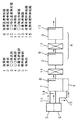
図1は本発明による水素発生装置の第1の実施の形態の流路図を示す。本装置は水蒸気改質反応を利用した方式であり、燃料と水蒸気を反応させて水素を発生させる。1は内部に改質触媒を充填した改質部であり、2は変成触媒を充填した変成部、3はCO除去触媒を充填したCO除去部である。変成部2およびCO除去部3とでCO低減部4を構成している。5は水蒸気改質の原料である水蒸気の供給部であり、水蒸気供給路13を介して改質部1へ水蒸気を供給する。6は燃料の供給部であり、燃料は加熱用燃料供給路15を介して加熱部7と、改質用燃料供給路14を介して改質部1へと送られる。加熱部7では加熱用燃料供給路15を介して燃料供給部6から送られてきた燃料を燃焼させ、燃焼熱によって改質部1を加熱する。8は反応部流れ方向において改質部1の下流側出口近傍に設けた改質温度検知器、9は変成部2の下流側出口近傍に設けた変成温度検知器、10はCO除去部3の下流側出口近傍に設けたCO除去温度検知器であり、それぞれの反応部で反応した後のガス流体の温度を検知する。11は変成部2の上流側に設けた変成冷却器、12はCO除去部3の上流側に設けたCO除去冷却器である。改質部1、変成部2、CO除去部3の各部にはそれぞれ触媒が設置されている。ここではそれぞれの部位に触媒種として全部貴金属系触媒を用いているが、用途、目的等によりベースメタル系触媒を選択しても良い。また、触媒を担持する担体は形状として粒状、ペレット状、ハニカム状等から、材質はセラミック、耐熱性金属等から適宜選択できるものであり、ここではセラミックハニカム状担体にウォッシュコート層を形成して、その上に貴金属を担持して構成している。貴金属は白金、ロジウム、パラジウム、イリジウム等から適宜選択可能であるが、ここではすべての部位に白金を主体とした触媒を用いた。燃料は天然ガス(都市ガス)、LPG等の気体状炭化水素燃料あるいはガソリン、灯油、メタノール等の液体状炭化水素系燃料が用いられる。ただし、液体状燃料を用いるときには燃料の気化部が必要となるが、気化用の熱は改質部出口ガスの顕熱、燃料電池のテールガス中の水素等の未燃ガスを燃焼させた燃焼熱等システム内の廃熱を用いると装置全体として効率的な運転が可能となる。また、メタノールを燃料に用いたときのCO低減部4はCO除去部3だけで対応可能であり、変成部2は省略できる。もう一方の原料である水は水蒸気の状態にして水蒸気供給部5から改質部1へ供給されるが、気化用の熱は別途必要であり、上記に示した液体燃料気化用に示したような方法が効率的である。ここでは改質出口ガスの顕熱を用いているが図中その構成は省略する。図中矢印は原料物質、反応物質、生成物質等の流れ方向を示している。改質温度検知器8、変成温度検知器9、CO除去温度検知器10は、ここでは熱電対を用いているが、サーミスタ等を用いることも当然可能である。
【0014】
ここで示す実施の形態において、水素の発生方法としては水蒸気改質方式を用いている。それぞれの反応部での温度制御方法について説明する。改質部1で進行する水蒸気改質反応は吸熱反応であるので、必要な吸熱反応分の熱は加熱部7の燃焼熱で補う。炭化水素系燃料を用いた場合、温度は650℃〜750℃の範囲が適切であるが、改質部1の構成あるいは燃料と水蒸気との混合割合等の条件で幾分最適値は変化する。通常上記温度範囲の中で最適温度に対して±20℃程度の範囲内に制御することが望ましい。ここでは改質温度検知器8の検知温度に応じて加熱部7の燃焼量を増減させて改質部1の温度を一定に制御する。改質反応の吸熱量は大きいため、加熱量の増減による改質部1の温度は比較的敏感に反応して変化する。このとき、改質反応自体が可逆反応であるので改質反応後の生成ガスの組成は出口付近の温度による平衡でほぼ一義的に決定される。したがって出口付近の温度が反応を制御する観点から重要であり、その温度を基に加熱量を制御することで、改質部1の性能を最適に保つことが可能となる。
【0015】
次に変成部2に付いて説明する。変成部2は触媒種類に何を用いるかによって最適温度が異なるが、ここでの反応も基本的には改質部1と同様に可逆反応であるので、改質部1の場合と同様に、温度を何度に制御するかが極めて重要であり、制御温度の平衡によって出口組成がほぼ決定されることになる。一般に反応温度は200℃〜300℃程度に制御される。ただ、改質部1の場合と異なるのは反応が発熱反応である点である。したがって、反応物の流れ方向の下流側に行くにしたがい反応が進行し、反応物の温度が上昇することになる。変成部2の温度を一定に保つためにその途中で冷却することも可能であるが、条件によって反応位置がずれることがあるため適切な冷却は困難となる。本実施の形態においては、変成温度検知器9によって下流側の温度を検知することでオーバーオールの変成部2の状態が把握できるため、その温度を基準として適切な冷却量を把握することが可能となる。このとき、変成冷却器11を上流側に設けておけば入口部を冷却でき、変成部2全体を通して最も温度が高い位置は下流側となるため、反応平衡をその温度以下に設定でき、目的とする反応物組成、特に目的とするCO濃度の生成物を得ることが可能となる。
【0016】
次にCO除去部3について説明する。CO除去部3でCOを低減する方式として選択酸化方式と、メタン化反応方式が知られている。選択酸化反応方式では触媒前に少量の空気を混入させ、COを選択的に酸化してその濃度を減じる。メタン化反応方式ではCOを水素と反応させてその濃度を減じる。本実施の形態では選択反応方式を用いているが、図1中に空気の導入口は省略する。どちらの方式も発熱反応であるため、CO除去部の温度分布は、変成部2のときと同様に入口側に比べて出口側の方が高温となる。一般に反応温度は100℃〜200℃程度の間で操作されるが、使用する触媒、操作方法等の条件の相違で最適温度範囲は多少異なる。しかしいずれにしても、副反応として誘引される逆シフト反応によるCO濃度の増加、過度のメタン化反応による水素濃度の減少を回避するために、出口温度を適正に制御する必要が生じる。したがって、反応器の下流側出口温度を検知しながらその上流の冷却操作で反応部温度をコントロールすることが最も有効な反応部の温度制御方法となる。ここでは、反応部出口近傍に設けたCO除去温度検知器10の検知温度を基に、CO除去部3の上流側に設けたCO除去冷却部12の冷却量を増減しながらCO除去部3の温度を適正に制御する構成としている。この構成で、定常時は当然ながら外乱等により各反応部の温度が変化したときも迅速に対応が可能となり、各反応部温度を適正範囲内に制御することが可能となった。また、水素の発生量を変化させるときには、燃料の供給量および水蒸気の供給量をまず変化させることになるが、それに準じて加熱部7の加熱量を瞬間的に変化させるとともに、その後もそれぞれの反応部の検知温度に基づいて改質器1下流側の冷却量をこまめに変化させることで各反応部の温度を適正範囲内に保つことが可能となった。運転結果では、水素発生量を最大発生量から1/3の量に変化させた場合にも、その逆の操作を行なった場合でも、各反応部の温度変化は30℃以内に制御可能であった。その時の発生水素中のCO濃度は5〜15ppmの範囲内の変化に収まり、本実施の形態での構成および操作の有効性が確認された。
【0017】
変成冷却器11、CO除去冷却器12は数百度の部分を冷却することになるので、熱回収器として用いる事もできる。その場合、回収した熱は原料等に伝熱して装置内に還流させることで装置の熱効率を向上させる事ができる。すなわち、装置内に導入する流体、燃料(改質用、燃焼用)、水または水蒸気、燃焼用空気がその対象となる。それらは通常室温レベルまたはそれに近い温度で装置内に導入させるので、上記冷却部で回収した数百度レベルの熱で容易に熱交換可能である。
【0018】
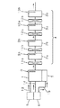
図2は本発明による別の実施の形態を示す水素発生器の流路図である。図1と重複する部分については同番号で示し、その説明を省略する。図1における実施の形態との相違点は、CO低減部4を構成する変成部2およびCO除去部3をそれぞれ、第1変成部2a、第2変成部2b、第1CO除去部3a、第2CO除去部2bと2段に構成した点である。ここでは2段の構成としているが、必要に応じてさらに多段に構成できることは言うまでもないことである。この構成に応じて変成冷却器11は第1変成冷却器11a、第2変成冷却器11bと2段に、変成温度検知器9も第1変成温度検知器9a、第2変成温度検知器9bと2個設け、CO除去冷却器12は第1CO除去冷却器12a、第2CO除去冷却器12bと2段とし、CO除去温度検知器10も第1CO除去温度検知器10a、第2CO除去温度検知器10bと2個設けて構成した。この構成で第1変成温度検知器9aの検知温度を基に第1変成冷却器11aの冷却量を増減し、第2変成温度検知器9bの検知温度を基に第2変成冷却器11bの冷却量を増減し、第1CO除去温度検知器10aの検知温度を基に第1CO除去冷却器12aの冷却量を増減し、第2CO除去温度検知器10bの検知温度を基に第2CO除去冷却器12bの冷却量を増減することにより、全体としての変成部、CO浄化部の温度をより精密に制御することが可能となり、水素発生器としての性能もより向上することになる。第1変成冷却器11a、第2変成冷却器11b、第1CO除去冷却器12a、第2CO除去冷却器12bで熱回収して装置内に還流し、装置の熱効率を向上させることが可能である点は図1に示す実施の形態と同様であることは言うまでもないことである。
【0019】
【発明の効果】
本発明では触媒反応を利用した改質部、CO低減部(変成部およびCO除去部)の下流側近傍に温度検知器を設置し、改質部においてはその温度検知器の検知温度に基づいて改質部の加熱量を増減することにより、また、CO除去部においてはその検知温度に基づいてその上流側に設けた冷却器の冷却量を増減することで各反応部の適正な温度制御を可能とし、確実で信頼性の高いガス生成を可能とする水素発生装置を提供することを可能としたものである。
【図面の簡単な説明】
【図1】本発明による水素発生装置の実施の形態を示す流路図
【図2】本発明による水素発生装置の別の実施の形態を示す流路図
【符号の説明】
1 改質部
2 変成部
2a 第1変成部
2b 第2変成部
3 CO除去部
3a 第1CO除去部
3b 第2CO除去部
4 CO低減部
5 水蒸気供給部
6 燃料供給部
7 加熱部
8 改質温度検知器
9 変成温度検知器
9a 第1変成温度検知器
9b 第2変成温度検知器
10 CO除去温度検知器
10a 第1CO除去温度検知器
10b 第2CO除去温度検知器
11 変成冷却器
11a 第1変成冷却器
11b 第2変成冷却器
12 CO除去冷却器
12a 第1CO除去冷却器
12b 第2CO除去冷却器
13 水蒸気供給路
14 改質用燃料供給路
15 加熱用燃料供給路[0001]
BACKGROUND OF THE INVENTION
The present invention relates to an apparatus for generating hydrogen to be supplied to a hydrogen-using device such as a fuel cell using water and a hydrocarbon-based material such as natural gas, LPG, gasoline, naphtha, kerosene, and methanol as raw materials.
[0002]
[Prior art]
Hydrogen is attracting attention as one of the promising energy sources to replace fossil fuels, but social infrastructure such as hydrogen pipelines is required for its effective use. One method is to use natural gas, other fossil fuels, alcohol, and other infrastructure that has already been built, such as transportation and transportation, and reform these fuels where hydrogen is needed to generate hydrogen. Is being considered. For example, natural gas (city gas) reforming technology for fuel cells as small-scale on-site power generation devices, methanol reforming technology for fuel cells for automobile power sources, etc. have been proposed in various forms. Yes. Catalytic reactions at high temperatures are used to reform these raw materials to generate hydrogen, and typical methods include a partial oxidation method, a steam reforming method, and a method called autothermal method using both in combination. . However, since the reforming reaction proceeds at a high temperature, (described as less CO) with hydrogen as a product from the reaction equilibrium carbon monoxide as a by-product, carbon dioxide (hereinafter CO 2 and description) is generated. When the generated hydrogen is applied to a fuel cell, especially in a polymer fuel cell, CO, which is a by-product, poisons the electrode of the fuel cell and significantly deteriorates its performance, so the concentration is kept as low as possible. There is a need. For this reason, it is common to employ a method of installing a CO reduction unit for reducing the CO concentration downstream of the reforming reaction unit and reducing the CO concentration to several tens of ppm. The CO reduction unit is usually composed of a shift reaction unit and a CO removal unit, and sequentially reduces the CO concentration. In this series of reactions, about 10% concentration of CO produced in the reforming unit is reduced to around 1% in the transformation unit, and further reduced to several tens of ppm in the CO removal unit, and supplied to the fuel cell. It will be.
[0003]
[Problems to be solved by the invention]
As shown in the prior art, a hydrogen generator for supplying hydrogen to a fuel cell, particularly a polymer fuel cell, generally passes through a reforming reaction, a shift reaction, and a CO removal reaction. A base metal such as nickel or a noble metal such as ruthenium is used as a catalyst, a copper base metal or a noble metal such as platinum is used as a catalyst for a metamorphic reaction, and a noble metal such as platinum is used as a catalyst in a CO removal section. At this time, the temperature of the catalyst had to be strictly controlled within a certain range in order to allow a reliable reaction to proceed at each reaction site. That is, the reaction in the reforming reaction section and the shift reaction section is an equilibrium reaction in which the composition and the like are uniquely determined only by temperature under a certain pressure condition if the activity of the catalyst is sufficient. This is because the reaction of the removal portion is caused by the reaction including a disturbance element that is an equilibrium reaction. Therefore, in order to supply a hydrogen generator with a constant composition, including by-products, in a steady state in which a hydrogen generator generates a certain amount of hydrogen and in a transient state where the amount of generation is changed, etc. The most important point was to keep the temperature of each reaction part as constant as possible. In particular, when the amount of generation was changed, the temperature of each part was likely to change, and this was the greatest impediment when it was desired to increase the amount of change in the amount of generation.
[0004]
The present invention has been made in view of these points, and the whole is configured in the same manner as in the prior art. However, the temperature detection location of each reaction unit and a specific temperature control method corresponding to it are proposed. Thus, an object of the present invention is to provide a hydrogen generator excellent in operability and convenience in which a reliable operation can be obtained.
[0005]
[Means for Solving the Problems]
In order to solve the above-described problems , the present invention provides a reforming unit that reforms and reacts a fuel containing at least carbon atoms and water vapor, a reforming temperature detection unit provided in the reforming unit, and the reforming temperature detection. than parts provided on the upstream side in the reactant flow direction, a heating unit for heating the reforming section, CO for reducing by-product was carbon monoxide Motoko degree reforming reaction of the reformer A CO reduction temperature detection unit for detecting the temperature of the CO reduction unit, and a CO reduction cooling unit for cooling the CO reduction unit provided upstream of the CO reduction temperature detection unit in the reactant flow direction. And controlling the temperature of the reforming unit by increasing or decreasing the heating amount of the heating unit based on the detection temperature of the reforming temperature detection unit, and based on the detection temperature of the CO reduction temperature detection unit, Increase or decrease the amount of cooling in the CO reduction cooling section to increase the temperature of the CO reduction section. Is a hydrogen generating apparatus according to claim and Gyosu Turkey.
[0006]
In the hydrogen generator of the present invention, the CO reduction unit includes at least a CO conversion unit and a CO removal unit, and a CO conversion cooling unit and a CO conversion temperature detection unit are provided in the CO conversion unit. the CO removing cooling unit and the CO removing temperature detector provided, the CO reduction temperature detection unit, and wherein said CO shift temperature detection section and the CO removing temperature detector der Turkey.
[0007]
Further, in the hydrogen generator of the present invention, it said CO conversion section configured in multiple stages, and wherein the kite is provided with the CO shift cooling unit in each stage and the CO shift temperature detection section.
[0008]
Further, in the hydrogen generator of the present invention, it said CO remover configured in multiple stages, and wherein the kite is provided with the CO removing cooling unit in each stage and the CO removing temperature detector.
[0009]
In the hydrogen generator of the present invention, the reforming temperature detector is connected to the outlet of the reformer.
Alternatively, it is provided in the vicinity thereof, and the CO reduction temperature detection part is provided in the outlet part of the CO reduction part or in the vicinity thereof.
[0010]
Further, in the hydrogen generator of the present invention, the reforming temperature detection section provided in the exit portion or in the vicinity of the front Kiaratameshitsu portion, the front SL CO shift temperature detector and the CO removing temperature detector, respectively exit portion of the CO shift converter and the CO remover or a kite provided near its features.
[0011]
Further, in the hydrogen generator of the present invention is characterized that you make transferring heat the heat recovered by the CO reduction cooling unit in fluid flowing into at least the reformer unit in the apparatus comprising a.
[0012]
Further, in the hydrogen generator of the present invention, wherein the benzalkonium pre Symbol C O transformer cooling unit and heat recovered by the CO removing cooling unit is transferred to the fluid flowing into the apparatus including at least reformer And
[0013]
DETAILED DESCRIPTION OF THE INVENTION
FIG. 1 is a flow chart of a first embodiment of a hydrogen generator according to the present invention. This apparatus uses a steam reforming reaction, and generates hydrogen by reacting fuel and steam. Reference numeral 1 denotes a reforming portion filled with a reforming catalyst, 2 denotes a shift portion filled with a shift catalyst, and 3 denotes a CO removal portion filled with a CO removal catalyst. The
[0014]
In the embodiment shown here, a steam reforming method is used as a method for generating hydrogen. The temperature control method in each reaction part will be described. Since the steam reforming reaction that proceeds in the reforming unit 1 is an endothermic reaction, the necessary heat of the endothermic reaction is supplemented by the combustion heat of the heating unit 7. When a hydrocarbon-based fuel is used, the temperature is suitably in the range of 650 ° C. to 750 ° C., but the optimum value varies somewhat depending on the configuration of the reforming unit 1 or the mixing ratio of fuel and steam. Usually, it is desirable to control the temperature within a range of about ± 20 ° C. with respect to the optimum temperature. Here, the combustion amount of the heating unit 7 is increased or decreased according to the temperature detected by the reforming temperature detector 8 to control the temperature of the reforming unit 1 to be constant. Since the endothermic amount of the reforming reaction is large, the temperature of the reforming unit 1 due to the increase or decrease in the heating amount reacts and changes relatively sensitively. At this time, since the reforming reaction itself is a reversible reaction, the composition of the product gas after the reforming reaction is almost uniquely determined by the equilibrium due to the temperature near the outlet. Therefore, the temperature in the vicinity of the outlet is important from the viewpoint of controlling the reaction, and the performance of the reforming unit 1 can be kept optimal by controlling the heating amount based on the temperature.
[0015]
Next, the
[0016]
Next, the
[0017]
Since the
[0018]
FIG. 2 is a flow diagram of a hydrogen generator showing another embodiment according to the present invention. The same parts as those in FIG. 1 are denoted by the same reference numerals, and the description thereof is omitted. The difference from the embodiment in FIG. 1 is that the
[0019]
【The invention's effect】
In the present invention, a temperature detector is installed in the vicinity of the downstream side of the reforming unit and the CO reduction unit (transformation unit and CO removal unit) using a catalytic reaction, and the reforming unit is based on the temperature detected by the temperature detector. Appropriate temperature control of each reaction unit is achieved by increasing / decreasing the heating amount of the reforming unit, and by increasing / decreasing the cooling amount of the cooler provided upstream in the CO removal unit based on the detected temperature. This makes it possible to provide a hydrogen generator that enables reliable and reliable gas generation.
[Brief description of the drawings]
FIG. 1 is a flow chart showing an embodiment of a hydrogen generator according to the present invention. FIG. 2 is a flow chart showing another embodiment of a hydrogen generator according to the present invention.
DESCRIPTION OF SYMBOLS 1 Reforming
Claims (8)
。Hydrogen generator according to any of claims 2-4 and 6 to the heat recovered in the previous SL CO shifting cooling section and the CO removing cooling unit transferring heat to the fluid flowing into the apparatus including at least reformer.
Priority Applications (8)
| Application Number | Priority Date | Filing Date | Title |
|---|---|---|---|
| JP37385999A JP3772619B2 (en) | 1999-12-28 | 1999-12-28 | Hydrogen generator |
| CNB2004100422902A CN1280933C (en) | 1999-12-28 | 2000-12-27 | Power generation device and operation method therefor |
| PCT/JP2000/009363 WO2001048851A1 (en) | 1999-12-28 | 2000-12-27 | Power generation device and operation method therefor |
| KR10-2003-7009473A KR100427165B1 (en) | 1999-12-28 | 2000-12-27 | Hydrogen generator |
| CNB008043825A CN1178322C (en) | 1999-12-28 | 2000-12-27 | Power generation device and operation method thereof |
| US09/914,376 US6797420B2 (en) | 1999-12-28 | 2000-12-27 | Power generation device and operation method therefor |
| KR10-2001-7010129A KR100399993B1 (en) | 1999-12-28 | 2000-12-27 | Power generation device |
| EP00987776A EP1162679A4 (en) | 1999-12-28 | 2000-12-27 | ENERGY GENERATING DEVICE AND METHOD OF OPERATION |
Applications Claiming Priority (1)
| Application Number | Priority Date | Filing Date | Title |
|---|---|---|---|
| JP37385999A JP3772619B2 (en) | 1999-12-28 | 1999-12-28 | Hydrogen generator |
Publications (2)
| Publication Number | Publication Date |
|---|---|
| JP2001180905A JP2001180905A (en) | 2001-07-03 |
| JP3772619B2 true JP3772619B2 (en) | 2006-05-10 |
Family
ID=18502883
Family Applications (1)
| Application Number | Title | Priority Date | Filing Date |
|---|---|---|---|
| JP37385999A Expired - Lifetime JP3772619B2 (en) | 1999-12-28 | 1999-12-28 | Hydrogen generator |
Country Status (1)
| Country | Link |
|---|---|
| JP (1) | JP3772619B2 (en) |
Families Citing this family (7)
| Publication number | Priority date | Publication date | Assignee | Title |
|---|---|---|---|---|
| DE10356650A1 (en) * | 2003-12-02 | 2005-07-07 | Viessmann Werke Gmbh & Co Kg | Apparatus for generating hydrogen |
| JP2005231965A (en) * | 2004-02-20 | 2005-09-02 | Matsushita Electric Ind Co Ltd | Carbon monoxide removal device and fuel cell power generation device |
| WO2008149516A1 (en) * | 2007-05-31 | 2008-12-11 | Panasonic Corporation | Hydrogen producing apparatus |
| KR100884538B1 (en) * | 2007-10-30 | 2009-02-18 | 삼성에스디아이 주식회사 | Fuel reformer and fuel cell system having same |
| JP2010037158A (en) * | 2008-08-06 | 2010-02-18 | Aisin Seiki Co Ltd | Reformer and fuel cell system |
| JP5353214B2 (en) * | 2008-12-03 | 2013-11-27 | パナソニック株式会社 | Hydrogen generator and fuel cell power generation system including the same |
| JP6353818B2 (en) * | 2015-09-11 | 2018-07-04 | 株式会社神戸製鋼所 | System comprising a steam reforming circuit and a methanation circuit |
-
1999
- 1999-12-28 JP JP37385999A patent/JP3772619B2/en not_active Expired - Lifetime
Also Published As
| Publication number | Publication date |
|---|---|
| JP2001180905A (en) | 2001-07-03 |
Similar Documents
| Publication | Publication Date | Title |
|---|---|---|
| JP4596735B2 (en) | Apparatus and method for heating a catalyst for start-up of a compact fuel processor | |
| US12365587B2 (en) | Hydrogen production with membrane reactor | |
| WO2001048851A1 (en) | Power generation device and operation method therefor | |
| Hos et al. | Autothermal reforming of methanol for on-board hydrogen production in marine vehicles | |
| AU2002226039A1 (en) | Apparatus and method for heating catalyst for start-up of a compact fuel processor | |
| WO2002098790A1 (en) | Cylindrical water vapor reforming unit | |
| Ashrafi et al. | Experimental study of model biogas catalytic steam reforming: 1. Thermodynamic optimization | |
| WO2008076838A2 (en) | Hybrid combustor for fuel processing applications | |
| JP2011528649A (en) | Catalytic partial oxidation reforming for syngas treatment | |
| AU2007333973A1 (en) | Heat transfer unit for steam generation and gas preheating | |
| JP2010513189A (en) | Method for using a catalyst preburner in fuel processing applications | |
| Zhang et al. | Process development of hydrogenous gas production for PEFC from biogas | |
| Giaconia et al. | Development of a solar-powered, fuel-flexible compact steam reformer: The CoMETHy project | |
| US20040197246A1 (en) | Fuel processing reactor with internal heat exchange for low pressure gas stream | |
| Farrauto | New catalysts and reactor designs for the hydrogen economy | |
| Van den Oosterkamp | Critical issues in heat transfer for fuel cell systems | |
| Avcı et al. | Quantitative investigation of catalytic natural gas conversion for hydrogen fuel cell applications | |
| CA2648559A1 (en) | Solid oxide fuel cell system and method of operating the same | |
| KR100784038B1 (en) | Heat exchanger integrated PRP reactor and its operation method | |
| JP3772619B2 (en) | Hydrogen generator | |
| JP3733753B2 (en) | Hydrogen purification equipment | |
| JP3669672B2 (en) | Operation method of hydrogen production equipment | |
| Ahmad | Simulation of hydrogen production for mobile fuel cell applications via autothermal reforming of methane | |
| JP2002042851A (en) | Fuel cell system | |
| JP2003303610A (en) | Fuel cell system, operating method thereof, and automatic thermal reforming apparatus |
Legal Events
| Date | Code | Title | Description |
|---|---|---|---|
| RD01 | Notification of change of attorney |
Free format text: JAPANESE INTERMEDIATE CODE: A7421 Effective date: 20050630 |
|
| A131 | Notification of reasons for refusal |
Free format text: JAPANESE INTERMEDIATE CODE: A131 Effective date: 20051025 |
|
| A521 | Request for written amendment filed |
Free format text: JAPANESE INTERMEDIATE CODE: A523 Effective date: 20051221 |
|
| TRDD | Decision of grant or rejection written | ||
| A01 | Written decision to grant a patent or to grant a registration (utility model) |
Free format text: JAPANESE INTERMEDIATE CODE: A01 Effective date: 20060124 |
|
| A61 | First payment of annual fees (during grant procedure) |
Free format text: JAPANESE INTERMEDIATE CODE: A61 Effective date: 20060206 |
|
| R151 | Written notification of patent or utility model registration |
Ref document number: 3772619 Country of ref document: JP Free format text: JAPANESE INTERMEDIATE CODE: R151 |
|
| FPAY | Renewal fee payment (event date is renewal date of database) |
Free format text: PAYMENT UNTIL: 20100224 Year of fee payment: 4 |
|
| FPAY | Renewal fee payment (event date is renewal date of database) |
Free format text: PAYMENT UNTIL: 20100224 Year of fee payment: 4 |
|
| FPAY | Renewal fee payment (event date is renewal date of database) |
Free format text: PAYMENT UNTIL: 20110224 Year of fee payment: 5 |
|
| FPAY | Renewal fee payment (event date is renewal date of database) |
Free format text: PAYMENT UNTIL: 20120224 Year of fee payment: 6 |
|
| FPAY | Renewal fee payment (event date is renewal date of database) |
Free format text: PAYMENT UNTIL: 20130224 Year of fee payment: 7 |
|
| FPAY | Renewal fee payment (event date is renewal date of database) |
Free format text: PAYMENT UNTIL: 20130224 Year of fee payment: 7 |
|
| FPAY | Renewal fee payment (event date is renewal date of database) |
Free format text: PAYMENT UNTIL: 20140224 Year of fee payment: 8 |
|
| EXPY | Cancellation because of completion of term |