JP3772615B2 - Work transfer device - Google Patents
Work transfer device Download PDFInfo
- Publication number
- JP3772615B2 JP3772615B2 JP33882899A JP33882899A JP3772615B2 JP 3772615 B2 JP3772615 B2 JP 3772615B2 JP 33882899 A JP33882899 A JP 33882899A JP 33882899 A JP33882899 A JP 33882899A JP 3772615 B2 JP3772615 B2 JP 3772615B2
- Authority
- JP
- Japan
- Prior art keywords
- claw
- rail
- support member
- workpiece
- clamp
- Prior art date
- Legal status (The legal status is an assumption and is not a legal conclusion. Google has not performed a legal analysis and makes no representation as to the accuracy of the status listed.)
- Expired - Fee Related
Links
- 210000000078 claw Anatomy 0.000 claims description 134
- 238000000034 method Methods 0.000 description 4
- 238000001514 detection method Methods 0.000 description 2
- 238000010586 diagram Methods 0.000 description 2
- 238000013459 approach Methods 0.000 description 1
- 230000000694 effects Effects 0.000 description 1
- 230000000149 penetrating effect Effects 0.000 description 1
Images
Landscapes
- Reciprocating Conveyors (AREA)
Description
【0001】
【発明の属する技術分野】
本発明は、ワークをレール内で一方方向に搬送して組み立て等を行う生産装置に用いられるワーク搬送装置に関するものである。
【0002】
【従来の技術】
従来、ワークをレールに設けた溝内に収容し一方方向に搬送して組み立て等を行う生産装置では、例えば、ワークを挟んで搬送する一対の搬送爪を複数備えたワーク搬送装置が用いられる。そのようなワーク搬送装置では、例えば、搬送爪はレールの側方に配置され、所定間隔隔てた一対の搬送爪が、レールに近づく方向に移動して、レール内のワークを挟み、その状態で搬送爪が搬送方向に移動した後、搬送爪がレールから遠ざかる方向に移動してワークを挟んだ状態を解除し、搬送爪がレールから遠ざかった位置で、搬送爪が搬送方向と逆の方向に戻って次のワークを搬送するように構成されている。通常、一対の搬送爪の間隔は、ワークの、搬送爪が当接する箇所のレール方向の長さに、例えば、搬送後のワークの位置決め精度内のクリアランスを加算した値に設定されており、一対の搬送爪間の距離はその値に固定されていた。
【0003】
しかし、爪間の距離が固定された一対の搬送爪でワークを挟む場合、搬送爪間の距離の調整不足やワークの寸法ばらつきにより、搬送爪がワークに当たりワークに傷が付くという問題点があった。この問題を解決する1つの搬送方式として、一対の搬送爪間の距離を固定せず、一対の搬送爪間の距離を大きくしてクリアランスを十分確保した状態でワークを挟み、ワークを挟んだ後は、一対の搬送爪間の距離を小さくして、ワークの搬送後の位置が位置決め精度内に納まるようにする方式(搬送爪開閉式)があった。
【0004】
【発明が解決しようとする課題】
しかし、搬送爪開閉式のワーク搬送装置では、一対の搬送爪を別々に移動させる必要があるため、ワークの位置決めの基準となる、一対の搬送爪の一方の爪(基準爪)を移動させる駆動装置と、一対の搬送爪の他方の爪(クランプ爪)を移動させる駆動装置の、2つの駆動装置が必要であった。
【0005】
また、基準爪をカム送りにし、クランプ爪をカムを用いて移動させる方式は機構が複雑になるという問題点があり、また、基準爪ををカム送りにし、クランプ爪をシリンダ機構やパルスモータ等で移動させる方式は、生産装置の高速化に対応できないという問題点があった。
【0006】
本発明は、上記課題を解決するために発明されたものであって、その目的とするところは、機構が簡単で生産性の向上が図れる、搬送爪開閉式のワーク搬送装置の構造を提供することにある。
【0007】
【課題を解決するための手段】
請求項1記載のワーク搬送装置は、ワークをレール内で一方方向に搬送して組み立て等を行う生産装置に用いられるワーク搬送装置であって、
前記ワークの後端部に当接して前記ワークを搬送方向に押す基準爪と、前記ワークの前方に配置され、前記基準爪と対となって前記ワークの位置決めを行うクランプ爪と、前記レールと略平行に配置され、前記基準爪を搬送方向または搬送方向と垂直な方向に移動させる長尺状の基準爪支持部材と、前記レールと略平行に配置され、前記クランプ爪を搬送方向または搬送方向と垂直な方向に移動させる長尺状のクランプ爪支持部材と、後端側に設けられた回転軸を中心に所定角度の回動往復運動を行うレバーと、前記レバーの先端側の位置に配置された第1カムフォロアと、その第1カムフォロアよりは回転軸に近い位置に配置された第2カムフォロアと、前記基準爪支持部材に固定されて前記レバーの回動往復運動をうけて前記基準爪支持部材を前記レールと略平行な方向に往復運動させる基準爪用カムと、前記クランプ爪支持部材に固定されて前記レバーの回動往復運動をうけて前記クランプ爪支持部材を前記レールと略平行な方向に往復運動させるクランプ爪用カムと、前記基準爪支持部材及びクランプ爪支持部材を前記レールと略垂直な方向に往復運動させる横方向駆動手段とを備え、
前記レバーの先端が最も搬送方向に移動した状態で、前記ワークを挟む、前記基準爪と前記クランプ爪との距離が小さくなり前記ワークの位置決めが行われることを特徴とするものである。
【0008】
【発明の実施の形態】
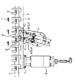
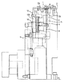
本発明のワーク搬送装置の一実施形態の構造を図2乃至図4に示す。図2は、ワーク搬送装置を正面から見た正面図、図3は側面図、図4は説明図である。図で1は搬送されるワーク、2はワーク1を収納する溝2aが上面に形成されたレールである。但し、図2ではレールは、後述する開口の位置での断面図として表されている。溝2a内に配置されたワーク1は、図2に示す図で、右から左の方向に搬送される。また、溝2aの底面には、レール2の裏側に貫通する長尺状の開口2bが形成されている。3はワーク1の後端部に当接してワーク1を搬送方向に押す平面視略L字状の基準爪、4はワークの前方に配置され、基準爪3と対となってワーク1の位置決めを行う平面視略L字状のクランプ爪、5はレール1と略平行に配置され、基準爪3を搬送方向または搬送方向と垂直な方向に移動させる長尺状の基準爪支持部材、6はレールと略平行に配置され、クランプ爪4を搬送方向または搬送方向と垂直な方向に移動させる長尺状のクランプ爪支持部材である。7は、基準爪支持部材5と、クランプ爪支持部材6とを、それぞれ別個に、レール1と略平行な方向に直線移動可能に支持する平軸受け部、8は平軸受け部7をレール1に略垂直な方向に往復運動させるシリンダ軸を備えた横方向駆動装置(横方向駆動手段)である。
【0009】
まず、ワーク1を挟む搬送爪について説明する。基準爪支持部材5には複数の基準爪3が固定されており、基準爪3は等間隔に配置されている。同様に、クランプ爪支持部材6には複数のクランプ爪4が固定され、クランプ爪4は、基準爪3のピッチと同じピッチで等間隔に配置されている。基準爪支持部材5及びクランプ爪支持部材6は、平軸受け部7によって支持されており、平軸受け部7に対する、レール1と略平行な方向への相対的な移動は可能に構成されているが、平軸受け部7に対する、レール1に略垂直な方向への相対的な移動は制限されている。これにより、一対となる基準爪3とクランプ爪4は、レール1と略平行な方向へ相対的に移動可能となり、ワーク1を挟んだり放したりすることが可能となる。また、平軸受け部7の、レール1に略垂直な方向への移動によって、一対となる基準爪3とクランプ爪4も、レール1に略垂直な方向に一緒に移動する。
【0010】
平軸受け部7がレール1に近づくことによって、基準爪3とクランプ爪4が、レール2の下方から、溝2aの底面に形成された開口2b内に侵入してワーク1を挟む位置に移動する。この状態で、基準爪支持部材5及びクランプ爪支持部材6を搬送方向に移動させれば、ワーク1をレール2に沿って搬送することができる。一方、平軸受け部7がレール1から遠ざかった位置では、基準爪3とクランプ爪4が、レール2の下方に移動するので、ワーク1を挟む状態が解除された状態となる。ワーク1を搬送した後は、この状態に移行させ、基準爪支持部材5及びクランプ爪支持部材6を搬送方向とは逆の方向に移動させることによって、次のワーク1を挟む位置に戻すことができる。
【0011】
次に、ワーク1を搬送方向に移動させ、かつ、その移動に合わせて搬送爪を開閉する構造について説明する。本発明のワーク搬送装置は、1個のレバーの回動往復運動によって、基準爪支持部材5及びクランプ爪支持部材6を搬送方向に移動させると共に、基準爪支持部材5とクランプ爪支持部材6の距離が変わるように構成したことを特徴とするものである。
【0012】
9が回動往復運動するレバーで、図2に示す例では、レール2の下方に配置されている。レバー9は、下方側にレール2に対して略垂直な方向の回転軸を備えており、レバー9の先端側には、回転軸の中心から119.21mm離れた位置に略円柱状の第1カムフォロア10が設けられている。また、その第1カムフォロア10よりは回転軸の中心に近い位置には第2カムフォロア11が設けられている。第2カムフォロア11は回転軸の中心から115.41mm離れた位置に設けられており、第1カムフォロア10と第2カムフォロア11は、回転軸の中心からレバー9の先端方向に向かう方向(腕方向)の中心線から18mm離れた位置に設けられている。つまり、第1カムフォロア10と第2カムフォロア11は、腕方向と垂直な方向には36mm離れている。また、第1カムフォロア10と第2カムフォロア11は、レバー9の回転軸と平行な回転軸を有しており、以上に説明したレバー9の先端側の位置で回動可能に構成されている。
【0013】
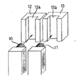
次に、レバー9と、基準爪支持部材5及びクランプ爪支持部材6とをつなぐ構造について説明する。図4に示す12は、第1カムフォロア10を収容する溝12aが形成された略直方体状の基準爪用カムで、基準爪支持部材5に固定されている。溝12aは、レール2に垂直な方向に延設され、溝12aの幅は、第1カムフォロア10の直径寸法にクリアランスを考慮した寸法に設定されている。レバー9が回転すると第1カムフォロア10は円弧状の軌跡を描くように移動する。第1カムフォロア10は、溝12aに沿って上下方向には移動可能に構成されているが、レール2と平行な方向の運動は溝12aの側壁によって制限されているので、レバー9が回転すると、第1カムフォロア10が溝12aの側壁を押して、基準爪支持部材5をレール2と略平行な方向に直線運動させることになる。
【0014】
同様に、クランプ爪支持部材6には、基準爪用カム12と同様のクランプ爪用カム13が固定されており、第2カムフォロア11を収容する溝13aが形成されており、レバー9が回転すると、第2カムフォロア11が溝13aの側壁を押して、クランプ爪支持部材6をレール2と略平行な方向に直線運動させる。
【0015】
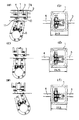
以上に説明しいたように構成されたワーク搬送装置の動作を図1に基づいて説明する。図1で、(a),(c),(e)は正面図、(b),(d),(f)はワークと搬送爪との位置関係を示す上面図である。また、(a),(b)はレバー9の先端部が、最も搬送方向とは反対の方向に移動した状態を示し、(c),(d)はレバー9の腕が鉛直方向を向いた状態を示し、(e),(f)はレバー9が最も搬送方向に移動した状態を示している。
【0016】
まず、(a)に示すように、レバー9の先端部を、最も搬送方向とは反対の方向に移動させる。この状態で、基準爪3とクランプ爪4の間隔は24.5mmとなり、ワーク1とのクリアランスは十分取れている状態となる。そして、横方向駆動装置8を駆動して平軸受け部7をレール1に近づけ、基準爪3とクランプ爪4が、レール2の下方から、溝2aの底面に形成された開口2b内に侵入してワーク1を挟む位置に移動させる。この場合、それらの爪とワーク1との間にはそれぞれ1mm程度のすきまが形成された状態となっている。この状態から、レバー9の先端部が搬送方向に移動する方向にレバー9を回転させる。これによって、基準爪3とクランプ爪4が搬送方向に移動し基準爪3がワーク1の後端部に当接して搬送方向に押す。
【0017】
レバー9の腕が鉛直方向を向いた、(c),(d)に示す状態では、基準爪3とクランプ爪4の間隔は24.75mmとなり一旦開いた状態となる。さらに、レバー9を回転させると、レバー9が最も搬送方向に移動した、(e),(f)に示す状態となる。この時、基準爪3とクランプ爪4の間隔は22.5mmとなり、最も爪が閉じた状態となってワーク1の搬送及び位置決めが完了する。
【0018】
(e),(f)に示した状態で、横方向駆動装置8を駆動して平軸受け部7をレール1から遠ざけ、基準爪3とクランプ爪4によってワーク1を挟んだ状態を解除し、その状態で、レバー9を(a)に示す位置に戻して次のワーク1の搬送に移る。
【0019】
【発明の効果】
請求項1記載のワーク搬送装置によれば、搬送爪によってワークに傷が付くという問題点を解決でき、簡単な機構で生産性の向上を図ることができる。
【図面の簡単な説明】
【図1】本発明のワーク搬送装置の動作を示す説明図で、ある。端子位置検出方法に用いる端子位置検出装置の一実施形態を示す図で、(a),(c),(e)は正面図、(b),(d),(f)はワークと搬送爪との位置関係を示す上面図である。
【図2】本発明のワーク搬送装置の一実施形態を示す平面図である。
【図3】本発明のワーク搬送装置の一実施形態を示す側面図である。
【図4】本発明のワーク搬送装置の一実施形態を示す説明図である。
【符号の説明】
1 ワーク
2 レール
3 基準爪
4 クランプ爪
5 基準爪支持部材
6 クランプ爪支持部材
8 横方向駆動装置(横方向駆動手段)
9 レバー
10 第1カムフォロア
11 第2カムフォロア
12 基準爪用カム
13 クランプ爪用カム[0001]
BACKGROUND OF THE INVENTION
The present invention relates to a work transfer device used in a production apparatus that transfers a work in one direction within a rail and performs assembly and the like.
[0002]
[Prior art]
2. Description of the Related Art Conventionally, in a production apparatus that accommodates a workpiece in a groove provided on a rail and conveys the workpiece in one direction for assembling or the like, for example, a workpiece conveyance device including a plurality of a pair of conveyance claws that convey the workpiece in between. In such a workpiece conveying device, for example, the conveying claws are arranged on the side of the rail, and a pair of conveying claws spaced apart by a predetermined distance move in a direction approaching the rail to sandwich the workpiece in the rail, and in this state After the transport claw has moved in the transport direction, the transport claw is moved away from the rail to release the state of pinching the workpiece, and the transport claw is in the direction opposite to the transport direction at the position where the transport claw has moved away from the rail. It is configured to return and transport the next workpiece. Usually, the distance between the pair of conveyance claws is set to a value obtained by adding, for example, a clearance within the positioning accuracy of the workpiece after conveyance to the length of the workpiece in the rail direction where the conveyance claw contacts. The distance between the transport claws was fixed at that value.
[0003]
However, when a workpiece is sandwiched between a pair of conveyance claws with a fixed distance between the claws, there is a problem that the conveyance claw hits the workpiece and scratches the workpiece due to insufficient adjustment of the distance between the conveyance claws or dimensional variation of the workpiece. It was. As one transport method to solve this problem, after fixing the distance between the pair of transport claws without securing the distance between the pair of transport claws, with sufficient clearance, Has a method (conveying claw opening / closing type) in which the distance between the pair of conveying claws is reduced so that the position after conveyance of the workpiece is within the positioning accuracy.
[0004]
[Problems to be solved by the invention]
However, in the conveyance claw opening / closing type work conveyance device, since the pair of conveyance claws need to be moved separately, the drive for moving one claw (reference claw) of the pair of conveyance claws, which serves as a reference for positioning the workpiece. Two drive devices were necessary, that is, a drive device that moves the device and the other claw (clamp claw) of the pair of transport claws.
[0005]
In addition, there is a problem that the mechanism is complicated when the reference claw is cam-fed and the clamp claw is moved using the cam. Also, the reference claw is cam-fed and the clamp claw is a cylinder mechanism or a pulse motor. However, there is a problem in that the method of moving with the method cannot cope with the high speed of the production apparatus.
[0006]
The present invention has been invented in order to solve the above-mentioned problems, and an object of the present invention is to provide a structure of a transport claw opening / closing type work transport apparatus that has a simple mechanism and can improve productivity. There is.
[0007]
[Means for Solving the Problems]
The workpiece transfer apparatus according to
A reference claw that contacts the rear end of the work and pushes the work in the transport direction; a clamp claw that is disposed in front of the work and that pairs the reference claw to position the work; and the rail A long reference claw support member that is arranged substantially parallel and moves the reference claw in a conveyance direction or a direction perpendicular to the conveyance direction, and is arranged substantially parallel to the rail, and the clamp claw is arranged in the conveyance direction or conveyance direction. A long clamp claw support member that moves in a direction perpendicular to the axis, a lever that rotates and reciprocates at a predetermined angle around a rotation axis provided on the rear end side, and a position on the front end side of the lever The first cam follower, the second cam follower disposed closer to the rotation shaft than the first cam follower, and the reference claw support fixed to the reference claw support member and subjected to the reciprocating movement of the lever. A reference claw cam for reciprocating the material in a direction substantially parallel to the rail, and a clamp claw support member fixed to the clamp claw support member and subjected to a reciprocating motion of the lever, the clamp claw support member being substantially parallel to the rail. A clamp claw cam that reciprocates in a direction, and a lateral drive means that reciprocates the reference claw support member and the clamp claw support member in a direction substantially perpendicular to the rail,
The distance between the reference claw and the clamp claw that sandwiches the work is reduced and the work is positioned with the tip of the lever moved most in the transport direction.
[0008]
DETAILED DESCRIPTION OF THE INVENTION
The structure of an embodiment of the workpiece transfer apparatus of the present invention is shown in FIGS. 2 is a front view of the workpiece transfer device as viewed from the front, FIG. 3 is a side view, and FIG. 4 is an explanatory view. In the figure,
[0009]
First, the conveyance nail which pinches | interposes the workpiece |
[0010]
As the flat bearing portion 7 approaches the
[0011]
Next, a structure for moving the
[0012]
Reference numeral 9 denotes a lever that rotates and reciprocates, and is disposed below the rail 2 in the example shown in FIG. The lever 9 is provided with a rotating shaft in a direction substantially perpendicular to the rail 2 on the lower side, and the first end of the lever 9 has a substantially cylindrical first at a position 119.21 mm away from the center of the rotating shaft. A
[0013]
Next, a structure for connecting the lever 9 to the reference
[0014]
Similarly, a
[0015]
The operation of the workpiece transfer apparatus configured as described above will be described with reference to FIG. 1, (a), (c), and (e) are front views, and (b), (d), and (f) are top views showing the positional relationship between the workpiece and the conveyance claw. (A) and (b) show the state where the tip of the lever 9 has moved in the direction most opposite to the conveying direction, and (c) and (d) show the arm of the lever 9 facing the vertical direction. (E), (f) shows a state in which the lever 9 has moved most in the transport direction.
[0016]
First, as shown to (a), the front-end | tip part of the lever 9 is moved to the direction opposite to the conveyance direction most. In this state, the distance between the
[0017]
In the state shown in (c) and (d) in which the arm of the lever 9 is oriented in the vertical direction, the distance between the
[0018]
In the state shown in (e) and (f), the lateral drive device 8 is driven to move the flat bearing portion 7 away from the
[0019]
【The invention's effect】
According to the workpiece transfer device of the first aspect, the problem that the workpiece is scratched by the transfer claw can be solved, and the productivity can be improved with a simple mechanism.
[Brief description of the drawings]
FIG. 1 is an explanatory diagram showing the operation of a workpiece transfer apparatus according to the present invention. It is a figure which shows one Embodiment of the terminal position detection apparatus used for a terminal position detection method, (a), (c), (e) is a front view, (b), (d), (f) is a workpiece | work and a conveyance nail | claw FIG.
FIG. 2 is a plan view showing an embodiment of the work transfer device of the present invention.
FIG. 3 is a side view showing an embodiment of the work transfer device of the present invention.
FIG. 4 is an explanatory view showing an embodiment of the work transfer device of the present invention.
[Explanation of symbols]
1 Work 2
9
Claims (1)
前記ワークの後端部に当接して前記ワークを搬送方向に押す基準爪と、前記ワークの前方に配置され、前記基準爪と対となって前記ワークの位置決めを行うクランプ爪と、前記レールと略平行に配置され、前記基準爪を搬送方向または搬送方向と垂直な方向に移動させる長尺状の基準爪支持部材と、前記レールと略平行に配置され、前記クランプ爪を搬送方向または搬送方向と垂直な方向に移動させる長尺状のクランプ爪支持部材と、後端側に設けられた回転軸を中心に所定角度の回動往復運動を行うレバーと、前記レバーの先端側の位置に配置された第1カムフォロアと、その第1カムフォロアよりは回転軸に近い位置に配置された第2カムフォロアと、前記基準爪支持部材に固定されて前記レバーの回動往復運動をうけて前記基準爪支持部材を前記レールと略平行な方向に往復運動させる基準爪用カムと、前記クランプ爪支持部材に固定されて前記レバーの回動往復運動をうけて前記クランプ爪支持部材を前記レールと略平行な方向に往復運動させるクランプ爪用カムと、前記基準爪支持部材及びクランプ爪支持部材を前記レールと略垂直な方向に往復運動させる横方向駆動手段とを備え、
前記レバーの先端が最も搬送方向に移動した状態で、前記ワークを挟む、前記基準爪と前記クランプ爪との距離が小さくなり前記ワークの位置決めが行われることを特徴とするワーク搬送装置。A workpiece transfer device used in a production device that transfers a workpiece in one direction in a rail and performs assembly, etc.
A reference claw that contacts the rear end of the work and pushes the work in the transport direction; a clamp claw that is disposed in front of the work and that pairs the reference claw to position the work; and the rail A long reference claw support member that is arranged substantially parallel and moves the reference claw in a conveyance direction or a direction perpendicular to the conveyance direction, and is arranged substantially parallel to the rail, and the clamp claw is arranged in the conveyance direction or conveyance direction. A long clamp claw support member that moves in a direction perpendicular to the axis, a lever that rotates and reciprocates at a predetermined angle around a rotation axis provided on the rear end side, and a position on the front end side of the lever The first cam follower, the second cam follower disposed closer to the rotation shaft than the first cam follower, and the reference claw support fixed to the reference claw support member and subjected to the reciprocating movement of the lever. A reference claw cam for reciprocating the material in a direction substantially parallel to the rail, and a clamp claw support member fixed to the clamp claw support member and subjected to a reciprocating motion of the lever, the clamp claw support member being substantially parallel to the rail. A clamp claw cam that reciprocates in a direction, and a lateral drive means that reciprocates the reference claw support member and the clamp claw support member in a direction substantially perpendicular to the rail,
A workpiece transfer apparatus, wherein the distance between the reference claw and the clamp claw that sandwiches the workpiece is reduced and the workpiece is positioned with the tip of the lever moved most in the transfer direction.
Priority Applications (1)
| Application Number | Priority Date | Filing Date | Title |
|---|---|---|---|
| JP33882899A JP3772615B2 (en) | 1999-11-29 | 1999-11-29 | Work transfer device |
Applications Claiming Priority (1)
| Application Number | Priority Date | Filing Date | Title |
|---|---|---|---|
| JP33882899A JP3772615B2 (en) | 1999-11-29 | 1999-11-29 | Work transfer device |
Publications (2)
| Publication Number | Publication Date |
|---|---|
| JP2001151327A JP2001151327A (en) | 2001-06-05 |
| JP3772615B2 true JP3772615B2 (en) | 2006-05-10 |
Family
ID=18321822
Family Applications (1)
| Application Number | Title | Priority Date | Filing Date |
|---|---|---|---|
| JP33882899A Expired - Fee Related JP3772615B2 (en) | 1999-11-29 | 1999-11-29 | Work transfer device |
Country Status (1)
| Country | Link |
|---|---|
| JP (1) | JP3772615B2 (en) |
Families Citing this family (1)
| Publication number | Priority date | Publication date | Assignee | Title |
|---|---|---|---|---|
| CN110170836B (en) * | 2019-06-25 | 2024-02-27 | 宁夏机械研究院股份有限公司 | Double-station workpiece grabbing device |
-
1999
- 1999-11-29 JP JP33882899A patent/JP3772615B2/en not_active Expired - Fee Related
Also Published As
| Publication number | Publication date |
|---|---|
| JP2001151327A (en) | 2001-06-05 |
Similar Documents
| Publication | Publication Date | Title |
|---|---|---|
| US5636963A (en) | Method of handling wafers in a vacuum processing apparatus | |
| US5697752A (en) | Overhead transfer clamp actuator and linkage | |
| JPS61119868A (en) | Cam device for material feeding mechanism | |
| US20020197722A1 (en) | Apparatus and process for transporting sample plates | |
| JP3772615B2 (en) | Work transfer device | |
| KR102107780B1 (en) | Wafer aligning apparatus and method | |
| JPH11284059A (en) | Semiconductor wafer holding device | |
| JP3244047B2 (en) | Parts transfer device | |
| JP4807654B2 (en) | Article conveying manipulator and article conveying method | |
| JPH06278857A (en) | Transport device | |
| JPH09153534A (en) | Wafer transfer device | |
| JPH028579Y2 (en) | ||
| JPH04201131A (en) | Inclinination device for work on conveyance line for work | |
| JPH02229499A (en) | Substrate transfer device | |
| JP4687120B2 (en) | Article alignment device | |
| JPH0539791Y2 (en) | ||
| JPH0265952A (en) | Workpiece posture conversion device | |
| JPH0218072Y2 (en) | ||
| KR200176968Y1 (en) | Lead frame reversing device | |
| JP3375124B2 (en) | Lead frame delivery mechanism | |
| JPH0248214Y2 (en) | ||
| JPH02208180A (en) | Door mounting device for automobile | |
| JP2001157930A (en) | Work carrying apparatus | |
| JPH08323592A (en) | Transfer device | |
| JPS6221397Y2 (en) |
Legal Events
| Date | Code | Title | Description |
|---|---|---|---|
| TRDD | Decision of grant or rejection written | ||
| A01 | Written decision to grant a patent or to grant a registration (utility model) |
Free format text: JAPANESE INTERMEDIATE CODE: A01 Effective date: 20060124 |
|
| A61 | First payment of annual fees (during grant procedure) |
Free format text: JAPANESE INTERMEDIATE CODE: A61 Effective date: 20060206 |
|
| FPAY | Renewal fee payment (event date is renewal date of database) |
Free format text: PAYMENT UNTIL: 20090224 Year of fee payment: 3 |
|
| S533 | Written request for registration of change of name |
Free format text: JAPANESE INTERMEDIATE CODE: R313533 |
|
| FPAY | Renewal fee payment (event date is renewal date of database) |
Free format text: PAYMENT UNTIL: 20090224 Year of fee payment: 3 |
|
| R350 | Written notification of registration of transfer |
Free format text: JAPANESE INTERMEDIATE CODE: R350 |
|
| FPAY | Renewal fee payment (event date is renewal date of database) |
Free format text: PAYMENT UNTIL: 20100224 Year of fee payment: 4 |
|
| FPAY | Renewal fee payment (event date is renewal date of database) |
Free format text: PAYMENT UNTIL: 20100224 Year of fee payment: 4 |
|
| FPAY | Renewal fee payment (event date is renewal date of database) |
Free format text: PAYMENT UNTIL: 20110224 Year of fee payment: 5 |
|
| FPAY | Renewal fee payment (event date is renewal date of database) |
Free format text: PAYMENT UNTIL: 20120224 Year of fee payment: 6 |
|
| FPAY | Renewal fee payment (event date is renewal date of database) |
Free format text: PAYMENT UNTIL: 20130224 Year of fee payment: 7 |
|
| FPAY | Renewal fee payment (event date is renewal date of database) |
Free format text: PAYMENT UNTIL: 20130224 Year of fee payment: 7 |
|
| FPAY | Renewal fee payment (event date is renewal date of database) |
Free format text: PAYMENT UNTIL: 20140224 Year of fee payment: 8 |
|
| LAPS | Cancellation because of no payment of annual fees |