JP3772253B2 - Fastener - Google Patents
Fastener Download PDFInfo
- Publication number
- JP3772253B2 JP3772253B2 JP2000119643A JP2000119643A JP3772253B2 JP 3772253 B2 JP3772253 B2 JP 3772253B2 JP 2000119643 A JP2000119643 A JP 2000119643A JP 2000119643 A JP2000119643 A JP 2000119643A JP 3772253 B2 JP3772253 B2 JP 3772253B2
- Authority
- JP
- Japan
- Prior art keywords
- elastic locking
- hole
- locking legs
- base
- engaged
- Prior art date
- Legal status (The legal status is an assumption and is not a legal conclusion. Google has not performed a legal analysis and makes no representation as to the accuracy of the status listed.)
- Expired - Fee Related
Links
Images


Landscapes
- Clamps And Clips (AREA)
- Insertion Pins And Rivets (AREA)
- Vehicle Interior And Exterior Ornaments, Soundproofing, And Insulation (AREA)
- Connection Of Plates (AREA)
Description
【0001】
【発明の属する技術分野】
この発明に係る止着具は、例えば、車両用サンバイザに付設の軸部を保持するホルダの基部に設けられ、このホルダを車両の天井部に止着するのに利用する等、各種物品を壁面に形成された透孔に止着自在とする止着具に関する。
【0002】
【従来の技術】
自動車室内の運転席等の前方上部近傍には、太陽光等の光から乗員の目を保護し、安全な走行を確保すべく、従来からサンバイザが設置されている。すなわち、車両前方のフロントガラスから差し込んでくる光を遮るために、上記サンバイザを設けている。このようなサンバイザは、図19及び図20に示すように、車両Cの運転席22等の前方上部の天井部23に、枢軸24により回動自在に設けられている。この枢軸24は一対の支持部材25により上記天井部23に固設している。上記光を遮る場合には、サンバイザ1を図示の状態に回動させる。曇天等のためにサンバイザ1を使用しない場合には、天井部23に向けて回動させ、格納状態とする。尚、上記サンバイザ1には短い軸部26を設けており、サンバイザ1の不使用時(格納状態時)には、この軸部26を別途設けたホルダ27に保持し、サンバイザ1が不用意に回動しないようにしている。
【0003】
ところで、上記ホルダ27を上記天井部23に固設する場合、従来は、ビスによってねじ止めすることで行なっていた。しかしながら、このようなねじ止めによる固定は、取り付け後の見栄えが悪く、又、ビスによって天井部23を疵付ける虞もある。そこで、上記ねじ止めに代えて、上記ホルダ27に係止爪を設け、この係止爪を上記天井部23に形成した透孔に係止させる構造のものが考えられている。例えば、特開平4−110224号公報には、ホルダ27を構成する基部に、位置決め挿入部材と一対の係止爪とを設けた発明が記載されている。上記公報記載の技術によれば、車両Cの天井部23に形成した透孔に、上記位置決め挿入部材と係止爪とを挿通することにより、上記ホルダ27を天井部23に確実に取り付けることができる。これとともに、取り付け後の見栄えが悪くなることが防止され、しかも天井部23に疵を付ける虞がなくなる。
【0004】
【発明が解決しようとする課題】
ところが、上記公報記載の発明においては、以下のような不都合が存在する。すなわち、天井部23にホルダ27を取り付ける場合、上記係止爪を弾性変形させて透孔の内側(天井部23の内側)に挿入する。挿入後は係止爪が復帰することにより天井部23内側に係止してこのホルダ27を保持する。このため、取り付け時に、上記係止爪を弾性変形させるために或る程度の力を要する一方で、取り付け後の保持力に不安が残る。すなわち、このホルダ27は、自由状態における一対の係止爪が天井部23に設けた透孔の周縁部に係合することにより支持されているため、サンバイザ1の軸部26を保持することに伴う加重に、長期に亙って耐え得ることができない虞がある。その一方で、修理等の場合に、上記ホルダ27を天井部23から取り外すことは容易ではない。何となれば、天井部23の内側(車両室外側)に位置する係止爪を、天井部23の外側(車両室内側)から弾性変形させることはきわめて困難であるからである。このため、上記一対の係止爪を上記透孔から抜き出すことは容易でなく、この結果、取り付け後のホルダ27の取り外しは容易ではない。
【0005】
この発明に係る止着具は、上述したような事情に鑑みて創案されたもので、取り付けるべき壁面に対し、軽い力で容易且つ確実に取り付けでき、しかも、必要に応じて容易に取り外し可能な止着具を提供することを目的としている。
【0006】
【課題を解決するための手段】
この発明に係る止着具は、請求項1に記載したように、車両用ルーフライニングに形成された透孔に、上記車両用ルーフライニングの一面側から止着自在な止着具であって、基部と、この基部の一側面にその一端を、上記基部の他側面にその他端を、それぞれ開口させた通孔と、上記基部の一側面で上記通孔の互いに対向する縁部からそれぞれ延出し、上記透孔の互いに対向する縁部にそれぞれ係合する、互いに平行な一対の第一の弾性係止脚と、上記第一の弾性係止脚と並んで上記基部の一側面から延出し、上記車両用ルーフライニングの他面側において上記第一の弾性係止脚におけるよりも大きく上記透孔の外方に向けて張り出すように形成され、上記縁部にそれぞれ係合する、互いにハ字状に設けられた一対の第二の弾性係止脚と、上記基部の一側面に形成され上記透孔の縁部のうち上記一対の第二の弾性係止脚が係合する縁部と交叉する方向の縁部に当接するストッパ壁と、上記基部の一端部に連続して回動自在に設けられ、回動によって上記通孔内に挿入自在で、挿入に伴って上記第一、第二の各弾性係止脚のうちの少なくとも第一の弾性係止脚を上記透孔の周縁部に係合させる向きに押圧する挿入部材と、を備え、上記一対の第二の弾性係止脚の係止片は上記透孔の隅部近傍に、夫々が外方に向かう状態で係合することを特徴とするものである。
【0007】
上述のように構成される請求項1に記載した止着具を、上記車両用ルーフライニングに設けた透孔を介してこの車両用ルーフライニングに取り付ける際の作用は、次のとおりである。すなわち、上記各一対ずつ設けた第一、第二の各弾性係止脚を弾性変形させつつ上記透孔内に挿入する。この状態においては、第一の弾性係止脚が上記透孔の縁部に軽く係合するとともに、第二の弾性係止脚が上記透孔の縁部に係合する(仮固定状態)。この仮固定状態においては、止着具を4箇所位置で係合させているため、この止着具を仮固定した状態の車両用ルーフライニングを例に搬送等したとしても止着具が不用意に離脱することはない。この結果、製造コスト削減等の観点から推進されている、所謂モジュール化を図ることができる。すなわち、上記車両用ルーフライニングに上記止着具を仮固定した状態で、この車両用ルーフライニングを他の場所に搬送し、当該他の場所でこの車両用ルーフライニングを他の部材等に組み付け、更に上記止着具を次述するように本固定することが可能になる。尚、この発明においては、上記基部にストッパ壁を設けたため、第二の弾性係止脚は、型構造等の製造要件によりストッパ壁と一定距離を離間させて設けなければならず、透孔隅部から遠ざかり強度が小さい透孔中央寄りに係合することになるのを、本発明では、第二の弾性係止脚を上記透孔の強度が大きい隅部近傍に、夫々が外方に向かう状態で係合するようにハ字状に形成したため、該第二の弾性係止脚の係合力を保持することができる。
【0008】
更に、この仮固定状態から本固定状態とするには、上記挿入部材を上記通孔に向けて回動させ、この通孔内に挿入する。これにより、上記基部の一側面で上記通孔の互いに対向する縁部から延出する一対の第一の弾性係止脚は、それぞれ対向する透孔の縁部により強く係合する向きに押圧されるため、上記第一の弾性係止脚はそれぞれの縁部に強固に係合する。この結果、第一、第二の各弾性係止脚が上記透孔の周縁部の4箇所位置で係合する。特に、第一の弾性係止脚は、上記挿入部材の挿入に伴って強固に係合するため、取り付け後に容易に脱落することがなくなる(本固定状態)。
【0009】
しかも、上記挿入部材を設けたことに伴い、上記第一の弾性係止脚の自由状態における形状を、係合代を大きくすべく反った状態としておく必要がなく、上記通孔の縁部から直上に立設できるため、上記壁面に軽い力で容易に取り付け可能となる。又、上記本固定状態から止着具を取り外したい場合には、先ず、上記挿入部材を上記通孔から抜き出す。これにより、上記第一の弾性係止脚は自由状態に復帰し、上記透孔の縁部に軽く係合する状態となる。次いで、上記基部の一側の第一、第二の弾性係止脚の基端部を支点として、上記基部の他側を上記一側に向けて回動させる。これにより、上記他側の第一、第二の各弾性係止脚が弾性変形しつつ上記透孔内から抜け出る。他側の第一、第二の各弾性係止脚が上記透孔内から抜け出た後は、上記一側の第一、第二の各弾性係止脚は、上記透孔内から容易に抜け出る。従って、止着した状態から取り外すことも、容易に行なえる。
【0010】
尚、上述の構成に加え、上記透孔の縁部のうち、上記一対の第二の弾性係止脚が係合する縁部と交叉する方向の縁部に当接するストッパ壁を、上記基部の一側面に設けた構成を採用したので、取り付け後の止着具が、上記一対の第二の弾性係止脚が係合する縁部と交叉する方向にずれ動くことが防止され、止着具の確実な固定を維持できる。
【0011】
また、請求項2に記載の発明にあっては、前記一対の第二の弾性係止脚を、前記一対の第一の弾性係止脚の剛性よりも小さく形成したので、ラップ量が大きく、剛性が高い部位に係合できる第二の弾性係止脚の剛性を小さくすることができるため、車両用ルーフライニングに容易に取り付けることができ、かつ、取り付け後は強固に係合でき、また、取り外しも容易である。さらに、請求項3に記載の発明にあっては、前記挿入部材の先端部に、前記一対の第一の弾性係止脚の先端にそれぞれ係合する係合突起が、対応する第一の弾性係止脚の上端部の互いに整合しない位置に係合するように、形成位置をずらせて設けたので、一方の係合突起が係合した後、他方の係合突起を係合させることができ、係合作業時に要する力が小さくて済み、作業性が向上する、という効果を得ることができる。
【0012】
さらに、この発明にあっては、請求項4に記載したように、車両用ルーフライニングに形成された透孔に、上記車両用ルーフライニングの一面側から止着自在な止着具であって、基部と、この基部の一側面にその一端を、上記基部の他側面にその他端を、それぞれ開口させた通孔と、上記基部の一側面で上記通孔の互いに対向する縁部からそれぞれ延出し、上記透孔の互いに対向する縁部にそれぞれ係合する、互いに平行な一対の第一の弾性係止脚と、上記第一の弾性係止脚と並んで上記基部の一側面から延出し、上記車両用ルーフライニングの他面側において上記第一の弾性係止脚におけるよりも大きく上記透孔の外方に向けて張り出すように形成され、上記縁部にそれぞれ係合する、互いにハ字状に設けられた一対の第二の弾性係止脚と、上記基部の一端部に連続して回動自在に設けられ、回動によって上記通孔内に挿入自在で、挿入に伴って上記第一、第二の各弾性係止脚を上記透孔の周縁部に係合させる向きに押圧する挿入部材と、を備え、上記一対の第二の弾性係止脚の係止片は上記透孔の隅部近傍に、夫々が外方に向かう状態で係合するように構成したので、挿入部材の挿入時には上記第一の弾性係止脚とともに上記第二の弾性係止脚をも押圧することができ、上記第一、第二の両弾性係止脚を透孔の縁部に強固に係合させることができ、止着の本固定状態を、より強固なものとすることができ、且つ、その際、第二の弾性係止脚に挿入部材を確実に押圧させるために、第二の弾性係止脚を挿入部材寄りに配置し、その結果、強度が小さい透孔中央寄りに係合する場合であっても、第二の弾性係止脚を上記透孔の強度が大きい隅部近傍に、夫々が外方に向かう状態で係合するようにハ字状に形成したため、該第二の弾性係止脚の係合力を保持することができる。
【0013】
【発明の実施の形態】
以下、添付図面に示す発明の実施の形態例に基づき、この発明を詳細に説明する。
【0014】
図1乃至図10は、この発明の実施の第1形態例に係る止着具を示しており、本形態例に係る止着具は、前述したサンバイザ1の軸部26(図20参照)を保持するためのホルダ3に適用したもので、車両Cの天井部23(図20参照)を構成するルーフライニング6に形成した長矩形の透孔7に、上記ホルダ3を取り付けるために利用する。上記ルーフライニング6が特許請求の範囲に記載した壁面に相当する。上記ホルダ3は合成樹脂部材により構成されており、基部8と、通孔9と、それぞれ一対ずつ設けられた第一、第二の各弾性係止脚10、11と、挿入部材12と、を備えている。
【0015】
上記基部8の一面側(図1乃至図4のそれぞれ下面側、図5(A)の裏面側、図5(C)(D)及び図6(A)のそれぞれ下面側)には、上記サンバイザ1の軸部26を保持するためのフック13を形成している。
【0016】
上記通孔9は長矩形状で、上記基部8の中央部に、この基部8の一側面にその一端を、この基部8の他側面にその他端を、それぞれ開口させた状態で形成している。
【0017】
上記一対の第一の弾性係止脚10、10は、上記基部8の一側面で上記通孔9の互いに対向する縁部9a、9aからそれぞれ直上に向けて延出させている。この一対の弾性係止脚10、10は、図8に示すように、上記透孔7の互いに対向する縁部7a、7aにそれぞれ係合自在である。すなわち、上記第一の弾性係止脚10、10の互いに対向しない側面上半部には、図1乃至図4に示すように、傾斜突部10a、10aを形成している。この傾斜突部10a、10aの下面が上記縁部7a、7aに係合する。又、この傾斜突部10a、10aの傾斜面は、下方に向かうに従って厚肉となるように傾斜させている。これにより、この第一の弾性係止脚10、10の透孔7内への挿入及び透孔7からの離脱を容易にしている。又、上記傾斜突部10a、10aの存在により、透孔7への挿入時に節度感(クリック感)を得られる。
【0018】
上記一対の第二の弾性係止脚11、11は、上記基部8の一側面から延出させており、柱部14と、この柱部14の上半部に設けられ、上記透孔7の外方に向けて延びる略三角形状の係止片15と、を有している。各第二の弾性係止脚11、11の係止片15、15同士は、図1、図2、図5(A)(B)(C)、図6(A)にそれぞれ示すように、互いにハ字状となるように形成している。そして、上記ルーフライニング6の他面側(図3、図4、図6(A)(B)の上面側)で上記透孔7の互いに対向する縁部7a、7aにそれぞれ係合自在である。このように、係止片15はルーフライニング6と言った軟質材に固定されるものであるため、所謂ラップ量を多くしている。
【0019】
尚、本形態例の場合、上記係止片15、15の下面は、先端に向かうに従って上方に向かう形状としている。これは、この係止片15、15の下面に当接する縁部7a、7aの不可避的な製造誤差等に基づく凹凸を吸収するとともに、ホルダ3を上記ルーフライニング6から取り外す際に、この第二の弾性係止脚11、11が容易に透孔7から抜け出るようにするためである。又、本形態例においては、この係止片15、15の突出量Δ1を、上記第一の弾性係止脚10、10の傾斜突部10a、10aの突出量Δ2よりも大きく(Δ1>Δ2)している。更に、上記第一の弾性係止脚10、10の剛性が大きく、上記第二の弾性係止脚11、11の剛性が上記第一の弾性係止脚10、10よりも小さくなる(柔軟になる)ように構成している。このための手段としては、例えば、第一の弾性係止脚10、10の厚さ寸法を第二の弾性係止脚11、11に比較して大きくする等、従来から知られた手段を用いることができる。上述のように、上記第一の弾性係止脚10、10の剛性を上記第二の弾性係止脚11、11の剛性よりも大きくする(逆に言えば、上記第二の弾性係止脚11、11を上記第一の弾性係止脚10、10よりも柔軟に構成する)とともに、各突出量Δ1、Δ2をΔ1>Δ2となるように構成するのは、以下の理由による。すなわち、ホルダ3を天井部23に対して容易に取り付けできるとともに、取り付け後はこのホルダ3が上記天井部23に強固に係合する一方で、ホルダ3を天井部23から取り外したい場合には容易に取り外しを行なえるようにするためである。
【0020】
上記挿入部材12は、基部8の一端部(図1乃至図4のそれぞれ右端部、図5(A)の右端部)に、この基部8の他側面(図1乃至図4のそれぞれ上面側、図5(A)の表面側)に向かう回動自在に連結された回動板部19の一側面(図2、図3の左側面)に立設されている。上記基部8の一端部と回動板部19との連結部19aは、その肉厚を小さくすることにより、一種の連結部材として機能させ、この連結部19aを軸として上記挿入部材12を回動自在としている。上記挿入部材12を回動させることにより、上記通孔9内に該挿入部材12が挿入し、上記一対の第一の弾性係止脚10、10の傾斜突部10a、10aが、それぞれ対応する透孔7の縁部7a、7aに強く係合する向き(傾斜突部10a、10a同士が互いに離隔する向き)に押圧する。この結果、第一の弾性係止脚10、10の傾斜突部10a、10aは、上記縁部7a、7aに強固に係合する。
【0021】
尚、本形態例の場合、上記挿入部材12の先端部に、この挿入部材12を上記通孔9に挿入した際に、上記一対の第一の弾性係止脚10、10の先端部にそれぞれ係合する係合突起16a、16bを設けている。これら係合突起16a、16bは、図7に示すように、対応する第一の弾性係止脚10、10の上端部の互いに整合しない位置に係合するよう、形成位置をずらせて設けている。このため、一対の係合突起16a、16bが同時に第一の弾性係止脚10、10には係合せず、一方の係合突起16aが係合した後、他方の係合突起16bが係合する。従って、この係合作業時(挿入部材12の挿入作業時)に要する力が小さくて済み、作業性が向上する。
【0022】
更に、本形態例の場合、上記透孔7の縁部のうち、上記一対の第二の弾性係止脚11、11の係止片15、15が係合する縁部7a、7aと交叉する(縁部7a、7a同士を結んでできる仮想的な線分に対して略直角な)方向の縁部7bに当接するストッパ壁17を、上記基部8の一側面に設けている。尚、図1乃至図4及び図5(A)(B)(C)に示すように、このストッパ壁17の中央部には、リブ17aを設け、このストッパ壁17の剛性を向上させている。このリブ17aを形成する位置は、上記第二の弾性係止脚11、11を構成する係止片15、15と干渉しない位置であることは言うまでもない。上記ストッパ壁17は、サンバイザ1を使用状態としたり格納状態とする際に発生する荷重を受け、ホルダ3が上記縁部7bに向けてずれ動くことを防止する。
【0023】
上述のように構成される本形態例に係るホルダ3を、上記透孔7を介してこのルーフライニング6に取り付ける際の作用は、次のとおりである。すなわち、上記各一対ずつ設けた第一、第二の各弾性係止脚10、11を弾性変形させつつ上記透孔7内に挿入する(図4に示す状態)。この状態においては、上記第一の弾性係止脚10、10を構成する傾斜突部10a、10bが透孔7の縁部7a、7aに軽く係合するとともに、上記第二の弾性係止脚11、11を構成する係止片15、15がやはり上記縁部7a、7aに係合する。又、上記ストッパ壁17が縁部7bに当接する。この状態が、ルーフライニング6にホルダ3を仮固定した状態である。ホルダ3は、それぞれ一対ずつの第一、第二の各弾性係止脚10、11によって合計4箇所位置で係合する。又、互いに当接するストッパ壁17と縁部7bとも、当該当接部分に作用する摩擦力により、このホルダ3のルーフライニング6への固定に寄与する。これらの結果、ホルダ3を仮固定した状態のルーフライニング6を仮に搬送等したとしても、ホルダ3は不用意に脱落することはない。近年、製造コスト削減等の観点から、所謂モジュール化が図られている。すなわち、上記天井部23を構成するルーフライニングやトリム等の内装部材に上記ホルダを仮固定しておき、この内装部材とともに車体パネルに本固定することが求められている。本形態例に係るホルダ3においては、上述したように、ルーフライニング6へ仮固定した状態において、十分な強度でこのルーフライニング6に固定されるため、上記モジュール化を推進することが可能になる。
【0024】
更に、上記ホルダ3をルーフライニング6に本固定する場合、第一、第二の各弾性係止脚10、11を透孔7内に完全に挿入した状態で、上記挿入部材12を上記通孔9に向けて回動させ、この通孔9内に挿入する。これにより、上記一対の第一の弾性係止脚10、10は、傾斜突部10a、10aが対応する縁部7a、7aに強く係合する向き(第一の弾性係止脚10、10同士の間隔が増大する向き)に押圧される。この結果、上記傾斜突部10a、10aが、それぞれ対応する縁部7a、7aに強固に係合する。又、挿入部材12の先端位置に設けた一対の係合突起16、16が上記第一の弾性係止脚10、10の先端部に係合する。これにより、挿入部材12が不意に通孔9から抜け出ることが防止されるとともに、挿入部材12の通孔9内への挿入完了時に、節度感(クリック感)を得られる。
【0025】
上述したように、第一、第二の各弾性係止脚10、11は、上記透孔7の縁部7a、7aの4箇所位置で係合する。特に、比較的剛性を大きくした第一の弾性係止脚10、10は、上記挿入部材12の挿入に伴って強固に係合する。更に、上記挿入部材12に設けた係合突起16a、16bが第一の弾性係止脚10、10の先端部に係合し、挿入部材12の通孔9からの抜け出しを防止する。これらの各係合が相俟って、ルーフライニング6に取り付けたホルダ3が、このルーフライニング6から容易に脱落することがなくなる。しかも、上記挿入部材12を設けたことに伴い、上記第一の弾性係止脚10、10の自由状態における形状を、縁部7a、7aとの係合代を大きくすべく、それぞれ対応する縁部7a、7aに向けて反った状態に形成する必要がなく、上記通孔9の縁部9a、9aから真直ぐ立設させておくことができる。このため、ホルダ3をルーフライニング6に取り付ける際に、第一の弾性係止脚10、10を透孔7内に挿通する作業が容易となる。言い換えれば、上記ルーフライニング6に対し、ホルダ3を軽い力で容易に取付可能となる。
【0026】
又、上記ルーフライニング6の交換等により、このホルダ3をルーフライニング6から取り外したい場合には、先ず、上記挿入部材12を上記通孔9から抜き出す。これにより、上記第一の弾性係止脚10、10は自由状態に復帰し、上記透孔7の縁部7a、7aに比較的軽く係合する状態となる。次いで、上記基部8の一側の第一、第二の弾性係止脚10、11の基端部を支点として、上記基部8の他側を上記一側に向けて回動させる。これにより、上記他側の第一、第二の各弾性係止脚10、11が弾性変形しつつ上記透孔7内から抜け出る。この際、大きな突出量(Δ1)を有する第二の弾性係止脚11の係止片15は、上述したように比較的柔軟に構成されているため、上記透孔7から比較的楽に(軽い力で)抜き出すことができる。他側の第一、第二の各弾性係止脚10、11が上記透孔7内から抜け出た後は、上記一側の第一、第二の各弾性係止脚10、11は、上記透孔7内から容易に抜け出る。従って、上記ホルダ3をルーフライニング6から取り外すことも容易に行なえる。
【0027】
更に、本形態例の場合、上記挿入部材12の先端部に設けた係合突起16a、16bの存在により、挿入部材12が不意に通孔9から抜け出ることが有効に防止され、ホルダ3をルーフライニング6に取り付けた際の第一の弾性係止脚10,10の係合を、より一層強固のものとできる。又、上記ストッパ壁17を設けたことにより、サンバイザ1を使用状態としたり格納状態とする際に発生する荷重を受けることが可能になり、上記ホルダ3が、縁部7b方向にずれ動くことが防止され、確実の止着を保持できるようになる。
【0028】
尚、本形態例においては、図1乃至図4に示すように、上記基部8の側面形状を、上記フック13を設けた一端側に向かうに従って厚肉となる傾斜面とするとともに、この傾斜面に当接する挿入部材12を設けた回動板部19を平坦の薄板状としている。そして、上記挿入部材12を通孔9内に挿入した状態(図1参照)において、上記回動部材19と上記フック13の内面とが滑らかに連続するように構成している。このため、サンバイザ1の軸部26を上記フック13に保持すべく、この軸部26をフック13に向けて移動させた場合、軸部26は円滑にフック13内に入り込む。更に、本形態例においては、軸部26がフック13内に、より円滑に入り込ませるべく、フック13の内面部の幅方向中間部分に、図1、図2に示すように、一対のスリット18、18を設け、この一対のスリット18、18に挟まれた部分から成る舌片20を若干の上下動自在としている。これにより、軸部26がフック13内に入り込む場合、上記舌片20が弾性変形して軸部26の通過を円滑に行わせる。
【0029】
又、上記基部8の傾斜面の両側面中間部には、一般に用いられているマイナスのドライバ(図示せず)の先端部を差込める程度の大きさ及び形状を有する凹部21を形成している。これにより、ホルダ3をルーフライニング6から取り外す場合は、上記凹部21にマイナスドライバの先端部を差込み、このドライバを若干回動させることにより、係合突起16、16を第一の弾性係止脚10、10から外し、上記回動板部19を基部8から若干離隔させることができる。上記回動板部19を基部8から若干離隔させたならば、手指で上記回動板部19を摘み、挿入部材12を抜き出す方向に回動させる。上記凹部21を設けることにより、挿入部材12の抜き出し作業を容易に行うことが可能となる。
【0030】
尚、図示の例の場合、挿入部材12は、第一の弾性係止脚10、10を外方(対応する縁部7a に強く係合する向き)に押圧させるように構成しているが、挿入部材12の幅寸法を大きくする等により、図9に示すように、挿入部材12の挿入時には上記第一の弾性係止脚10、10とともに上記第二の弾性係止脚11、11をも押圧するように構成することもできる。この場合、上記第一、第二の両弾性係止脚10、11を透孔7の縁部7a、7aに強固に係合させることができるため、ホルダ3の本固定状態が、より強固なものとなる。
【0031】
又、上述の例においては、第二の弾性係止脚11、11に、それぞれが外方に向く係止片15、15を形成しているが、このような係止片15、15を、複数対設けることも可能である。上記係止片15、15を複数対設けた場合、ホルダを取り付ける場合に有利である。或いは、図10(B)に示すように、係止片15、15の形成方向を、図10(A)に示す第1形態例とは逆に設けることもできる。但し、上記係止片15、15は、透孔の7の隅部近傍に、夫々が外方に向かう状態(図9(A)の状態)で係合するのが強度の点から好ましい。これは、上記透孔7の中央部に近付くほど強度が小さくなり、上記隅部に近付くほど強度が大きくなるためである。従って、上記係止片15、15の形状及び形成位置は、上述した第1形態例がもっとも好ましい。更に、上記透孔7は、必ずしも長短形である必要はなく、例えば、長円形等でも対応できる。この場合、ホルダ3を構成する構成各部材10、11、17の表面形状を透孔7の形状に合わせる。
【0032】
図11乃至図16は、この発明の実施の第2形態例に係る止着具であるホルダ30を示しており、この形態例に係るホルダ30において、前記第1形態例のホルダ3と同様の構成部分については、図面には第1形態例で用いた符号と同一の符号を付して、その詳細な説明をここでは省略する。
【0033】
即ち、この形態例に係るホルダ30は、第1形態例とは異なり、フック13を車室内側に配置し、回動板部19をフック13の後側、即ち、フロントウインドウ側に配置することで、ホルダ30を取り付けた後に、車室内側から当該回動板部19が見えないように構成し、外観品質を向上させるように構成したことを特徴とする。
【0034】
また、この形態例に係るホルダ30は、第一の弾性係止脚10,10間の略中央部に仮止め片部32を突設し、さらには、フック13の内周面に打音吸収用の突起36を突設したことを特徴とする。
【0035】
この仮止め片部32は、基部8のフロントウインドウ側上面から延出形成した柱部33と、この柱部33から斜め下方に延設した傾斜片部34と、この傾斜片部34から水平幅方向に延設した係止片部35と、から構成し、この係止片部35を軟質材であるルーフランニング6の取付孔に装着したときに、該ルーフランニングに弾接係止させることで、仮止めのときの係合力を向上させることができ、モジュール化におけるホルダ30の脱落をより確実に防止することができる。また、上記傾斜片部35は、天井パネルの取付孔を通過するときには、上記柱部33方向へと容易に弾性変形するので、ホルダ30の天井パネルへの装着が硬くなる心配がなく、軽い装着力で取り付けることができる。
【0036】
図18は、この発明の実施の第3形態例に係るホルダ40を示しており、この形態例に係るホルダ40において、前記第1形態例のホルダ3及び第2形態例に係るホルダ30と同様の構成部分については、図面には第1及び第2形態例で用いた符号と同一の符号を付して、その詳細な説明をここでは省略する。
【0037】
即ち、この形態例に係るホルダ40では、上記第1形態例に係る一対の第二の弾性係止脚11、11の柱部14,14を平板係止脚11Aで連結して一体形成すると共に、該平板係止脚11Aの上部を円弧状に形成し、さらに、上記平板係止脚11Aの上半部両側に上記透孔7の外方に向けて延びる略三角形状の係止片15,15を突出させて形成した他は、他の構成・作用は第1形態例及び第2形態例と同様である。
【0038】
それ故、この形態例に係るホルダ40にあっては、第二の弾性係止脚を構成する上記平板係止脚11Aが、天井パネルの透孔7の幅寸法と略同寸法に構成されるので、該ホルダ40を透孔7に挿入するときのガイドとして作用するので、ホルダ40の装着作業を簡単に行うことができる。
【0039】
尚、上述の各形態例においては、この発明に係る止着具を、車両用サンバイザ1の軸部26を保持するためのホルダ3に適用した例について説明したが、他の部品を他の壁面に止着する場合にも、この発明に係る止着具を他の物品に一体に設けることにより、この他の物品に適用できることは言うまでもない。
【0040】
【発明の効果】
この発明に係る止着具は、上述のように構成され作用するため、請求項1に記載した止着具にあっては、取り付けるべき車両用ルーフライニングに対し、軽い力で容易且つ確実に取付できる。すなわち、車両用ルーフライニングに対して仮固定する場合、車両用ルーフライニングに形成した透孔に向けて押圧するのみで良い。本固定する場合も、挿入部材を基部に形成した通孔に向け回動させつつ押圧するのみで良いため、取り付け作業はきわめて容易である。しかも、少なくとも4箇所位置で係合するため、上記止着具の車両用ルーフライニングに対する係合は強く、止着具の確実の固定を図れる。又、挿入部材を通孔から抜き出すことにより、容易に取り外し可能である。この結果、所謂モジュール化を推移できる等、実用上大きな効果を得られる。特に、車両用ルーフライニングが、車両用ルーフライニングと言った軟質材の場合、該車両用ルーフライニングの透孔の中心部付近程強度が小さく、透孔の隅部程強度が大きくなる。よって、各係止片が透孔の隅部に向かっていることにより、剛性の高い部位で係合させることができ、本固定状態をより強固にできる。
【0041】
また、請求孔2に記載した止着具においては、ラップ量が大きく、剛性が高い部位に係合できる第二の弾性係止脚の剛性を小さくすることにより、天井部に容易に取り付けられ、且つ取付後は強固に係合でき、取り外しも容易にできる。
【0042】
さらに、請求項3に記載した止着具においては、一方の係合突起が係合した後、他方の係合突起を係合させることができるので、係合作業時に要する力が小さくて済み、作業性が向上する。
【0043】
またさらに、請求項4に記載した止着具においては、挿入部材の挿入時に、上記第一の弾性係止脚とともに上記第二の弾性係止脚をも押圧することができ、上記第一、第二の両弾性係止脚を透孔の縁部に強固に係合させることができ、止着の本固定状態を、より強固なものとすることができる。
【図面の簡単な説明】
【図1】この発明の実施の第1形態例に係るホルダの斜視図である。
【図2】同ホルダを取り付け前の状態を示す斜視図である。
【図3】同ホルダの取り付ける直前の状態を示す側面図である。
【図4】同ホルダの取り付け後の状態を示す側面図である。
【図5】同ホルダの構成を示しており、(A)は平面図、(B)は正面図、(C)は背面図である。
【図6】同ホルダの仮固定(A)及び本固定(B)の各状態を、それぞれ一部を省略して示す略背面図である。
【図7】同ホルダの挿入部材先端部に形成する係合突部の構成を示しており、(A)は正面図、(B)は右側両面図、(C)は左側面図である。
【図8】同ホルダの第一、第二の各弾性係止脚の透孔周縁部との係合状態を説明するための、要部略斜視図である。
【図9】同ホルダの変形例を示す、要部側面図である。
【図10】(A)は第1形態例に係るホルダ構造を示す要部平面図、(B)は他の変形例に係わるホルダ構造を示す要部平面図である。
【図11】この発明の実施の第2形態例に係るホルダの斜視図である。
【図12】同ホルダの正面図である。
【図13】同ホルダの背面図である。
【図14】同ホルダの平面図である。
【図15】同ホルダの底面図である。
【図16】同ホルダの左側面図である。
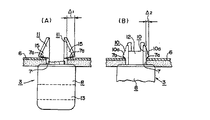
【図17】同ホルダと透孔との係合状態を示しており、(A)は係合前の状態を、(B)は仮固定の状態を、(C)は本固定の状態を夫々示す要部拡大断面図である。
【図18】この発明の実施の第3形態例に係るホルダを示す斜視図である。
【図19】車両用サンバイザを説明するための要部斜視図である。
【図20】図19のB部拡大図である。
【符号の説明】
1 サンバイザ
3,30,40 ホルダ
6 ルーフライニング
7 透孔
7a ,7b 縁部
8 基部
9 通孔
9a 縁部
10 第一の弾性係止脚
10a 傾斜突部
11 第二の弾性係止脚
11A 平板係止脚
12 挿入部材
13 フック
14 柱部
15 係止片
16a ,16b
17 ストッパ壁
19 回動板部
23 天井部
24 枢軸
25 軸部[0001]
BACKGROUND OF THE INVENTION
The fastening device according to the present invention is provided, for example, at a base portion of a holder that holds a shaft portion attached to a vehicle sun visor. It is related with the fastening tool which can be fastened to the through-hole formed in the.
[0002]
[Prior art]
Conventionally, a sun visor has been installed in the vicinity of the front upper part of a driver's seat or the like in an automobile interior in order to protect passengers' eyes from light such as sunlight and ensure safe driving. That is, the sun visor is provided in order to block light coming from the windshield in front of the vehicle. 19 and 20, such a sun visor is rotatably provided by a
[0003]
By the way, when the holder 27 is fixed to the
[0004]
[Problems to be solved by the invention]
However, the invention described in the above publication has the following disadvantages. That is, when the holder 27 is attached to the
[0005]
The fastening device according to the present invention was created in view of the above-described circumstances, and can be easily and reliably attached to a wall surface to be attached with a light force, and can be easily detached as necessary. The purpose is to provide a fastening device.
[0006]
[Means for Solving the Problems]
The fastening device according to the present invention is a fastening device that can be fastened from one side of the vehicle roof lining to a through hole formed in the vehicle roof lining, as described in claim 1, A base, one end on one side of the base, the other end on the other side of the base, and a through hole that opens to the other side of the base, and one edge of the base extending from opposite edges of the through hole A pair of first elastic locking legs parallel to each other, which are respectively engaged with mutually opposing edges of the through hole, and extending from one side surface of the base side by side with the first elastic locking legs, The other side of the vehicle roof lining is formed so as to protrude larger outward than the first through hole than the first elastic locking leg, and engages with each of the edges. A pair of second elastic locking legs, A stopper wall that is formed on one side surface of the base portion and abuts with an edge portion in a direction intersecting with an edge portion with which the pair of second elastic locking legs are engaged, and one end portion of the base portion. And can be inserted into the through-hole by rotation, and at least the first elastic locking leg among the first and second elastic locking legs along with the insertion. And an insertion member that presses in a direction to engage with the peripheral edge of the through hole, and the locking pieces of the pair of second elastic locking legs are in the vicinity of the corners of the through hole, each outward. It engages in the state which goes to, It is characterized by the above-mentioned.
[0007]
The operation when the fastening device according to claim 1 configured as described above is attached to the vehicle roof lining through the through hole provided in the vehicle roof lining is as follows. That is, the first and second elastic locking legs provided in pairs are inserted into the through holes while being elastically deformed. In this state, the first elastic locking leg is lightly engaged with the edge of the through hole, and the second elastic locking leg is engaged with the edge of the through hole (temporarily fixed state). In this temporarily fixed state, the fasteners are engaged at four positions, so the fasteners are not prepared even if the vehicle roofing with the fasteners temporarily fixed is conveyed as an example. Never leave. As a result, so-called modularization promoted from the viewpoint of manufacturing cost reduction or the like can be achieved. That is, in a state where the fastening device is temporarily fixed to the vehicle roof lining, the vehicle roof lining is transported to another location, and the vehicle roof lining is assembled to another member or the like at the other location. Further, the fastening device can be permanently fixed as described below. In the present invention, since the stopper wall is provided at the base portion, the second elastic locking leg must be provided at a certain distance from the stopper wall due to manufacturing requirements such as a mold structure. In the present invention, the second elastic locking leg is located near the corner where the strength of the through-hole is large, and each of them is directed outward. Since it is formed in a C shape so as to be engaged in a state, the engaging force of the second elastic locking leg can be maintained.
[0008]
Further, in order to change from the temporarily fixed state to the fully fixed state, the insertion member is rotated toward the through hole and inserted into the through hole. As a result, the pair of first elastic locking legs extending from the opposite edge portions of the through hole on one side surface of the base portion are pressed in a direction to be more strongly engaged by the opposite edge portions of the through holes. Therefore, the first elastic locking leg is firmly engaged with each edge portion. As a result, the first and second elastic locking legs are engaged at the four positions on the peripheral edge of the through hole. In particular, since the first elastic locking leg is firmly engaged with the insertion of the insertion member, the first elastic locking leg does not easily fall off after being attached (mainly fixed state).
[0009]
In addition, since the insertion member is provided, it is not necessary to keep the shape of the first elastic locking leg in a free state to be warped so as to increase the engagement allowance. Since it can stand upright, it can be easily attached to the wall surface with a light force. When it is desired to remove the fastening device from the fixed state, the insertion member is first extracted from the through hole. As a result, the first elastic locking leg returns to the free state and is lightly engaged with the edge of the through hole. Next, the other end of the base is rotated toward the one side with the base ends of the first and second elastic locking legs on one side of the base as a fulcrum. As a result, the first and second elastic locking legs on the other side come out of the through hole while being elastically deformed. After the first and second elastic locking legs on the other side come out of the through hole, the first and second elastic locking legs on the one side easily come out of the through hole. . Therefore, it can be easily removed from the fixed state.
[0010]
In addition to the above-described configuration, a stopper wall that abuts the edge in the direction intersecting with the edge engaged with the pair of second elastic locking legs among the edges of the through hole is formed on the base. Since the structure provided on one side surface is adopted, it is possible to prevent the fastening device after the attachment from moving in a direction crossing the edge portion with which the pair of second elastic locking legs are engaged. Can be securely fixed.
[0011]
In the invention according to
[0012]
Furthermore, in the present invention, as described in claim 4, a fastener that can be secured from one side of the vehicle roof lining to the through hole formed in the vehicle roof lining, A base, one end on one side of the base, the other end on the other side of the base, and a through hole that opens to the other side of the base, and one edge of the base extending from opposite edges of the through hole A pair of first elastic locking legs parallel to each other, which are respectively engaged with mutually opposing edges of the through hole, and extending from one side surface of the base side by side with the first elastic locking legs, The other side of the vehicle roof lining is formed so as to protrude larger outward than the first through hole than the first elastic locking leg, and engages with each of the edges. A pair of second elastic locking legs provided in a shape; The base is provided at one end of the base so as to be freely rotatable, and can be inserted into the through-hole by turning, and the first and second elastic locking legs are attached to the periphery of the through-hole with the insertion. An insertion member that presses in the direction in which the pair of second elastic locking legs is engaged, and the locking pieces of the pair of second elastic locking legs are engaged in the vicinity of the corners of the through holes in a state where each is directed outward. Therefore, when the insertion member is inserted, the second elastic locking leg can be pressed together with the first elastic locking leg, and both the first and second elastic locking legs can be pressed. It can be firmly engaged with the edge of the through-hole, and the final fixed state of the fastening can be made stronger, and at that time, the insertion member can be securely attached to the second elastic locking leg. When the second elastic locking leg is placed closer to the insertion member so as to be pressed against the center of the hole, and as a result, it engages closer to the center of the through hole having a lower strength Even so, the second elastic engagement legs are formed in a C shape in the vicinity of the corner where the strength of the through-hole is large so that each of the second elastic engagement legs faces outward. The engaging force of the stop leg can be maintained.
[0013]
DETAILED DESCRIPTION OF THE INVENTION
Hereinafter, the present invention will be described in detail based on embodiments of the invention shown in the accompanying drawings.
[0014]
1 to 10 show a fastening device according to a first embodiment of the present invention, and the fastening device according to this embodiment includes the shaft portion 26 (see FIG. 20) of the sun visor 1 described above. This is applied to the
[0015]
On one surface side of the base 8 (the lower surface side in FIGS. 1 to 4, the back surface side in FIG. 5A, the lower surface side in FIGS. 5C, D, and 6A), the sun visor is provided. A
[0016]
The through
[0017]
The pair of first
[0018]
The pair of second elastic locking
[0019]
In the case of the present embodiment, the lower surfaces of the locking
[0020]
The
[0021]
In the case of this embodiment, when the
[0022]
Further, in the case of the present embodiment, among the edge portions of the through-
[0023]
The operation of attaching the
[0024]
Further, when the
[0025]
As described above, the first and second elastic locking
[0026]
When the
[0027]
Furthermore, in the case of this embodiment, the presence of the
[0028]
In this embodiment, as shown in FIGS. 1 to 4, the side surface of the
[0029]
Further, a
[0030]
In the case of the illustrated example, the
[0031]
In the above-described example, the second elastic locking
[0032]
11 to 16 show a
[0033]
That is, the
[0034]
In addition, the
[0035]
The
[0036]
FIG. 18 shows a
[0037]
In other words, in the
[0038]
Therefore, in the
[0039]
In each of the above-described embodiments, the example in which the fastening device according to the present invention is applied to the
[0040]
【The invention's effect】
Since the fastening device according to the present invention is configured and operates as described above, the fastening device according to claim 1 can be easily and reliably attached to the vehicle roofing to be attached with a light force. it can. That is, when temporarily fixing to the vehicle roof lining, it is only necessary to press it toward the through hole formed in the vehicle roof lining. Even in the case of the main fixing, it is only necessary to press the insertion member while rotating the insertion member toward the through hole formed in the base portion. And since it engages at the position of at least four places, the engagement with the vehicle roof lining of the said fastening tool is strong, and can fix a fastening tool reliably. Moreover, it can remove easily by extracting an insertion member from a hole. As a result, so-called modularization can be changed, and a large practical effect can be obtained. In particular, when the vehicle roof lining is a soft material such as vehicle roof lining, the strength is lower near the center of the through hole of the vehicle roof lining, and the strength is increased at the corner of the through hole. Therefore, since each locking piece is directed to the corner of the through hole, it can be engaged at a portion having high rigidity, and the fixed state can be further strengthened.
[0041]
Further, in the fastening device described in
[0042]
Furthermore, in the fastening device according to
[0043]
Furthermore, in the fastening device according to claim 4, when the insertion member is inserted, the second elastic locking leg can be pressed together with the first elastic locking leg. The second elastic locking legs can be firmly engaged with the edge of the through hole, and the final fixed state of the fastening can be made stronger.
[Brief description of the drawings]
FIG. 1 is a perspective view of a holder according to a first embodiment of the present invention.
FIG. 2 is a perspective view showing a state before the holder is attached.
FIG. 3 is a side view showing a state immediately before the holder is attached.
FIG. 4 is a side view showing a state after the holder is attached.
5A and 5B show a configuration of the holder, wherein FIG. 5A is a plan view, FIG. 5B is a front view, and FIG. 5C is a rear view.
FIG. 6 is a schematic rear view showing a state in which the holder is temporarily fixed (A) and fully fixed (B) with a part thereof omitted.
FIGS. 7A and 7B show a configuration of an engaging protrusion formed at the distal end portion of the insertion member of the holder, where FIG. 7A is a front view, FIG. 7B is a right side view, and FIG.
FIG. 8 is a schematic perspective view of a main part for explaining an engagement state of first and second elastic locking legs of the holder with a peripheral edge of a through hole.
FIG. 9 is a side view of an essential part showing a modification of the holder.
FIG. 10A is a plan view of relevant parts showing a holder structure according to a first embodiment, and FIG. 10B is a plan view of relevant parts showing a holder structure according to another modification.
FIG. 11 is a perspective view of a holder according to a second embodiment of the present invention.
FIG. 12 is a front view of the holder.
FIG. 13 is a rear view of the holder.
FIG. 14 is a plan view of the holder.
FIG. 15 is a bottom view of the holder.
FIG. 16 is a left side view of the holder.
FIGS. 17A and 17B show an engaged state between the holder and the through-hole, where FIG. 17A shows a state before engagement, FIG. 17B shows a temporarily fixed state, and FIG. 17C shows a final fixed state; It is a principal part expanded sectional view shown.
FIG. 18 is a perspective view showing a holder according to a third embodiment of the present invention.
FIG. 19 is a perspective view of relevant parts for explaining a vehicle sun visor.
20 is an enlarged view of part B in FIG. 19;
[Explanation of symbols]
1 Sun visor
3, 30, 40 holder
6 roofing
7 Through hole
7a, 7b edge
8 base
9 through holes
9a edge
10 First elastic locking leg
10a Inclined protrusion
11 Second elastic locking leg
11A Flat stop leg
12 Insertion member
13 hook
14 pillars
15 Locking piece
16a, 16b
17 Stopper wall
19 Rotating plate
23 Ceiling
24 Axis
25 Shaft
Claims (4)
Priority Applications (1)
| Application Number | Priority Date | Filing Date | Title |
|---|---|---|---|
| JP2000119643A JP3772253B2 (en) | 1999-04-23 | 2000-04-20 | Fastener |
Applications Claiming Priority (3)
| Application Number | Priority Date | Filing Date | Title |
|---|---|---|---|
| JP11708499 | 1999-04-23 | ||
| JP11-117084 | 1999-04-23 | ||
| JP2000119643A JP3772253B2 (en) | 1999-04-23 | 2000-04-20 | Fastener |
Publications (2)
| Publication Number | Publication Date |
|---|---|
| JP2001003911A JP2001003911A (en) | 2001-01-09 |
| JP3772253B2 true JP3772253B2 (en) | 2006-05-10 |
Family
ID=26455268
Family Applications (1)
| Application Number | Title | Priority Date | Filing Date |
|---|---|---|---|
| JP2000119643A Expired - Fee Related JP3772253B2 (en) | 1999-04-23 | 2000-04-20 | Fastener |
Country Status (1)
| Country | Link |
|---|---|
| JP (1) | JP3772253B2 (en) |
Families Citing this family (7)
| Publication number | Priority date | Publication date | Assignee | Title |
|---|---|---|---|---|
| JP4683858B2 (en) * | 2004-05-14 | 2011-05-18 | スリーエム イノベイティブ プロパティズ カンパニー | Article support |
| JP2008049802A (en) * | 2006-08-24 | 2008-03-06 | Piolax Inc | Clip |
| JP5240446B2 (en) * | 2008-08-22 | 2013-07-17 | スズキ株式会社 | Cowl top garnish |
| JP5004137B2 (en) * | 2008-10-14 | 2012-08-22 | ダイキョーニシカワ株式会社 | Two-component mounting structure |
| JP5218144B2 (en) * | 2009-02-23 | 2013-06-26 | 船井電機株式会社 | Optical disk device |
| JP5993161B2 (en) * | 2012-02-29 | 2016-09-14 | サトーホールディングス株式会社 | Opening and closing device and printer having the opening and closing device |
| CN113246700A (en) * | 2021-06-15 | 2021-08-13 | 东风柳州汽车有限公司 | Fastening connection structure and ceiling mounting structure |
-
2000
- 2000-04-20 JP JP2000119643A patent/JP3772253B2/en not_active Expired - Fee Related
Also Published As
| Publication number | Publication date |
|---|---|
| JP2001003911A (en) | 2001-01-09 |
Similar Documents
| Publication | Publication Date | Title |
|---|---|---|
| US6672027B2 (en) | Pillar trim mounting structure | |
| EP1995097B1 (en) | Fixing clip for interior part of vehicle | |
| US6969100B2 (en) | Mounting structure and mounting method for vehicle interior parts | |
| US5507545A (en) | Visor clip assembly and releasable fastener | |
| WO2007126201A1 (en) | Automotive fastener | |
| US6824201B2 (en) | Pillar trim structure | |
| JP3772253B2 (en) | Fastener | |
| JP4070511B2 (en) | Mounting structure and mounting method for automotive interior parts | |
| JP3333745B2 (en) | Inside door handle device for vehicles | |
| JP4454790B2 (en) | Bearing holder for vehicle sun visor | |
| US5782527A (en) | Accessory for sunroof air deflector | |
| JP3491269B2 (en) | Fastener | |
| JP2003002120A (en) | Structure of rear gate for vehicle | |
| GB2333800A (en) | Anti-rotation mounting clip | |
| JP3115242B2 (en) | Sliding roof carrier for vehicles | |
| JP2001260651A (en) | Supporting hook of sunvisor for automobile | |
| JP2002178766A (en) | Flexible blind attachment structure for vehicle sun roof | |
| JPH08310299A (en) | Vehicle map lamp arrangement structure | |
| JPH05238337A (en) | Method for mounting vehicular bumper end on car body | |
| JPS5911771Y2 (en) | Automobile sunshade opening/closing device | |
| JP2518222Y2 (en) | Clip for door molding | |
| JP2000087600A (en) | Inside door handle device for car | |
| JP2001063484A (en) | Pillar garnish | |
| EP0006332B1 (en) | Mounting extended area articles by attachment system co-operating with edge regions of the articles | |
| JPH11222081A (en) | Mounting structure of molding roof for vehicle |
Legal Events
| Date | Code | Title | Description |
|---|---|---|---|
| A977 | Report on retrieval |
Free format text: JAPANESE INTERMEDIATE CODE: A971007 Effective date: 20050914 |
|
| A131 | Notification of reasons for refusal |
Free format text: JAPANESE INTERMEDIATE CODE: A131 Effective date: 20050920 |
|
| A521 | Written amendment |
Free format text: JAPANESE INTERMEDIATE CODE: A523 Effective date: 20051121 |
|
| TRDD | Decision of grant or rejection written | ||
| A01 | Written decision to grant a patent or to grant a registration (utility model) |
Free format text: JAPANESE INTERMEDIATE CODE: A01 Effective date: 20060127 |
|
| A61 | First payment of annual fees (during grant procedure) |
Free format text: JAPANESE INTERMEDIATE CODE: A61 Effective date: 20060131 |
|
| R150 | Certificate of patent or registration of utility model |
Free format text: JAPANESE INTERMEDIATE CODE: R150 |
|
| LAPS | Cancellation because of no payment of annual fees |