JP3772064B2 - Fire detection method and alarm - Google Patents
Fire detection method and alarm Download PDFInfo
- Publication number
- JP3772064B2 JP3772064B2 JP2000058581A JP2000058581A JP3772064B2 JP 3772064 B2 JP3772064 B2 JP 3772064B2 JP 2000058581 A JP2000058581 A JP 2000058581A JP 2000058581 A JP2000058581 A JP 2000058581A JP 3772064 B2 JP3772064 B2 JP 3772064B2
- Authority
- JP
- Japan
- Prior art keywords
- fire
- sensor
- wind speed
- detecting
- alarm
- Prior art date
- Legal status (The legal status is an assumption and is not a legal conclusion. Google has not performed a legal analysis and makes no representation as to the accuracy of the status listed.)
- Expired - Fee Related
Links
Images


Description
【0001】
【発明の属する技術分野】
本発明は、火災検知方法及び火災警報器に関する。特には、火災発生をより早期に検知する方法及び警報器に関する。
【0002】
【従来の技術及び発明が解決しようとする課題】
台所等に設置される火災警報器は、温度や火災時に発生するガスの濃度を検出して火災を検知し、警報を発するものが一般に使用されている。また、燃焼ガスの不完全燃焼時に発生するガス濃度や燃焼ガス濃度を検出するセンサを備え、不完全燃焼やガス洩れを検知する機能を備えた火災警報器もある。
しかし、近年では、現状よりも早期に火災を検知するシステムが求められている。
【0003】
一方、特開平11−232565号には、電気ケーブルや通信ケーブルを敷設した密閉空間(暗渠)内の火災を検知する方法が開示されている。この方法は暗渠内の長さ方向の複数箇所で、天井付近、中間付近、床付近の風速を測定するものである。すなわち、火災が暗渠内の一部で発生すれば、天井付近と床付近で風速や風向も変化することから、暗渠内の複数箇所で風速や風向を測定して早期に火災の発生を検知している。
【0004】
しかしながら、同号の方法は、複数の風速センサを必要とし、家庭の台所やオフィスビルのような場所に適したものとはいえない。一方、そのような場所用の火災検知システムでは、より早く火災を検知できるとともに、誤報率の低いシステムが求められている。
【0005】
本発明は、上記の課題を解決するためになされたものであって、火災をより早期に検知できる火災検知方法及び火災警報器を提供することを目的とする。
【0006】
【課題を解決するための手段及び発明の実施の形態】
上記の課題を解決するため、本発明の火災警報方法は、建物内の環境要素に関する現象を検出するセンサと、該センサからの信号を入力されて火災発生を判定する判定部と、該判定部の判定結果を表示する表示部と、を具備する火災検知システムを用いて火災検知する方法であって;上記センサとして、熱、燃焼生成ガス又は煙を検知するセンサのいずれか1あるいは2以上と、上記建物内の風速を検出するセンサと、を建物内の部屋の天井又は壁の上部に取り付け、発炎火災の発生初期における天井付近の風速や壁付近の風速の立ち上がりを検出して火災発生を判定することを特徴とする。
【0007】
火災発生時には、詳しくは後述するように温度上昇よりも風速の方が立ち上がりが早い。この風速を測定する風速センサを備えたことで、火災をより早期に検知することができる火災検知方法を提供することができる。また火災の発生を風速や他の物理現象(温度変化やガス濃度変化)を含めて判定するため、より確実な判定を行うことができる。さらに、燃焼ガスや燃焼生成ガスを検知するセンサを備えれば、ガス洩れや不完全燃焼も検知することができる。
【0008】
本発明の具体的態様の火災検知システムは、 建物内の温度を検出するセンサと、 建物内の風速を検出するセンサと、 上記両センサからの信号を入力されて火災発生を判定する判定部であって、上記風速センサの検出する風速があるしきい値以上であり、かつ上記温度センサが検出する温度があるしきい値以上であるときに火災発生と判定する判定部と、 該判定部の判定結果を表示する表示部と、を具備することを特徴とする。
【0009】
あるいは、上記判定部が、上記風速センサの検出する風速があるしきい値以上であり、かつ上記温度センサが検出する温度の上昇速度があるしきい値以上であるときに火災発生と判定することとしてもよい。
あるいは、上記風速センサの検出する風速の上昇度があるしきい値以上であり、かつ上記温度センサが検出する温度があるしきい値以上であるときに火災発生と判定することとしてもよい。
あるいは、上記風速センサの検出する風速の上昇度があるしきい値以上であり、かつ上記温度センサが検出する温度の上昇速度があるしきい値以上であるときに火災発生と判定することとしてもよい。
火災発生初期に変化が大きい風速、風速の上昇度、温度、温度の上昇度を各しきい値と比較することによって、より早期に火災の検知を行うことができる。
【0010】
本発明の第1態様の火災警報器は、温度を検出するセンサと、風速を検出するセンサと、上記両センサからの信号を入力されて火災発生を判定する判定部と、該判定部の判定に応じて警報を発する警報部と、を具備し、上記各センサ及び各部が一体のケーシングに配置されており、該警報器は建物内の部屋の天井又は壁の上部に取り付けられて、発炎火災の発生初期における天井付近の風速や壁付近の風速の立ち上がりを検出して火災発生を判定することを特徴とする。
【0011】
この態様においては、 温度があるしきい値を越え、かつ、風速があるしきい値を越えたときに火災発生と判定できる。
あるいは、 温度の上昇速度があるしきい値を越え、かつ、風速があるしきい値を越えたときに火災発生と判定することとしてもよい。
あるいは、 温度があるしきい値を越え、かつ、風速の上昇度があるしきい値を越えたときに火災発生と判定することとしてもよい。
あるいは、 温度の上昇速度があるしきい値を越え、かつ、風速の上昇度があるしきい値を越えたときに火災発生と判定することとしてもよい。
火災発生初期に変化が大きい風速、風速の上昇度、温度の上昇度を各しきい値と比較することによって、より早期に火災の検知を行うことのできる警報器を提供することができる。
【0012】
本発明の第2態様の火災警報器は、感熱センサと、COガス濃度を検出するセンサと、風速を検出するセンサと、上記センサからの信号を入力されて、不完全燃焼及び火災を判定する判定部と、該判定部の判定に応じて警報を発する警報部と、を具備し、上記各センサ及び各部が一体のケーシングに配置されており、該警報器は建物内の部屋の天井又は壁の上部に取り付けられて、発炎火災の発生初期における天井付近の風速や壁付近の風速の立ち上がりを検出して火災発生を判定することを特徴とする。
【0013】
この態様においては、 上記COガス濃度センサで検出されたCOガス濃度が第1のしきい値を超えたことでもって不完全燃焼と判定し、 上記風速センサで検出された風速があるしきい値を越えるか、又は、COガス濃度が第2のしきい値を越えるか感熱センサで検出された感熱量があるしきい値を越えたことでもって火災発生と判定することができる。
不完全燃焼と発炎火災発生を早期に検知し、警報を発することができる。
【0014】
本発明の第3態様の火災警報器は、炭化水素ガス濃度を検出するセンサと、COガス濃度を検出するセンサと、風速を検出するセンサと、上記センサからの信号を入力されて、ガス洩れ、不完全燃焼及び火災を判定する判定部と、該判定部の判定に応じて警報を発する警報部と、を具備し、上記各センサ及び各部が一体のケーシングに配置されており、該警報器は建物内の部屋の天井又は壁の上部に取り付けられて、発炎火災の発生初期における天井付近の風速や壁付近の風速の立ち上がりを検出して火災発生を判定することを特徴とする。
【0015】
この態様においては、 上記炭化水素ガス濃度センサで検出された炭化水素ガス濃度が第1のしきい値を超えたことでもってガス洩れと判定し、 上記COガス濃度センサで検出されたCOガス濃度が第1のしきい値を超えたことでもって不完全燃焼と判定し、 上記風速センサで検出された風速があるしきい値を越えるか、又は、炭化水素ガス濃度が第2のしきい値を超えるかCOガス濃度が第2のしきい値を越えたことでもって火災発生と判定することができる。
ガス漏れ、不完全燃焼、発炎火災発生を早期に検知し、警報を発することができる。
【0016】
本発明の第4態様の火災警報器は、炭化水素ガス濃度を検出するセンサと、COガス濃度を検出するセンサと、感熱センサと、風速を検出するセンサと、上記センサからの信号を入力されて、ガス洩れ、不完全燃焼及び火災を判定する判定部と、該判定部の判定に応じて警報を発する警報部と、を具備し、上記各センサ及び各部が一体のケーシングに配置されており、該警報器は建物内の部屋の天井又は壁の上部に取り付けられて、発炎火災の発生初期における天井付近の風速や壁付近の風速の立ち上がりを検出して火災発生を判定することを特徴とする。
【0017】
この態様においては、 上記炭化水素ガス濃度センサで検出された炭化水素ガス濃度がしきい値を越えたことでもってもってガス洩れと判定し、 上記COガス濃度センサで検出されたCOガス濃度が第1のしきい値を越えたことでもって不完全燃焼と判定し、 上記風速センサで検出された風速があるしきい値を越えるか、又は、感熱センサの感熱量がしきい値を越えるかCOガス濃度が第2のしきい値を越えたことでもって火災発生と判定することができる。
ガス漏れ、不完全燃焼、発炎火災発生を早期に検知し、警報を発することができる。
【0018】
本発明の第5態様の火災警報器は、炭化水素ガス濃度を検出するセンサと、COガス濃度を検出するセンサと、煙を感知するセンサと、風速センサと、上記センサからの信号を入力されて、ガス洩れ、不完全燃焼及び火災を判定する判定部と、該判定部の判定に応じて警報を発する警報部と、を具備し、上記各センサ及び各部が一体のケーシングに配置されており、該警報器は建物内の部屋の天井又は壁の上部に取り付けられて、発炎火災の発生初期における天井付近の風速や壁付近の風速の立ち上がりを検出して火災発生を判定することを特徴とする。
【0019】
この態様においては、 上記炭化水素ガスセンサで検出された炭化水素ガス濃度がしきい値を越えたことでもってガス洩れと判定し、 上記COガス濃度センサで検出されたCOガス濃度が第1のしきい値を越えたことでもって不完全燃焼と判定し、 上記風速センサで検出された風速があるしきい値を越えるか、又は、上記煙センサで煙が検出されかつCOガス濃度が第2のしきい値を越えたとでもって火災発生と判定することができる。
ガス漏れ、不完全燃焼、発炎及び発煙火災を早期に検知し、警報を発することができる。
【0020】
以下、火災発生時の室内の風速や温度変化について確認するために、本発明者らが行った実験について説明する。
より早期に火災を検知できる火災警報器として、風速や風向を考慮し、台所等での火災発生時に風速や風向にどのような変化が起こるかを、規定(Components of automatic fire detection system Part 9. Methods of test of sensitivity to fire)に基づいて計測した。
【0021】
実験条件を以下に示す。
試験室の大きさ:幅=10m、奥行き=6m、高さ=4m
初期環境条件:温度=23±5℃、煙濃度(イオン化)<0.05、煙濃度(光学的)<0.05dB/m
【0022】
試験用火元:
(1)TF1:セルロース火災(木片)
約70本のブナ材片(1×2×25cm3)を試験室の中央に置かれたベース上に7層に積み上げ、5cm3の変性アルコールで点火する。
(2)TF2:いぶした高温加熱火災(木片)
約70本のブナ材片(体積1×2×25cm3)をホットプレート上に星型に配置し、11分以内に600℃に達する火力でいぶす。
(3)TF3:いぶし火(コットン片)
90個のコットン片(重量3g、長さ80cm)を乾燥させ、径が10cmのリングに固定し、端部に点火した。
【0023】
(4)TF4:プラスチック火災(ポリウレタン)
3枚のポリウレタンフォーム(体積1×2×25cm3、密度20Kg/cm3)をアルミ箔上に置き、5cm3の変性アルコールで点火する。
(5)TF5:液体火災(n−ヘプタン)
n−ヘプタンと3重量%のトルエンを容器(底面積1100cm2、高さ5cm)に入れ、点火する。
(6)TF6:液体火災(変性アルコール)
少なくとも90%エタノールの変性アルコールを容器(底面積1900cm2、高さ5cm)に入れ、点火する。
この中で、TF2、TF3は主に煙が発生する火災(発煙火災)、TF5、TF6は主に炎が発生する火災(発炎火災)に相当する。台所火災の火元は、このTF5やTF6の火元に近い。
【0024】
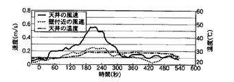
各試験用火元での火災発生時に、天井付近の風速、壁付近の風速、天井の温度を計測したグラフを図7〜12に示す。各グラフの横軸は時間(秒)であり、0が点火時である。縦軸は風速及び温度である。グラフ中の実線は天井の風速、破線は壁付近の風速、一点鎖線は天井の温度である。各グラフの図7〜12は上記試験用火元TF1〜6に対応している。
【0025】
測定条件を以下に示す。
(1)計測位置
天井付近の風速:火元(実験室中央)から3m離れた位置
天井の温度:火元(実験室中央)から3m離れた位置
(2)計測機器
風速:クリーンルーム用3次元超音波風速計「マイクロソニックWA−390型」(株式会社カイジョー社製)
測定範囲;0〜±10m/s、測定精度;±2%、応答速度;0.5秒
温度:65℃
【0026】
これらの測定結果より、TF2、TF3の発煙火災の場合は、風速や温度に大きな変化はみられない。また、天井付近の温度にも変化がない。
TF1、TF4の木片やプラスチックの火災の場合は、天井付近の風速や壁付近の風速が徐々に上昇し、その後下降する。天井付近の温度は徐々に上昇する。
TF5、TF6の発炎火災の場合、点火後30秒以内に急速に天井付近の風速が上昇している。また、壁付近の風速も点火後60秒以内に風速の上昇が起こっている。天井付近の温度は徐々に上昇している。
【0027】
次に、台所火災を想定したTF6において、温度、煙濃度、燃料の重量、CO濃度、CO2濃度、O2濃度、NO濃度、NOX濃度、NO2濃度を上述の測定条件で測定した。ここで、COは燃焼ガスの不完全燃焼時や火災初期に発生する。CO2は不完全燃焼や本格的な火災時に発生する。O2濃度は不完全燃焼時や本格的な火災時に低下する。
【0028】
図13、14は、TF6における温度、煙濃度、燃料の重量、CO濃度、CO2濃度、O2濃度、NO濃度、NOX濃度、NO2濃度の変化を示すグラフである。
通常の温度検知式の火災検知システムは、温度が65℃に達すると作動するものが多い。図12に見られるように、温度(実線)が65℃に達するまでに火災発生から約2分が経過していることとなる。また、CO濃度、CO2濃度、NO濃度、NOX濃度、NO2濃度も上昇しているが立ち上がりは緩やかである。この条件では、燃焼の性質から煙の発生量は低い。
なお、図12と図13の温度推移が異なるのは、図12は天井面に接した部分の温度、図13は天井から5cm下の気流温度を計測しているためである。
【0029】
以上の実験結果より、台所火災の火元に相当するTF6の実験において、火災発生初期に大きく変化する物理要素は天井付近の風速や壁付近の風速であることが確認される。特に天井付近の風速は火災発生から30秒以内での急激な立ち上がりが特徴的である。一方、温度やNO濃度、NOX濃度、NO2濃度、CO濃度、CO2濃度も上昇しているが、立ち上がりが緩やかである。
【0030】
以下、本発明の火災検知システム及び警報器の実施例について、図面を参照しつつ説明する。
図1は、本発明の実施例に係る火災警報器の構成を示すブロック図である。
この警報器1は、火災センサとして感熱センサ11及び風速センサ13、ガスセンサとしてCOガスセンサ15及び炭化水素ガスセンサ17の四つのセンサを備えている。各センサの出力信号は、マイコン等で構成される判定部21に送られる。判定部21は各センサからの信号を処理して、火災発生、ガス洩れ、不完全燃焼等を判定する。その結果は音声警報部23や液晶表示部25に送られて表示される。
【0031】
風速センサ13は、上述の超音波風速計や熱線型の風速センサが使用される。超音波風速計は、超音波が空気中を伝播するときに、風速に比例して伝播時間が変化することを利用したもので、温度や湿度の影響を受けずに正確に風速を測定することができる(クリーンルーム用3次元超音波風速計「マイクロソニックWA−390型」(株式会社カイジョー社製)等)。熱線型風速センサは、ヒータを中心として上流及び下流に温度センサが配置されたものであり、静止状態ではヒータを中心とした対称な温度分布を形成している。空気の流れが生じると温度分布が崩れ、このときの温度センサの抵抗値の差から流速を求める(「気体用マスフローメータCMS20/50」(山武ハネウエル株式会社製等))。なお、これらの風速計やセンサは精密計測用で現在では高価であるが、精度要求を下げて量産すれば価格は相当下がるものと思われる。さらに、他の計測原理に基づくセンサも用いることができる。
【0032】
感熱センサ11としては、サーミスタや熱電対等の温度センサや、赤外線センサ、紫外線センサ、焦電センサが使用される。ガスセンサは主に半導体式が使用される。COガスセンサ15は、燃焼ガスの不完全燃焼時や火災初期に発生するCOガスを検知する。炭化水素ガスセンサ17は、都市ガスの主成分であるメタンの漏れや火災初期に発生する炭化水素ガスを検知する。
【0033】
図2は、図1の火災警報器が設置される台所の構造を示す図である。
火災警報器1は、火元(ガステーブル等)51から8m以内の天井又は壁に設置することが決められている。
通常、ガス台21の上方には換気扇53が設置されている。換気扇53の吸い込み風速は、通常0.4m/s以下に設定されている。また、台所には室内に開くドア55や外部に開くドアが設けられている。これらのドアを開いたときに、台所の気流の速度は0.5〜1.0m/sとなるように設計されている(「最新建築環境工学」井上書院)。
図3は、本発明の実施例に係るオフィスビル等における集中式の火災検知システムを示すブロック図である。
部屋A及び部屋B、廊下には、警報器31と、スピーカ33等の音声発生器が備えられている。この例の警報器31は、図1に示す各センサのみを備えたものであり、図1に示す判定部はビルを管理する防災保安用コンピュータ35に設けられている。各センサで検出される値は配線を通って防災保安用コンピュータ35の判定部37に送られ、所定の値と比較されて火災発生や他の緊急事態の発生を判定する。警報器31は部屋の広さや火元の数に応じて複数台設置される。この図では、部屋Aに2台設置されている。各スピーカ33は館内放送装置39に配線で接続されている。館内放送装置39は防災保安用コンピュータ35に接続している。
【0034】
このシステムの作用を火災発生時を例にとって説明する。
いずれかの部屋又は廊下で火災が発生すると、警報器31の各センサで検出された値は防災保安用コンピュータ35の判定部37に送られ、判定部37が火災発生と判定する。そして判定部37から館内放送装置39に情報が送られ、各スピーカ33から警報や音声で火災が発生したことが報知される。
【0035】
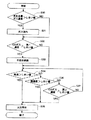
図4は、図1の火災警報器の判定パターンを説明するフローチャートである。
最初に、S10で炭化水素ガス濃度センサで検出された炭化水素ガス濃度をしきい値(一例0.2%)と比較する。炭化水素ガス濃度がしきい値より高ければS11でガス洩れと判定される。次に、S12でCOガス濃度センサで検出されたCOガス濃度を第1しきい値(一例50ppm)と比較する。COガス濃度が第1しきい値より高ければS13で不完全燃焼と判定される。
【0036】
次に、S14で風速センサで検出された風速をしきい値(一例0.2〜0.3m/s)と比較する。風速がしきい値より高ければ、S15で火災発生と判定される。なお、S10、S12で炭化水素ガス濃度やCOガス濃度がしきい値より低い場合でも、S14で風速がしきい値と比較される。
【0037】
S14で風速がしきい値より低ければ、S16で感熱センサで検出された温度をしきい値(一例65℃)と比較する。温度がしきい値より高ければ、S15で火災と判定される。S16で温度がしきい値より低ければ、S17でCOガス濃度を第2しきい値(一例250ppm)と比較する。COガス濃度が第2しきい値より高ければ、S15で火災と判定される。
【0038】
図5は、本発明の他の実施例に係る火災警報器の判定パターンを説明するフローチャートである。
この例の警報器は、火災センサとして感熱センサ及び風速センサ、ガスセンサとしてCOガスセンサの三つのセンサを備えている。
最初に、S20で、COガスセンサで検出されるCOガス濃度をしきい値(一例50ppm)と比較する。COガス濃度がしきい値より高ければS21で不完全燃焼と判定する。
【0039】
次に、S22で風速センサで検出される風速をしきい値(一例0.2〜0.3m/s)と比較する。風速がしきい値より高ければ、S23で火災と判定する。S22で風速がしきい値より低ければ、S24で感熱センサで検出される温度をしきい値(一例65℃)と比較する。温度がしきい値より高ければ、S23で火災と判定する。
【0040】
図6は、本発明の他の実施例に係る火災警報器の判定パターンを説明するフローチャートである。
この例の火災警報器は、火災センサとして風速センサ及び煙センサ、ガスセンサとしてCOガスセンサ及び炭化水素ガスセンサの四つのセンサを備えている。風速センサ、COガスセンサ、炭化水素ガスセンサは、図1の例のものが使用される。煙センサは光減衰式やイオン電流式のものが使用される。
【0041】
最初に、S30で炭化水素ガス濃度センサで検出された炭化水素ガス濃度をしきい値(一例0.2%)と比較する。炭化水素ガス濃度がしきい値より高ければS31でガス洩れと判定される。次に、S32でCOガス濃度センサで検出されたCOガス濃度を第1しきい値(一例50ppm)と比較する。COガス濃度が第1しきい値より高ければS33で不完全燃焼と判定される。
【0042】
次に、S34で風速センサで検出された風速をしきい値(一例0.2〜0.3m/s)と比較する。風速がしきい値より高ければ、S35で火災発生と判定される。なお、S30、S32で炭化水素ガス濃度やCOガス濃度がしきい値より低い場合でも、S34で風速がしきい値と比較される。
【0043】
S34で風速がしきい値より低ければ、S36で煙センサで検出された煙濃度をしきい値(一例5%)と比較する。煙濃度がしきい値より高ければ、S35で火災と判定される。S36で煙濃度がしきい値より低ければ、S37でCOガス濃度を第2しきい値(一例250ppm)と比較する。COガス濃度が第2しきい値より高ければ、S35で火災と判定される。
この例においては、発煙する火災も検知することができる。
【0044】
これらの例では、風速センサで検出される風速を使用したが、風速の上昇度を使用してもよい。また、温度は温度の上昇速度を使用してもよい。
【0045】
【発明の効果】
以上の説明から明らかなように、本発明によれば、風速センサを火災警報器に備えたことにより、火災をより早期に検知することができる。また、ガスセンサを備えることで、ガス洩れや不完全燃焼の検知も同時に行うことができる。
【図面の簡単な説明】
【図1】本発明の実施例に係る火災警報器の構成を示すブロック図である。
【図2】図1の火災警報器が設置される台所の構造を示す図である。
【図3】本発明の実施例に係るオフィスビル等における集中式の火災検知システムを示すブロック図である。
【図4】図1の火災警報器の判定パターンを説明するフローチャートである。
【図5】本発明の他の実施例に係る火災警報器の判定パターンを説明するフローチャートである。
【図6】本発明の他の実施例に係る火災警報器の判定パターンを説明するフローチャートである。
【図7】試験用火元(TF1)での火災発生時に、天井付近の風速、壁付近の風速、天井の温度を計測したグラフを示す図である。
【図8】試験用火元(TF2)での火災発生時に、天井付近の風速、壁付近の風速、天井の温度を計測したグラフを示す図である。
【図9】試験用火元(TF3)での火災発生時に、天井付近の風速、壁付近の風速、天井の温度を計測したグラフを示す図である。
【図10】試験用火元(TF4)での火災発生時に、天井付近の風速、壁付近の風速、天井の温度を計測したグラフを示す図である。
【図11】試験用火元(TF5)での火災発生時に、天井付近の風速、壁付近の風速、天井の温度を計測したグラフを示す図である。
【図12】試験用火元(TF6)での火災発生時に、天井付近の風速、壁付近の風速、天井の温度を計測したグラフを示す図である。
【図13】TF6における温度、煙濃度、燃料の重量の変化を示すグラフである。
【図14】TF6におけるCO濃度、CO2濃度、O2濃度、NO濃度、NOX濃度、NO2濃度の変化を示すグラフである。
【符号の説明】
1、31 警報器 11 感熱センサ
13 風速センサ 15 COセンサ
17 炭化水素ガスセンサ 21、37 判定部
23 音声警報部 25 液晶表示部
33 スピーカ 35 防災保安用コンピュータ
39 館内放送装置[0001]
BACKGROUND OF THE INVENTION
The present invention relates to a fire detection method and a fire alarm. In particular, the present invention relates to a method for detecting the occurrence of a fire earlier and an alarm.
[0002]
[Prior art and problems to be solved by the invention]
A fire alarm installed in a kitchen or the like is generally used to detect a fire by detecting the temperature and the concentration of a gas generated at the time of a fire and issue an alarm. There is also a fire alarm device that includes a sensor that detects a gas concentration generated during incomplete combustion of combustion gas and a concentration of the combustion gas, and has a function of detecting incomplete combustion and gas leakage.
However, in recent years, there is a demand for a system that detects a fire earlier than the current situation.
[0003]
On the other hand, Japanese Patent Application Laid-Open No. 11-232565 discloses a method for detecting a fire in an enclosed space (underdrain) in which an electric cable or a communication cable is laid. This method measures the wind speed near the ceiling, near the middle, and near the floor at a plurality of locations in the length direction of the underdrain. In other words, if a fire occurs in a part of a culvert, the wind speed and direction also change near the ceiling and near the floor.Therefore, the occurrence of a fire is detected early by measuring the wind speed and direction at multiple locations in the culvert. ing.
[0004]
However, the method of the same number requires a plurality of wind speed sensors and is not suitable for a place such as a home kitchen or an office building. On the other hand, in such a fire detection system for a place, a system that can detect a fire earlier and has a low false alarm rate is required.
[0005]
The present invention has been made to solve the above-described problems, and an object of the present invention is to provide a fire detection method and a fire alarm capable of detecting a fire earlier.
[0006]
Means for Solving the Problem and Embodiment of the Invention
In order to solve the above problems, a fire alarm method of the present invention includes a sensor that detects a phenomenon related to an environmental element in a building, a determination unit that receives a signal from the sensor and determines the occurrence of a fire, and the determination unit the determination result to a method of fire detection using a display unit, the fire detection system comprising a displaying a; as the sensor, heat, any one or more sensors for detecting the combustion product gases or smoke and A sensor that detects the wind speed in the building is attached to the ceiling or the upper part of the wall of the room in the building, and a fire is generated by detecting the wind speed near the ceiling and the rise of the wind speed near the wall in the early stage of the fire. It is characterized by determining .
[0007]
When a fire occurs, the wind speed rises faster than the temperature rise, as will be described in detail later. By providing the wind speed sensor for measuring the wind speed, it is possible to provide a fire detection method capable of detecting a fire earlier. In addition, since the occurrence of fire is determined including wind speed and other physical phenomena (temperature change and gas concentration change), more reliable determination can be made. Furthermore, if a sensor for detecting combustion gas and combustion generated gas is provided, gas leakage and incomplete combustion can also be detected.
[0008]
A fire detection system according to a specific aspect of the present invention includes a sensor that detects a temperature in a building, a sensor that detects a wind speed in the building, and a determination unit that receives a signal from both the sensors and determines whether a fire has occurred. A determination unit that determines that a fire has occurred when the wind speed detected by the wind speed sensor is equal to or greater than a threshold value and the temperature detected by the temperature sensor is equal to or greater than a threshold value; And a display unit for displaying the determination result.
[0009]
Alternatively, the determination unit determines that a fire has occurred when the wind speed detected by the wind speed sensor is greater than or equal to a threshold value and the rate of temperature increase detected by the temperature sensor is greater than or equal to a threshold value. It is good.
Alternatively, it may be determined that a fire has occurred when the degree of increase in wind speed detected by the wind speed sensor is equal to or greater than a certain threshold value and the temperature detected by the temperature sensor is equal to or greater than a certain threshold value.
Alternatively, it may be determined that a fire has occurred when the increase rate of the wind speed detected by the wind speed sensor is equal to or greater than a threshold value and the increase rate of the temperature detected by the temperature sensor is equal to or greater than a threshold value. Good.
A fire can be detected earlier by comparing the wind speed, the increase in wind speed, the temperature, and the increase in temperature with the respective threshold values at the initial stage of the fire.
[0010]
A fire alarm device according to a first aspect of the present invention includes a sensor for detecting a temperature, a sensor for detecting a wind speed, a determination unit that receives a signal from both the sensors and determines whether a fire has occurred, and a determination by the determination unit An alarm unit that emits an alarm according to the above, each sensor and each unit are arranged in an integral casing , and the alarm device is attached to the ceiling of the room or the upper wall of the room in the building, It is characterized in that the occurrence of a fire is determined by detecting the rise of the wind speed near the ceiling or the wind speed near the wall in the early stage of the fire .
[0011]
In this embodiment, it can be determined that a fire has occurred when the temperature exceeds a certain threshold and the wind speed exceeds a certain threshold.
Alternatively, it may be determined that a fire has occurred when the temperature rise rate exceeds a certain threshold value and the wind speed exceeds a certain threshold value.
Alternatively, it may be determined that a fire has occurred when the temperature exceeds a certain threshold value and the degree of increase in wind speed exceeds a certain threshold value.
Alternatively, it may be determined that a fire has occurred when the temperature rise rate exceeds a certain threshold value and the wind speed rise rate exceeds a certain threshold value.
It is possible to provide an alarm device that can detect a fire at an earlier stage by comparing the wind speed, the increase in wind speed, and the increase in temperature with the threshold values, which have a large change in the early stage of the fire.
[0012]
A fire alarm device according to a second aspect of the present invention receives a thermal sensor, a sensor for detecting CO gas concentration, a sensor for detecting wind speed, and a signal from the sensor to determine incomplete combustion and fire. A determination unit, and an alarm unit that issues an alarm in response to the determination of the determination unit, wherein each of the sensors and each unit is arranged in an integral casing , and the alarm device is a ceiling or wall of a room in a building It is attached to the upper part of this, and the occurrence of a fire is determined by detecting the rise of the wind speed near the ceiling and the rise of the wind speed near the wall in the initial stage of the occurrence of the fire .
[0013]
In this aspect, when the CO gas concentration detected by the CO gas concentration sensor exceeds the first threshold value, it is determined that the combustion is incomplete, and the wind speed detected by the wind speed sensor is a certain threshold value. It is possible to determine that a fire has occurred if the CO gas concentration exceeds the second threshold value, or if the amount of heat detected by the thermal sensor exceeds a certain threshold value.
It can detect incomplete combustion and flaming fire at an early stage and issue an alarm.
[0014]
A fire alarm device according to a third aspect of the present invention includes a sensor that detects a hydrocarbon gas concentration, a sensor that detects a CO gas concentration, a sensor that detects a wind speed, and a signal from the sensor, and is configured to leak gas. A determination unit that determines incomplete combustion and a fire, and an alarm unit that issues an alarm in response to the determination of the determination unit, wherein each of the sensors and each unit is disposed in an integral casing , and the alarm device Is attached to the top of the ceiling or wall of the room in the building, and detects the occurrence of fire by detecting the wind speed near the ceiling and the rise of the wind speed near the wall in the early stage of the occurrence of the flaming fire .
[0015]
In this aspect, it is determined that the hydrocarbon gas concentration detected by the hydrocarbon gas concentration sensor has exceeded a first threshold value, so that the gas leaked, and the CO gas concentration detected by the CO gas concentration sensor. Exceeds the first threshold value, it is determined that the combustion is incomplete, and the wind speed detected by the wind speed sensor exceeds a certain threshold value, or the hydrocarbon gas concentration is a second threshold value. Or the CO gas concentration exceeds the second threshold value, it can be determined that a fire has occurred.
Gas leaks, incomplete combustion, and flaming fire can be detected early and alarms can be issued.
[0016]
A fire alarm device according to a fourth aspect of the present invention receives a sensor for detecting a hydrocarbon gas concentration, a sensor for detecting a CO gas concentration, a thermal sensor, a sensor for detecting wind speed, and a signal from the sensor. Te, gas leakage, a determination unit incomplete combustion and fire, anda warning unit for issuing an alarm in response to the determination of the determination unit, the sensors and respective parts are arranged integrally in the casing The alarm is attached to the ceiling or upper part of the wall of the room in the building, and detects the occurrence of fire by detecting the rise of the wind speed near the ceiling and the rise of the wind speed near the wall in the initial stage of the occurrence of the flame fire. And
[0017]
In this aspect, the hydrocarbon gas concentration detected by the hydrocarbon gas concentration sensor is judged to be a gas leak when the hydrocarbon gas concentration exceeds a threshold value, and the CO gas concentration detected by the CO gas concentration sensor is the first value. If the threshold value of 1 is exceeded, it is determined that the combustion is incomplete, and whether the wind speed detected by the wind speed sensor exceeds a certain threshold value, or whether the heat sensitive amount of the thermal sensor exceeds the threshold value, CO It can be determined that a fire has occurred when the gas concentration exceeds the second threshold.
Gas leaks, incomplete combustion, and flaming fire can be detected early and alarms can be issued.
[0018]
A fire alarm device according to a fifth aspect of the present invention receives a sensor for detecting a hydrocarbon gas concentration, a sensor for detecting a CO gas concentration, a sensor for detecting smoke, a wind speed sensor, and a signal from the sensor. Te, gas leakage, a determination unit incomplete combustion and fire, anda warning unit for issuing an alarm in response to the determination of the determination unit, the sensors and respective parts are arranged integrally in the casing The alarm is attached to the ceiling or upper part of the wall of the room in the building, and detects the occurrence of fire by detecting the rise of the wind speed near the ceiling and the rise of the wind speed near the wall in the initial stage of the occurrence of the flame fire. And
[0019]
In this aspect, the hydrocarbon gas concentration detected by the hydrocarbon gas sensor exceeds the threshold value, it is determined that the gas has leaked, and the CO gas concentration detected by the CO gas concentration sensor is the first value. When the threshold value is exceeded, it is determined that the combustion is incomplete, and the wind speed detected by the wind speed sensor exceeds a certain threshold value, or smoke is detected by the smoke sensor and the CO gas concentration is second. If the threshold is exceeded, it can be determined that a fire has occurred.
Gas leaks, incomplete combustion, flames and smoke fires can be detected early and alarms can be issued.
[0020]
Hereinafter, an experiment conducted by the present inventors in order to confirm the indoor wind speed and temperature change at the time of fire will be described.
As a fire alarm that can detect fires earlier, the wind speed and wind direction are taken into account, and changes in wind speed and wind direction when a fire occurs in a kitchen are defined (Components of automatic fire detection system Part 9. Measured based on Methods of test of sensitivity to fire).
[0021]
Experimental conditions are shown below.
Test room size: Width = 10m, Depth = 6m, Height = 4m
Initial environmental conditions: temperature = 23 ± 5 ° C., smoke density (ionization) <0.05, smoke density (optical) <0.05 dB / m
[0022]
Test fire source:
(1) TF1: Cellulose fire (wood pieces)
Approximately 70 beech pieces (1 × 2 × 25 cm 3 ) are stacked in 7 layers on a base placed in the center of the test chamber and ignited with 5 cm 3 of denatured alcohol.
(2) TF2: Ibout high temperature heating fire (wood pieces)
About 70 beech pieces (
(3) TF3: Smoldering fire (cotton piece)
Ninety pieces of cotton (weight 3 g,
[0023]
(4) TF4: Plastic fire (polyurethane)
Three polyurethane foams (
(5) TF5: Liquid fire (n-heptane)
N-heptane and 3% by weight of toluene are placed in a container (bottom area 1100 cm 2 ,
(6) TF6: Liquid fire (modified alcohol)
At least 90% ethanol denatured alcohol is placed in a container (bottom area 1900 cm 2 ,
Among them, TF2 and TF3 correspond to fires (smoke fire) mainly generating smoke, and TF5 and TF6 correspond to fires (flame fire) mainly generating flames. The source of the kitchen fire is close to that of TF5 and TF6.
[0024]
7 to 12 show graphs obtained by measuring the wind speed near the ceiling, the wind speed near the wall, and the temperature of the ceiling when a fire occurred in each test fire source. The horizontal axis of each graph is time (seconds), and 0 is ignition time. The vertical axis represents wind speed and temperature. The solid line in the graph is the ceiling wind speed, the broken line is the wind speed near the wall, and the alternate long and short dash line is the ceiling temperature. 7 to 12 of each graph correspond to the test fire sources TF1 to TF6.
[0025]
The measurement conditions are shown below.
(1) Measurement position Wind speed near the ceiling: Position 3m away from the fire source (center of the laboratory)
Ceiling temperature: Position 3 m away from the fire source (center of the laboratory) (2) Measuring instrument wind speed: Clean room 3D ultrasonic anemometer “Microsonic WA-390 type” (manufactured by Kaijo Corporation)
Measurement range: 0 to ± 10 m / s, measurement accuracy: ± 2%, response speed; 0.5 second temperature: 65 ° C.
[0026]
From these measurement results, in the case of TF2 and TF3 smoke fires, there is no significant change in wind speed or temperature. There is no change in the temperature near the ceiling.
In the case of TF1 and TF4 wood fragments and plastic fire, the wind speed near the ceiling and the wind speed near the wall gradually increase and then decrease. The temperature near the ceiling gradually increases.
In the case of TF5 and TF6 fires, the wind speed near the ceiling rises rapidly within 30 seconds after ignition. The wind speed near the wall also increases within 60 seconds after ignition. The temperature near the ceiling is gradually rising.
[0027]
Next, temperature, smoke concentration, fuel weight, CO concentration, CO 2 concentration, O 2 concentration, NO concentration, NO x concentration, and NO 2 concentration were measured under the above-described measurement conditions in TF6 assuming a kitchen fire. Here, CO is generated at the time of incomplete combustion of the combustion gas or at the beginning of the fire. CO 2 is generated during incomplete combustion and full-scale fires. O 2 concentration decreases during incomplete combustion and full-scale fires.
[0028]
13 and 14 are graphs showing changes in temperature, smoke concentration, fuel weight, CO concentration, CO 2 concentration, O 2 concentration, NO concentration, NO X concentration, and NO 2 concentration in TF6.
Many normal temperature detection fire detection systems are activated when the temperature reaches 65 ° C. As can be seen in FIG. 12, about 2 minutes have passed since the fire occurred until the temperature (solid line) reached 65 ° C. Further, the CO concentration, the CO 2 concentration, the NO concentration, the NO x concentration, and the NO 2 concentration also rise, but the rise is slow. Under these conditions, the amount of smoke generated is low due to the nature of combustion.
Note that the temperature transitions in FIG. 12 and FIG. 13 are different because FIG. 12 measures the temperature of the portion in contact with the ceiling surface, and FIG. 13 measures the
[0029]
From the above experimental results, in the TF6 experiment corresponding to the fire source of the kitchen fire, it is confirmed that the physical elements that greatly change in the early stage of the fire are the wind speed near the ceiling and the wind speed near the wall. In particular, the wind speed near the ceiling is characterized by a sudden rise within 30 seconds from the occurrence of a fire. On the other hand, the temperature, NO concentration, NO x concentration, NO 2 concentration, CO concentration, and CO 2 concentration also rise, but the rise is slow.
[0030]
Embodiments of a fire detection system and an alarm device according to the present invention will be described below with reference to the drawings.
FIG. 1 is a block diagram showing a configuration of a fire alarm according to an embodiment of the present invention.
This
[0031]
As the
[0032]
As the
[0033]
FIG. 2 is a diagram showing a structure of a kitchen in which the fire alarm of FIG. 1 is installed.
The
Usually, the ventilating
FIG. 3 is a block diagram showing a centralized fire detection system in an office building or the like according to an embodiment of the present invention.
The room A, the room B, and the hallway are provided with an
[0034]
The operation of this system will be described taking a fire as an example.
When a fire occurs in any room or hallway, the values detected by the sensors of the
[0035]
FIG. 4 is a flowchart for explaining a determination pattern of the fire alarm in FIG.
First, the hydrocarbon gas concentration detected by the hydrocarbon gas concentration sensor in S10 is compared with a threshold value (an example is 0.2%). If the hydrocarbon gas concentration is higher than the threshold value, it is determined in S11 that the gas leaks. Next, the CO gas concentration detected by the CO gas concentration sensor in S12 is compared with a first threshold value (50 ppm as an example). If the CO gas concentration is higher than the first threshold value, incomplete combustion is determined in S13.
[0036]
Next, the wind speed detected by the wind speed sensor in S14 is compared with a threshold value (an example is 0.2 to 0.3 m / s). If the wind speed is higher than the threshold value, it is determined in S15 that a fire has occurred. Even if the hydrocarbon gas concentration or the CO gas concentration is lower than the threshold value in S10 and S12, the wind speed is compared with the threshold value in S14.
[0037]
If the wind speed is lower than the threshold value in S14, the temperature detected by the thermal sensor in S16 is compared with the threshold value (an example of 65 ° C.). If the temperature is higher than the threshold value, a fire is determined in S15. If the temperature is lower than the threshold value in S16, the CO gas concentration is compared with the second threshold value (an example of 250 ppm) in S17. If the CO gas concentration is higher than the second threshold value, a fire is determined in S15.
[0038]
FIG. 5 is a flowchart for explaining a determination pattern of a fire alarm according to another embodiment of the present invention.
The alarm device of this example includes three sensors: a thermal sensor and a wind speed sensor as a fire sensor, and a CO gas sensor as a gas sensor.
First, in S20, the CO gas concentration detected by the CO gas sensor is compared with a threshold value (50 ppm as an example). If the CO gas concentration is higher than the threshold value, incomplete combustion is determined in S21.
[0039]
Next, the wind speed detected by the wind speed sensor in S22 is compared with a threshold value (an example 0.2 to 0.3 m / s). If the wind speed is higher than the threshold value, a fire is determined in S23. If the wind speed is lower than the threshold value in S22, the temperature detected by the thermal sensor is compared with the threshold value (an example of 65 ° C.) in S24. If the temperature is higher than the threshold value, a fire is determined in S23.
[0040]
FIG. 6 is a flowchart for explaining a determination pattern of a fire alarm according to another embodiment of the present invention.
The fire alarm device of this example includes four sensors: a wind speed sensor and a smoke sensor as fire sensors, and a CO gas sensor and a hydrocarbon gas sensor as gas sensors. The wind speed sensor, the CO gas sensor, and the hydrocarbon gas sensor shown in FIG. 1 are used. As the smoke sensor, a light attenuation type or an ion current type is used.
[0041]
First, the hydrocarbon gas concentration detected by the hydrocarbon gas concentration sensor in S30 is compared with a threshold value (an example is 0.2%). If the hydrocarbon gas concentration is higher than the threshold value, it is determined in S31 that the gas leaks. Next, the CO gas concentration detected by the CO gas concentration sensor in S32 is compared with a first threshold value (50 ppm as an example). If the CO gas concentration is higher than the first threshold value, incomplete combustion is determined in S33.
[0042]
Next, the wind speed detected by the wind speed sensor in S34 is compared with a threshold value (an example is 0.2 to 0.3 m / s). If the wind speed is higher than the threshold value, it is determined in S35 that a fire has occurred. Even if the hydrocarbon gas concentration or the CO gas concentration is lower than the threshold value in S30 and S32, the wind speed is compared with the threshold value in S34.
[0043]
If the wind speed is lower than the threshold value in S34, the smoke density detected by the smoke sensor in S36 is compared with a threshold value (an example of 5%). If the smoke density is higher than the threshold value, it is determined that there is a fire in S35. If the smoke concentration is lower than the threshold value in S36, the CO gas concentration is compared with the second threshold value (an example of 250 ppm) in S37. If the CO gas concentration is higher than the second threshold value, a fire is determined in S35.
In this example, a fire that emits smoke can also be detected.
[0044]
In these examples, the wind speed detected by the wind speed sensor is used, but the degree of increase in wind speed may be used. Further, the temperature may use a rate of temperature rise.
[0045]
【The invention's effect】
As is clear from the above description, according to the present invention, a fire can be detected earlier by providing the wind speed sensor in the fire alarm. Further, by providing a gas sensor, it is possible to simultaneously detect gas leakage and incomplete combustion.
[Brief description of the drawings]
FIG. 1 is a block diagram showing a configuration of a fire alarm according to an embodiment of the present invention.
FIG. 2 is a diagram illustrating a structure of a kitchen in which the fire alarm of FIG. 1 is installed.
FIG. 3 is a block diagram showing a centralized fire detection system in an office building or the like according to an embodiment of the present invention.
FIG. 4 is a flowchart for explaining a judgment pattern of the fire alarm device of FIG. 1;
FIG. 5 is a flowchart illustrating a determination pattern of a fire alarm device according to another embodiment of the present invention.
FIG. 6 is a flowchart illustrating a determination pattern of a fire alarm device according to another embodiment of the present invention.
FIG. 7 is a diagram showing a graph in which the wind speed near the ceiling, the wind speed near the wall, and the temperature of the ceiling are measured when a fire occurs in the test fire source (TF1).
FIG. 8 is a graph showing the measurement of wind speed near the ceiling, wind speed near the wall, and ceiling temperature when a fire occurs in the test fire source (TF2).
FIG. 9 is a graph showing measured wind speed near the ceiling, wind speed near the wall, and ceiling temperature when a fire occurs in the test fire source (TF3).
FIG. 10 is a graph showing the measurement of wind speed near the ceiling, wind speed near the wall, and ceiling temperature when a fire occurs in the test fire source (TF4).
FIG. 11 is a diagram showing a graph in which the wind speed near the ceiling, the wind speed near the wall, and the temperature of the ceiling are measured when a fire occurs in the test fire source (TF5).
FIG. 12 is a graph showing a measurement of wind speed near the ceiling, wind speed near the wall, and ceiling temperature when a fire occurs in the test fire source (TF6).
FIG. 13 is a graph showing changes in temperature, smoke concentration, and fuel weight in TF6.
FIG. 14 is a graph showing changes in CO concentration, CO 2 concentration, O 2 concentration, NO concentration, NO X concentration, and NO 2 concentration in TF6.
[Explanation of symbols]
DESCRIPTION OF
Claims (7)
該センサからの信号を入力されて火災発生を判定する判定部と、
該判定部の判定結果を表示する表示部と、
を具備する火災検知システムを用いて火災検知する方法であって;
上記センサとして、
熱、燃焼生成ガス又は煙を検知するセンサのいずれか1あるいは2以上と、上記建物内の風速を検出するセンサと、を建物内の部屋の天井又は壁の上部に取り付け、
発炎火災の発生初期における天井付近の風速や壁付近の風速の立ち上がりを検出して火災発生を判定することを特徴とする火災検知方法。A sensor for detecting a phenomenon related to an environmental element in the building;
A determination unit that receives a signal from the sensor and determines the occurrence of a fire;
A display unit for displaying the determination result of the determination unit;
A method of detecting a fire using a fire detection system comprising:
As the above sensor,
One or more of sensors for detecting heat, combustion product gas or smoke and a sensor for detecting the wind speed in the building are attached to the ceiling of the room or the upper part of the wall in the building,
A fire detection method characterized by detecting the occurrence of a fire by detecting the rise of the wind speed near the ceiling or the rise of the wind speed near a wall in the initial stage of the occurrence of a fire.
風速を検出するセンサと、
上記両センサからの信号を入力されて火災発生を判定する判定部と、
該判定部の判定に応じて警報を発する警報部と、を具備し、
上記各センサ及び各部が一体のケーシングに配置されており、
該警報器は建物内の部屋の天井又は壁の上部に取り付けられて、発炎火災の発生初期における天井付近の風速や壁付近の風速の立ち上がりを検出して火災発生を判定することを特徴とする警報器。A sensor for detecting the temperature;
A sensor for detecting the wind speed;
A determination unit that receives the signals from both sensors and determines the occurrence of a fire;
An alarm unit that issues an alarm according to the determination of the determination unit,
Each sensor and each part are arranged in an integral casing ,
The alarm is attached to the top of a ceiling or wall of a room in a building, and detects the occurrence of a fire by detecting the rise of the wind speed near the ceiling or the wind speed near the wall in the early stage of the occurrence of a flaming fire. Alarm to do.
COガス濃度を検出するセンサと、
風速を検出するセンサと、
上記センサからの信号を入力されて、不完全燃焼及び火災を判定する判定部と、
該判定部の判定に応じて警報を発する警報部と、を具備し、
上記各センサ及び各部が一体のケーシングに配置されており、
該警報器は建物内の部屋の天井又は壁の上部に取り付けられて、発炎火災の発生初期における天井付近の風速や壁付近の風速の立ち上がりを検出して火災発生を判定することを特徴とする警報器。A thermal sensor;
A sensor for detecting the CO gas concentration;
A sensor for detecting the wind speed;
A determination unit that receives a signal from the sensor and determines incomplete combustion and fire;
An alarm unit that issues an alarm according to the determination of the determination unit,
Each sensor and each part are arranged in an integral casing ,
The alarm is attached to the top of a ceiling or wall of a room in a building, and detects the occurrence of a fire by detecting the rise of the wind speed near the ceiling or the wind speed near the wall in the early stage of the occurrence of a flaming fire. Alarm to do.
COガス濃度を検出するセンサと、
風速を検出するセンサと、
上記センサからの信号を入力されて、ガス洩れ、不完全燃焼及び火災を判定する判定部と、
該判定部の判定に応じて警報を発する警報部と、を具備し、
上記各センサ及び各部が一体のケーシングに配置されており、
該警報器は建物内の部屋の天井又は壁の上部に取り付けられて、発炎火災の発生初期における天井付近の風速や壁付近の風速の立ち上がりを検出して火災発生を判定することを特徴とする警報器。A sensor for detecting hydrocarbon gas concentration;
A sensor for detecting the CO gas concentration;
A sensor for detecting the wind speed;
A determination unit that receives a signal from the sensor and determines gas leakage, incomplete combustion, and fire;
An alarm unit that issues an alarm according to the determination of the determination unit,
Each sensor and each part are arranged in an integral casing ,
The alarm is attached to the top of a ceiling or wall of a room in a building, and detects the occurrence of a fire by detecting the rise of the wind speed near the ceiling or the wind speed near the wall in the early stage of the occurrence of a flaming fire. Alarm to do.
COガス濃度を検出するセンサと、
感熱センサと、
風速を検出するセンサと、
上記センサからの信号を入力されて、ガス洩れ、不完全燃焼及び火災を判定する判定部と、
該判定部の判定に応じて警報を発する警報部と、を具備し、
上記各センサ及び各部が一体のケーシングに配置されており、
該警報器は建物内の部屋の天井又は壁の上部に取り付けられて、発炎火災の発生初期における天井付近の風速や壁付近の風速の立ち上がりを検出して火災発生を判定することを特徴とする警報器。A sensor for detecting hydrocarbon gas concentration;
A sensor for detecting the CO gas concentration;
A thermal sensor;
A sensor for detecting the wind speed;
A determination unit that receives a signal from the sensor and determines gas leakage, incomplete combustion, and fire;
An alarm unit that issues an alarm according to the determination of the determination unit,
Each sensor and each part are arranged in an integral casing ,
The alarm is attached to the top of a ceiling or wall of a room in a building, and detects the occurrence of a fire by detecting the rise of the wind speed near the ceiling or the wind speed near the wall in the early stage of the occurrence of a flaming fire. Alarm to do.
COガス濃度を検出するセンサと、
煙を感知するセンサと、
風速センサと、
上記センサからの信号を入力されて、ガス洩れ、不完全燃焼及び火災を判定する判定部と、
該判定部の判定に応じて警報を発する警報部と、を具備し、
上記各センサ及び各部が一体のケーシングに配置されており、
該警報器は建物内の部屋の天井又は壁の上部に取り付けられて、発炎火災の発生初期における天井付近の風速や壁付近の風速の立ち上がりを検出して火災発生を判定することを特徴とする警報器。A sensor for detecting hydrocarbon gas concentration;
A sensor for detecting the CO gas concentration;
A sensor for detecting smoke;
A wind speed sensor,
A determination unit that receives a signal from the sensor and determines gas leakage, incomplete combustion, and fire;
An alarm unit that issues an alarm according to the determination of the determination unit,
Each sensor and each part are arranged in an integral casing ,
The alarm is attached to the top of a ceiling or wall of a room in a building, and detects the occurrence of a fire by detecting the rise of the wind speed near the ceiling or the wind speed near the wall in the early stage of the occurrence of a flaming fire. Alarm to do.
Priority Applications (1)
| Application Number | Priority Date | Filing Date | Title |
|---|---|---|---|
| JP2000058581A JP3772064B2 (en) | 2000-03-03 | 2000-03-03 | Fire detection method and alarm |
Applications Claiming Priority (1)
| Application Number | Priority Date | Filing Date | Title |
|---|---|---|---|
| JP2000058581A JP3772064B2 (en) | 2000-03-03 | 2000-03-03 | Fire detection method and alarm |
Publications (2)
| Publication Number | Publication Date |
|---|---|
| JP2001250175A JP2001250175A (en) | 2001-09-14 |
| JP3772064B2 true JP3772064B2 (en) | 2006-05-10 |
Family
ID=18579160
Family Applications (1)
| Application Number | Title | Priority Date | Filing Date |
|---|---|---|---|
| JP2000058581A Expired - Fee Related JP3772064B2 (en) | 2000-03-03 | 2000-03-03 | Fire detection method and alarm |
Country Status (1)
| Country | Link |
|---|---|
| JP (1) | JP3772064B2 (en) |
Families Citing this family (7)
| Publication number | Priority date | Publication date | Assignee | Title |
|---|---|---|---|---|
| JPH1028191A (en) * | 1996-07-11 | 1998-01-27 | Ricoh Co Ltd | Data communication equipment |
| AU2003902318A0 (en) | 2003-05-14 | 2003-05-29 | Vision Fire And Security Pty Ltd | Improved Sensing Apparatus And Method |
| EP1812774B1 (en) | 2004-11-12 | 2015-10-28 | Xtralis Technologies Ltd | Method and apparatus for determining flow |
| EP1768074A1 (en) * | 2005-09-21 | 2007-03-28 | Siemens Schweiz AG | Early detection of fires |
| JP2014197293A (en) * | 2013-03-29 | 2014-10-16 | 能美防災株式会社 | Fire detector and fire determination method |
| CN111624310A (en) * | 2020-06-09 | 2020-09-04 | 中国石油化工股份有限公司 | Method for resisting high-speed airflow of multi-sensor cavity |
| CN114184222A (en) * | 2021-10-11 | 2022-03-15 | 华能(浙江)能源开发有限公司玉环分公司 | Powder accumulation fire prevention detection method and device for pulverized coal pipe |
-
2000
- 2000-03-03 JP JP2000058581A patent/JP3772064B2/en not_active Expired - Fee Related
Also Published As
| Publication number | Publication date |
|---|---|
| JP2001250175A (en) | 2001-09-14 |
Similar Documents
| Publication | Publication Date | Title |
|---|---|---|
| TW316970B (en) | ||
| US6166647A (en) | Fire detector | |
| US5767776A (en) | Fire detector | |
| AU2016225422A1 (en) | System | |
| JP3772064B2 (en) | Fire detection method and alarm | |
| WO2008091800A2 (en) | Fire detectors with environmental data input | |
| CN102054322A (en) | Fire sensor and method for detecting fire | |
| US20100231394A1 (en) | Carbon monoxide detection and dissipation apparatus | |
| JPH01270199A (en) | Early detection of fire and fire alarm for implementing the same | |
| CN201232854Y (en) | Household fuel gas leakage multiaspect control device | |
| Qiang | Estimation of fire detection time | |
| US20220276163A1 (en) | Forward and back scattering smoke detector and method of use | |
| KR20190098811A (en) | Fire early Detection System and method for analyzing fire cause | |
| Qualey III | Fire test comparisons of smoke detector response times | |
| Peacock et al. | Data for room fire model comparisons | |
| JP2000030165A (en) | Alarm unit | |
| WO1999035481A1 (en) | A method for detecting venting of a combustion appliance within an improper space | |
| JP2004005754A (en) | Alarm unit | |
| WO2009123539A1 (en) | Method and system for monitoring a fireplace installation | |
| RU2807440C1 (en) | Fire detector testing stand | |
| JP3729526B2 (en) | Anomaly detection method | |
| CN217787853U (en) | Television and fire alarm system | |
| US4315256A (en) | Chimney fire detector | |
| JPS5913698B2 (en) | Gas leak detection alarm method | |
| Yamauchi et al. | A Calculation Method for Predicting Heat and Smoke Detector's Response |
Legal Events
| Date | Code | Title | Description |
|---|---|---|---|
| A977 | Report on retrieval |
Free format text: JAPANESE INTERMEDIATE CODE: A971007 Effective date: 20051025 |
|
| A131 | Notification of reasons for refusal |
Free format text: JAPANESE INTERMEDIATE CODE: A131 Effective date: 20051101 |
|
| A521 | Written amendment |
Free format text: JAPANESE INTERMEDIATE CODE: A523 Effective date: 20051227 |
|
| TRDD | Decision of grant or rejection written | ||
| A01 | Written decision to grant a patent or to grant a registration (utility model) |
Free format text: JAPANESE INTERMEDIATE CODE: A01 Effective date: 20060207 |
|
| A61 | First payment of annual fees (during grant procedure) |
Free format text: JAPANESE INTERMEDIATE CODE: A61 Effective date: 20060213 |
|
| R150 | Certificate of patent or registration of utility model |
Free format text: JAPANESE INTERMEDIATE CODE: R150 |
|
| FPAY | Renewal fee payment (event date is renewal date of database) |
Free format text: PAYMENT UNTIL: 20100217 Year of fee payment: 4 |
|
| FPAY | Renewal fee payment (event date is renewal date of database) |
Free format text: PAYMENT UNTIL: 20100217 Year of fee payment: 4 |
|
| FPAY | Renewal fee payment (event date is renewal date of database) |
Free format text: PAYMENT UNTIL: 20110217 Year of fee payment: 5 |
|
| FPAY | Renewal fee payment (event date is renewal date of database) |
Free format text: PAYMENT UNTIL: 20120217 Year of fee payment: 6 |
|
| FPAY | Renewal fee payment (event date is renewal date of database) |
Free format text: PAYMENT UNTIL: 20120217 Year of fee payment: 6 |
|
| FPAY | Renewal fee payment (event date is renewal date of database) |
Free format text: PAYMENT UNTIL: 20130217 Year of fee payment: 7 |
|
| LAPS | Cancellation because of no payment of annual fees |