JP3769989B2 - Telephone equipment - Google Patents
Telephone equipment Download PDFInfo
- Publication number
- JP3769989B2 JP3769989B2 JP21853099A JP21853099A JP3769989B2 JP 3769989 B2 JP3769989 B2 JP 3769989B2 JP 21853099 A JP21853099 A JP 21853099A JP 21853099 A JP21853099 A JP 21853099A JP 3769989 B2 JP3769989 B2 JP 3769989B2
- Authority
- JP
- Japan
- Prior art keywords
- area code
- pitch name
- sound
- telephone number
- telephone
- Prior art date
- Legal status (The legal status is an assumption and is not a legal conclusion. Google has not performed a legal analysis and makes no representation as to the accuracy of the status listed.)
- Expired - Fee Related
Links
Images


Landscapes
- Electrophonic Musical Instruments (AREA)
- Telephone Function (AREA)
- Reverberation, Karaoke And Other Acoustics (AREA)
Description
【0001】
【発明の属する技術分野】
本発明は、電話装置に係り、特に着信音によって発信者を識別する電話装置に関するものである。
【0002】
【従来の技術】
従来より、携帯電話等では公共の場所などで他の人の電話装置の着信音と区別するために、あらかじめ数種類の着信音パターンを内蔵しており,ユーザが好みのパターンを選択して置くことにより、他の人と区別して使用できるようになっている。そして、複数のメロディーパターンを内蔵しておき、これらをいくつか組み合わせて自分だけのオリジナル着信音を創ることも可能とした電話装置もある。
【0003】
また、最近では、発信電話番号表示サービスが普及している。これは、発信側の電話番号を着信側の電話装置に表示して着信側のユーザに知らせるものである。そして、この発信電話番号表示サービスを利用した応用サービスとして、電話装置に発信者電話番号とその電話番号に対応して氏名やメロディーをあらかじめ登録しておくことにより、着信時に氏名を表示したり、特定の着信音を鳴らしたりすることができる。
【0004】
そして、本願出願人は、先に特開平10−233822号公報に開示されているような、電話番号に対応させた音名を記憶しておき、発信元電話番号に対応する音名の列を着信音として発生させるという、受信者側にとって極めて便利な発明をした。
【0005】
【発明が解決しようとする課題】
しかしながら、前記の発明では、10個の音で作られるメロディを覚える必要があり、より簡単に発信元を識別できる装置が望まれるものであった。
そこで、本発明は、市外局番を後に続く番号とは区別し、2種類のメロディを、発信者を特定するための要素として提供することにより、発信者を識別しやすくするための電話装置を提供することを目的とする。
【0006】
【課題を解決するための手段】
本発明の電話装置は、上記課題を解決するために、以下の1)及び2)の手段よりなる。
すなわち、
【0007】
【課題を解決するための手段】
本発明の電話装置は、上記課題を解決するために、以下の1)及び2)の手段よりなる。
すなわち、
1)ISDN通信方式で採用される着サブアドレスを受信可能とし、予め用意された記憶手段に電話番号に対応させた音名を記憶しておき、着信信号と共に供給される発信者電話番号に対応する音名の列を着信音として発生する電話装置であって、
電話回線より着信信号と共に供給された発信者電話番号と前記着サブアドレスとして書き込まれた発呼側の市外局番とを検出する信号検出手段と、
前記市外局番と前記発信者電話番号とから番号比較して市外局番とそれ以外の電話番号とに分ける分割手段と、
前記信号検出手段にて検出された発信者電話番号を音名情報に変換する音名変換手段と、
前記分割手段から供給される電話番号に基づいて音名時間を決定する時間情報付与手段と、
前記音名変換手段にて変換された音名情報と前記時間情報付与手段にて決定された時間情報を音のデータとして蓄積するバッファと、
このバッファに蓄積されている前記音のデータである音名情報と時間情報をもとにメロディを発生させる着信音発生手段と、
この着信音発生手段から出力されるメロディを音声として出力するスピーカとを有することを特徴とする電話装置。
【0008】
2)前記時間情報付与手段は、市外局番とそれ以外の番号に対応する音名の発生時間を決定するとともに、市外局番を表す音列と市内局番を表す音列の間に休符を入れ、着信音1フレーズの長さを、それが構成される音の最小単位長さの偶数倍となるよう最後の番号のあとに休符を入れるようにしたことを特徴とする請求項1記載の電話装置。
【0009】
【発明の実施の形態】
以下、本発明の電話装置の実施の形態につき、この好ましい実施例により説明する。
本実施例の電話装置は、ISDN通信方式で発信電話番号表示サービスを利用するものである。0〜9の各番号にド〜(1オクターブ上の)ミの音名(音の高さ)をそれぞれ対応させて記憶しておき、供給される発信電話番号に対応する音名の列を、市外局番部は4分音符の長さ(例えば300msec)で、後に続く番号を8分音符の長さ(150msec)にし、さらに市外局番と後の番号との間に四分休符、最後の番号の後に8分休符を入れ一つのフレーズとし、これを繰り返し鳴らすことにより、発信者を地域と番号が示す短いメロディで容易に識別することができるものである。
【0010】
ISDN通信方式は発呼信号中の情報要素として着サブアドレスが含まれており、PHS端末装置ではこれを利用して接続したい携帯電話を呼び出すこともできる。
本電話装置は、この着サブアドレスに着目し、予め、自己の市外局番を図示しない入力手段を通じて、図示しない記憶手段に記憶しておき、送信時に、それらの電話番号を着サブアドレスに書き込んで送信するようしているものである。
【0011】
発信電話番号表示サービスに対応した着信信号には、発番号パラメータと呼ばれる情報が含まれている。そして、この発番号パラメータには、電話番号の「表示可」を示す「00」または「表示不可」を示す「01」が設定されている表示識別子と、発信者電話番号がそれぞれ4ビットのデータで表されている10個のアドレス情報とを含んでいる。
【0012】
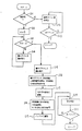
図1及び図2により、本実施例の電話装置の構成及び動作につき順次説明する。
図1は、その実施例に係る電話装置の主要部分を示す構成図で、図2はその動作を説明するためのチャートである。
まず、信号検出手段1に電話回線から着信信号が供給されると、信号検出手段1は、表示識別子が「表示可」か「表示不可」を検出する(ステップ11)。そして、「表示不可」の場合には(ステップ11→No)、通常ベル音発生手段8とスピーカ7に信号を供給して、受信者が受話器を取り上げるか着信信号が供給されなくなるまで通常の着信音を鳴らす(ステップ22→ステップ23)。
【0013】
表示識別子が「表示可」の場合には(ステップ11→Yes)、第1アドレス情報〜第9アドレス情報に格納されている発信者番号(本実施例では013−6587024、市外局番は013)の検出を行う(ステップ12、13,14)。
次に着サブアドレスに書かれている市外局番を検出する(ステップ15)。
このあと、市外局番とそれ以外に分ける番号分割手段2にて発信者番号のどこまでが市外局番か着サブアドレスかとの照合を行い、市外局番とその他の番号とに分ける(ステップ16)。市外局番、その他の番号はそれぞれ音名変換手段3により音名に変換され(ステップ17)、時間情報付与手段4にて市外局番は4分音符の長さ、その他の番号は8分音符の長さが(時間が2対1の関係)与えられる。さらに市外局番とその他の番号の間に4分休符を入れる。そして、着信音1フレーズの長さがそれを構成する音の最小単位長さの倍数となるよう最後の番号のあとに休符を入れる(ステップ18)。そして、市外局番を表す音列、休符、市外局番を除く番号を表す音列、休符の順でバッファ5に蓄積し(ステップ19)、着信音発生手段6によりその記憶した順番で各音列を呼び出してスピーカ7を介して音を発生し(ステップ20)、これに気づいた受信者がオフフックすることになる(ステップ21)。
【0014】
更に、前述の時間情報付与手段4の詳細な動作につき、図3のフローチャートを用いて説明する。
ここでは市外局番部を4分音符の長さ(300msec)、それ以外の番号部を8分音符の長さ(150msec)に割り当てられているものとする.市外局番及びそれ以外の番号が入力されると(ステップ24)、市外局番及びそれ以外の番号に対応する音名に、それぞれ4分音符、8分音符を与える(ステップ25)。次に市外局番とそれ以外の番号との間に市外局番と同じ長さの休符(4分休符=300msecの無音)を入れる(ステップ26)。全体の長さを計算して(ステップ27)、1フレーズが収まり良くまとまるように、音符の最小単位の偶数であれば4分休符を入れ(ステップ30)、奇数であれば8分休符を最後に入れる(ステップ29)。本実施例の場合、4分休符と8分休符とを入れることにより、4/4拍子となるよな聴感上収まりの良いフレーズにする。
【0015】
また、更に前述の音名変換手段3は、例えば、図4に示すように発信者電話番号の各番号を示すアドレス情報に対応させて音名が定義されているテーブルを具備し、番号「0」を示すアドレス情報「0000」に対して音名「ド」(図中、「ド1」と表示)が対応しており、以下、順に、番号「1,2,3・・・,9」に対して音名「レ(図中、レ1),ミ(図中、ミ1),ファ,・・・,(1オクターブ上の)ミ(図中、ミ2)」が対応している。
【0016】
また、図5は本実施例013−6587024の場合の着信音データである。上段nは音の送出順番であり,その順で、音名が示す音の高さで、示された時間の分だけ音が鳴り着信音1フレーズが完成する。バッファ5には1フレーズの着信音が音のデータとして蓄積され、着信音発生手段6では、前記のアドレス情報に対応した音名に基いて例えば周知の構成による予め用意された音源等から前記時間情報に対応してメロディを発生させ、スピーカ7より鳴らすものである。受信者が受話器を取り上げるか着信信号が供給されなくなるまで繰り返しバッファ5を再生する。
図6は本実施例013−6587024の着信音を楽譜で示した。この例は時間情報付与手段において、1フレーズが構成する音の最小単位長さの奇数倍であることから最後に8分休符を入れているが、偶数倍である場合たとえば02−43815796では図7のように最後は4分休符となる。
【0017】
このように着信音を2つのメロディで構成することにより、どの地域からのだれかを識別することができる。識別の方法として例えば市外局番部を無視して(聞かないで)、短いメロディで発信者を特定できるだろうし(市外局番以外が全く同じ番号である友人が多くいるとは考えにくいため)、あるいは市外局番で田舎に住む祖父母かもしれない、との予想ができる。また発信番号が異なると着信音も必然的に変わるので、単にリズミカルなフレーズを楽しみながら電話に出る、ということもできる。これは電話装置製造時に番号に対応させた音を登録しておくだけで良いので、ユーザがあらかじめメロディ等を作成する必要はなく、また、相手毎にメロディを登録しておく必要はない。
なお、前述の市外局番の登録において、携帯電話等の発信番号を示す[090]や[0120]も市外局番と同等に扱うようにしても良く、その場合には地域別の区別と同様に設置電話機からの発信か携帯電話等からの発信かの区別ができるようになる。
【0018】
【発明の効果】
本発明の電話装置は、発信電話番号に対応した着信音のメロディを自動的に作成しているので、あらかじめ発信者ごとにメロディを登録するなどの面倒な操作を必要とせずに、着信音だけで発信者を識別することができる。また、発信電話番号ごとに異なる着信音となるため、すべての発信者に対して異なる着信音を鳴らすことができる。着信音は市外局番と後に続く番号とをリズムを変えるなどして区別された2つのメロディが鳴るので、容易に発信者を識別することができる。
そして、このような電話装置ではユーザにも予想できないユニークなメロディの着信音が鳴ることもあり、遊び感覚で利用することもできる。さらに、携帯電話等に使用した場合には、着信音がユニークなので、人の多い公共の場所でも、電話がかかってきたときに、すぐに自分宛の電話であることが分かるという効果がある。
【図面の簡単な説明】
【図1】本発明の電話装置の一実施例の主要部分を示す構成図である。
【図2】本実施例に係る電話装置の動作を説明するためのフローチャート図である。
【図3】音名変換手段3のフローチャート図である。
【図4】音名変換手段3内のテーブルの構成例を示す説明図である。
【図5】バッファ内の構成例を示す説明図である。
【図6】着信音の例を示す楽譜である。
【図7】着信音の他の例を示す楽譜である。
【符号の説明】
1 信号検出手段
2 番号分割手段
3 音名変換手段
4 時間情報付与手段
5 バッファ
6 着信音発生手段
7 スピーカ
8 ベル音発生手段[0001]
BACKGROUND OF THE INVENTION
The present invention relates to a telephone device, and more particularly to a telephone device that identifies a caller by a ring tone.
[0002]
[Prior art]
Conventionally, in order to distinguish from the ringtones of other people's telephone devices in public places etc. in mobile phones etc., several types of ringtone patterns are built in beforehand, and the user selects and puts the favorite pattern Therefore, it can be used separately from other people. There is also a telephone device that incorporates a plurality of melody patterns and can combine several of them to create your own original ringtone.
[0003]
Recently, outgoing telephone number display services have become widespread. In this method, the telephone number on the calling side is displayed on the telephone device on the called side to notify the user on the called side. And as an application service using this outgoing phone number display service, by registering the name and melody in advance corresponding to the caller phone number and the phone number in the telephone device, the name is displayed at the time of incoming call, A specific ringtone can be played.
[0004]
Then, the applicant of the present application stores a pitch name corresponding to a telephone number as previously disclosed in Japanese Patent Laid-Open No. 10-233822, and stores a sequence of pitch names corresponding to the caller telephone number. An invention that is extremely convenient for the receiver side to be generated as a ringtone is made.
[0005]
[Problems to be solved by the invention]
However, in the above-described invention, it is necessary to memorize a melody made up of ten sounds, and an apparatus that can more easily identify a sender is desired.
Therefore, the present invention distinguishes the area code from the number that follows and provides two types of melodies as elements for identifying the caller, thereby making it easy to identify the caller. The purpose is to provide.
[0006]
[Means for Solving the Problems]
The telephone device of the present invention comprises the following means 1) and 2) in order to solve the above problems.
That is,
[0007]
[Means for Solving the Problems]
The telephone device of the present invention comprises the following means 1) and 2) in order to solve the above problems.
That is,
1) It is possible to receive a destination subaddress adopted in the ISDN communication method, and a name corresponding to a telephone number is stored in a storage means prepared in advance, and corresponds to a caller telephone number supplied together with an incoming signal. A telephone device that generates a string of pitch names as a ring tone,
A signal detecting means for detecting a caller telephone number supplied together with an incoming signal from a telephone line and a calling party's area code written as the called subaddress;
Division means for comparing the area code and the caller telephone number and dividing the area code and other telephone numbers;
Pitch name conversion means for converting the caller telephone number detected by the signal detection means into pitch name information;
Time information giving means for determining the pitch time based on the telephone number supplied from the dividing means;
A buffer that stores the pitch name information converted by the pitch name converting means and the time information determined by the time information giving means as sound data;
A ring tone generating means for generating a melody based on the pitch name information and time information which are the sound data stored in the buffer;
A telephone device comprising a speaker for outputting a melody output from the ring tone generating means as a voice.
[0008]
2) the time information providing means is configured to determine the time of occurrence of sound names corresponding to the area code and other numbers, rests during sound string representing the sound column and city in code that represents the area code And a rest is placed after the last number so that the length of one phrase of the ringtone is an even multiple of the minimum unit length of the sound that it constitutes. The telephone device described.
[0009]
DETAILED DESCRIPTION OF THE INVENTION
The preferred embodiments of the telephone device according to the present invention will be described below.
The telephone device of the present embodiment uses a calling telephone number display service by the ISDN communication method. Each of the
[0010]
The ISDN communication method includes a called subaddress as an information element in a call signal, and the PHS terminal device can call a mobile phone to be connected using this.
This telephone device pays attention to this destination subaddress, stores its area code in advance in storage means (not shown) through an input means ( not shown) , and writes and sends these telephone numbers to the destination subaddress at the time of transmission. That's what you do.
[0011]
The incoming signal corresponding to the calling telephone number display service includes information called a calling number parameter. In this calling number parameter, the display identifier in which “00” indicating “display possible” or “01” indicating “not displayable” is set in the calling number parameter, and the caller telephone number is 4-bit data respectively. And 10 pieces of address information represented by.
[0012]
With reference to FIGS. 1 and 2, the configuration and operation of the telephone device of this embodiment will be described in sequence.
FIG. 1 is a block diagram showing the main part of the telephone device according to the embodiment, and FIG. 2 is a chart for explaining the operation thereof.
First, when an incoming signal is supplied from the telephone line to the signal detecting means 1, the signal detecting means 1 detects whether the display identifier is “displayable” or “not displayable” (step 11). If “not displayable” (step 11 → No), a signal is supplied to the normal bell sound generation means 8 and the
[0013]
When the display identifier is “display possible” (step 11 → Yes), the caller number stored in the first address information to the ninth address information (013-6588704 in this embodiment, the area code is 013) Is detected (steps 12, 13, and 14).
Next, the area code written in the destination subaddress is detected (step 15).
Thereafter, the area code and the number dividing means 2 that divides the number are collated with the area code or the destination subaddress to divide the area code into other area codes and other numbers (step 16). The area code and other numbers are converted to pitch names by the pitch name conversion means 3 (step 17), the time code is given by the time
[0014]
Further, the detailed operation of the time
Here, the area code is assigned to the length of a quarter note (300 msec), and the other numbers are assigned to the length of an eighth note (150 msec). When the area code and other numbers are input (step 24), quarter notes and eighth notes are given to the note names corresponding to the area code and other numbers, respectively (step 25). Next, a rest having the same length as the area code (quarter rest = 300 msec of silence) is entered between the area code and the other numbers (step 26). The total length is calculated (step 27), so that a single phrase fits and is well organized, a 4-minute rest is inserted if it is the smallest unit of the note (step 30), and an 8-minute rest if it is an odd number. (Step 29). In the case of the present embodiment, by putting a 4-minute rest and an 8-minute rest, it is possible to make a phrase that fits in the sense of hearing and has a 4/4 time signature.
[0015]
Further, the above-described pitch name conversion means 3 includes a table in which a pitch name is defined in association with address information indicating each number of the caller telephone number as shown in FIG. Corresponds to the address information “0000” indicating “”, and the numbers “1, 2, 3,..., 9” are sequentially assigned. Corresponds to the note names “Re (in the figure, 1), Mi (in the figure, 1), Fa,... (1 octave above), Mi (in the figure, 2)”. .
[0016]
FIG. 5 shows ringtone data in the case of the present embodiment 013-6588704. The upper n is the order of sound transmission, and in that order, the sound is played for the indicated time at the pitch of the sound indicated by the pitch name, and one ringing tone phrase is completed. In the
FIG. 6 shows the ringtone of the present embodiment 013-65887024 as a musical score. In this example, in the time information giving means, an eighth rest is put at the end because it is an odd multiple of the minimum unit length of the sound that one phrase constitutes, but in the case of an even multiple, for example in 02-43815796 As in 7, the rest is a rest for 4 minutes.
[0017]
In this way, by configuring the ringtone with two melodies, it is possible to identify who from which region. As an identification method, for example, you can ignore the area code (don't ask) and identify the caller with a short melody (because it is difficult to think that there are many friends who have the same number except for the area code). Or you can expect that it may be a grandparent who lives in the countryside with an area code. Also, if the calling number is different, the ringtone will inevitably change, so you can simply answer the call while enjoying a rhythmic phrase. Since it is only necessary to register a sound corresponding to the number when the telephone device is manufactured, it is not necessary for the user to create a melody or the like in advance, and it is not necessary to register a melody for each partner.
In addition, in the registration of the above area code, [090] and [0120] indicating the calling number of a mobile phone or the like may be handled in the same way as the area code, and in that case, it is the same as the distinction by region. In addition, it is possible to distinguish between outgoing calls from installed telephones and outgoing calls from mobile phones.
[0018]
【The invention's effect】
The telephone device of the present invention automatically creates a ringtone melody corresponding to the calling telephone number, so that only the ringtone is required without requiring a cumbersome operation such as registering the melody for each caller in advance. The caller can be identified. Also, since different ring tones are generated for each calling telephone number, different ring tones can be generated for all callers. As the ringing tone, two melodies that are distinguished by changing the rhythm of the area code and the number that follows are ringed, so that the caller can be easily identified.
In such a telephone device, a ringtone of a unique melody that cannot be predicted by the user may sound, and can be used as if it were a play. Furthermore, when used for a mobile phone or the like, since the ringtone is unique, there is an effect that when a call is received even in a public place where there are many people, it is immediately known that the call is addressed to itself.
[Brief description of the drawings]
FIG. 1 is a configuration diagram showing main parts of an embodiment of a telephone device of the present invention.
FIG. 2 is a flowchart for explaining the operation of the telephone device according to the embodiment.
FIG. 3 is a flowchart of the pitch name conversion means 3;
FIG. 4 is an explanatory diagram showing a configuration example of a table in the pitch name conversion means 3;
FIG. 5 is an explanatory diagram illustrating a configuration example in a buffer;
FIG. 6 is a musical score showing an example of a ringtone.
FIG. 7 is a musical score showing another example of a ring tone.
[Explanation of symbols]
DESCRIPTION OF
Claims (2)
電話回線より着信信号と共に供給された発信者電話番号と前記着サブアドレスとして書き込まれた発呼側の市外局番とを検出する信号検出手段と、
前記市外局番と前記発信者電話番号とから番号比較して市外局番とそれ以外の電話番号とに分ける分割手段と、
前記信号検出手段にて検出された発信者電話番号を音名情報に変換する音名変換手段と、
前記分割手段から供給される電話番号に基づいて音名時間を決定する時間情報付与手段と、
前記音名変換手段にて変換された音名情報と前記時間情報付与手段にて決定された時間情報を音のデータとして蓄積するバッファと、
このバッファに蓄積されている前記音のデータである音名情報と時間情報をもとにメロディを発生させる着信音発生手段と、
この着信音発生手段から出力されるメロディを音声として出力するスピーカとを有することを特徴とする電話装置。It is possible to receive a destination subaddress adopted in the ISDN communication method, and a pitch name corresponding to a telephone number is stored in a storage means prepared in advance, and a pitch name corresponding to a caller telephone number supplied together with an incoming signal is stored. A telephone device that generates a ringtone as a ring tone,
A signal detecting means for detecting a caller telephone number supplied together with an incoming signal from a telephone line and a calling party's area code written as the called subaddress;
Division means for comparing the area code and the caller telephone number and dividing the area code and other telephone numbers;
Pitch name conversion means for converting the caller telephone number detected by the signal detection means into pitch name information;
Time information giving means for determining the pitch time based on the telephone number supplied from the dividing means;
A buffer that stores the pitch name information converted by the pitch name converting means and the time information determined by the time information giving means as sound data;
A ring tone generating means for generating a melody based on the pitch name information and time information which are the sound data stored in the buffer;
A telephone device comprising a speaker for outputting a melody output from the ring tone generating means as a voice.
Priority Applications (1)
| Application Number | Priority Date | Filing Date | Title |
|---|---|---|---|
| JP21853099A JP3769989B2 (en) | 1999-08-02 | 1999-08-02 | Telephone equipment |
Applications Claiming Priority (1)
| Application Number | Priority Date | Filing Date | Title |
|---|---|---|---|
| JP21853099A JP3769989B2 (en) | 1999-08-02 | 1999-08-02 | Telephone equipment |
Publications (2)
| Publication Number | Publication Date |
|---|---|
| JP2001045105A JP2001045105A (en) | 2001-02-16 |
| JP3769989B2 true JP3769989B2 (en) | 2006-04-26 |
Family
ID=16721380
Family Applications (1)
| Application Number | Title | Priority Date | Filing Date |
|---|---|---|---|
| JP21853099A Expired - Fee Related JP3769989B2 (en) | 1999-08-02 | 1999-08-02 | Telephone equipment |
Country Status (1)
| Country | Link |
|---|---|
| JP (1) | JP3769989B2 (en) |
Families Citing this family (1)
| Publication number | Priority date | Publication date | Assignee | Title |
|---|---|---|---|---|
| WO2003081572A1 (en) * | 2002-03-25 | 2003-10-02 | Yoshihiko Sano | Representation generation method, representation generation device, and representation generation system |
-
1999
- 1999-08-02 JP JP21853099A patent/JP3769989B2/en not_active Expired - Fee Related
Also Published As
| Publication number | Publication date |
|---|---|
| JP2001045105A (en) | 2001-02-16 |
Similar Documents
| Publication | Publication Date | Title |
|---|---|---|
| JP4727346B2 (en) | Ringtone adjusted on the device | |
| JP3132494B2 (en) | Ringtone generation information terminal | |
| JP2003051864A (en) | Wireless mobile terminal | |
| JP3501215B2 (en) | Mobile terminal | |
| JP3769989B2 (en) | Telephone equipment | |
| JP3748177B2 (en) | Telephone equipment | |
| KR20010099454A (en) | Voice bell sound service for the sellular phone using the text letters (user defined),sender number and number list in the handset. | |
| JP3587047B2 (en) | Incoming call notification device | |
| JP3997374B2 (en) | Telephone and recording medium | |
| JPH0918550A (en) | Terminal equipment for mobile communication with changeable ringing tone | |
| JPH10233822A (en) | Telephone set | |
| JP3479252B2 (en) | Portable wireless telephone and sound conversion method | |
| US7844047B1 (en) | Tune master internet protocol device | |
| KR20020070814A (en) | Portable terminal device and effect applying method thereof and recording medium | |
| JP3814036B2 (en) | Telephone device with ring tone switching function | |
| JP4269475B2 (en) | Mobile phone and musical sound generation control method | |
| JP3240000B1 (en) | Communication terminal device, ring tone playing method and information storage medium | |
| JP3665505B2 (en) | Cordless phone | |
| JP2000324228A (en) | Portable telephone set | |
| KR100953631B1 (en) | Mobile communication terminal and Method for setting receiving sound therein | |
| KR100596890B1 (en) | method for admitting call using admit level group | |
| JP3477099B2 (en) | Telephone equipment | |
| KR20020061800A (en) | Bell sound setting method of mobile communication terminal | |
| JP2002152363A (en) | Incoming sound generating device | |
| JPS62227246A (en) | Ringing method for ring tone of telephone set |
Legal Events
| Date | Code | Title | Description |
|---|---|---|---|
| A977 | Report on retrieval |
Free format text: JAPANESE INTERMEDIATE CODE: A971007 Effective date: 20040701 |
|
| A131 | Notification of reasons for refusal |
Free format text: JAPANESE INTERMEDIATE CODE: A131 Effective date: 20040723 |
|
| A521 | Written amendment |
Free format text: JAPANESE INTERMEDIATE CODE: A523 Effective date: 20040921 |
|
| A131 | Notification of reasons for refusal |
Free format text: JAPANESE INTERMEDIATE CODE: A131 Effective date: 20041130 |
|
| A521 | Written amendment |
Free format text: JAPANESE INTERMEDIATE CODE: A523 Effective date: 20050125 |
|
| A131 | Notification of reasons for refusal |
Free format text: JAPANESE INTERMEDIATE CODE: A131 Effective date: 20050415 |
|
| A521 | Written amendment |
Free format text: JAPANESE INTERMEDIATE CODE: A523 Effective date: 20050613 |
|
| A131 | Notification of reasons for refusal |
Free format text: JAPANESE INTERMEDIATE CODE: A131 Effective date: 20051115 |
|
| A521 | Written amendment |
Free format text: JAPANESE INTERMEDIATE CODE: A523 Effective date: 20051212 |
|
| TRDD | Decision of grant or rejection written | ||
| A01 | Written decision to grant a patent or to grant a registration (utility model) |
Free format text: JAPANESE INTERMEDIATE CODE: A01 Effective date: 20060117 |
|
| A61 | First payment of annual fees (during grant procedure) |
Free format text: JAPANESE INTERMEDIATE CODE: A61 Effective date: 20060130 |
|
| FPAY | Renewal fee payment (event date is renewal date of database) |
Free format text: PAYMENT UNTIL: 20090217 Year of fee payment: 3 |
|
| FPAY | Renewal fee payment (event date is renewal date of database) |
Free format text: PAYMENT UNTIL: 20100217 Year of fee payment: 4 |
|
| FPAY | Renewal fee payment (event date is renewal date of database) |
Free format text: PAYMENT UNTIL: 20110217 Year of fee payment: 5 |
|
| FPAY | Renewal fee payment (event date is renewal date of database) |
Free format text: PAYMENT UNTIL: 20120217 Year of fee payment: 6 |
|
| S111 | Request for change of ownership or part of ownership |
Free format text: JAPANESE INTERMEDIATE CODE: R313111 |
|
| FPAY | Renewal fee payment (event date is renewal date of database) |
Free format text: PAYMENT UNTIL: 20120217 Year of fee payment: 6 |
|
| R350 | Written notification of registration of transfer |
Free format text: JAPANESE INTERMEDIATE CODE: R350 |
|
| FPAY | Renewal fee payment (event date is renewal date of database) |
Free format text: PAYMENT UNTIL: 20120217 Year of fee payment: 6 |
|
| FPAY | Renewal fee payment (event date is renewal date of database) |
Free format text: PAYMENT UNTIL: 20130217 Year of fee payment: 7 |
|
| FPAY | Renewal fee payment (event date is renewal date of database) |
Free format text: PAYMENT UNTIL: 20130217 Year of fee payment: 7 |
|
| FPAY | Renewal fee payment (event date is renewal date of database) |
Free format text: PAYMENT UNTIL: 20140217 Year of fee payment: 8 |
|
| LAPS | Cancellation because of no payment of annual fees |