JP3769438B2 - Simple roof hut assembly - Google Patents
Simple roof hut assembly Download PDFInfo
- Publication number
- JP3769438B2 JP3769438B2 JP2000021214A JP2000021214A JP3769438B2 JP 3769438 B2 JP3769438 B2 JP 3769438B2 JP 2000021214 A JP2000021214 A JP 2000021214A JP 2000021214 A JP2000021214 A JP 2000021214A JP 3769438 B2 JP3769438 B2 JP 3769438B2
- Authority
- JP
- Japan
- Prior art keywords
- front frame
- frame
- side frame
- fixed
- screw member
- Prior art date
- Legal status (The legal status is an assumption and is not a legal conclusion. Google has not performed a legal analysis and makes no representation as to the accuracy of the status listed.)
- Expired - Fee Related
Links
Images


Landscapes
- Roof Covering Using Slabs Or Stiff Sheets (AREA)
Description
【0001】
【発明の属する技術分野】
本発明は、テラス、バルコニー屋根等の簡易屋根の小屋組に関し、特に前枠が左右の側枠に支持される構造の簡易屋根の小屋組に関する。
【0002】
【従来の技術】
従来、この種の簡易屋根の小屋組では、側枠と前枠の接合部分にブラケットを渡し、ブラケットの一方の片と側枠とをボルトにより締結すると共に、他方の片と前枠とをボルトにより締結することで(例えば実開平6−20644号公報)、前枠が左右の側枠に支持固定されている。
【0003】
【発明が解決しようとする課題】
このような従来の簡易屋根の小屋組では、組み上げられた左右の側枠に対して前枠を組み付ける場合、ブラケットを取り付けた前枠を水平に保持し、且つ左右の側枠に押し当てた状態で、ボルト止めの作業を行う必要がある。このため、前枠の組付作業を2人の作業者で行わざるを得ず、結局、他の部分は1人の作業者で間に合う場合でも、全体として2人の組付作業者を必要とする問題があった。
【0004】
本発明は、前枠の両側枠への組付作業を1人の作業者で簡単に行うことができる簡易屋根の小屋組を提供することをその目的としている。
【0005】
【課題を解決するための手段】
本発明の簡易屋根の小屋組は、梁間方向に架設した左右一対の側枠と、一対の側枠の先端部間に支持固定される前枠とを備えた簡易屋根の小屋組において、各側枠と前枠との接合部分に位置して前枠および側枠のいずれか一方に固定されると共に掛止め孔を形成したブラケットと、前枠および側枠の他方に固定されると共に前枠を側枠に当てがった状態で掛止め孔に掛止めされるねじ部材とを備え、掛止め孔は、ねじ部材の頭部が挿通可能な挿通孔部と、挿通孔部に連なりねじ部材の頭部が挿通不能な掛止め孔部とを有し、掛止め孔部にねじ部材が掛止めされた状態で、前枠は正規の固定位置から離れて各側枠にぶら下がった状態となることを特徴とする。
【0006】
この構成によれば、側枠に対し前枠を水平に保持し、前枠および側枠の一方に固定したブラケットの挿通孔部に、他方に固定したねじ部材の頭部を挿通した後、前枠を下動させることにより、ねじ部材がブラケットの掛止め孔部に移動して、前枠がブラケットに掛け止め状態となる。これにより、両側枠に前枠を片側ずつ掛け止めすることができ、またこの状態で前枠を片側ずつ両側枠に固定することができる。
【0007】
この場合、前枠と側枠とは、前枠の端部内側面を側枠の小口端に押し当てた正規の固定位置において、相互の凹凸部により前枠の上側への移動が阻止され下側への移動が許容される状態で接合され、且つねじ部材は、その頭部が側枠に対し前枠を固定位置より低い掛止め位置で挿通可能となるように配設され、掛止め孔には、挿通孔部から上側に連なり、前枠を掛止め位置から固定位置に移動したときにねじ部材が逃げる逃げ孔部が形成され、逃げ孔部は、挿通孔部を挟んで掛止め孔部と上下対称形状に形成されていることが、好ましい。
【0008】
この構成によれば、ねじ部材は、その頭部が側枠に対し前枠を固定位置より低い掛止め位置で挿通可能となるように配設されているため、前枠の組付け作業において、前枠および側枠の相互の凸部同士が当たって、ねじ部材が挿通孔部に挿通不能となる状態を極力回避することができ、掛け止めの作業性を向上させることができる。また、固定位置での前枠の側枠への固定の際に、逃げ孔部によりねじ部材を逃がすことができる。さらに、逃げ孔部と掛止め孔部と上下対称形状に形成しているため、ブラケットを左右兼用とすることができると共に、両孔部の加工性を向上させることができる。
【0009】
【発明の実施の形態】
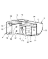
以下、添付の図面に基いて、本発明の一実施形態に係る簡易屋根の小屋組をテラスに適用した場合について説明する。図1の外観図に示すように、このテラス1は、外壁Wに固定された後部の垂木掛け2と、垂木掛け2に平行に架設した前部の前枠3と、垂木掛け2および前枠3の外端部間に掛け渡した左右一対の側枠4,4と、一対の側枠4,4間において垂木掛け2および前枠3間に等間隔に掛け渡した複数本の垂木5と、側枠4および垂木5に沿ってその上側に設けた屋根葺き材押え6とで、その主構造部が構成されており、両側枠4,4の前部で左右の支柱7,7の上端に支持固定されている。
【0010】
また、前枠3および垂木掛け2と、隣接する側枠4および垂木5とで区画され前後方向に長い領域には、アクリル板などの樹脂で構成された屋根葺き材8が、屋根葺き材押え6で押さえられるようにして、それぞれ取り付けられている。なお、前枠3は雨樋を兼ねており、図中の符号9は、テラス1の降雨を前枠3を介して地表に導く縦樋である。
【0011】
次に、図2の斜視図および図3の分解斜視図を参照して、側枠4と前枠3との接合部分の構造について説明する。側枠4と前枠3とは、側枠4の小口端に前枠3の端部内面を押し当てた状態で、相互の内部間に渡した専用ブラケット(図示せず)により接合され、これにより前枠3が左右の側枠4,4に支持固定されている。また、側枠4と前枠3のコーナー部分の外側には、前枠3の小口端に装着されるようにして、コーナーキャップ10が装着されている。さらに、側枠と前枠のコーナー部分の内側には、後述するL字ブラケット11および掛止ねじ(ねじ部材)12が配設されている。
【0012】
各側枠4は、中空部を有するアルミニウムの形材で構成され、上端面に屋根葺き材押え6がねじ止めされている。また、側枠4の上端面に形成した段部と屋根葺き材押え6との間には、屋根葺き材(両図では省略されている)8を装着するための側枠側呑込み溝14が形成されている。さらに、この側枠側呑込み溝14に面して、側枠4には下シール部材が装着される下シール装着部15が、また屋根葺き材押え6には上シール部材が装着される上シール装着部16が、それぞれ形成されている。
【0013】
一方、側枠4の前端部には、その内壁に切欠き部17が形成され、この切欠き部17から上記のL字ブラケット11が前枠3側に突出すると共に、L字ブラケット11を押さえるように前枠3の後部が嵌合している。すなわち、L字ブラケット11は、側枠側片部11aが側枠4の内壁の内部側に添接した状態で、2本の固定ねじ18,18により内壁19に固定され、切欠き部17から突出した前枠側片部11bが前枠3の後壁26に添接されている。また、この切欠き部17により側枠4に対し前枠3は、上側への移動を規制されるようにして位置決めされる。
【0014】
前枠3は、アルミニウムの形材により、中空部を有する前枠本体21と前枠本体21の前側に連なる雨樋部22とで、一体に形成されている。前枠本体21には、その中空部の上側に屋根葺き材8を装着するための前枠側呑込み溝23が形成され、前枠側呑込み溝23を構成する上端片24には上シール部材が装着される上シール装着部25が形成されている。図示では省略しているが、前枠3の後壁26には、上シール装着部26に対峙する下シール装着部を形成したシール保持部材が、ねじ止めされるようになっている。また、後壁26の下端部には、側枠3の前端部や垂木5の前端部が載置される載置片27が延設されている。なお、掛止ねじ12は、この後壁26の上部に螺合している。
【0015】
L字ブラケット11は、左右の側枠4,4に前枠3を仮置きするためのものであり(固定は上記の専用ブラケットによる)、スチール板やステンレス板などを「L」字状に折り曲げて形成されている。L字ブラケット11の一方の側枠側片部11aには、上記の固定ねじ18が螺合する上下一対のねじ孔31,31が形成され、他方の前枠側片部11bには、上記の掛止ねじ12が掛け止めされる掛止め孔32が形成されている。
【0016】
掛止め孔32は、上下の中間部に掛止ねじ12の頭部12aが挿通可能な挿通孔部32aと、挿通孔部32aから下側に連なり掛止ねじ12の頭部12aが挿通不能な掛止め孔部32bと、挿通孔部32aから上側に連なる逃げ孔部32cとで構成されている。また、逃げ孔部32cは、挿通孔部32aを挟んで掛止め孔部32bと上下対称形状に形成されている。そして、挿通孔部32aは円形に形成され、掛止ねじ12の頭部12aより充分に太径に形成されている。掛止め孔部32bおよび逃げ孔部32cはいわゆる長孔であり、その端部は掛止ねじ12の頭部12aより細径であって、胴部12bより幾分太径に形成されている。
【0017】
すなわち、前枠3に固定(螺合)した掛止ねじ12は、挿通孔部32aからその頭部12aが挿入され、この状態で掛止め孔部32bに移動(下動)させることで、抜け止め状態(掛止め状態)となる。また、図2に示すように、側枠4に前枠3を固定すべく位置合わせした状態では、掛止ねじ12が逃げ孔部32cに移動(上動)する(詳細は後述する)。なお、実施形態では、掛止め孔部32bと逃げ孔部32cとを上下対称形状とすることで、L字ブラケット11が左右兼用となるようにしている。
【0018】
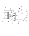
図4は、側枠4に前枠3を掛け止めする状態を示している。両側枠4,4に前枠3を取り付ける場合には、前枠3をほぼ水平に保持して片側ずつ掛け止めした後、片側ずつ本固定を行うが、掛止め作業においては、同図に示すように、掛止ねじ12をL字ブラケット11の挿通孔部32aに挿通する時に、本来の固定レベル位置(仮想線で図示)より低い掛止めレベル位置(実線で図示)に前枠3を保持するようにしている。すなわち、前枠3を掛止めレベル位置に保持した状態で、掛止ねじ12とL字ブラケット11の挿通孔部32aとが合致するようになっている。これにより、例えば前枠3のP1 の部分が側枠4のP2 の部分に、或いは前枠3のQ1 の部分が側枠4のQ2 の部分に当たって、掛止ねじ12の挿通作業が良好に行われなくなるのを、防止している。
【0019】
掛止ねじ12をL字ブラケット11の挿通孔部32aに挿通した後、前枠3を手から離すと、掛止ねじ12が挿通孔部32aが掛止め孔部32bに移動して、前枠3はL字ブラケット11のぶら下がるようにして掛け止めされる。さらに、前枠3を側枠4に本固定するときには、ぶら下がっている前枠3を上記の固定レベル位置まで移動させてから固定作業に移る。このとき、掛止ねじ12は、掛止め孔部32bから挿通孔部32aを通過して逃げ孔部32cに移動する(図2参照)。
【0020】
なお、掛止ねじ12は、前枠3を側枠4に本固定した後に締め付けておくことが好ましい。また、掛止ねじ12の取り付けに当たって、その突出寸法を確保すべく、掛止ねじ12を段突きねじとしてもよい。かかる場合には、本固定した後に締め付けは行わない。
【0021】
以上のように本実施形態によれば、掛止め孔32を形成したL字ブラケット11と掛止ねじ12との協働により、両側枠4,4に前枠3を取り付ける際に、本固定に先立って前枠3を両側枠4,4,に片側ずつ掛け止めしておくことができる。このため、前枠3の側枠4への組付作業を1人の作業者で行うことができる。したがって、テラス1の組立作業における作業コストを削減することができる。
【0022】
なお、上記実施形態では、側枠にブラケットを固定し前枠に掛止ねじを固定しているが、これを逆にし、側枠に掛止ねじを固定し前枠にブラケットを固定するようにしてもよい。かかる場合には、平板状のブラケットを用い、これを前枠の後面に固定すると共に、掛止ねじを支持部材に固定し、この支持部材を介して掛止ねじを側枠の前端部に固定することが、好ましい。
【0023】
【発明の効果】
以上のように本発明の簡易屋根の小屋組によれば、前枠を両側枠に片側ずつ掛け止めすることができ、この状態で前枠を片側ずつ両側枠に固定することができるので、前枠の組付作業を1人の作業者で簡単に行うことができる。したがって、簡易屋根の施工に際し、作業の安全性を損なうことなく、組立作業の効率化を図ることができる。
【図面の簡単な説明】
【図1】本発明の一実施形態に係る小屋組を備えたテラスの外観図である。
【図2】小屋組における側枠と前枠との接合部分の斜視図である。
【図3】小屋組における側枠と前枠との接合部分の分解斜視図である。
【図4】側枠に前枠を掛け止めする状態を示す側面図である。
【符号の説明】
1 テラス、3 前枠、4 側枠、11 L字ブラケット、12 掛止ねじ、12a 頭部、17 切欠き部、18 固定ねじ、21 前枠本体、26 後壁、27 載置片、32 掛止め孔、32a 挿通孔部、32b 掛止め孔部、32c 逃げ孔部[0001]
BACKGROUND OF THE INVENTION
The present invention relates to a roof set of a simple roof such as a terrace and a balcony roof, and more particularly to a roof set of a simple roof having a structure in which a front frame is supported by left and right side frames.
[0002]
[Prior art]
Conventionally, in this type of simple roof hut assembly, a bracket is passed to the joint between the side frame and the front frame, and one piece of the bracket and the side frame are fastened with bolts, and the other piece and the front frame are bolted together. (For example, Japanese Utility Model Publication No. 6-20644), the front frame is supported and fixed to the left and right side frames.
[0003]
[Problems to be solved by the invention]
In such a conventional simple roof hut assembly, when the front frame is assembled to the assembled left and right side frames, the front frame to which the brackets are attached is held horizontally and pressed against the left and right side frames. Now, it is necessary to perform bolting work. For this reason, the assembly work of the front frame must be performed by two workers, and eventually two assembly workers are required as a whole even if the other parts are in time for one worker. There was a problem to do.
[0004]
An object of the present invention is to provide a simple roof hut assembly that allows a single operator to easily perform the assembly work of the front frame to both side frames.
[0005]
[Means for Solving the Problems]
The simplified roof shed of the present invention is a simplified roof shed comprising a pair of left and right side frames erected in the direction between the beams and a front frame supported and fixed between the front ends of the pair of side frames. A bracket that is positioned at a joint portion between the frame and the front frame and is fixed to one of the front frame and the side frame and has a latch hole, and is fixed to the other of the front frame and the side frame and the front frame A screw member that is hooked into the latch hole in a state of being applied to the side frame, and the latch hole is connected to the insertion hole portion through which the head portion of the screw member can be inserted, and the screw member. head possess a through non retaining hole, in a state in which retaining holes on the threaded member is latched, the front frame be in a state of hanging away from the normal fixed position on each side frame It is characterized by.
[0006]
According to this configuration, the front frame is held horizontally with respect to the side frame, the head of the screw member fixed to the other is inserted into the insertion hole portion of the bracket fixed to one of the front frame and the side frame, By moving the frame downward, the screw member moves to the latching hole portion of the bracket, and the front frame is latched to the bracket. As a result, the front frame can be hooked to the both side frames one by one, and the front frame can be fixed to the both side frames one by one in this state.
[0007]
In this case, the front frame and the side frame are prevented from moving to the upper side of the front frame by mutual irregularities at the regular fixed position where the inner surface of the end of the front frame is pressed against the edge of the side frame. The screw member is joined in a state that allows movement to the side frame, and the screw member is disposed so that the front frame can be inserted into the side frame at a latching position lower than the fixed position. Is formed on the upper side from the insertion hole part, and a relief hole part is formed through which the screw member escapes when the front frame is moved from the latching position to the fixed position. It is preferable that it is formed in a vertically symmetrical shape.
[0008]
According to this configuration, the screw member is disposed so that its head can be inserted into the side frame at a latching position lower than the fixed position, so in the assembly work of the front frame, It is possible to avoid as much as possible the state in which the projecting portions of the front frame and the side frame come into contact with each other and the screw member cannot be inserted into the insertion hole portion, and the workability of latching can be improved. Further, when the front frame is fixed to the side frame at the fixing position, the screw member can be released by the escape hole. Furthermore, since the escape hole portion and the latch hole portion are formed in a vertically symmetrical shape, the bracket can be used for both the left and right sides, and the workability of both the hole portions can be improved.
[0009]
DETAILED DESCRIPTION OF THE INVENTION
Hereinafter, a case where a simple roof hut set according to an embodiment of the present invention is applied to a terrace will be described with reference to the accompanying drawings. As shown in the external view of FIG. 1, the terrace 1 includes a
[0010]
Further, a roofing material 8 made of resin such as an acrylic plate is provided in the front frame 3 and the
[0011]
Next, referring to the perspective view of FIG. 2 and the exploded perspective view of FIG. 3, the structure of the joint portion between the
[0012]
Each
[0013]
On the other hand, a
[0014]
The front frame 3 is integrally formed with a front frame
[0015]
The L-shaped
[0016]
The
[0017]
That is, the latching
[0018]
FIG. 4 shows a state in which the front frame 3 is hooked on the
[0019]
After inserting the latching
[0020]
The retaining
[0021]
As described above, according to the present embodiment, when the front frame 3 is attached to the both side frames 4 and 4 by the cooperation of the L-shaped
[0022]
In the above embodiment, the bracket is fixed to the side frame and the retaining screw is fixed to the front frame. However, this is reversed, and the retaining screw is fixed to the side frame and the bracket is fixed to the front frame. May be. In such a case, a flat bracket is used and fixed to the rear surface of the front frame, and the latch screw is fixed to the support member, and the latch screw is fixed to the front end portion of the side frame via the support member. It is preferable to do.
[0023]
【The invention's effect】
As described above, according to the simplified roof shed assembly of the present invention, the front frame can be hooked to both sides of the frame one by one, and in this state, the front frame can be fixed to both sides of the frame one by one. The assembly work of the frame can be easily performed by one worker. Therefore, when constructing the simple roof, it is possible to improve the efficiency of the assembly work without impairing the safety of the work.
[Brief description of the drawings]
FIG. 1 is an external view of a terrace provided with a cabin set according to an embodiment of the present invention.
FIG. 2 is a perspective view of a joint portion between a side frame and a front frame in a cabin set.
FIG. 3 is an exploded perspective view of a joint portion between a side frame and a front frame in a cabin set.
FIG. 4 is a side view showing a state in which a front frame is hooked on a side frame.
[Explanation of symbols]
1 terrace, 3 front frame, 4 side frame, 11 L-shaped bracket, 12 retaining screw, 12a head, 17 notch, 18 fixing screw, 21 front frame body, 26 rear wall, 27 mounting piece, 32 hanging Stop hole, 32a insertion hole, 32b hook hole, 32c escape hole
Claims (2)
前記各側枠と前記前枠との接合部分に位置して当該前枠および当該側枠のいずれか一方に固定されると共に掛止め孔を形成したブラケットと、
前記前枠および前記側枠の他方に固定されると共に当該前枠を当該側枠に当てがった状態で前記掛止め孔に掛止めされるねじ部材とを備え、
前記掛止め孔は、前記ねじ部材の頭部が挿通可能な挿通孔部と、当該挿通孔部に連なり前記ねじ部材の頭部が挿通不能な掛止め孔部とを有し、
前記掛止め孔部に前記ねじ部材が掛止めされた状態で、前記前枠は正規の固定位置から離れて前記各側枠にぶら下がった状態となることを特徴とする簡易屋根の小屋組。In the roof set of a simple roof provided with a pair of left and right side frames erected in the direction between the beams, and a front frame supported and fixed between the front ends of the pair of side frames,
A bracket which is positioned at a joint portion between each side frame and the front frame and is fixed to either the front frame or the side frame and has a latch hole;
The front frame is fixed to the other of the front frame and the side frame and a screw member which is latched in the latch hole in a state in which wanted applied to the side frame,
The retaining holes, possess the head can be inserted a through hole portion of the screw member, the head of the screw member contiguous to the insertion hole portion is a through non retaining hole,
A simple roof hut assembly , wherein the front frame is in a state of being hung from each side frame away from a normal fixing position in a state in which the screw member is hooked in the hooking hole .
且つ前記ねじ部材は、その頭部が前記側枠に対し前記前枠を前記固定位置より低い掛止め位置で挿通可能となるように配設され、
前記掛止め孔には、前記挿通孔部から上側に連なり、前記前枠を前記掛止め位置から前記固定位置に移動したときに前記ねじ部材が逃げる逃げ孔部が形成され、 前記逃げ孔部は、前記挿通孔部を挟んで前記掛止め孔部と上下対称形状に形成されていることを特徴とする請求項1に記載の簡易屋根の小屋組。Wherein the front frame and the side frame, in a fixed position of the normal pressed against the end portion side of the front frame to the fore end of the side frame, upward movement of the front frame due to irregularities of the mutually blocking Are joined in a state that allows downward movement,
And the screw member is arranged so that its head can be inserted into the side frame at the latching position lower than the fixed position,
The retaining hole is connected to the upper side from the insertion hole portion, and a relief hole portion is formed in which the screw member escapes when the front frame is moved from the latching position to the fixed position. 2. The simple roof shed assembly according to claim 1, wherein the roof is formed in a vertically symmetrical shape with respect to the retaining hole portion with the insertion hole portion interposed therebetween.
Priority Applications (1)
| Application Number | Priority Date | Filing Date | Title |
|---|---|---|---|
| JP2000021214A JP3769438B2 (en) | 2000-01-31 | 2000-01-31 | Simple roof hut assembly |
Applications Claiming Priority (1)
| Application Number | Priority Date | Filing Date | Title |
|---|---|---|---|
| JP2000021214A JP3769438B2 (en) | 2000-01-31 | 2000-01-31 | Simple roof hut assembly |
Publications (3)
| Publication Number | Publication Date |
|---|---|
| JP2001207579A JP2001207579A (en) | 2001-08-03 |
| JP2001207579A5 JP2001207579A5 (en) | 2004-10-07 |
| JP3769438B2 true JP3769438B2 (en) | 2006-04-26 |
Family
ID=18547659
Family Applications (1)
| Application Number | Title | Priority Date | Filing Date |
|---|---|---|---|
| JP2000021214A Expired - Fee Related JP3769438B2 (en) | 2000-01-31 | 2000-01-31 | Simple roof hut assembly |
Country Status (1)
| Country | Link |
|---|---|
| JP (1) | JP3769438B2 (en) |
-
2000
- 2000-01-31 JP JP2000021214A patent/JP3769438B2/en not_active Expired - Fee Related
Also Published As
| Publication number | Publication date |
|---|---|
| JP2001207579A (en) | 2001-08-03 |
Similar Documents
| Publication | Publication Date | Title |
|---|---|---|
| JP3769438B2 (en) | Simple roof hut assembly | |
| JP4528658B2 (en) | Surface lattice fixture and surface lattice unit including the same | |
| JP5236345B2 (en) | Building dredge equipment | |
| JP5998363B2 (en) | Roof structure | |
| JP3189146B2 (en) | Connection structure of rafter and front frame | |
| JP3238848B2 (en) | Window shutter support structure | |
| JP3632512B2 (en) | Installation method of air conditioner outdoor unit | |
| JPH0225904Y2 (en) | ||
| JP2769677B2 (en) | Structures such as terraces and balconies | |
| JPS5841318Y2 (en) | Mounting structure of the lower end of the handrail | |
| JP5758651B2 (en) | Projection support structure | |
| JP3657182B2 (en) | bay window | |
| JPS6317813Y2 (en) | ||
| JPH0142596Y2 (en) | ||
| JP3467462B2 (en) | Handrail device | |
| JP5988354B2 (en) | Roof body mounting method and roof structure | |
| JPH08232409A (en) | Transverse roofing plate and envelope thereof | |
| JP3308658B2 (en) | Parapet installation structure | |
| JP2003041660A (en) | Simplified roof | |
| JP2821617B2 (en) | Roof panel support at Alcove | |
| JP2000303641A (en) | Main-pole fixing member of awning for building | |
| JPS5844162Y2 (en) | Girder mounting structure | |
| JP4166740B2 (en) | Balcony joisting mounting structure | |
| JPS5924747Y2 (en) | Connecting structure of handrail and clothesline post | |
| JP2562884Y2 (en) | Kasagi panel mounting structure |
Legal Events
| Date | Code | Title | Description |
|---|---|---|---|
| A977 | Report on retrieval |
Free format text: JAPANESE INTERMEDIATE CODE: A971007 Effective date: 20050811 |
|
| A131 | Notification of reasons for refusal |
Free format text: JAPANESE INTERMEDIATE CODE: A131 Effective date: 20050823 |
|
| A521 | Written amendment |
Free format text: JAPANESE INTERMEDIATE CODE: A523 Effective date: 20051017 |
|
| TRDD | Decision of grant or rejection written | ||
| A01 | Written decision to grant a patent or to grant a registration (utility model) |
Free format text: JAPANESE INTERMEDIATE CODE: A01 Effective date: 20060131 |
|
| A61 | First payment of annual fees (during grant procedure) |
Free format text: JAPANESE INTERMEDIATE CODE: A61 Effective date: 20060206 |
|
| R150 | Certificate of patent or registration of utility model |
Ref document number: 3769438 Country of ref document: JP Free format text: JAPANESE INTERMEDIATE CODE: R150 Free format text: JAPANESE INTERMEDIATE CODE: R150 |
|
| FPAY | Renewal fee payment (event date is renewal date of database) |
Free format text: PAYMENT UNTIL: 20090210 Year of fee payment: 3 |
|
| FPAY | Renewal fee payment (event date is renewal date of database) |
Free format text: PAYMENT UNTIL: 20100210 Year of fee payment: 4 |
|
| FPAY | Renewal fee payment (event date is renewal date of database) |
Free format text: PAYMENT UNTIL: 20110210 Year of fee payment: 5 |
|
| FPAY | Renewal fee payment (event date is renewal date of database) |
Free format text: PAYMENT UNTIL: 20120210 Year of fee payment: 6 |
|
| FPAY | Renewal fee payment (event date is renewal date of database) |
Free format text: PAYMENT UNTIL: 20130210 Year of fee payment: 7 |
|
| FPAY | Renewal fee payment (event date is renewal date of database) |
Free format text: PAYMENT UNTIL: 20140210 Year of fee payment: 8 |
|
| LAPS | Cancellation because of no payment of annual fees |