JP3769002B2 - Paper transfer device for image forming apparatus - Google Patents
Paper transfer device for image forming apparatus Download PDFInfo
- Publication number
- JP3769002B2 JP3769002B2 JP2004334201A JP2004334201A JP3769002B2 JP 3769002 B2 JP3769002 B2 JP 3769002B2 JP 2004334201 A JP2004334201 A JP 2004334201A JP 2004334201 A JP2004334201 A JP 2004334201A JP 3769002 B2 JP3769002 B2 JP 3769002B2
- Authority
- JP
- Japan
- Prior art keywords
- roller
- image forming
- idle gear
- forming apparatus
- reverse
- Prior art date
- Legal status (The legal status is an assumption and is not a legal conclusion. Google has not performed a legal analysis and makes no representation as to the accuracy of the status listed.)
- Expired - Fee Related
Links
- 230000002093 peripheral effect Effects 0.000 claims description 3
- 238000010586 diagram Methods 0.000 description 6
- 230000002265 prevention Effects 0.000 description 3
- 238000005299 abrasion Methods 0.000 description 2
- 229920001971 elastomer Polymers 0.000 description 2
- 230000007257 malfunction Effects 0.000 description 2
- 239000000463 material Substances 0.000 description 2
- 229920002943 EPDM rubber Polymers 0.000 description 1
- JOYRKODLDBILNP-UHFFFAOYSA-N Ethyl urethane Chemical compound CCOC(N)=O JOYRKODLDBILNP-UHFFFAOYSA-N 0.000 description 1
- 230000005540 biological transmission Effects 0.000 description 1
- 230000006835 compression Effects 0.000 description 1
- 238000007906 compression Methods 0.000 description 1
- 238000001514 detection method Methods 0.000 description 1
- 238000012986 modification Methods 0.000 description 1
- 230000004048 modification Effects 0.000 description 1
- 229910052710 silicon Inorganic materials 0.000 description 1
- 239000010703 silicon Substances 0.000 description 1
Images


Classifications
-
- B—PERFORMING OPERATIONS; TRANSPORTING
- B41—PRINTING; LINING MACHINES; TYPEWRITERS; STAMPS
- B41J—TYPEWRITERS; SELECTIVE PRINTING MECHANISMS, i.e. MECHANISMS PRINTING OTHERWISE THAN FROM A FORME; CORRECTION OF TYPOGRAPHICAL ERRORS
- B41J13/00—Devices or arrangements of selective printing mechanisms, e.g. ink-jet printers or thermal printers, specially adapted for supporting or handling copy material in short lengths, e.g. sheets
- B41J13/02—Rollers
- B41J13/025—Special roller holding or lifting means, e.g. for temporarily raising one roller of a pair of nipping rollers for inserting printing material
-
- B—PERFORMING OPERATIONS; TRANSPORTING
- B65—CONVEYING; PACKING; STORING; HANDLING THIN OR FILAMENTARY MATERIAL
- B65H—HANDLING THIN OR FILAMENTARY MATERIAL, e.g. SHEETS, WEBS, CABLES
- B65H5/00—Feeding articles separated from piles; Feeding articles to machines
- B65H5/06—Feeding articles separated from piles; Feeding articles to machines by rollers or balls, e.g. between rollers
-
- B—PERFORMING OPERATIONS; TRANSPORTING
- B41—PRINTING; LINING MACHINES; TYPEWRITERS; STAMPS
- B41J—TYPEWRITERS; SELECTIVE PRINTING MECHANISMS, i.e. MECHANISMS PRINTING OTHERWISE THAN FROM A FORME; CORRECTION OF TYPOGRAPHICAL ERRORS
- B41J11/00—Devices or arrangements of selective printing mechanisms, e.g. ink-jet printers or thermal printers, for supporting or handling copy material in sheet or web form
- B41J11/02—Platens
- B41J11/14—Platen-shift mechanisms; Driving gear therefor
-
- B—PERFORMING OPERATIONS; TRANSPORTING
- B41—PRINTING; LINING MACHINES; TYPEWRITERS; STAMPS
- B41J—TYPEWRITERS; SELECTIVE PRINTING MECHANISMS, i.e. MECHANISMS PRINTING OTHERWISE THAN FROM A FORME; CORRECTION OF TYPOGRAPHICAL ERRORS
- B41J29/00—Details of, or accessories for, typewriters or selective printing mechanisms not otherwise provided for
- B41J29/38—Drives, motors, controls or automatic cut-off devices for the entire printing mechanism
-
- B—PERFORMING OPERATIONS; TRANSPORTING
- B65—CONVEYING; PACKING; STORING; HANDLING THIN OR FILAMENTARY MATERIAL
- B65H—HANDLING THIN OR FILAMENTARY MATERIAL, e.g. SHEETS, WEBS, CABLES
- B65H2404/00—Parts for transporting or guiding the handled material
- B65H2404/10—Rollers
- B65H2404/14—Roller pairs
- B65H2404/143—Roller pairs driving roller and idler roller arrangement
-
- B—PERFORMING OPERATIONS; TRANSPORTING
- B65—CONVEYING; PACKING; STORING; HANDLING THIN OR FILAMENTARY MATERIAL
- B65H—HANDLING THIN OR FILAMENTARY MATERIAL, e.g. SHEETS, WEBS, CABLES
- B65H2404/00—Parts for transporting or guiding the handled material
- B65H2404/10—Rollers
- B65H2404/14—Roller pairs
- B65H2404/144—Roller pairs with relative movement of the rollers to / from each other
- B65H2404/1441—Roller pairs with relative movement of the rollers to / from each other involving controlled actuator
-
- B—PERFORMING OPERATIONS; TRANSPORTING
- B65—CONVEYING; PACKING; STORING; HANDLING THIN OR FILAMENTARY MATERIAL
- B65H—HANDLING THIN OR FILAMENTARY MATERIAL, e.g. SHEETS, WEBS, CABLES
- B65H2601/00—Problem to be solved or advantage achieved
- B65H2601/10—Ensuring correct operation
- B65H2601/12—Compensating; Taking-up
- B65H2601/121—Wear
Landscapes
- Engineering & Computer Science (AREA)
- Mechanical Engineering (AREA)
- Sheets, Magazines, And Separation Thereof (AREA)
Description
本発明は,画像形成装置の用紙移送装置に関し,詳細にはピックアップされた用紙の重送を防止できるように,移送ローラと接触した状態で正回転または逆回転する逆転ローラを有する,画像形成装置の用紙移送装置に関する。 The present invention relates to a sheet transfer device of an image forming apparatus, and in particular, an image forming apparatus having a reverse rotation roller that rotates forward or backward in contact with a transfer roller so as to prevent double feeding of picked up sheets. The present invention relates to a paper transport apparatus.
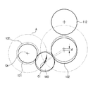
一般に,電子写真方式の画像形成装置1は,ノックアッププレート方式の給紙装置2により用紙Pが供給される。用紙Pは,図1に示すように,ピックアップローラ3によりピックアップされるが,ピックアップされた用紙Pの重送を防止するため,一対のローラからなる用紙移送装置10が備えられる。
In general, the electrophotographic
用紙移送装置10は,図2に示すように,移送ローラ11及び逆転ローラ12から構成されるが,逆転ローラ12には同軸上にトルクリミッタ13が装着され,逆転ローラ12を逆回転させることのできる逆転モータ(図示せず)が,移送ローラ11を駆動する駆動装置と個別的に設けられる。
As shown in FIG. 2, the
逆転ローラ12は,移送ローラ11と反対方向に回転し,用紙Pが重送されると,その摩擦力の差により重送された用紙移送を防止する。用紙Pが重送されない場合には,移送ローラ11との摩擦力が逆転ローラ12と同軸上に接続されて,一定サイズのトルクを有するトルクリミッタ13のトルクより大きくなるので,逆転ローラ12は,移送ローラ11と同一方向に回転する。逆転ローラ12には,逆転モータの動力を伝達する逆転ギア14が同軸に設置されるが,逆転ギア14は,トルクリミッタ13と共に反対方向に回転し,移送ローラ11と個別に動く。
The
上記のように構成された従来の技術に係る移送ローラ11及び逆転ローラ12は,表面が一定の摩擦係数を有するゴム材質からなる。該当ゴムは,NR,NBR,EPDM,ウレタン,シリコンなど一定硬度,摩擦係数および耐久性などを有した材質を用途に応じて用いる。
The
ところが,逆転ローラ12は,用紙進入方向と逆方向に回転するため,その表面の摩耗が激しい。このような摩耗によって移送ローラシャフトS1と,逆転ローラシャフトS2とは,逆転ローラ12の摩耗が進行されるにしたがい,最初の平行状態を維持できず,図2に示しているように,次第に傾斜した状態に変わる。
However, since the
これは,逆転ギア14の位置が固定されているためである。このように,移送ローラシャフトS1と逆転ローラシャフトS2とが平行とならない場合,移送ローラ11と逆転ローラ12との間の接触が円滑にならないことにより,逆転ローラ12及び移送ローラ11が用紙重送防止機能及び用紙移送機能を行うことができなくなって,画像装置の誤作動を誘発させてしまうことがある。
This is because the position of the
そこで,本発明はこのような問題に鑑みてなされたもので,その目的とするところは,逆転ローラが移送ローラに接触した状態で正回転及び逆回転することにより摩耗した場合に,重送防止性能の低下することを防止できる,画像形成装置の用紙移送装置を提供することである。 Accordingly, the present invention has been made in view of such problems, and the object of the present invention is to prevent double feed when the reverse rotation roller is worn by forward and reverse rotation in contact with the transfer roller. It is an object of the present invention to provide a sheet transfer device for an image forming apparatus that can prevent a decrease in performance.
上記課題を解決するために,本発明のある観点によれば,用紙を移送する移送ローラと,移送ローラに接触して配設される逆転ローラと,逆転ローラに動力を提供する駆動モータと,逆転ローラと駆動モータとを連結し,動力を伝達するアイドルギアと,を含み,アイドルギアは,逆転ローラの摩耗に応じて回転中心が移動しながら,駆動モータの動力を逆転ローラに伝達することを特徴とする画像形成装置の用紙移送装置が提供される。 In order to solve the above-described problems, according to one aspect of the present invention, a transfer roller for transferring a sheet, a reverse roller disposed in contact with the transfer roller, a drive motor for providing power to the reverse roller, An idle gear that couples the reverse rotation roller and the drive motor to transmit power, and the idle gear transmits the power of the drive motor to the reverse rotation roller while the rotation center moves in accordance with wear of the reverse rotation roller. A sheet transport device for an image forming apparatus is provided.
つまり,移送ローラと逆転ローラとは,互いに接触された状態で正回転および逆回転しながら,用紙を画像形成部に移送し,用紙の重送を防止する役割をする。この場合,逆転ローラは,移送ローラと遊離された別の動力源である駆動モータにより動力を伝達されるが,動力伝達のためにアイドルギアを含むギア列が用いられる。この場合,アイドルギアは,逆転ローラの摩耗発生時に,常に前記移送ローラと逆転ローラとが一定の接触力を維持できるように,その回転中心が移動するように構成される。 In other words, the transfer roller and the reverse roller serve to prevent the double feeding of the paper by transferring the paper to the image forming unit while rotating forward and backward while being in contact with each other. In this case, the reverse rotation roller is transmitted with power by a drive motor which is a separate power source separated from the transfer roller, but a gear train including an idle gear is used for power transmission. In this case, the idle gear is configured such that the center of rotation thereof moves so that the transfer roller and the reverse rotation roller can always maintain a constant contact force when the reverse rotation roller is worn.
こうして,逆転ローラに摩耗が発生して移送ローラと逆転ローラとの間の中心軸間の距離が変化しても,逆転ローラに動力を伝達するアイドルギアが移動しながら,回転中心が変化した距離に対応するように移動して,移送ローラ及び逆転ローラのシャフトの平行状態を保ち,逆転ローラと移送ローラとが一定の接触力を維持できる。 Thus, even if the reverse roller is worn and the distance between the central axes of the transfer roller and the reverse roller changes, the distance at which the rotation center changes while the idle gear that transmits power to the reverse roller moves. The shafts of the transfer roller and the reverse rotation roller are kept parallel, and the reverse rotation roller and the transfer roller can maintain a constant contact force.
この時,アイドルギアは,駆動モータの駆動ギアの中心を中心として,アイドルギアの中心との距離を半径とする仮想の円に重なる軌跡上を移動することが望ましい。そのために,アイドルギアは,アイドルギアの移動軌跡と対応して画像形成装置の一側に形成されたスイングスロットに沿って中心軸がスイングするように構成することができる。 At this time, it is desirable that the idle gear moves on a trajectory that overlaps a virtual circle having a radius from the center of the idle gear with the center of the drive gear of the drive motor as the center. Therefore, the idle gear can be configured such that the central axis swings along a swing slot formed on one side of the image forming apparatus corresponding to the movement track of the idle gear.
アイドルギアを移動させるためのスイングスロットは,例えば,内周面の曲率が,アイドルギアの移動軌跡と平行するように形成することができ,これにより,逆転ローラのシャフトの位置が移動する場合にも,逆転ギアとアイドルギアとの噛み合いを維持することができる。 The swing slot for moving the idle gear can be formed, for example, so that the curvature of the inner peripheral surface is parallel to the movement locus of the idle gear, and this causes the shaft position of the reverse rotation roller to move. However, the meshing of the reverse gear and the idle gear can be maintained.
また,アイドルギアを移動させるためのスイングスロットとして,駆動モータの駆動ギアの中心を中心として,アイドルギアの中心との距離を半径とする仮想の円の接線方向に形成することもできる。この時のスイングスロットは,アイドルギアの中心軸を弾性支持する弾性部材を含むことが好ましい。弾性部材は,アイドルギアの中心軸を加圧し,逆転ギア側への弾性復原力を作用させて,逆転ギアとアイドルギアとの噛み合った状態を維持できるようにする。 In addition, the swing slot for moving the idle gear can be formed in the tangential direction of a virtual circle centered on the center of the drive gear of the drive motor and having a radius from the center of the idle gear. The swing slot at this time preferably includes an elastic member that elastically supports the central axis of the idle gear. The elastic member pressurizes the central axis of the idle gear and applies an elastic restoring force to the reverse gear side so that the meshed state of the reverse gear and the idle gear can be maintained.
以上のような本発明に係る画像形成装置の用紙移送装置によれば,逆転ローラに摩耗が発生して移送ローラと逆転ローラとの間の中心軸間の距離が変化しても,逆転ローラに動力を伝達するアイドルギアが,回転中心が変化した距離に対応するように移動して,逆転ローラと移送ローラとが一定の接触力を維持できるため,重送防止性能を保ち,製品の信頼性を確保することができる。 According to the sheet transfer device of the image forming apparatus according to the present invention as described above, even if the reverse roller is worn and the distance between the central axes between the transfer roller and the reverse roller changes, The idle gear that transmits power moves so as to correspond to the distance that the center of rotation has changed, and the reverse rotation roller and the transfer roller can maintain a constant contact force, thus maintaining double feed prevention performance and product reliability. Can be secured.
以下に添付図面を参照しながら,本発明の好適な実施の形態について詳細に説明する。なお,本明細書及び図面において,実質的に同一の機能構成を有する構成要素については,同一の符号を付することにより重複説明を省略する。 Hereinafter, preferred embodiments of the present invention will be described in detail with reference to the accompanying drawings. In the present specification and drawings, components having substantially the same functional configuration are denoted by the same reference numerals, and redundant description is omitted.
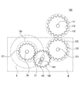
図3は,本発明の好適な実施の形態に係る画像形成装置の用紙移送装置の動作状態を示した説明図である。図面に示すように,本実施の形態に係る画像形成装置の用紙移送装置100は,移送ローラ110と逆転ローラ120とが相互一定圧力で対向されるように配設される。移送ローラ110及び逆転ローラ120の各々は,互いに別々の駆動源により動力を伝達される移送ギア112及び逆転ギア122を備える。逆転ローラ120は,駆動モータ130(図4参照)から動力が伝達されて回転する。
FIG. 3 is an explanatory diagram showing an operation state of the sheet transport device of the image forming apparatus according to the preferred embodiment of the present invention. As shown in the drawing, the
また,逆転ローラ120は,逆転ローラシャフト121に同軸的に設置されるトルクリミッタTを含む負荷手段を備える。トルクリミッタTは,移送ローラ110および逆転ローラ120との間に用紙が進入した際に,移送ローラ110と逆転ローラ120との間の摩擦力が一定値以下に低下したかどうかを感知する。
Further, the
トルクリミッタTの感知信号により,逆転ローラ120は,用紙が一枚ずつ供給される場合は,移送ローラ110と同じ方向に回転しながら用紙を移送し,用紙が重送された場合には,移送ローラ110と反対方向に回転しながら重送された用紙を分離して,一枚の用紙のみが画像形成部(図示せず)に進入できるようにする。
According to the detection signal of the torque limiter T, the reversing
詳細に説明すれば,給紙部でピックアップされた用紙は,互いに接触するように設置された移送ローラ110及び逆転ローラ120を通過し,画像形成部に進行する。逆転ローラ120は,移送ローラ110との摩擦力が一定値より大きく作用する場合には,移送ローラ110と同じ方向に回転し,移送ローラ110との摩擦力が小さな場合には,移送ローラ110の回転方向と反対方向に回転する。
More specifically, the sheet picked up by the sheet feeding unit passes through the
ところが,逆転ローラ120は,用紙との間に持続的に摩擦が起きるので,使用時間が増加するにしたがい,次第に磨耗量が増加する。逆転ローラ120の摩耗が進行すると,逆転ローラシャフト121の軸位置は,図3及び図4に示すように,距離dだけ移送ローラ110側に平行に移動する。
However, since the
したがって,逆転ギア122が,逆転ローラシャフト121の軸位置が移動した場合にも,駆動モータ130(図4参照)から動力を持続的に伝達されるためには,逆転ギア122の位置変化に連動して噛み合いを維持できるアイドルギア140が要求される。このようなアイドルギア140は,図4に示されたように,その中心軸Ciが移動できるように構成されなければならない。
Accordingly, in order for the
これにより,アイドルギア140の中心軸Ciは,図4に示した所定のスイング軌跡Aに沿って移動しながら,逆転ギア122とアイドルギア140との間の噛み合いを維持することができる。
Thereby, the center axis Ci of the
そして,アイドルギア140は,その中心軸Ciが画像形成装置の片側壁面W(図5および図6参照)に移動可能に設置されて,逆転ローラ120の摩耗により逆転ローラシャフト121が移送ローラ110側に移動する場合にも,中心軸Ciがスイング軌跡Aに沿って移動できるので,アイドルギア140と逆転ギア122との噛み合いが維持される。
The
スイング軌跡Aは,アイドルギア140の中心軸Ciと駆動ギア131の中心軸Cmとの間の距離を半径とする仮想の円の円周方向と重なることが好ましい。図5及び図6は,アイドルギア140の中心軸Ciがスイング軌跡Aに沿って移動することができる好ましい実施例を概略的に示した図面である。
The swing trajectory A preferably overlaps with the circumferential direction of a virtual circle whose radius is the distance between the center axis Ci of the
例えば,図5のように,アイドルギア140の中心軸Ciは,画像形成装置の片側壁面Wにスライド可能に設置される。そして,中心軸Ciが設置される壁面Wにスイング軌跡Aと重なるように,中心軸Ciの直径と対応される幅で曲線スイングスロット141が設けられる。
For example, as shown in FIG. 5, the central axis Ci of the
したがって,逆転ローラ120の摩耗により逆転ローラシャフト121の位置が移動する場合,中心軸Ciが曲線スイングスロット141に沿ってスライドすることができ,逆転ギア122とアイドルギア140との噛み合いは継続維持することができる。
Accordingly, when the position of the
曲線スイングスロット141は,図5に示すように,その幅をアイドルギア140の中心軸Ciの直径と対応するように形成することが良く,さらに,スイング軌跡Aと対応する円周曲率を有するように形成することが良い。
As shown in FIG. 5, the
また,アイドルギアがスイング軌跡Aに沿って移動することができる構造の他の実施例を,図6に示す。アイドルギア140の中心軸Ciは,画像形成装置の片側壁面Wにスライド可能に設置され,中心軸Ciが設置される壁面Wに,スイング軌跡Aの接線方向に中心軸Ciの直径と対応する幅で直線スイングスロット142が設けられる。
FIG. 6 shows another embodiment of the structure in which the idle gear can move along the swing path A. A center axis Ci of the
この場合,直線スイングスロット142の内部には,例えば,圧縮スプリングのような所定の弾性部材143を設置する。弾性部材143は,アイドルギア140に逆転ギア122側への弾性復原力を作用させて,アイドルギア140が逆転ギア122と噛み合った状態を維持できるようにする。
In this case, a predetermined
上記のような画像形成装置の用紙移送装置100によれば,逆転ローラ120が摩耗する場合,逆転ローラシャフト121が逆転ローラ120の摩耗された分だけ移送ローラ110側に移動するが,アイドルギア140が逆転ギア122の位置変化に連動して噛み合いを維持するので,逆転ローラ120が片摩耗したり,移送ローラ110と離隔して用紙重送防止機能が作動しなかったりするなどの誤動作を防止することができる。
According to the
以上,添付図面を参照しながら本発明の好適な実施形態について説明したが,本発明は係る例に限定されないことは言うまでもない。当業者であれば,特許請求の範囲に記載された範疇内において,各種の変更例または修正例に想到し得ることは明らかであり,それらについても当然に本発明の技術的範囲に属するものと了解される。 As mentioned above, although preferred embodiment of this invention was described referring an accompanying drawing, it cannot be overemphasized that this invention is not limited to the example which concerns. It will be apparent to those skilled in the art that various changes and modifications can be made within the scope of the claims, and these are of course within the technical scope of the present invention. Understood.
本発明は,画像形成装置の用紙移送装置に適用可能であり,レーザプリンタ,複写機,複合機などを含む全ての画像形成装置の用紙移送装置に適用可能である。 The present invention can be applied to a paper transport device of an image forming apparatus, and can be applied to a paper transport device of all image forming apparatuses including a laser printer, a copying machine, a multifunction peripheral, and the like.
100 用紙移送装置
110 移送ローラ
111 移送ローラシャフト
112 移送ギア
120 逆転ローラ
121 逆転ローラシャフト
122 逆転ギア
130 駆動モータ
131 駆動ギア
140 アイドルギア
A スイング軌跡
Cm 中心軸
Ci 中心軸
d 距離
DESCRIPTION OF
Claims (6)
前記移送ローラに接触して配設される逆転ローラと,
前記逆転ローラに動力を提供する駆動モータと,
前記逆転ローラと前記駆動モータとを連結し,動力を伝達するアイドルギアと,
を含み,
前記アイドルギアは,前記逆転ローラの摩耗に応じて回転中心が移動しながら,前記駆動モータの動力を前記逆転ローラに伝達することを特徴とする画像形成装置の用紙移送装置。 A transfer roller for transferring paper;
A reverse rotation roller disposed in contact with the transfer roller;
A drive motor that provides power to the reverse roller;
An idle gear for connecting the reverse roller and the drive motor to transmit power;
Including
The sheet transfer device of the image forming apparatus, wherein the idle gear transmits the power of the drive motor to the reverse rotation roller while the rotation center moves in accordance with wear of the reverse rotation roller.
前記駆動モータの駆動ギアの中心を中心として,前記アイドルギアの中心との距離を半径とする仮想の円に重なる軌跡上を移動することを特徴とする請求項1に記載の画像形成装置の用紙移送装置。 The idle gear is
2. The sheet of the image forming apparatus according to claim 1, wherein the sheet moves on a trajectory overlapping a virtual circle whose radius is the distance from the center of the idle gear with the center of the drive gear of the drive motor as a center. Transfer device.
前記アイドルギアの移動軌跡と対応して画像形成装置の一側に形成されたスイングスロットに沿って中心軸がスイングすることを特徴とする請求項2に記載の画像形成装置の用紙移送装置。 The idle gear is
The sheet transporting device for an image forming apparatus according to claim 2, wherein the central axis swings along a swing slot formed on one side of the image forming apparatus corresponding to the movement path of the idle gear.
内周面の曲率が,前記アイドルギアの移動軌跡と平行するように形成されることを特徴とする請求項3に記載の画像形成装置の用紙移送装置。 The swing slot is
4. The sheet transfer device for an image forming apparatus according to claim 3, wherein a curvature of an inner peripheral surface is formed in parallel with a movement locus of the idle gear.
前記駆動モータの駆動ギアの中心を中心として,前記アイドルギアの中心との距離を半径とする仮想の円の接線方向に形成されることを特徴とする請求項3に記載の画像形成装置の用紙移送装置。 The swing slot is
The sheet of the image forming apparatus according to claim 3, wherein the sheet is formed in a tangential direction of an imaginary circle having a radius from a center of the drive gear of the drive motor as a radius. Transfer device.
前記アイドルギアの中心軸を弾性支持する弾性部材を含むことを特徴とする請求項5に記載の画像形成装置の用紙移送装置。
The swing slot is
6. The sheet transport device for an image forming apparatus according to claim 5, further comprising an elastic member that elastically supports a central axis of the idle gear.
Applications Claiming Priority (1)
| Application Number | Priority Date | Filing Date | Title |
|---|---|---|---|
| KR1020030093183A KR20050061771A (en) | 2003-12-18 | 2003-12-18 | Sheet feeding apparatus for image forming apparatus |
Publications (2)
| Publication Number | Publication Date |
|---|---|
| JP2005179057A JP2005179057A (en) | 2005-07-07 |
| JP3769002B2 true JP3769002B2 (en) | 2006-04-19 |
Family
ID=34675820
Family Applications (1)
| Application Number | Title | Priority Date | Filing Date |
|---|---|---|---|
| JP2004334201A Expired - Fee Related JP3769002B2 (en) | 2003-12-18 | 2004-11-18 | Paper transfer device for image forming apparatus |
Country Status (3)
| Country | Link |
|---|---|
| US (1) | US20050133982A1 (en) |
| JP (1) | JP3769002B2 (en) |
| KR (1) | KR20050061771A (en) |
Families Citing this family (2)
| Publication number | Priority date | Publication date | Assignee | Title |
|---|---|---|---|---|
| KR20100071194A (en) * | 2008-12-19 | 2010-06-29 | 삼성전자주식회사 | Feeding unit and image forming apparatus having the same |
| JP5939717B2 (en) * | 2014-05-19 | 2016-06-22 | 京セラドキュメントソリューションズ株式会社 | Sheet conveying apparatus and image forming apparatus having the same |
Family Cites Families (14)
| Publication number | Priority date | Publication date | Assignee | Title |
|---|---|---|---|---|
| US5172899A (en) * | 1989-04-28 | 1992-12-22 | Seikosha Co., Ltd. | Paper feeder |
| KR930003004Y1 (en) * | 1990-10-11 | 1993-05-27 | 주식회사 신도리코 | Sheet feeding apparatus |
| US5351945A (en) * | 1992-05-30 | 1994-10-04 | Mita Industrial Co., Ltd. | Overlapped transfer-preventing mechanism |
| JPH0971333A (en) * | 1995-09-06 | 1997-03-18 | Brother Ind Ltd | Paper feeding device |
| US5947465A (en) * | 1995-12-20 | 1999-09-07 | Brother Kogyo Kabushiki Kaisha | Sheet-supply device having a drive force transmission mechanism |
| JP3610149B2 (en) * | 1996-02-20 | 2005-01-12 | キヤノン株式会社 | Image forming apparatus |
| JPH1087109A (en) * | 1996-06-07 | 1998-04-07 | Canon Inc | Sheet conveying device and image formation device |
| JP3689997B2 (en) * | 1996-08-26 | 2005-08-31 | ブラザー工業株式会社 | Paper feeding device and printing device |
| JPH10129871A (en) * | 1996-10-28 | 1998-05-19 | Ricoh Co Ltd | Paper feeder |
| JPH1159941A (en) * | 1997-08-07 | 1999-03-02 | Ricoh Co Ltd | Frr feeding type sheet feeder |
| JP4568456B2 (en) * | 2000-08-21 | 2010-10-27 | 株式会社リコー | Paper feeder |
| JP3720706B2 (en) * | 2000-12-18 | 2005-11-30 | キヤノン株式会社 | Sheet feeding apparatus, image forming apparatus including the same, and image reading apparatus |
| JP3710430B2 (en) * | 2002-04-05 | 2005-10-26 | キヤノン株式会社 | Sheet material feeding apparatus and image forming apparatus |
| JP4072397B2 (en) * | 2002-08-16 | 2008-04-09 | キヤノン株式会社 | Automatic feeding apparatus and recording apparatus provided with the same |
-
2003
- 2003-12-18 KR KR1020030093183A patent/KR20050061771A/en active Search and Examination
-
2004
- 2004-07-20 US US10/893,974 patent/US20050133982A1/en not_active Abandoned
- 2004-11-18 JP JP2004334201A patent/JP3769002B2/en not_active Expired - Fee Related
Also Published As
| Publication number | Publication date |
|---|---|
| KR20050061771A (en) | 2005-06-23 |
| US20050133982A1 (en) | 2005-06-23 |
| JP2005179057A (en) | 2005-07-07 |
Similar Documents
| Publication | Publication Date | Title |
|---|---|---|
| US9162836B2 (en) | Driving force transmission device, medium transport device, image reading apparatus and image forming apparatus | |
| US9879733B2 (en) | Power transmission device and image forming apparatus including same | |
| US8556261B2 (en) | Power transmission method and apparatus, medium discharging apparatus using the same, and image forming device having the medium discharging apparatus | |
| JP4609564B2 (en) | Belt unit and image forming apparatus | |
| KR101174052B1 (en) | Paper sheet advancing device | |
| JP3769002B2 (en) | Paper transfer device for image forming apparatus | |
| JP2019151448A (en) | Separation roller, sheet feeding apparatus and image forming apparatus | |
| JPH0674311A (en) | Torque transmission and use thereof | |
| JP6045324B2 (en) | Sheet feeding apparatus and image forming apparatus | |
| JP2003292184A (en) | Sheet material feeding device and image forming device | |
| JP2003321137A (en) | Sheet feeding system, and method of dispersing abrasion | |
| US20050140082A1 (en) | Paper supply device of image forming apparatus and method | |
| JP2008037637A (en) | Image forming device | |
| JP2738576B2 (en) | Paper feeder | |
| JP3446975B2 (en) | Paper feeder | |
| KR200311184Y1 (en) | Manual Feeder for Copiers | |
| JP5234425B2 (en) | Deceleration device, image carrier driving device, and image forming apparatus | |
| JP2003237967A (en) | Sheet feeding method, sheet feeder and image forming device | |
| JP2002255387A (en) | Paper feeding and separating device | |
| JP2011190922A (en) | Drive transmission device and image forming device equipped with the same | |
| JP2003237968A (en) | Sheet feeding method, sheet feeder and image forming device | |
| JP2007091451A (en) | Image forming device | |
| JP2005226796A (en) | Rotary body drive device and image forming device | |
| KR20040057073A (en) | Mechanism to transfer paper for printer system | |
| JPH07179242A (en) | Sheet carrying device |
Legal Events
| Date | Code | Title | Description |
|---|---|---|---|
| A977 | Report on retrieval |
Free format text: JAPANESE INTERMEDIATE CODE: A971007 Effective date: 20060117 |
|
| TRDD | Decision of grant or rejection written | ||
| A01 | Written decision to grant a patent or to grant a registration (utility model) |
Free format text: JAPANESE INTERMEDIATE CODE: A01 Effective date: 20060124 |
|
| A61 | First payment of annual fees (during grant procedure) |
Free format text: JAPANESE INTERMEDIATE CODE: A61 Effective date: 20060202 |
|
| R150 | Certificate of patent or registration of utility model |
Free format text: JAPANESE INTERMEDIATE CODE: R150 |
|
| LAPS | Cancellation because of no payment of annual fees |