JP3768735B2 - Face image processing device - Google Patents
Face image processing device Download PDFInfo
- Publication number
- JP3768735B2 JP3768735B2 JP19295899A JP19295899A JP3768735B2 JP 3768735 B2 JP3768735 B2 JP 3768735B2 JP 19295899 A JP19295899 A JP 19295899A JP 19295899 A JP19295899 A JP 19295899A JP 3768735 B2 JP3768735 B2 JP 3768735B2
- Authority
- JP
- Japan
- Prior art keywords
- eye
- nostril
- candidates
- face image
- candidate
- Prior art date
- Legal status (The legal status is an assumption and is not a legal conclusion. Google has not performed a legal analysis and makes no representation as to the accuracy of the status listed.)
- Expired - Fee Related
Links
Images


Classifications
-
- G—PHYSICS
- G06—COMPUTING; CALCULATING OR COUNTING
- G06T—IMAGE DATA PROCESSING OR GENERATION, IN GENERAL
- G06T11/00—2D [Two Dimensional] image generation
-
- G—PHYSICS
- G06—COMPUTING; CALCULATING OR COUNTING
- G06V—IMAGE OR VIDEO RECOGNITION OR UNDERSTANDING
- G06V40/00—Recognition of biometric, human-related or animal-related patterns in image or video data
- G06V40/10—Human or animal bodies, e.g. vehicle occupants or pedestrians; Body parts, e.g. hands
- G06V40/16—Human faces, e.g. facial parts, sketches or expressions
- G06V40/168—Feature extraction; Face representation
- G06V40/171—Local features and components; Facial parts ; Occluding parts, e.g. glasses; Geometrical relationships
-
- G—PHYSICS
- G06—COMPUTING; CALCULATING OR COUNTING
- G06V—IMAGE OR VIDEO RECOGNITION OR UNDERSTANDING
- G06V40/00—Recognition of biometric, human-related or animal-related patterns in image or video data
- G06V40/10—Human or animal bodies, e.g. vehicle occupants or pedestrians; Body parts, e.g. hands
- G06V40/18—Eye characteristics, e.g. of the iris
- G06V40/19—Sensors therefor
-
- A—HUMAN NECESSITIES
- A61—MEDICAL OR VETERINARY SCIENCE; HYGIENE
- A61B—DIAGNOSIS; SURGERY; IDENTIFICATION
- A61B5/00—Measuring for diagnostic purposes; Identification of persons
- A61B5/117—Identification of persons
- A61B5/1171—Identification of persons based on the shapes or appearances of their bodies or parts thereof
- A61B5/1176—Recognition of faces
Description
【0001】
【発明の属する技術分野】
この発明は、入力顔画像より2次元テンプレートを用いて、より正確に鼻孔および目の抽出を行う顔画像処理装置に関するものである。
【0002】
【従来の技術】
従来の運転者のテンプレートを用いた顔画像処理装置としては、例えば特開平8−175218号公報等に記載されているものがある。この従来例の装置全体の構成は、図24のブロック図に示されている。この従来の顔画像処理装置は、運転者を撮像するカメラ12と、A/D変換器、正規化回路及び相関演算回路を備えた画像処理装置13と、標準テンプレート及び眉毛や目などの顔要素配置データが予め格納されているメモリ16と、画像処理装置13の処理結果から運転者の運転状態を判別し、警報装置15に制御信号を出力して警報を発する電子制御ユニット(ECU)14からなる。
【0003】
また、この装置の動作すなわち処理のフローは図26に示されている。図26において、ステップS101により運転者の顔画像が撮像され、得られた顔画像は、ステップS102にて、最大輝度を256、最小輝度を1とする濃淡正規化が行われる。正規化処理が行われた後、ステップS103にて標準テンプレートを用いて対象テンプレートが検出される。すなわち、図25における、撮像された画像に対して、予め設定されている標準テンプレートを用いて相関演算を行い、テンプレート作成手段M2により運転者用の対象テンプレートを作成する。
【0004】
テンプレート作成手段M2は、撮像された画像内で運転者の対象顔領域を設定する対象顔領域設定手段M5と、その対象顔領域内で1つの目及び1つの眉を含む顔の縦方向に長い対象目近傍領域を設定する対象目近傍領域設定手段M6と、その対象目近傍領域内で目を含む対象目領域を設定する対象目領域設定手段を備えており、対象顔領域及び対象目近傍領域及び対象目領域それぞれを対象テンプレートとする。対象テンプレートが検出された後、再びカメラにより運転者の顔画像が撮影され、ステップS104にて濃淡正規化が行われる。そして、この正規化顔画像に対し、ステップS105にて対象テンプレートによる相関演算にて目領域の検出が行われる。S106において、ECU14は、順次入力される目領域の画像に基づいて運転者の目の状態を判定する。そしてステップS107で運転者の目状態に異常があると判定された場合には、運転者が居眠りしていると判定して、S108にて警報装置を作動させ、運転者に注意を促す。
【0005】
【発明が解決しようとする課題】
しかしながら、画像を多値データのままで処理を行うと非常に時間がかかり、また眼鏡装着の有無や天候・髪等の付属情報によって顔の状態(眉と目の関係等)は変化し、不安定である。ところが、上記した従来の顔画像処理装置では、眉と目を含む情報量の多いテンプレートを用いて相関演算を行っているため、入力画像総てを検索するには非常に時間がかかる上、個人情報を持たない標準テンプレートにより検索を開始するため、通常とは違った付属情報の影響下における画像では、鼻孔や目の検出が不可能となる恐れがある。
【0006】
この発明は、上記のような問題点を解決するためになされたもので、情報量は少ないが鼻孔および目の特徴を的確に表した2次元テンプレートを一つ或いは複数用いることにより、付属情報に左右されることなく精度よく、高速に鼻孔および目を抽出することができる顔画像処理装置を提供することを目的とするものである。
【0007】
【課題を解決するための手段】
この発明の一側面に係る顔画像処理装置は、顔画像を入力する顔画像入力手段と、入力した顔画像より目候補が存在する領域を推定する目領域設定手段と、目領域内で目候補を複数の輝度値を有するデータに変換する目候補抽出手段と、抽出された候補内で目およびその位置を確定する目確定手段とを備え、目候補抽出手段は、予め設定されている2次元テンプレートおよび少なくとも一つの閾値を用いて、注目画素と周辺画素との相対輝度に対する簡易マッチングを行うとともに、さらに2次元テンプレートおよび少なくとも一つの閾値によって抽出される鼻孔候補もしくは目候補の数が所定値以下の場合には、注目画素との相対輝度のマッチングを行う周辺画素の数を軽減していくものである。
【0008】
この発明の他の側面に係る顔画像処理装置は、顔画像を入力する顔画像入力手段と、入力した顔画像より鼻孔候補が存在する領域を推定する鼻孔領域設定手段と、鼻孔領域内で鼻孔候補を複数の輝度値を有するデータに変換する鼻孔候補抽出手段と、抽出された鼻孔候補内で鼻孔を確定する鼻孔確定手段と、確定した鼻孔より目候補が存在する領域を推定する目領域設定手段と、目領域内で目候補を複数の輝度値を有するデータに変換する目候補抽出手段と、目候補抽出手段により抽出された候補内で目候補およびその位置を確定する目確定手段とを備え、鼻孔候補抽出手段もしくは目候補抽出手段は、予め設定されている2次元テンプレートおよび少なくとも一つの閾値を用いて、注目画素と周辺画素との相対輝度に対する簡易マッチングを行うとともに、さらに2次元テンプレートおよび少なくとも一つの閾値によって抽出される鼻孔候補もしくは目候補の数が所定値以下の場合には、注目画素との相対輝度のマッチングを行う周辺画素の数を軽減していくものである。
【0010】
この発明の1つの実施態様においては、鼻孔候補抽出手段もしくは目候補抽出手段は、さらに可変抽出輝度閾値を用いて、マッチングを行う対象を限定することを特徴とするものである。
【0011】
この発明の他の実施態様においては、鼻孔候補抽出手段もしくは目候補抽出手段は、さらに可変抽出輝度閾値または2次元テンプレートを複数用いることを特徴とするものである。
【0012】
この発明の更に他の実施態様においては、鼻孔候補抽出手段もしくは目候補抽出手段は、さらに2次元テンプレートおよび少なくとも一つの閾値によって抽出される鼻孔候補もしくは目候補の数が所定値以下の場合には、注目画素との相対輝度のマッチングを行う周辺画素の数を軽減していくことを特徴とするものである。
【0013】
【発明の実施の形態】
以下、添付図面により本発明の実施の形態について詳細に説明する。
【0014】
実施の形態1.
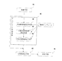
図1はこの発明の実施の形態1に係る顔画像処理装置の第1の構成例を示す。第1の構成例における顔画像処理装置は、顔画像を撮影するCCDカメラ1とCCDカメラから出力された顔画像の画像データを記憶する画像メモリ2と、画像メモリ2から画像データを読み出して、その画像データに基づいて画像処理を行うCPU3とで構成される。
【0015】
図2は図1におけるCPU3内の処理の概要を示す機能ブロック図である。図2において、CPU3は、画像メモリ2から画像データを読み出して入力する顔画像入力手段4と、顔画像入力手段4に入力された画像データに基づいて目領域を設定する目領域設定手段5と、目領域設定手段5の出力に基づいて目候補を抽出する目候補抽出手段6と、目候補抽出手段6の出力に基づいて目とその存在位置を確定する目確定手段7とを備える。これらの手段は、CPU3がプログラムを実行してソフト的に処理する内容を機能的に表したものである。
【0016】
まず、CPU3は、画像メモリ2より顔画像の画像データを読み込んで顔画像入力手段4に入力し、目領域設定手段5により入力画像内で目が存在すると思われる領域を推定し、目候補抽出手段6により輝度変換を行って目候補を抽出する。この際、輝度変換をしたデータは入力画像とは別のメモリに保存し、入力画像データも後で参照できるようにしておく。さらに、抽出された領域から、目確定手段7により目候補および目位置を確定する。以下、各手段について詳細に説明する。
【0017】
図3はCCDカメラ1により撮影された顔画像8を示した図である。入力画像内で目候補が存在すると思われる領域を推定する目領域設定手段5では、例えば目検索モード中は図8に示すような顔全体をカバーする比較的大きな矩形の目検索領域5rを設定し、また目追跡モード中は目のみをカバーする比較的小さな矩形の目追跡領域5rl、5rrを設定する。目検索モードとは目位置学習が未だ行われていない(未だ目を見つけていない)状態を指し、目追跡モードとは目学習済の(目を見つけた)状態を指す。検索領域5rは画面内で通常の運転姿勢で顔が入る範囲に限定して設定される。追跡領域5rl、5rrは、目学習位置(又は目前回位置)5gl、5grから所定幅の領域を設定する。ここでは、両目に対し目領域を設定したが、左右どちらか一方でも構わない。
【0018】
次に、目候補抽出手段6について説明する。図4のフローチャートに示すように、ステップS1において、目候補抽出手段6は、予め用意した目形状を簡単かつ的確に表した2次元テンプレート6t(例えば図5の(a)参照)を用いて、目領域内で簡易マッチングを行い、目候補と思われる要素を抽出する(図5の(b))。目候補抽出手段6では、目領域設定手段5により設定した領域内で、注目画素6cをX、Y方向に順次移動させ、注目画素6cの周辺画素のうち目判定要素画素(=2次元テンプレートで指し示す点)の条件を確認し、注目画素6cが目候補画素であるかどうかの判定を行う。
【0019】
判定基準は、条件A(注目画素に対し、目判定要素画素総ての輝度値が所定閾値6th以上であること)である。
【0020】
図6に示した注目点(網掛け画素)の輝度値に対し、目判定要素画素(白画素)総ての輝度値が+6thを上回れば(図4でYES:実線)、注目点は目候補画素であると判定し(図6断面図)、ステップS2において、注目点の画素すなわち注目画素を輝度値1に設定し、また、ステップS1での判定結果が「NO」(図4で破線)(目判定要素画素総ての輝度値が+6th以下)であれば、ステップS3で注目画素を輝度値0に設定する。次いで、ステップS4において、全画素について検索済みか否かを判定し、「NO」であれば次の画素に移り、「YES」(実線)であれば処理を終了する(図6において、斜線画素=周辺画素、黒画素=目候補画素)。ここで目が抽出でき、眉が抽出されにくい理由は、図7に示すように、眉上部には髪、下部には目があり、また眉の形状から目形状の2次元テンプレートでは、眉は条件Aを総て満たすのが困難であるためである。
【0021】
次に、目確定手段7により上記で抽出した領域中の目候補および目位置を確定する。目候補抽出手段6によって抽出された領域に対し、図8の(b)に示すように、各X座標ごとにそのY軸上に存在する黒画素数を数えてその数値をX軸に投影し、所定幅7w・所定高さ7hを持つものを帯状領域として認め、さらにその帯状領域内の各Y座標ごとにそのX軸上に存在する黒画素数を数えてその数値をY軸に投影し、所定幅7w'・所定高さ7h'を持つものを目候補領域とする。目候補領域推定後にラベリングを行い、目候補を確定する。但し、通常のラベリングでは、図10の(b)に示すように、各画素につき8方のラベル確認と、全画素がラベル済みになるまでのループを要するため時間がかかる。そこで、図10の(a)に示すように、7方のラベル確認と1ループでの処理に限定し、ラベリングを簡単化して行う。図9にラベリングのフローチャートを示す。図9において、(a)は本発明のラベリング処理フロー、(b)は通常(従来)のラベリング処理フローである。
【0022】
次に、本発明によるラベリング処理について、図9(a)により説明する。
(1)2値化後の画像の所定領域に対し、例えば領域の左上部より注目画素を順次移動し、まず注目画素が黒色画素であるか判定する(ステップST1)。黒色画素であれば、ラベル済みであるかを判定し(ステップST2)、ラベル済みでなければ新しいラベル番号(NO.R)をふる(ステップST3)。
【0023】
(2)その後、ラベル開始位置(=現在位置)を記憶し(ステップST4)、図10(a)に示すように、ラベル開始位置より走査方向に順次走査する。すなわち、全画素検索済みか判定し(ステップST5)、NOであれば次の画素へ進み(ステップST6)、黒色画素か判定(ステップST7)する。走査中は注目画素の周辺7画素のラベル状態を判定する。注目画素が黒色画素であり(ステップST7でYES)、かつ周辺7画素にラベル済みのものが有れば(ステップST8でYES)、注目画素にラベル番号(NO.R)をふる(ステップST9)。(このとき新しいラベル番号(NO)になることはない。)それ以外はラベルをふらない。すなわち、周囲7画素中1画素がラベル済みであれば、その時点で注目画素にラベルをふり、次の画素へ進む。
【0024】
(3)検索領域終了まで行ったら(すなわち全画素検索済みになったら(ステップST5でYES))、ラベル開始位置へ戻り(ステップST10)、ラベル番号(NO.R)を更新(インクリメント)し(ステップST11)、全画素検索済みか判定し(ステップST12)、検索済みでなければ(NO)、次の画素へ進み(ステップST13)、ステップST1に戻って前記走査を繰り返す。
【0025】
(4)検索領域内すべての点に対し、(1)〜(3)の走査がすめば(ステップST12でYES)、処理を終了する(ステップST14)。
【0026】
これに対して、通常の(すなわち従来より知られている)動作は、図9(b)に示す通りである。すなわち、
(A)2値化後の画像の所定領域に対し、例えば領域の左上部より注目画素を順次移動し、まず注目画素が黒色画素であるかを判定する(ステップST21)。黒色画素であれば、ラベル済みであるかどうかを判定し(ステップST22)、ラベル済みでなければ新しいラベル番号(NO.R)をふる(ステップST23)。ステップST21で黒色画素でないか、或いはステップST22でラベル済みと判定されれば、全画素検索済みであるか(ステップST34)、および黒色画素が全てラベル済みであるかを判定し(ステップST35)、全画素検索済みでないか、或いは全画素がラベル済みでなければ次の画素へ進んで(ステップST37)、再びステップST21へ戻る。
【0027】
(B)ステップST23の後、図10(b)に示すように、注目画素の周囲8画素を確認し(ステップST24)、ラベル済みでなければ、次の周辺画素へ移り(ステップST25)、これが黒色画素であるかを判定し(ステップST26)、黒画素で有れば、注目画素と同じラベル番号(NO.R)を各周辺画素にふり、ラベル数RCTをカウントする(ステップST27)。
【0028】
(C)次いで(B)(ステップST24乃至27)を走査方向に順次行い、ステップST24で周囲8画素がラベル済みとなったら、全画素検索済みか判定し(ステップST28)、この判定結果がNOで有れば、次の画素へ進んで(ステップST29)、ラベル済みかを判定し(ステップST30)、ラベル済みで有ればステップST24へ進み、ラベル済みでなければステップST28へ進む。このようにして、ラベルすべきものがなくなるまで前記走査を繰り返す。
【0029】
(D)このようにして(C)まで終了すれば、すなわちステップST28で全画素検索済みになれば、領域開始位置へ戻り(ステップST31)、ラベル数RCTカウントが零であるかを判定し(ステップST32)、零でなければステップST30へ進み、零で有ればラベル番号(NO.R)を更新(インクリメント)し(ステップST33)、(A)〜(C)を繰り返す。
【0030】
(E)検索領域内すべての黒色画素に対し、(A)〜(D)の走査が済めば、すなわちステップST35で全黒色画素ラベル済みに達したら、処理を終了する(ステップST38)。
【0031】
さらに上記ラベリング処理においてラベル中にそのX・Y方向重心位置を演算し、目位置とする。但し、ラベルされた候補のX・Y方向幅や面積などから目とは判定できない場合には目未検出とし、もしくは要素が2つ以上ある場合などは要素のX・Y方向幅や面積などから最も目らしいもの1候補を抽出し、その重心を目位置とする。図11の(a)乃至(c)には、このような3つの例が示されている。(a)は目が1つの連続した領域で表される場合を示しており、目領域が「1」として連続的にラベリングされており、(b)は反射等で目が数個に分断された場合を示しており、この例では3つに分断された連続領域がそれぞれ「1」、「2」、「3」としてラベリングされており、また(c)は目が一部分分断された場合を示しており、2つに分離された領域がそれぞれ「1」、「2」で示されている。(b)及び(c)では、「2」とトラベルされた領域が目候補として抽出される。
【0032】
また、目確定手段7により確定した目位置はメモリ内に保存し、目追跡モード時の目領域設定に用いる。
【0033】
図12乃至16は本発明の実施の形態1に関連した第2の構成例を示すものである。第2の構成例は、図12に示すように、第1の構成例(図2参照)に、鼻孔領域設定手段9、鼻孔候補抽出手段10および鼻孔確定手段11を追加し、それと同時に目領域設定手段5を変更したものである。
【0034】
先ず、入力画像内で鼻孔候補が存在すると思われる領域を推定する鼻孔領域設定手段9について述べる。鼻孔領域設定手段9では、例えば鼻孔検索モード中には、図15に示すように、目から顎までを含む比較的大きな矩形の鼻孔検索領域9r、鼻孔追跡モード中には鼻のみを含む比較的小さな矩形の鼻孔追跡領域9rrをそれぞれ設定する。ここで、鼻孔検索モードとは、鼻孔位置学習が未(すなわち未だ鼻孔を目を見つけていない状態)を指し、鼻孔追跡モードとは、鼻孔学習済の状態を指す。鼻孔検索領域9rは画面内で通常の運転姿勢で顔が入る範囲に限定して設定する。また、鼻孔追跡領域9rrは、鼻孔学習位置(又は、鼻孔前回位置)9grから所定幅の領域を設定する。
【0035】
鼻孔候補抽出手段10は、例えば図13の(a)に示すような2次元テンプレート10tで鼻孔領域内で簡易マッチングを行い、図13の(b)に示すような鼻孔候補と思われる要素を抽出する。具体的には、鼻孔候補抽出手段10では、図14の(a)に示すように、鼻孔領域設定手段9により設定した領域内で、注目画素10cをX、Y方向に順次移動させ、注目画素10cの周辺画素のうち鼻孔判定要素画素(=2次元テンプレートで指し示す点)の条件を確認し、注目画素10cが鼻孔候補画素であるかどうかの判定を行う。判定基準は条件A(注目画素に対し、鼻孔判定要素画素総ての輝度値が所定閾値10th以上であること)である。図14の(a)の断面図である図14の(b)に示すように、注目点(網掛け画素)10cの輝度値に対し、鼻孔判定要素画素(白画素)総ての輝度値が+10thを上まわれば、注目点は鼻孔候補画素であると判定し、次の画素に移る。図14の(a)及び(b)において、斜線画素=周辺画素、黒画素=目候補画素である。
【0036】
次に、鼻孔確定手段11により上記のように抽出した領域中の鼻孔候補および鼻孔位置を確定する。鼻孔候補抽出手段10によって抽出された領域に対してラベリングを行い、鼻孔候補を確定する。ラベリングは上記第1の構成例と同様に行う。
【0037】
さらに、上記ラベリング処理におけるラベル付け中に抽出領域のX・Y方向重心位置を演算し、鼻孔候補位置とする。鼻孔候補は、図16に示すように、顔横方向に大きさと形状(楕円に近いもの)の近いものが2つ並ぶものを検索し、鼻孔とする。鼻孔位置は2つの候補の中点とする。ラベル付けされた要素のX・Y方向幅や面積などから鼻孔とは判定できない場合には鼻孔未検出とし、もしくは候補が2つ以上ある場合などは候補のX・Y方向幅や面積などから最も鼻孔らしいもの1候補を抽出し、その重心中点を鼻孔位置とする。
【0038】
鼻孔確定手段11により確定した鼻孔位置はメモリ内に保存し、鼻孔追跡モード時の鼻孔領域設定に用いる。
【0039】
図17および18は本発明の実施の形態1に関連した第3の構成例を示すものである。第3の構成例は、上記第1、第2の構成例の鼻孔候補抽出手段10および目候補抽出手段6において、可変抽出輝度閾値を用いるものである。
【0040】
具体的には、図17のフローチャートに示すように、図1のステップS1と同様のテンプレートの条件を判定するステップS1の前に、ステップS6で、上記第1、第2の構成例の鼻孔候補抽出手段10および目候補抽出手段6において、注目画素の輝度値を可変抽出輝度閾値(鼻孔と目はそれぞれ違う閾値)により評価し、2次元テンプレートによる評価を行うか否かを判定する。判定基準は、図18に示すように、条件B(注目画素の輝度値が、可変抽出輝度閾値610th以下であること)である。ここで、注目点画素を減少させることにより、処理速度がより早くなる。また可変抽出輝度閾値610thは、前画面までの2次元テンプレート通過画素の輝度値により可変に制御することで、固定値にした場合よりさらに画像に適した値を得ることが可能である。
【0041】
可変抽出輝度閾値は、例えば、推定閾値を設定し、目(或いは鼻孔)を検索後、抽出可であれば閾値が適当であるとして、その閾値を継続して用いる。抽出不可であれば推定閾値は不適当すなわち目(或いは鼻孔)画素が範囲外として閾値を段階的に緩めていく。また、抽出可の際の閾値は前述のように継続しても良いが、2次元テンプレート通過画素の平均輝度値または最大輝度値などを利用して再設定すると、より適当な閾値が得られる。
【0042】
図19および20は本発明の実施の形態1に関連した第4の構成例を示すものである。第4の構成例は、上記第1、第2、第3の構成例の鼻孔候補抽出手段10および目候補抽出手段6において、2次元テンプレートを複数用いるものである。
【0043】
上記第1、第2、第3の構成例では、鼻孔候補抽出手段10および目候補抽出手段6において2次元テンプレート6t、9tを使用したが、図19に示すように、ステップS1で、最初の2次元テンプレート6t、9tが条件Aを満たさない場合には、ステップS7において、次の2次元テンプレート6t'、9t'がその条件Aを満たしているか否かを判定し、満たせば通過画素とするものである。
【0044】
また、複数テンプレートには色々考えられるが、例えば図20(A)では、注目画素とテンプレート画素の距離が変わるだけであるが、(3)及び(4)に示すように、左側のテンプレートだけでは眼鏡フレームなどの位置によっては、注目点と目下側テンプレートの距離が長いために通過不可((3)参照)である可能性があり、また(1)及び(2)に示すように、右側のテンプレートだけでは眉と目の間隔が狭い人では通過不可((2)参照)になる可能性がある。
【0045】
すなわち、図20(B)のように、テンプレートと注目点との距離やテンプレートの大きさの大小で個人差をカバーすることが可能である。ここでは、テンプレートと注目点との距離の異なる2つ目のテンプレート(1)、(2)及び大きさの異なる2つの鼻孔のテンプレート(3)、(4)を示しているが、これらはどちらにも言えることで、目のテンプレートを大小2種類にすることでの個人差をカバーしたり、鼻孔のテンプレートを大きさは同じで注目点とテンプレートとの距離を変えることで髭などがあっても鼻孔を検出できるようにすることも考えられる。システムの処理速度にもよるが、テンプレートは2種に限らず、数種あればそれだけ対応できるものが多くなる。
【0046】
図21および22は本発明の実施の形態1に関連した第5の構成例を示すものである。第5の構成例は、上記第1乃至4の構成例の鼻孔候補抽出手段10および目候補抽出手段6において、可変抽出輝度閾値を複数用いるものである。
【0047】
第5の構成例では、上記第1乃至4の構成例の鼻孔候補抽出手段10および目候補抽出手段6において、注目画素の輝度値を評価するための可変抽出輝度閾値を複数持つことにより、注目画素の輝度範囲限定による速度アップまたは入力画像の輝度変化への対応を行うものである。例えば、2つの可変抽出輝度閾値610th、610th'(610th'>610th)を持つ場合には、入力画像の輝度変化により第1の可変抽出輝度閾値610thによる条件Bを満たす画素が無い或いは少なかった場合、第1の可変抽出輝度閾値610thよりも小さな第2の可変抽出輝度閾値610th'を用いて再度評価して輝度を3値化した画像を得る。すなわち、図21のフローチャートに示すように、ステップS6の判定結果が「NO」のとき、ステップS8で注目画素が第2の可変抽出輝度閾値610th'以下であるか否かを判定して、判定結果が「YES」であれば、ステップS7で追加のテンプレートが条件Aをクリアしているか否か判定して、この判定結果が「YES」であれば、ステップS9で注目画素をテンプレート通過画素として、輝度値2を設定する。また、ステップS8或いはステップS7において、判定結果が「NO」であれば、ステップS3で注目画素の輝度値を「0」とする。
【0048】
図22に示すように、眼鏡反射などで目画像の輝度値が上がっている場合には、第1の可変抽出輝度閾値610thのみを用いた場合では目の形状が崩れていて目と認識できなかったものが(図22の左側)、第2の可変抽出輝度閾値610th'を用いることにより、目として認識できることがある(図22の右側)。第2の可変抽出輝度閾値610th'は第3の構成例の可変抽出輝度閾値610thと同様、前画面までの2次元テンプレート通過画素の輝度値により制御することも可能であるし、第1の可変抽出輝度閾値610thの値によって制御することも可能である。
【0049】
図23は本発明の実施の形態1の特徴部を示すものである。本発明の実施の形態1は、上記第1乃至5の構成例の鼻孔候補抽出手段10或いは目候補抽出手段6或いはそれら両方の手段において、2次元テンプレートを画像抽出度合いにより緩和していくものである。
すなわち、2次元テンプレートおよび少なくとも一つの閾値によって抽出される鼻孔候補もしくは目候補の数が所定値以下の場合には、注目画素との相対輝度のマッチングを行う周辺画素の数を軽減していくことにより、付属情報の変化(眼鏡反射や髪等)に対応して、さらに精度よく顔要素を抽出することを可能にする。
【0050】
上記第1乃至5の構成例の鼻孔候補抽出手段10或いは目候補抽出手段6或いはそれら両手段において、条件Aを満たすことが困難な状況において、2次元テンプレートを緩和することで対応する。2次元テンプレート6t、9tを用いて抽出を行った際の通過画素が無い或いは少ない場合、条件Aにおいて、テンプレート非通過画素を0点−>1点−>2点...と順次ループごとに緩和(2次元テンプレートの構成画素(=周辺画素)の数を軽減)していく(上限は設定する)ことにより、鼻孔候補或いは目候補或いはそれら両者を抽出する。
【0051】
具体的には、図23のフローチャートに示すように、まず最初に、ステップS10において、注目画素が輝度変換済みか否かを判定し、判定結果が「YES」であれば、ステップS6へ進み、以下ステップS4までの処理は図4のフローチャートの処理と同じである。ステップS10の判定結果が「NO」であれば、ステップS4へ進み、そこで全画素について検索済みか否かを判定し、「NO」であれば、ステップS5で処理対象を次の注目画素に移してステップS10に戻る。
【0052】
ステップS4の判定結果が「YES」であれば、ステップS11で通過が素が不十分でないか否かを判定し、「YES」であれば、ステップS12で条件Aの緩和数(回数)が所定の上限値を超えていないか否かを判定し、この判定結果が「YES」であれば(超えていなければ)、緩和数を更新して(例えば1だけ増加させて)から開始位置であるステップS10へ戻る。また、ステップS11或いはステップS12において判定結果が「NO」の場合には、処理を終了する。
【0053】
【発明の効果】
以上から明らかなように、この発明の一側面に係る顔画像処理装置は、顔画像を入力する顔画像入力手段と、入力した顔画像より目候補が存在する領域を推定する目領域設定手段と、目領域内で目候補を複数の輝度値を有するデータに変換する目候補抽出手段と、抽出された候補内で目およびその位置を確定する目確定手段とを備え、目候補抽出手段は、予め設定されている2次元テンプレートおよび少なくとも一つの閾値を用いて、注目画素と周辺画素との相対輝度に対する簡易マッチングを行うとともに、さらに2次元テンプレートおよび少なくとも一つの閾値によって抽出される鼻孔候補もしくは目候補の数が所定値以下の場合には、注目画素との相対輝度のマッチングを行う周辺画素の数を軽減していくようにしたので、2次元テンプレートを用いて直接目領域の輝度変換を行うことによって、鼻孔やその他の補助的な要素を利用することなく、高速に目領域を抽出することができ、また、2次元テンプレートを用いることにより、一般的なテンプレートマッチングにおける相関演算を用いないため、精度良く、高速に顔要素を抽出することができるうえ、付属情報の変化(眼鏡反射や髪等)に対応して、さらに精度よく顔要素を抽出することができる。
【0054】
また、この発明の他の側面に係る顔画像処理装置は、顔画像を入力する顔画像入力手段と、入力した顔画像より鼻孔候補が存在する領域を推定する鼻孔領域設定手段と、鼻孔領域内で鼻孔候補を複数の輝度値を有するデータに変換する鼻孔候補抽出手段と、抽出された鼻孔候補内で鼻孔を確定する鼻孔確定手段と、確定した鼻孔より目候補が存在する領域を推定する目領域設定手段と、目領域内で目候補を複数の輝度値を有するデータに変換する目候補抽出手段と、目候補抽出手段により抽出された候補内で目候補およびその位置を確定する目確定手段とを備え、鼻孔候補抽出手段もしくは目候補抽出手段は、予め設定されている2次元テンプレートおよび少なくとも一つの閾値を用いて、注目画素と周辺画素との相対輝度に対する簡易マッチングを行うとともに、さらに2次元テンプレートおよび少なくとも一つの閾値によって抽出される鼻孔候補もしくは目候補の数が所定値以下の場合には、注目画素との相対輝度のマッチングを行う周辺画素の数を軽減していくようにしたので、2次元テンプレートを用いて鼻孔抽出を行い、抽出された鼻孔を用いて目存在領域の推定を行うことにより精度良く、目領域を抽出することができ、また、2次元テンプレートを用いることにより、一般的なテンプレートマッチングにおける相関演算を用いないため、精度良く、高速に顔要素を抽出することができるうえ、付属情報の変化(眼鏡反射や髪等)に対応して、さらに精度よく顔要素を抽出することができる。
【0056】
この発明の1つの実施態様においては、鼻孔候補抽出手段もしくは目候補抽出手段は、さらに可変抽出輝度閾値を用いて、マッチングを行う対象を限定するので、可変抽出輝度閾値を併用することにより2次元テンプレートを用いる領域を限定して、さらに高速に顔要素を抽出することができる。
【0057】
この発明の他の実施態様においては、鼻孔候補抽出手段もしくは目候補抽出手段は、さらに可変抽出輝度閾値または2次元テンプレートを複数用いるので、2次元テンプレートおよび可変抽出輝度閾値を複数併用することにより、個人差による顔要素の違いをカバーして、さらに精度良く顔要素を抽出することができる。
【図面の簡単な説明】
【図1】 本発明の実施の形態1に係る顔画像処理装置の第1の構成例を示す図である。
【図2】 図1の顔画像処理装置の機能的構成を示すフローチャートである。
【図3】 本発明におけるカメラからの入力画像を示す図である。
【図4】 本発明の実施の形態1に関連した第1、第2の構成例における目抽出手段又は鼻孔抽出手段の処理の流れを示すブロック図である。
【図5】 本発明における目抽出手段のテンプレートである。
【図6】 その目抽出手段の説明図である。
【図7】 その目抽出手段による、眉選択時の様子を示す図である。
【図8】 本発明における目領域設定手段の説明図である。
【図9】 本発明の目確定手段のラベリング処理の流れを示すフローチャートである。
【図10】 本発明及び従来のラベリング時の走査方向を表す説明図である。
【図11】 3例のラベリングの状態を表す説明図である。
【図12】 本発明の実施の形態1に関連した顔画像処理装置の第2の構成例の機能的構成を示すブロック図である。
【図13】 本発明の鼻孔抽出手段のテンプレートである。
【図14】 その鼻孔抽出手段の説明図である。
【図15】 その鼻孔領域設定手段の説明図である。
【図16】 その鼻孔確定手段のラベリングの説明図である。
【図17】 本発明の実施の形態1に関連した第3の構成例における目抽出手段、鼻孔抽出手段の処理の流れを示すフローチャートである。
【図18】 本発明の実施の形態1に関連した第3の構成例における目抽出手段又は鼻孔抽出手段の説明図である。
【図19】 本発明の実施の形態1に関連した第4の構成例における目抽出手段又は鼻孔抽出手段の処理の流れを示すフローチャートである。
【図20】 本発明の実施の形態1に関連した第4の構成例における目抽出手段又は鼻孔抽出手段のテンプレートである。
【図21】 本発明の実施の形態1に関連した第5の構成例における目抽出手段又は鼻孔抽出手段の処理の流れを示すフローチャートである。
【図22】 本発明の実施の形態1に関連した第5の構成例における目抽出手段又は鼻孔抽出手段の説明図である。
【図23】 本発明の実施の形態1における目抽出手段又は鼻孔抽出手段の処理の流れを示すフローチャートである。
【図24】 従来例の顔画像処理装置の全体構成を示す図である。
【図25】 従来例の顔画像処理装置のテンプレート作成手段の詳細を示す図である。
【図26】 従来例の顔画像処理装置の動作の流れを示すフローチャートである。
【符号の説明】
1 カメラ、2 画像メモリ、3 CPU、4 顔画像入力手段、5 目領域設定手段、6 目候補抽出手段、7 目確定手段、9 鼻孔領域設定手段、10 鼻孔候補抽出手段、11 鼻孔確定手段。[0001]
BACKGROUND OF THE INVENTION
The present invention relates to a face image processing apparatus that extracts a nostril and eyes more accurately using a two-dimensional template from an input face image.
[0002]
[Prior art]
As a conventional face image processing apparatus using a driver's template, for example, there is one described in JP-A-8-175218. The overall configuration of this conventional apparatus is shown in the block diagram of FIG. This conventional face image processing apparatus includes a
[0003]
The operation of this apparatus, that is, the flow of processing is shown in FIG. In FIG. 26, a driver's face image is imaged by step S101, and the obtained face image is subjected to density normalization with a maximum luminance of 256 and a minimum luminance of 1 in step S102. After the normalization process is performed, the target template is detected using the standard template in step S103. That is, correlation calculation is performed on the captured image in FIG. 25 using a preset standard template, and a target template for the driver is created by the template creation means M2.
[0004]
The template creation means M2 is long in the vertical direction of the face including the target face area setting means M5 for setting the driver's target face area in the captured image and the face including one eye and one eyebrow in the target face area. A target eye vicinity region setting unit M6 for setting a target eye vicinity region; and a target eye region setting unit for setting a target eye region including an eye in the target eye vicinity region. Each target eye area is set as a target template. After the target template is detected, the driver's face image is again captured by the camera, and density normalization is performed in step S104. Then, eye region detection is performed on the normalized face image by correlation calculation using the target template in step S105. In S <b> 106, the
[0005]
[Problems to be solved by the invention]
However, if the image is processed with multi-value data as it is, it takes a very long time, and the state of the face (brows-eye relationship, etc.) changes depending on the presence / absence of wearing glasses and the attached information such as the weather and hair. It is stable. However, in the conventional face image processing apparatus described above, since the correlation calculation is performed using a template with a large amount of information including eyebrows and eyes, it takes a very long time to search for all input images. Since the search is started with a standard template having no information, there is a possibility that detection of nostrils and eyes may be impossible in an image under the influence of ancillary information different from usual.
[0006]
The present invention has been made to solve the above-described problems. Although the amount of information is small, it can be attached to the attached information by using one or more two-dimensional templates that accurately represent the characteristics of the nostrils and eyes. It is an object of the present invention to provide a face image processing apparatus that can extract a nostril and eyes with high accuracy without being affected.
[0007]
[Means for Solving the Problems]
A face image processing apparatus according to an aspect of the present invention includes a face image input unit that inputs a face image, an eye region setting unit that estimates an area where an eye candidate exists from the input face image, and an eye candidate within the eye region Eye candidate extracting means for converting the data into data having a plurality of luminance values, and eye determining means for determining the eye and its position in the extracted candidates,Eye candidate extraction meansSimple matching is performed for the relative luminance of the target pixel and surrounding pixels using a preset two-dimensional template and at least one threshold value.In addition, when the number of nostril candidates or eye candidates extracted by the two-dimensional template and at least one threshold value is equal to or smaller than a predetermined value, the number of peripheral pixels that perform relative luminance matching with the target pixel is reduced.Is.
[0008]
A face image processing apparatus according to another aspect of the present invention includes a face image input unit that inputs a face image, a nostril region setting unit that estimates a region where a nostril candidate exists from the input face image, and a nostril within the nostril region. Nostril candidate extracting means for converting candidates into data having a plurality of luminance values, nostril determining means for determining nostrils in the extracted nostril candidates, and eye area setting for estimating an area where an eye candidate exists from the determined nostrils Means, eye candidate extraction means for converting eye candidates into data having a plurality of luminance values in the eye region, and eye determination means for determining eye candidates and their positions within the candidates extracted by the eye candidate extraction means. The nostril candidate extracting means or the eye candidate extracting means includes a simple matching with respect to the relative luminance between the target pixel and the surrounding pixels using a preset two-dimensional template and at least one threshold value. DoIn addition, when the number of nostril candidates or eye candidates extracted by the two-dimensional template and at least one threshold value is equal to or smaller than a predetermined value, the number of peripheral pixels that perform relative luminance matching with the target pixel is reduced.Is.
[0010]
In one embodiment of the inventionThe nostril candidate extracting means or the eye candidate extracting means further uses a variable extraction luminance threshold value to limit the objects to be matched.
[0011]
In another embodiment of the inventionThe nostril candidate extracting means or the eye candidate extracting means further uses a plurality of variable extraction brightness threshold values or two-dimensional templates.
[0012]
In yet another embodiment of the inventionThe nostril candidate extracting means or the eye candidate extracting means further includes a two-dimensional template.When the number of nostril candidates or eye candidates extracted by at least one threshold is equal to or less than a predetermined value, the number of peripheral pixels that perform relative luminance matching with the target pixel is reduced.It is characterized by doing.
[0013]
DETAILED DESCRIPTION OF THE INVENTION
Hereinafter, embodiments of the present invention will be described in detail with reference to the accompanying drawings.
[0014]
FIG. 1 shows a face image processing apparatus according to
[0015]
FIG. 2 is a functional block diagram showing an outline of processing in the
[0016]
First, the
[0017]
FIG. 3 is a view showing a
[0018]
Next, the eye candidate extraction means 6 will be described. As shown in the flowchart of FIG. 4, in step S <b> 1, the eye
[0019]
The determination criterion is condition A (the luminance value of all eye determination element pixels is greater than or equal to the predetermined threshold 6th with respect to the target pixel).
[0020]
If the luminance value of all eye determination element pixels (white pixels) exceeds + 6th with respect to the luminance value of the target point (shaded pixel) shown in FIG. 6 (YES in FIG. 4: solid line), the target point is an eye candidate It is determined that the pixel is a pixel (cross-sectional view in FIG. 6), and in step S2, the pixel of interest, that is, the pixel of interest is set to a
[0021]
Next, the eye candidate and the eye position in the region extracted above are determined by the eye determination means 7. For the region extracted by the eye
[0022]
Next, the labeling process according to the present invention will be described with reference to FIG.
(1) For a predetermined region of the binarized image, for example, the pixel of interest is sequentially moved from the upper left of the region, and it is first determined whether the pixel of interest is a black pixel (step ST1). If it is a black pixel, it is determined whether it has been labeled (step ST2), and if it is not labeled, a new label number (NO.R) is assigned (step ST3).
[0023]
(2) Thereafter, the label start position (= current position) is stored (step ST4), and scanning is sequentially performed in the scanning direction from the label start position as shown in FIG. That is, it is determined whether all pixels have been searched (step ST5). If NO, the process proceeds to the next pixel (step ST6), and it is determined whether the pixel is a black pixel (step ST7). During scanning, the label state of 7 pixels around the pixel of interest is determined. If the pixel of interest is a black pixel (YES in step ST7) and there are already labeled pixels in the surrounding 7 pixels (YES in step ST8), the target pixel is assigned a label number (NO.R) (step ST9). . (At this time, it will not become a new label number (NO).) Otherwise, no label is applied. That is, if one of the seven surrounding pixels has been labeled, the target pixel is labeled at that time, and the process proceeds to the next pixel.
[0024]
(3) When the search area is completed (that is, when all the pixels have been searched (YES in step ST5)), the process returns to the label start position (step ST10), and updates (increments) the label number (NO.R) ( In step ST11, it is determined whether all pixels have been searched (step ST12). If not searched (NO), the process proceeds to the next pixel (step ST13), returns to step ST1, and repeats the scanning.
[0025]
(4) If the scanning of (1) to (3) is completed for all points in the search area (YES in step ST12), the process is terminated (step ST14).
[0026]
On the other hand, the normal (that is, conventionally known) operation is as shown in FIG. That is,
(A) For a predetermined area of the binarized image, for example, the target pixel is sequentially moved from the upper left of the area, and it is first determined whether the target pixel is a black pixel (step ST21). If it is a black pixel, it is determined whether it has been labeled (step ST22), and if it has not been labeled, a new label number (NO.R) is assigned (step ST23). If it is determined in step ST21 that the pixel is not a black pixel or has been labeled in step ST22, it is determined whether all pixels have been searched (step ST34) and whether all black pixels have been labeled (step ST35). If all the pixels have not been searched or if all the pixels have not been labeled, the process proceeds to the next pixel (step ST37) and returns to step ST21 again.
[0027]
(B) After step ST23, as shown in FIG. 10B, the surrounding pixels of the target pixel are confirmed (step ST24), and if not labeled, the process proceeds to the next surrounding pixel (step ST25). Whether the pixel is a black pixel is determined (step ST26). If the pixel is a black pixel, the same label number (NO.R) as that of the target pixel is assigned to each peripheral pixel, and the number of labels RCT is counted (step ST27).
[0028]
(C) Next, (B) (steps ST24 to 27) are sequentially performed in the scanning direction. When the surrounding 8 pixels are labeled in step ST24, it is determined whether all pixels have been searched (step ST28). If it is, the process proceeds to the next pixel (step ST29), and it is determined whether it is labeled (step ST30). If it is labeled, the process proceeds to step ST24, and if not labeled, the process proceeds to step ST28. In this way, the scanning is repeated until there is no more item to be labeled.
[0029]
(D) If the process is completed up to (C) in this way, that is, if all the pixels have been searched in step ST28, the process returns to the area start position (step ST31), and it is determined whether the label number RCT count is zero ( If it is not zero, the process proceeds to step ST30. If it is zero, the label number (NO.R) is updated (incremented) (step ST33), and (A) to (C) are repeated.
[0030]
(E) If all the black pixels in the search area have been scanned in (A) to (D), that is, if all black pixels have been labeled in step ST35, the process is terminated (step ST38).
[0031]
Further, in the labeling process, the center of gravity position in the X and Y directions is calculated in the label to obtain the eye position. However, if the eye cannot be determined from the width and area of the labeled candidates in the X and Y directions, the eye is not detected. If there are two or more elements, the width and area of the elements are determined from the X and Y directions. The most probable candidate is extracted, and its center of gravity is set as the eye position. Three examples are shown in FIGS. 11A to 11C. (A) shows the case where the eye is represented by one continuous area, the eye area is continuously labeled as “1”, and (b) the eye is divided into several parts by reflection or the like. In this example, the continuous regions divided into three are labeled as “1”, “2”, and “3”, respectively, and (c) shows the case where the eyes are partially divided. The two regions are indicated by “1” and “2”, respectively. In (b) and (c), an area traveled as “2” is extracted as an eye candidate.
[0032]
The eye position determined by the eye determination means 7 is stored in the memory and used for setting the eye area in the eye tracking mode.
[0033]
FIG.16 to 16 are those of the present invention.Second configuration example related to the first embodimentIs shown.Second configuration exampleAs shown in FIG.First configuration example (see FIG. 2)In addition, a nostril
[0034]
First, the nostril region setting means 9 for estimating a region where nostril candidates are supposed to exist in the input image will be described. In the nostril region setting means 9, for example, in the nostril search mode, as shown in FIG. 15, a relatively large rectangular
[0035]
The nostril candidate extracting means 10 performs simple matching in the nostril region using, for example, a two-
[0036]
Next, the nostril candidate and the nostril position in the region extracted as described above are determined by the nostril determination means 11. The region extracted by the nostril candidate extracting means 10 is labeled to determine the nostril candidates. Labeling is aboveFirst configuration exampleDo the same.
[0037]
Further, the X / Y-direction center of gravity position of the extraction region is calculated during labeling in the labeling process to obtain a nostril candidate position. As shown in FIG. 16, the nostril candidates are searched for those having two similar sizes and shapes (those close to an ellipse) in the lateral direction of the face, and set as nostrils. The nostril position is the midpoint between the two candidates. If the nostril cannot be determined from the X / Y direction width and area of the labeled element, the nostril is not detected. If there are two or more candidates, the most notable from the candidate X / Y direction width and area. One candidate that seems to be a nostril is extracted, and the midpoint of the center of gravity is set as the nostril position.
[0038]
The nostril position determined by the nostril determining means 11 is stored in the memory and used for setting the nostril region in the nostril tracking mode.
[0039]
FIG.And 18 of the present inventionThird configuration example related to the first embodimentIs shown.Third configuration exampleIs the aboveFirst and second configuration examplesThe nostril candidate extraction means 10 and the eye candidate extraction means 6 use variable extraction brightness thresholds.
[0040]
Specifically, as shown in the flowchart of FIG. 17, before the step S1 for determining the template condition similar to the step S1 of FIG.First and second configuration examplesIn the nostril candidate extraction means 10 and the eye candidate extraction means 6, the luminance value of the pixel of interest is evaluated by a variable extraction luminance threshold value (threshold values different from each other for the nostril and the eyes), and it is determined whether or not the evaluation is performed using the two-dimensional template . The criterion is condition B (the luminance value of the target pixel is not more than the variable extraction luminance threshold 610th) as shown in FIG. Here, the processing speed becomes faster by reducing the pixel of interest. In addition, the variable extraction brightness threshold 610th can be more variably controlled according to the brightness value of the two-dimensional template passing pixels up to the previous screen, so that a value more suitable for an image can be obtained than when a fixed value is used.
[0041]
As the variable extraction brightness threshold value, for example, an estimated threshold value is set, and after searching for eyes (or nostrils), the threshold value is considered to be appropriate if extraction is possible, and the threshold value is continuously used. If extraction is impossible, the estimated threshold value is inappropriate, that is, the eye (or nostril) pixel is out of range, and the threshold value is gradually reduced. Further, the threshold value at the time of extraction can be continued as described above, but a more appropriate threshold value can be obtained by resetting using the average luminance value or the maximum luminance value of the two-dimensional template passing pixel.
[0042]
FIG.And 20 of the present inventionFourth configuration example related to the first embodimentIs shown.Fourth configuration exampleIs the aboveFirst, second and third configuration examplesThe nostril candidate extracting means 10 and the eye candidate extracting means 6 use a plurality of two-dimensional templates.
[0043]
the aboveFirst, second and third configuration examplesThen, the two-
[0044]
In addition, there are various types of templates. For example, in FIG. 20A, only the distance between the target pixel and the template pixel is changed, but as shown in (3) and (4), only the left template is used. Depending on the position of the spectacle frame or the like, the distance between the target point and the current template may be long (see (3)), and as shown in (1) and (2), There is a possibility that a person with a narrow eyebrow and eye gap cannot pass through the template alone (see (2)).
[0045]
That is, as shown in FIG. 20B, individual differences can be covered by the distance between the template and the point of interest and the size of the template. Here, the second template (1), (2) with different distance between the template and the point of interest and two nostril templates (3), (4) with different sizes are shown. Also, it can be said that there are wrinkles etc. by changing the distance between the attention point and the template with the same size of the nostril template, covering individual differences by making the eye template two types large and small It may be possible to detect the nostril. Although it depends on the processing speed of the system, the number of templates is not limited to two, and if there are several, many templates can be handled.
[0046]
FIG.And 22 of the present inventionFifth configuration example related to the first embodimentIs shown.Fifth configuration exampleIs the aboveFirst to fourth configuration examplesThe nostril candidate extraction means 10 and the eye candidate extraction means 6 use a plurality of variable extraction brightness thresholds.
[0047]
Fifth configuration exampleThen, aboveFirst to fourth configuration examplesThe nostril candidate extracting means 10 and the eye candidate extracting means 6 have a plurality of variable extraction luminance thresholds for evaluating the luminance value of the target pixel, thereby increasing the speed by limiting the luminance range of the target pixel or changing the luminance of the input image. This is what we do. For example, when there are two variable extraction luminance thresholds 610th and 610th ′ (610th ′> 610th), there are no or few pixels that satisfy the condition B based on the first variable extraction luminance threshold 610th due to the luminance change of the input image. The second variable extraction luminance threshold value 610th ′ smaller than the first variable extraction luminance threshold value 610th is evaluated again to obtain a three-valued luminance image. That is, as shown in the flowchart of FIG. 21, when the determination result in step S6 is “NO”, it is determined in step S8 whether or not the target pixel is equal to or less than the second variable extraction luminance threshold value 610th ′. If the result is “YES”, it is determined in step S7 whether or not the additional template has cleared the condition A. If the determination result is “YES”, the target pixel is set as the template passing pixel in step S9. The
[0048]
As shown in FIG. 22, when the luminance value of the eye image is increased due to spectacle reflection or the like, the shape of the eye is broken and the eye cannot be recognized when only the first variable extraction luminance threshold value 610th is used. May be recognized as eyes by using the second variable extraction luminance threshold value 610th ′ (right side in FIG. 22). The second variable extraction brightness threshold 610th ′ isThird configuration exampleSimilarly to the variable extraction luminance threshold value 610th, it is possible to control by the luminance value of the two-dimensional template passing pixels up to the previous screen, or it is possible to control by the value of the first variable extraction luminance threshold value 610th.
[0049]
FIG.Of the present inventionFeatures of Embodiment 1Is shown.
That is, when the number of nostril candidates or eye candidates extracted by the two-dimensional template and at least one threshold value is equal to or less than a predetermined value, the number of peripheral pixels that perform relative luminance matching with the target pixel is reduced. Thus, it is possible to extract face elements with higher accuracy in response to changes in attached information (glasses reflection, hair, etc.).
[0050]
the aboveFirst to fifth configuration examplesIn the situation where it is difficult to satisfy the condition A, the nostril candidate extraction means 10 or the eye candidate extraction means 6 or both of the nostril candidate extraction means 6 responds by relaxing the two-dimensional template. When there are no or few passing pixels when extraction is performed using the two-
[0051]
Specifically, as shown in the flowchart of FIG. 23, first, in step S10, it is determined whether or not the target pixel has undergone luminance conversion. If the determination result is “YES”, the process proceeds to step S6. The processes up to step S4 are the same as those in the flowchart of FIG. If the determination result in step S10 is “NO”, the process proceeds to step S4, where it is determined whether or not all the pixels have been searched. If “NO”, the process target is moved to the next target pixel in step S5. The process returns to step S10.
[0052]
If the determination result in step S4 is “YES”, it is determined in step S11 whether or not the passage is insufficient. If “YES”, the relaxation number (number of times) of condition A is predetermined in step S12. It is determined whether or not the upper limit value is exceeded, and if this determination result is “YES” (if it does not exceed), the relaxation number is updated (for example, increased by 1), and then the start position is reached. Return to step S10. If the determination result is “NO” in step S11 or step S12, the process ends.
[0053]
【The invention's effect】
As is apparent from the above, the face image processing apparatus according to one aspect of the present invention includes a face image input unit that inputs a face image, and an eye region setting unit that estimates an area where an eye candidate exists from the input face image. Eye candidate extracting means for converting eye candidates into data having a plurality of luminance values in the eye region, and eye determining means for determining the eyes and their positions in the extracted candidates.The eye candidate extracting means performs simple matching with respect to the relative luminance between the target pixel and the surrounding pixels using a preset two-dimensional template and at least one threshold, and further includes a two-dimensional template and at least one threshold. When the number of nostril candidates or eye candidates extracted by the method is less than or equal to a predetermined value, the number of peripheral pixels that perform relative luminance matching with the target pixel is reduced.By directly converting the brightness of the eye area using a two-dimensional template, the eye area can be extracted at high speed without using a nostril or other auxiliary elements.In addition, since the correlation calculation in general template matching is not used by using a two-dimensional template, face elements can be extracted with high accuracy and at high speed, and changes in attached information (such as glasses reflection and hair) ) Can be extracted with higher accuracy.
[0054]
A face image processing apparatus according to another aspect of the present invention includes a face image input unit that inputs a face image, a nostril region setting unit that estimates a region where a nostril candidate exists from the input face image, and a nostril region The nostril candidate extracting means for converting the nostril candidate into data having a plurality of luminance values, the nostril determining means for determining the nostril in the extracted nostril candidate, and the eye for estimating the region where the eye candidate exists from the determined nostril Region setting means, eye candidate extraction means for converting eye candidates into data having a plurality of luminance values in the eye area, and eye determination means for determining eye candidates and their positions in the candidates extracted by the eye candidate extraction means AndThe nostril candidate extracting means or the eye candidate extracting means performs simple matching with respect to the relative luminance between the pixel of interest and the surrounding pixels using a preset two-dimensional template and at least one threshold, and further includes a two-dimensional template. And when the number of nostril candidates or eye candidates extracted by at least one threshold value is less than or equal to a predetermined value, the number of surrounding pixels that perform relative luminance matching with the target pixel is reduced.It is possible to extract an eye region with high accuracy by performing nostril extraction using a two-dimensional template and estimating an eye presence region using the extracted nostril.In addition, since the correlation calculation in general template matching is not used by using a two-dimensional template, face elements can be extracted with high accuracy and at high speed, and changes in attached information (such as glasses reflection and hair) ) Can be extracted with higher accuracy.
[0056]
Of this inventionOneIn the embodiment, the nostril candidate extracting means or the eye candidate extracting means further uses the variable extraction brightness threshold to limit the target to be matched, so that the region using the two-dimensional template can be obtained by using the variable extraction brightness threshold together. It is possible to extract face elements at a higher speed by limiting.
[0057]
Of this inventionotherIn the embodiment, the nostril candidate extraction means or the eye candidate extraction means further uses a plurality of variable extraction luminance thresholds or two-dimensional templates. The face elements can be extracted with higher accuracy.
[Brief description of the drawings]
FIG. 1 shows a face image processing apparatus according to
[Figure 2]FIG.It is a flowchart which shows the functional structure of this face image processing apparatus.
FIG. 3 is a diagram illustrating an input image from a camera according to the present invention.
FIG. 4 of the present inventionFirst and second configuration examples related to the first embodimentIt is a block diagram which shows the flow of a process of the eye extraction means or nostril extraction means in.
FIG. 5 is a template of eye extraction means in the present invention.
FIG. 6 is an explanatory diagram of the eye extracting means.
FIG. 7 is a diagram showing a state when eyebrows are selected by the eye extracting unit.
FIG. 8 is an explanatory diagram of eye area setting means in the present invention.
FIG. 9 is a flowchart showing a flow of a labeling process of the eye determination means of the present invention.
FIG. 10 is an explanatory diagram showing a scanning direction in the present invention and the conventional labeling.
FIG. 11 is an explanatory diagram illustrating a state of labeling in three examples.
FIG. 12 shows the present invention.Related to the first embodimentFace image processing deviceOf the second configuration exampleIt is a block diagram which shows a functional structure.
FIG. 13 is a template of the nostril extraction means of the present invention.
FIG. 14 is an explanatory diagram of the nostril extraction means.
FIG. 15 is an explanatory diagram of the nostril region setting means.
FIG. 16 is an explanatory diagram of labeling of the nostril determining means.
FIG. 17 shows the present invention.Third configuration example related to the first embodimentIt is a flowchart which shows the flow of a process of the eye extraction means and nostril extraction means in.
FIG. 18 shows the present invention.Third configuration example related to the first embodimentIt is explanatory drawing of the eye extraction means or nostril extraction means.
FIG. 19 shows the present invention.Fourth configuration example related to the first embodimentIt is a flowchart which shows the flow of a process of the eye extraction means or nostril extraction means in.
FIG. 20 shows the present invention.Fourth configuration example related to the first embodimentIt is a template of the eye extraction means or nostril extraction means.
FIG. 21 shows the present invention.Fifth configuration example related to the first embodimentIt is a flowchart which shows the flow of a process of the eye extraction means or nostril extraction means in.
FIG. 22 shows the present invention.Fifth configuration example related to the first embodimentIt is explanatory drawing of the eye extraction means or nostril extraction means.
FIG. 23 shows the present invention.Embodiment 1It is a flowchart which shows the flow of a process of the eye extraction means or nostril extraction means in.
FIG. 24 is a diagram showing an overall configuration of a conventional face image processing apparatus.
FIG. 25 is a diagram showing details of a template creation unit of a conventional face image processing apparatus.
FIG. 26 is a flowchart showing a flow of operations of the conventional face image processing apparatus.
[Explanation of symbols]
1 camera, 2 image memory, 3 CPU, 4 face image input means, 5 eye area setting means, 6 eye candidate extracting means, 7 eye determining means, 9 nostril area setting means, 10 nostril candidate extracting means, 11 nostril determining means.
Claims (4)
入力した顔画像より目候補が存在する領域を推定する目領域設定手段と、
前記目領域内で目候補を複数の輝度値を有するデータに変換する目候補抽出手段と、
抽出された候補内で目およびその位置を確定する目確定手段と、
を備え、
前記目候補抽出手段は、予め設定されている2次元テンプレートおよび少なくとも一つの閾値を用いて、注目画素と周辺画素との相対輝度に対する簡易マッチングを行うとともに、さらに2次元テンプレートおよび少なくとも一つの閾値によって抽出される鼻孔候補もしくは目候補の数が所定値以下の場合には、前記注目画素との相対輝度のマッチングを行う前記周辺画素の数を軽減していくことを特徴とする顔画像処理装置。A face image input means for inputting a face image;
Eye area setting means for estimating an area where an eye candidate exists from the input face image;
Eye candidate extraction means for converting eye candidates into data having a plurality of luminance values in the eye region;
Eye determination means for determining the eye and its position in the extracted candidates;
With
The eye candidate extraction means performs simple matching with respect to the relative luminance of the target pixel and surrounding pixels using a preset two-dimensional template and at least one threshold, and further uses the two-dimensional template and at least one threshold. A face image processing apparatus characterized in that, when the number of extracted nostril candidates or eye candidates is equal to or less than a predetermined value, the number of peripheral pixels that perform matching of relative luminance with the target pixel is reduced .
入力した顔画像より鼻孔候補が存在する領域を推定する鼻孔領域設定手段と、
前記鼻孔領域内で鼻孔候補を複数の輝度値を有するデータに変換する鼻孔候補抽出手段と、
抽出された鼻孔候補内で鼻孔を確定する鼻孔確定手段と、
確定した鼻孔より目候補が存在する領域を推定する目領域設定手段と、
目領域内で目候補を複数の輝度値を有するデータに変換する目候補抽出手段と、
前記目候補抽出手段により抽出された候補内で目候補およびその位置を確定する目確定手段と、
を備え、
前記鼻孔候補抽出手段もしくは前記目候補抽出手段は、予め設定されている2次元テンプレートおよび少なくとも一つの閾値を用いて、注目画素と周辺画素との相対輝度に対する簡易マッチングを行うとともに、さらに2次元テンプレートおよび少なくとも一つの閾値によって抽出される鼻孔候補もしくは目候補の数が所定値以下の場合には、前記注目画素との相対輝度のマッチングを行う前記周辺画素の数を軽減していくことを特徴とする顔画像処理装置。A face image input means for inputting a face image;
Nostril region setting means for estimating a region where nostril candidates exist from the input face image;
Nostril candidate extracting means for converting the nostril candidates into data having a plurality of luminance values in the nostril region;
Nostril determination means for determining a nostril in the extracted nostril candidates;
Eye region setting means for estimating the region where the eye candidate exists from the determined nostril;
Eye candidate extraction means for converting eye candidates into data having a plurality of luminance values in the eye region;
Eye determination means for determining an eye candidate and its position in the candidates extracted by the eye candidate extraction means;
With
The nostril candidate extracting means or the eye candidate extracting means performs simple matching with respect to the relative luminance of the pixel of interest and the surrounding pixels using a preset two-dimensional template and at least one threshold , and further includes a two-dimensional template. And when the number of nostril candidates or eye candidates extracted by at least one threshold is equal to or less than a predetermined value, the number of the peripheral pixels that perform matching of relative luminance with the target pixel is reduced. A facial image processing device.
Priority Applications (3)
| Application Number | Priority Date | Filing Date | Title |
|---|---|---|---|
| JP19295899A JP3768735B2 (en) | 1999-07-07 | 1999-07-07 | Face image processing device |
| US09/449,610 US6094498A (en) | 1999-07-07 | 1999-11-30 | Face image processing apparatus employing two-dimensional template |
| KR10-2000-0004191A KR100377531B1 (en) | 1999-07-07 | 2000-01-28 | Face image processing apparatus employing two-dimensional template |
Applications Claiming Priority (1)
| Application Number | Priority Date | Filing Date | Title |
|---|---|---|---|
| JP19295899A JP3768735B2 (en) | 1999-07-07 | 1999-07-07 | Face image processing device |
Publications (2)
| Publication Number | Publication Date |
|---|---|
| JP2001022933A JP2001022933A (en) | 2001-01-26 |
| JP3768735B2 true JP3768735B2 (en) | 2006-04-19 |
Family
ID=16299872
Family Applications (1)
| Application Number | Title | Priority Date | Filing Date |
|---|---|---|---|
| JP19295899A Expired - Fee Related JP3768735B2 (en) | 1999-07-07 | 1999-07-07 | Face image processing device |
Country Status (3)
| Country | Link |
|---|---|
| US (1) | US6094498A (en) |
| JP (1) | JP3768735B2 (en) |
| KR (1) | KR100377531B1 (en) |
Families Citing this family (29)
| Publication number | Priority date | Publication date | Assignee | Title |
|---|---|---|---|---|
| AUPQ896000A0 (en) * | 2000-07-24 | 2000-08-17 | Seeing Machines Pty Ltd | Facial image processing system |
| EP1229486A1 (en) * | 2001-01-31 | 2002-08-07 | GRETAG IMAGING Trading AG | Automatic image pattern detection |
| US7239726B2 (en) * | 2001-12-12 | 2007-07-03 | Sony Corporation | System and method for effectively extracting facial feature information |
| US6873714B2 (en) * | 2002-02-19 | 2005-03-29 | Delphi Technologies, Inc. | Auto calibration and personalization of eye tracking system using larger field of view imager with higher resolution |
| KR20030081539A (en) * | 2002-04-11 | 2003-10-22 | (주)엠앤제이코퍼레이션 | System and method for extracting constituent element of face |
| CN100465985C (en) * | 2002-12-31 | 2009-03-04 | 佳能株式会社 | Human ege detecting method, apparatus, system and storage medium |
| US7421097B2 (en) * | 2003-05-27 | 2008-09-02 | Honeywell International Inc. | Face identification verification using 3 dimensional modeling |
| WO2006030519A1 (en) * | 2004-09-17 | 2006-03-23 | Mitsubishi Denki Kabushiki Kaisha | Face identification device and face identification method |
| US7444017B2 (en) * | 2004-11-10 | 2008-10-28 | Eastman Kodak Company | Detecting irises and pupils in images of humans |
| KR100590572B1 (en) | 2004-12-15 | 2006-06-19 | 삼성전자주식회사 | Method and apparatus for detecting a position of eye |
| CN101124612B (en) * | 2005-02-17 | 2012-06-20 | 富士通株式会社 | Image processing method, image processing system, image processing device |
| JP4628839B2 (en) * | 2005-03-29 | 2011-02-09 | 株式会社足立ライト工業所 | Face image recognition device |
| JP4692447B2 (en) * | 2006-09-08 | 2011-06-01 | トヨタ自動車株式会社 | Dozing detection device, dozing detection method |
| KR100903096B1 (en) | 2007-06-27 | 2009-06-16 | 포항공과대학교 산학협력단 | Eye detection method using eye verification and correction |
| JP4663699B2 (en) * | 2007-09-27 | 2011-04-06 | 富士フイルム株式会社 | Image display device and image display method |
| WO2009084042A1 (en) * | 2008-01-02 | 2009-07-09 | Hi Tech Robotic Systemz Ltd | Driver state monitoring system |
| US8189879B2 (en) * | 2008-02-14 | 2012-05-29 | Iristrac, Llc | System and method for animal identification using IRIS images |
| JP5336939B2 (en) * | 2009-06-15 | 2013-11-06 | キヤノン株式会社 | Image processing apparatus, image processing method, and program |
| CN101853397A (en) * | 2010-04-21 | 2010-10-06 | 中国科学院半导体研究所 | Bionic human face detection method based on human visual characteristics |
| JP5367037B2 (en) * | 2011-09-26 | 2013-12-11 | 本田技研工業株式会社 | Face orientation detection device |
| KR20130054636A (en) * | 2011-11-17 | 2013-05-27 | 현대모비스 주식회사 | Device and method for monitoring a driver's posture using infrared light camera and 3d modeling |
| JP5418579B2 (en) * | 2011-12-06 | 2014-02-19 | 株式会社デンソー | Open / close eye detection device |
| US9265458B2 (en) | 2012-12-04 | 2016-02-23 | Sync-Think, Inc. | Application of smooth pursuit cognitive testing paradigms to clinical drug development |
| US9380976B2 (en) | 2013-03-11 | 2016-07-05 | Sync-Think, Inc. | Optical neuroinformatics |
| JP6256165B2 (en) | 2014-04-09 | 2018-01-10 | 富士通株式会社 | Gaze detection device, gaze detection program, and gaze detection method |
| CN105279764B (en) | 2014-05-27 | 2020-09-11 | 北京三星通信技术研究有限公司 | Eye image processing apparatus and method |
| KR20160073866A (en) * | 2014-12-17 | 2016-06-27 | 삼성전자주식회사 | An iris recognition device, an iris recognition system including the same and a method of operating the iris recognition system |
| JP6651911B2 (en) | 2016-03-07 | 2020-02-19 | オムロン株式会社 | Face image processing device |
| EP3641624B1 (en) * | 2017-02-27 | 2022-06-01 | Tobii AB | Determining eye openness with an eye tracking device |
Family Cites Families (4)
| Publication number | Priority date | Publication date | Assignee | Title |
|---|---|---|---|---|
| JPH01158579A (en) * | 1987-09-09 | 1989-06-21 | Aisin Seiki Co Ltd | Image recognizing device |
| JPH08175218A (en) * | 1994-12-26 | 1996-07-09 | Toyota Motor Corp | Operation state detector |
| JP3452685B2 (en) * | 1995-05-10 | 2003-09-29 | 三菱電機株式会社 | Face image processing device |
| JP3316725B2 (en) * | 1995-07-06 | 2002-08-19 | 三菱電機株式会社 | Face image pickup device |
-
1999
- 1999-07-07 JP JP19295899A patent/JP3768735B2/en not_active Expired - Fee Related
- 1999-11-30 US US09/449,610 patent/US6094498A/en not_active Expired - Lifetime
-
2000
- 2000-01-28 KR KR10-2000-0004191A patent/KR100377531B1/en not_active IP Right Cessation
Also Published As
| Publication number | Publication date |
|---|---|
| KR20010014458A (en) | 2001-02-26 |
| US6094498A (en) | 2000-07-25 |
| KR100377531B1 (en) | 2003-03-26 |
| JP2001022933A (en) | 2001-01-26 |
Similar Documents
| Publication | Publication Date | Title |
|---|---|---|
| JP3768735B2 (en) | Face image processing device | |
| EP1426898B1 (en) | Human detection through face detection and motion detection | |
| JP5517858B2 (en) | Image processing apparatus, imaging apparatus, and image processing method | |
| US20070242856A1 (en) | Object Recognition Method and Apparatus Therefor | |
| JP5675233B2 (en) | Information processing apparatus, recognition method thereof, and program | |
| JP6234762B2 (en) | Eye detection device, method, and program | |
| JPH0944685A (en) | Face image processor | |
| US20060008173A1 (en) | Device and method for correcting image including person area | |
| KR19990013317A (en) | Facial image processing device | |
| JP3063504B2 (en) | Image data feature detection device | |
| JP2008194309A (en) | Eye detector, nap detector, and method of eye detector | |
| JP4082203B2 (en) | Open / close eye determination device | |
| JP6444331B2 (en) | Object identification device | |
| JP4011426B2 (en) | Face detection device, face detection method, and face detection program | |
| JP3088880B2 (en) | Person recognition device | |
| JP3444115B2 (en) | Dozing state detection device | |
| JP4781292B2 (en) | Closed eye detection device, dozing detection device, closed eye detection method, and closed eye detection program | |
| JP2000067225A (en) | Eye position detector | |
| KR20220151165A (en) | Information processing device, information processing method and program | |
| US8144946B2 (en) | Method of identifying symbolic points on an image of a person's face | |
| JP2005013626A (en) | Awakefullness detector | |
| JP4123076B2 (en) | Driver status detection device | |
| KR101788070B1 (en) | Method for nose region detection | |
| JP3629164B2 (en) | Face image processing device | |
| JP2004341953A (en) | Face portion tracking device |
Legal Events
| Date | Code | Title | Description |
|---|---|---|---|
| A977 | Report on retrieval |
Free format text: JAPANESE INTERMEDIATE CODE: A971007 Effective date: 20041216 |
|
| A131 | Notification of reasons for refusal |
Free format text: JAPANESE INTERMEDIATE CODE: A131 Effective date: 20050104 |
|
| A521 | Written amendment |
Free format text: JAPANESE INTERMEDIATE CODE: A523 Effective date: 20050217 |
|
| A131 | Notification of reasons for refusal |
Free format text: JAPANESE INTERMEDIATE CODE: A131 Effective date: 20050913 |
|
| A521 | Written amendment |
Free format text: JAPANESE INTERMEDIATE CODE: A523 Effective date: 20051019 |
|
| TRDD | Decision of grant or rejection written | ||
| A01 | Written decision to grant a patent or to grant a registration (utility model) |
Free format text: JAPANESE INTERMEDIATE CODE: A01 Effective date: 20060131 |
|
| A61 | First payment of annual fees (during grant procedure) |
Free format text: JAPANESE INTERMEDIATE CODE: A61 Effective date: 20060202 |
|
| R150 | Certificate of patent or registration of utility model |
Free format text: JAPANESE INTERMEDIATE CODE: R150 |
|
| FPAY | Renewal fee payment (event date is renewal date of database) |
Free format text: PAYMENT UNTIL: 20100210 Year of fee payment: 4 |
|
| FPAY | Renewal fee payment (event date is renewal date of database) |
Free format text: PAYMENT UNTIL: 20100210 Year of fee payment: 4 |
|
| FPAY | Renewal fee payment (event date is renewal date of database) |
Free format text: PAYMENT UNTIL: 20110210 Year of fee payment: 5 |
|
| FPAY | Renewal fee payment (event date is renewal date of database) |
Free format text: PAYMENT UNTIL: 20120210 Year of fee payment: 6 |
|
| FPAY | Renewal fee payment (event date is renewal date of database) |
Free format text: PAYMENT UNTIL: 20130210 Year of fee payment: 7 |
|
| FPAY | Renewal fee payment (event date is renewal date of database) |
Free format text: PAYMENT UNTIL: 20130210 Year of fee payment: 7 |
|
| FPAY | Renewal fee payment (event date is renewal date of database) |
Free format text: PAYMENT UNTIL: 20140210 Year of fee payment: 8 |
|
| LAPS | Cancellation because of no payment of annual fees |