JP3768630B2 - Color processing method and apparatus using two-dimensional chromaticity division - Google Patents
Color processing method and apparatus using two-dimensional chromaticity division Download PDFInfo
- Publication number
- JP3768630B2 JP3768630B2 JP34589696A JP34589696A JP3768630B2 JP 3768630 B2 JP3768630 B2 JP 3768630B2 JP 34589696 A JP34589696 A JP 34589696A JP 34589696 A JP34589696 A JP 34589696A JP 3768630 B2 JP3768630 B2 JP 3768630B2
- Authority
- JP
- Japan
- Prior art keywords
- color
- signal
- signals
- matrix
- conversion
- Prior art date
- Legal status (The legal status is an assumption and is not a legal conclusion. Google has not performed a legal analysis and makes no representation as to the accuracy of the status listed.)
- Expired - Fee Related
Links
- 238000003672 processing method Methods 0.000 title claims description 9
- 238000006243 chemical reaction Methods 0.000 claims description 37
- 239000011159 matrix material Substances 0.000 claims description 37
- 238000012545 processing Methods 0.000 claims description 25
- 238000004364 calculation method Methods 0.000 claims description 22
- 238000012937 correction Methods 0.000 claims description 17
- 239000003086 colorant Substances 0.000 claims description 11
- 238000005259 measurement Methods 0.000 claims description 7
- 230000009466 transformation Effects 0.000 claims description 7
- 230000001131 transforming effect Effects 0.000 claims 1
- 238000000034 method Methods 0.000 description 21
- 238000010586 diagram Methods 0.000 description 7
- 238000000611 regression analysis Methods 0.000 description 4
- 230000000007 visual effect Effects 0.000 description 4
- OAICVXFJPJFONN-UHFFFAOYSA-N Phosphorus Chemical compound [P] OAICVXFJPJFONN-UHFFFAOYSA-N 0.000 description 3
- 238000007796 conventional method Methods 0.000 description 2
- 230000000694 effects Effects 0.000 description 2
- 230000006870 function Effects 0.000 description 2
- 230000010307 cell transformation Effects 0.000 description 1
- 230000001788 irregular Effects 0.000 description 1
- 238000013507 mapping Methods 0.000 description 1
- 235000012736 patent blue V Nutrition 0.000 description 1
- 238000012360 testing method Methods 0.000 description 1
- 238000012546 transfer Methods 0.000 description 1
Images


Classifications
-
- H—ELECTRICITY
- H04—ELECTRIC COMMUNICATION TECHNIQUE
- H04N—PICTORIAL COMMUNICATION, e.g. TELEVISION
- H04N9/00—Details of colour television systems
- H04N9/64—Circuits for processing colour signals
- H04N9/73—Colour balance circuits, e.g. white balance circuits or colour temperature control
-
- H—ELECTRICITY
- H04—ELECTRIC COMMUNICATION TECHNIQUE
- H04N—PICTORIAL COMMUNICATION, e.g. TELEVISION
- H04N9/00—Details of colour television systems
- H04N9/64—Circuits for processing colour signals
- H04N9/68—Circuits for processing colour signals for controlling the amplitude of colour signals, e.g. automatic chroma control circuits
- H04N9/69—Circuits for processing colour signals for controlling the amplitude of colour signals, e.g. automatic chroma control circuits for modifying the colour signals by gamma correction
-
- H—ELECTRICITY
- H04—ELECTRIC COMMUNICATION TECHNIQUE
- H04N—PICTORIAL COMMUNICATION, e.g. TELEVISION
- H04N9/00—Details of colour television systems
- H04N9/64—Circuits for processing colour signals
-
- H—ELECTRICITY
- H04—ELECTRIC COMMUNICATION TECHNIQUE
- H04N—PICTORIAL COMMUNICATION, e.g. TELEVISION
- H04N9/00—Details of colour television systems
- H04N9/64—Circuits for processing colour signals
- H04N9/67—Circuits for processing colour signals for matrixing
Landscapes
- Engineering & Computer Science (AREA)
- Multimedia (AREA)
- Signal Processing (AREA)
- Processing Of Color Television Signals (AREA)
- Color Image Communication Systems (AREA)
- Image Processing (AREA)
- Facsimile Image Signal Circuits (AREA)
Description
【0001】
【発明の属する技術分野】
本発明は2次元の色分割を用いる色処理方法及び装置に係り、特に2次元の色度分割を用いてカラー表示機器の所望の出力色と実際の出力色との色誤差を最小とするための色処理方法及び装置に関する。
【0002】
【従来の技術】
一般にカラー表示機器、特にカラーTV受像機は放送標準規格(NTSCまたはPAL)による色信号を受信した後、復調して陰極線管(CRT)を通して再現する。しかしながら、受信した色信号は各種の要因により色歪曲を発生させる。その主要因の一つがカラーTV受像機における色信号処理である。すなわち、CRTのR,G,B蛍光体特性が所定の法則規格と相違することにより発生する入力色とCRT出力色との色再現の差が発生し、受像機回路の非線形性による中間色の色ずれも発生する。かつ、カラーTV受像機のような出力装置では原色の不足分を補完したり、人間の色観点の差による視感的な色処理過程が部分的に必要である。
【0003】
これを解決するために従来の技術の代表装置としては、カラーTV受像機のクロマ復調部で二つの基準位相を調整することにより、受信された色信号を使用者の好みに合うように補正する色補正装置(米国特許第4,695,875号参照)が広く用いられているが、この装置は他の色の全般的な色歪曲現象を引き起こすという問題がある。
【0004】
カラー機器の特性化に関する他の従来の技術としては、全体の色空間上における入力色と出力色値との関係をモデリングする方法がある。その代表例としては、回帰分析法を用いるマトリックス方法、ルックアップテーブルと体積補間法とを結合させた方法がある。このうち、後者のものはシステムの入出力関係を得るために多数の色値を測定し、この測定点と体積補間法とを用いて中間値を表現する方法である。この方法は従来の方法に比べ割合に正確な結果が得られる。かつ視感的な色処理のための局部的な色調整が可能なので、プリンティング分野などで広く用いられている。しかしながら、体積補間法が複雑であり、カラーTV受像機のようなディスプレイ機器では実時間処理のためのハードウェアの具現が困難であり、高コストとなるので、商業用のものには不向きであるという短所がある。さらに、回帰分析法を用いるマトリックス方法は多数の測定点に基づいて入出力関係を簡単に行列化する方法であって、ディスプレイ機器分野では広く用いられている。しかしながら、この方法は一つのマトリックスで全体の色空間を取り扱うべきであり、視感的な色調整などの局部的な色調整ができないという短所がある。
【0005】
前記問題を解決するための最近の方法として、色を肌色、グレー(gray)、R、G、Bの五つの区間に分け、各区間に回帰分析法を適用してカラー機器の特性化を試みた方法がある。しかしながら、色を代表色の五つのみに分けることにより、分割区域間の境界線があり得る。かつ、カラー機器における色の混合により表わされる各種の色相の特性を適宜に表現しにくいという短所がある。かつ、五つの代表色の混合色の繊細な色相部分における局部的な色調整が困難であるという短所がある。
【0006】
上述した問題は、米国特許第4,989,080号に開示された色度面における6つに分割された色相(hue)領域を用いて局部的に色を補正する方法でもある。
【0007】
【発明が解決しようとする課題】
したがって、本発明の目的は上述した問題点を解決するために2次元の色度分割を用いてカラー機器の内部の色信号の歪曲要因、すなわちCRTの蛍光体特性とNTSC放送標準規格との色再現性の差などを補正しうる色処理方法及びその装置を提供するにある。
【0008】
本発明の他の目的は2次元の色度分割を用いて視感的な側面における色信号の歪曲要因、すなわち好み色などを補正しうる色処理方法及びその装置を提供するにある。
【0009】
【課題を解決するための手段】
前記目的を達成するために本発明による2次元の色度分割を用いる色処理方法は、3次元の色空間上において任意の一点を表示する三つの色信号を用いて複数の小さい平面に分割された2次元の色度平面上において一つの領域を指定する領域指定段階と、前記分割された各領域に対して変換係数を求め、変換係数の特性が類似した領域に対するセルグルーピングを通して前記変換係数の数を縮小させメモリに貯蔵する変換係数獲得段階と、前記分割された各領域に対して該当行列変換係数値を貯蔵しているメモリのアドレスを指定するアドレス指定段階と、前記メモリから前記指定されたアドレスに該当する行列変換係数を読出す変換係数読出し段階と、前記三つの色信号と前記読出した行列変換係数とにより行列演算を行って三つの変換された色信号を得る行列演算段階と、を備えることを特徴とする。
【0010】
前記目的を達成するために本発明による2次元の色度分割を用いる色処理装置は、3次元上のR、G、B色信号または輝度信号(Y)及び色差信号(R-Y, B-Y)を複数個の領域に分割された2次元の色度平面に投影させるためのインデックス値を演算して、当該インデックス値を出力させるインデックス計算部と、前記インデックス値に対応する所定のアドレス値が貯蔵されている第1ルックアップテーブルと、前記分割された各領域に対する前記R、G、B色信号または輝度信号 ( Y ) 及び色差信号 (R-Y, B-Y)の入出力関係を定義する行列の変換係数が貯蔵されており, 変換係数の特性が類似した領域に対するセルグルーピングを通して前記貯蔵される変換係数の数が縮小され、前記第1ルックアップテーブルの出力信号により指定された該当アドレスに貯蔵されている所定個数の変換係数を出力する第2ルックアップテーブルと、前記第2ルックアップテーブルから出力される所定の数の変換係数を入力として前記R,G,B色信号またはY,R−Y,B−Y信号に対して行列演算を行って変換された色信号を出力する色変換演算部と、を備えることを特徴とする。
【0011】
前記目的を達成するために本発明による2次元の色度分割を用いる色処理装置は、3次元上のR、G、B色信号または輝度信号 ( Y ) 及び色差信号 (R-Y, B-Y) を複数個の領域に分割された2次元の色度平面に投影させるためのインデックス値を演算して、当該インデックス値を出力させるインデックス計算部と、前記分割された各領域に対する前記R、G、B色信号または輝度信号 ( Y ) 及び色差信号 (R-Y, B-Y)の入出力関係を定義する行列の変換係数を貯蔵し、変換係数の特性が類似した領域に対するセルグルーピングを通して前記貯蔵される変換係数の数が縮小され、前記第1ルックアップテーブルの出力信号により指定された該当アドレスに貯蔵されている所定個数の変換係数を出力するルックアップテーブルと、前記ルックアップテーブルから出力される所定の数の変換係数を入力として前記R,G,B色信号またはY,R−Y,B−Y信号に対して行列演算を行って変換された色信号を出力する色変換演算部と、を備えることを特徴とする。
【0012】
【発明の実施の形態】
以下、添付した図面に基づき本発明の実施の形態を詳しく説明する。
【0013】
図1は本発明による2次元の色度分割を用いる色処理装置が適用されるカラーTV受像機を示すブロック図であり、受信された変調色信号をチューニングした後、中間周波数IFに変換するチューナー&IF部1と、チューナー&IF部1から出力される中間周波数信号に対して復調及びクロマ処理を行って三つのR,G,B色信号を生成する復調&クロマ処理部2と、復調&クロマ処理部2から出力されるR,G,B色信号をCRT4に表示するのに適宜な信号に変換する色処理部3と、CRT4とから構成される。
【0014】
図2は図1に示した本発明による色処理部3の詳細ブロック図であり、先に補正されたガンマ成分と同じガンマ成分をR,G,B色信号またはY,R−Y,B−Y信号に逆補正して先に補正されたガンマ成分を取り除くガンマ逆補正部11と、先に補正されたガンマ成分が取り除かれて線形化されたR,G,B色信号またはY,R−Y,B−Y信号を2次元の色度領域に投影するためのインデックスを計算するインデックス計算部12と、インデックス値が貯蔵されている第1ルックアップテーブル13と、R,G,B色信号またはY,R−Y,B−Y信号の入出力関係を定義する行列の変換係数が貯蔵されており、第1ルックアップテーブル13の出力信号により指定された該当アドレスに貯蔵されている所定の数の変換係数を出力する第2ルックアップテーブル14と、第2ルックアップテーブル14から出力される所定の数の変換係数を入力してガンマ逆補正部11から出力されるR,G,B色信号またはY,R−Y,B−Y信号に対して行列演算を行って変換された色信号を出力する色信号演算部15と、色信号演算部15から出力される変換された色信号を表示する関連回路のRGBガンマ特性を線形的に補正するRGBガンマ補正部16とから構成される。
【0015】
一方、図1と図2の構成に基づいて本発明の作用及び効果を説明すると、次のとおりである。
【0016】
図1及び図2において、復調&クロマ処理部2から出力されるR,G,B色信号または輝度信号(Y)、色差信号(R−Y,B−Y)はガンマ逆補正部11に入力される。
【0017】
ガンマ逆補正部11は先に補正されたガンマ成分(NTSCの場合は1/2.2)と同じガンマ成分をR,G,B色信号またはY,R−Y,B−Y信号に逆補正して先に補正されたガンマ成分を取り除く。先に補正されたガンマ成分が取り除かれて線形化されたR,G,B色信号またはY,R−Y,B−Y信号はインデックス計算部12と色変換演算部15にそれぞれ印加される。
【0018】
インデックス計算部12は3次元のR,G,B色信号を2次元の色度領域に投影させるための演算機能を行い、インデックス計算部12から出力されるr,g信号は多数の小さいセルで構成される2次元の色度領域上における該当セルの位置を指定するインデックス信号である。
【0019】
第1ルックアップテーブル(LUT−1)13はインデックス値が貯蔵されているテーブルであり、例えば、rとgがそれぞれ5ビットずつ割り当てられたとき、16×16(=136セル)の大きさを有する。各セル内には0から136までの数字が貯蔵されている。第2ルックアップテーブル(LUT−2)14はR,G,B色信号の入出力関係を定義する変換行列の係数が貯蔵されているテーブルであり、例えば、3×3構造を有するとき、合計9つの係数を一つの集合とし、集合の数は最大136まで用いることができる。しかしながら、実際の集合の数に制約はない。第1ルックアップテーブル13の出力信号は第2ルックアップテーブル14の該当アドレスを指定し、第2ルックアップテーブル14は該当アドレスに貯蔵されている9つ(3×3)の変換係数を色変換演算部15に出力する。一方、第1ルックアップテーブル13を用いず、インデックス計算部12で計算されたインデックス値により直接第2ルックアップテーブル14の該当アドレスを指定することもできる。
【0020】
色信号演算部15は、第2ルックアップテーブル14から出力される9つの変換係数を入力としてガンマ逆補正部11から出力されるR,G,B色信号に対して行列演算を行い、その結果変換された三つのR,G,B値、すなわちRc,Gc,BcをRGBガンマ補正部16に印加する。
【0021】
RGBガンマ補正部16は、カラーTV受像機の場合、CRT4を含む変換された色信号の出力に関する回路のRGBガンマ特性を線形的に補償する。
【0022】
上述したように色処理部3から出力される色変換及びガンマ補正された色信号はCRT4に入力されて表示される。
【0023】
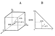
図3A、図3BはそれぞれRGB空間とr−g平面を示した例である。3次元の色空間の任意の一点(R1,G1,B1)は特定色を示しており、この点における色は次の数1のように投影法を用いて2次元の色度平面上における一点(r1,g1)で表示可能である。
【0024】
【数1】

したがって、3次元の色空間における全ての色は2次元の色度平面で記述可能であり、色相と彩度のような色の分類にも容易に適用が可能である。
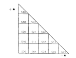
【0026】
図4は2次元の色度平面を15区間に分割するものであり、S00,S01,..,S40などに分割された小さいセルは色相と彩度の定義面において相異なる。したがって、各セル当たり入出力関係の定義は全体の色空間に対する入出力関係の定義より簡単な数式でさらに正確に表現することができる。この際、ディスプレイ機器の場合、例えば分割された小さい領域別の変換係数を求める過程は次のとおりである。
【0027】
第1段階では、RGB色信号別に32(または16)区間の間隔で0から255までのアドレスに9×9×9(=729)または17×17×17(=4913)の色を入力させ、CRTに該当色をCIExyYのような色座標値として測色して測定値として出力する。
【0028】
第2段階では、測定されたCIExyY値と入力されたRGB色信号とのRGBガンマ値(CIE X,CIE Y,CIE Z)を次の数2のように求める。
【0029】
【数2】
第3段階では、全ての測定されたCIExyz値は次の数3によりRrGrBr色値に換算される。
【0031】
【数3】
この際、変換行列Aは、NTSC規格を用いるカラーTV受像機の場合、RGB蛍光体の色度と白色点の定義とにより容易に得られる。
【0033】
第4段階では、2次元の領域で所定の大きさ、例えば32×32にセルを分割し、全ての換算されたRrGrBrを前記の数1に応じて2次元の色度平面に投影して各セルに属する測定値を得る。
【0034】
第5段階では、各セルにおける入力信号(RGB)と測定の信号(CIExyY=CIEXYZ)との入出力関係は次のように求める。まず、入力信号(RGB)に対して第2段階から得られた三つのガンマ値を適用して入力値と測定値との非線形性を取り除いた後、ガンマ補正されたた入力信号(RgGgBg)と曽測定値(CIEXYZ)との関係を次の数4により回帰分析して伝達関数Tを求める。
【0035】
【数4】
前記の数4において、mは任意のセルに属する測定値の合計を示す。
【0037】
第6段階では、入力信号(RGB)を前記の数3、数4を用いて次の数5のように色補正された出力信号(RcGcBc)に変換する。
【0038】
【数5】
第7段階では、第6段階から得られた領域別の変換行列Mの係数のうち、係数値の特性が類似した領域を集めて一つの領域とするセルグルーピングを全ての領域に対して繰り返して行うことにより、2次元の色度平面上における変換行列の数を最小とする。
【0040】
前記第1段階乃至第7段階を通して分割された領域別の係数値が得られると、係数値は第2ルックアップテーブル14に貯蔵され、第2ルックアップテーブル14に貯蔵された係数の位置を指定する値は第1ルックアップテーブル13に貯蔵する。第1及び第2ルックアップテーブル13,14に貯蔵されるデータの例が図5に示されている。
【0041】
この際、2次元の色度平面上における分割領域の大きさを小さくするほど、色信号の入出力関係がさらに正確になり、局部的な色調整もさらに精密になるが、9つの行列係数の集合で構成されるルックアップテーブルの大きさは非常に増える。したがって、分割領域の大きさは小さく維持しながら、分割された領域間の類似性質の色表現、すなわち類似した行列係数の値を有する領域を一つに集めると、行列係数の数を少なくすることができ、領域と該当行列係数との不規則なマッピング係数は第1ルックアップテーブル13の行列係数インデックステーブルに貯蔵する。
【0042】
本実施例では3次元の色空間を2次元の色度平面に投影し、2次元の色度平面上における各種の場合に色度領域の分割を試みたが、その結果は次のとおりである。
【0043】
まず、テストの対象としては29インチのカラーTV受像機のビデオ入力端からCRTまでの回路である。RGB空間におけるr,g平面領域を均等分割する例は次の表1のとおりである。表1からわかるように、55区間程度が色差面では適宜な領域分割である。55区間のうち、セルグルーピングを通して実際に用いられた行列係数は39個である。
【0044】
【表1】
図6は2次元の分割平面上における特定の好み色、すなわち、肌色、空色、灰色の分布を示す例であり、精密な色調整により好み色間の区別のためには分割の数を増やせることが望ましい。
【0046】
【発明の効果】
上述したように、本発明による2次元の色度分割を用いる色処理方法及び装置によれば、従来のルックアップテーブルと体積補間法を共に用いる方法と同じ色処理精密度を有しており、全体の色空間上における好み色に対してその他の色に影響を与えず、必要とする種類の色のみを局部的に調整することができ、かつ色処理が可能な構造を有する。
【0047】
かつ、本発明を具現するにおいては、必要とする追加装置が複雑でなく、基本的に画素処理時間は単純行列演算を用いることにより、計算に短時間がかかるので、実時間の画像処理装置でも使用可能である。
【0048】
さらに、カラーTV受像機などのディジタル信号処理を行う全てのディスプレイ機器及びカメラとプリンターなどの他の入出力装置にも広く用いることができる。
【図面の簡単な説明】
【図1】 本発明による2次元の色度分割を用いる色処理部が適用されるカラ−TV受像機を示すブロック図である。
【図2】 図1に示した本発明による色処理部の詳細ブロック図である。
【図3】 R,G,B色空間とr,g色平面の例を示す図面である。
【図4】 図3に示したr,g色平面における色度領域の分割概念図である。
【図5】 図2に示した第1ルックアップテーフルと第2ルックアップテーブルの構成図である。
【図6】 2次元の色度領域の分割と好み色の分布を示すグラフである。[0001]
BACKGROUND OF THE INVENTION
The present invention relates to a color processing method and apparatus using two-dimensional color division, and more particularly to minimizing a color error between a desired output color of a color display device and an actual output color using two-dimensional chromaticity division. The present invention relates to a color processing method and apparatus.
[0002]
[Prior art]
In general, a color display device, particularly a color TV receiver, receives a color signal according to a broadcast standard (NTSC or PAL), demodulates it, and reproduces it through a cathode ray tube (CRT). However, the received color signal causes color distortion due to various factors. One of the main factors is color signal processing in a color TV receiver. That is, a difference in color reproduction between the input color and the CRT output color generated when the R, G, B phosphor characteristics of the CRT are different from a predetermined law standard, and the intermediate color due to the non-linearity of the receiver circuit. Deviation also occurs. In addition, an output device such as a color TV receiver partially requires a visual color processing process that compensates for the shortage of primary colors or a difference in human color viewpoint.
[0003]
In order to solve this problem, as a representative device of the prior art, the received color signal is corrected to suit the user's preference by adjusting two reference phases in the chroma demodulation unit of the color TV receiver. Color correction devices (see U.S. Pat. No. 4,695,875) are widely used, but this device has the problem of causing general color distortion of other colors.
[0004]
Another conventional technique for characterizing a color device is a method of modeling a relationship between an input color and an output color value in the entire color space. Typical examples include a matrix method using a regression analysis method, and a method in which a lookup table and a volume interpolation method are combined. Of these, the latter is a method in which a large number of color values are measured in order to obtain the input / output relationship of the system, and intermediate values are expressed using the measurement points and the volume interpolation method. This method produces a more accurate result than the conventional method. In addition, since local color adjustment for visual color processing is possible, it is widely used in the printing field and the like. However, the volume interpolation method is complicated, and it is difficult to implement hardware for real-time processing in a display device such as a color TV receiver. There are disadvantages. Further, the matrix method using the regression analysis method is a method for easily matrixing the input / output relationship based on a large number of measurement points, and is widely used in the display device field. However, this method has a disadvantage in that the entire color space should be handled by one matrix, and local color adjustment such as visual color adjustment cannot be performed.
[0005]
As a recent method for solving the above problem, the color is divided into five sections of skin color, gray, R, G, and B, and a regression analysis method is applied to each section to try to characterize the color device. There is a way. However, by dividing the color into only five representative colors, there may be boundaries between the divided areas. In addition, there is a disadvantage in that it is difficult to appropriately express various hue characteristics represented by color mixing in a color device. In addition, there is a disadvantage that local color adjustment is difficult in a delicate hue portion of a mixed color of five representative colors.
[0006]
The problem described above is also a method of locally correcting a color by using a hue area divided into six in the chromaticity plane disclosed in US Pat. No. 4,989,080.
[0007]
[Problems to be solved by the invention]
Accordingly, an object of the present invention is to solve the above-mentioned problems by using a two-dimensional chromaticity division to distort the color signal in the color device, that is, the color between the phosphor characteristics of the CRT and the NTSC broadcast standard. It is an object of the present invention to provide a color processing method and apparatus capable of correcting a difference in reproducibility.
[0008]
Another object of the present invention is to provide a color processing method and apparatus capable of correcting a distortion factor of a color signal in a visual aspect, that is, a favorite color by using two-dimensional chromaticity division.
[0009]
[Means for Solving the Problems]
In order to achieve the above object, a color processing method using two-dimensional chromaticity division according to the present invention is divided into a plurality of small planes using three color signals for displaying an arbitrary point in a three-dimensional color space. A region designating step of designating one region on the two-dimensional chromaticity plane, obtaining a transform coefficient for each of the divided regions, and performing cell transformation on the transform coefficient through cell grouping for regions having similar transform coefficient characteristics. A transform coefficient obtaining step of reducing the number and storing it in a memory; an addressing step of designating an address of a memory storing a corresponding matrix transform coefficient value for each of the divided areas; and the designation from the memory A conversion coefficient reading step for reading out a matrix conversion coefficient corresponding to a given address, and a matrix operation is performed using the three color signals and the read matrix conversion coefficient to perform three conversions. A matrix operation step of obtaining a color signal, characterized in that it comprises a.
[0010]
The color processing apparatus using a two-dimensional chromaticity division according to the invention in order to achieve the object, on the three-dimensional R, G, B color signals or luminance signal (Y) and color difference signals (RY, BY) multiple An index calculation unit for calculating an index value to be projected onto a two-dimensional chromaticity plane divided into a plurality of areas and outputting the index value, and a predetermined address value corresponding to the index value are stored. And a matrix conversion coefficient that defines the input / output relationship of the R, G, B color signal or luminance signal ( Y ) and color difference signal (RY, BY) for each of the divided areas is stored. The number of stored transform coefficients is reduced through cell grouping for regions with similar transform coefficient characteristics, and the corresponding address specified by the output signal of the first look-up table. A second look-up table for outputting a predetermined number of conversion coefficients stored in the R, G, B color signals or Y, using a predetermined number of conversion coefficients output from the second look-up table as inputs. characterized in that it comprises a color conversion calculation unit for outputting the R-Y, converted color signal by performing matrix operation with respect to B-Y signal.
[0011]
In order to achieve the above object, a color processing apparatus using two-dimensional chromaticity division according to the present invention provides a plurality of three-dimensional R, G, B color signals or luminance signals ( Y ) and color difference signals (RY, BY) . An index calculation unit for calculating an index value to be projected onto a two-dimensional chromaticity plane divided into a plurality of regions and outputting the index value, and the R, G, and B colors for each of the divided regions Stores conversion coefficients of a matrix that defines the input / output relationship of a signal or luminance signal ( Y ) and color difference signals (RY, BY) , and stores the number of conversion coefficients stored through cell grouping for regions with similar characteristics of the conversion coefficients There is reduced, and a look-up table for outputting a transform coefficient of a predetermined number which is stored in the designated address corresponding to the output signal of the first look-up table, out of the said look-up table A color conversion calculation unit that outputs a color signal converted by performing matrix calculation on the R, G, B color signals or Y, RY, BY signals, with a predetermined number of conversion coefficients being input characterized in that it comprises a and.
[0012]
DETAILED DESCRIPTION OF THE INVENTION
Hereinafter, embodiments of the present invention will be described in detail with reference to the accompanying drawings.
[0013]
FIG. 1 is a block diagram showing a color TV receiver to which a color processing apparatus using two-dimensional chromaticity division according to the present invention is applied. A tuner that tunes a received modulated color signal and converts it to an intermediate frequency IF. &
[0014]
FIG. 2 is a detailed block diagram of the
[0015]
On the other hand, the operation and effect of the present invention will be described based on the configurations of FIGS. 1 and 2 as follows.
[0016]
In FIG. 1 and FIG. 2, R, G, B color signals or luminance signals (Y) and color difference signals (R−Y, B−Y) output from the demodulation &
[0017]
The gamma
[0018]
The
[0019]
The first look-up table (LUT-1) 13 is a table in which index values are stored. For example, when 5 bits each of r and g are allocated, the size is 16 × 16 (= 136 cells). Have. Numbers from 0 to 136 are stored in each cell. The second look-up table (LUT-2) 14 is a table in which the coefficients of the transformation matrix defining the input / output relationship of the R, G, B color signals are stored. Nine coefficients are set as one set, and a maximum of 136 sets can be used. However, there is no restriction on the actual number of sets. The output signal of the first look-up table 13 designates the corresponding address of the second look-up table 14, and the second look-up table 14 performs color conversion on nine (3 × 3) conversion coefficients stored in the corresponding address. The result is output to the
[0020]
The color
[0021]
In the case of a color TV receiver, the RGB
[0022]
As described above, the color signal subjected to color conversion and gamma correction output from the
[0023]
3A and 3B are examples showing an RGB space and an rg plane, respectively. An arbitrary point (R1, G1, B1) in the three-dimensional color space indicates a specific color, and the color at this point is a point on the two-dimensional chromaticity plane using the projection method as shown in the following equation (1). (R1, g1) can be displayed.
[0024]
[Expression 1]
Therefore, all the colors in the three-dimensional color space can be described in a two-dimensional chromaticity plane, and can be easily applied to color classification such as hue and saturation.
[0026]
4 divides the two-dimensional chromaticity plane into 15 sections, and S00, S01,. . , S40 and the like are different in terms of the definition of hue and saturation. Therefore, the definition of the input / output relationship for each cell can be expressed more accurately by a simpler mathematical expression than the definition of the input / output relationship for the entire color space. At this time, in the case of a display device, for example, a process for obtaining a conversion coefficient for each divided small area is as follows.
[0027]
In the first stage, 9 × 9 × 9 (= 729) or 17 × 17 × 17 (= 4913) color is input to addresses from 0 to 255 at intervals of 32 (or 16) intervals for each RGB color signal, The color corresponding to the CRT is measured as a color coordinate value such as CIExyY and output as a measurement value.
[0028]
In the second stage, an RGB gamma value (CIE) between the measured CIExyY value and the input RGB color signal. X, CIE Y, CIE Z) is obtained as in the following equation (2).
[0029]
[Expression 2]
In the third stage, all measured CIEExyz values are converted to RrGrBr color values by the following equation (3).
[0031]
[Equation 3]
At this time, the conversion matrix A can be easily obtained by defining the chromaticity of the RGB phosphor and the white point in the case of a color TV receiver using the NTSC standard.
[0033]
In the fourth stage, a cell is divided into a predetermined size, for example, 32 × 32 in a two-dimensional area, and all the converted RrGrBr are projected onto a two-dimensional chromaticity plane according to the
[0034]
In the fifth stage, the input / output relationship between the input signal (RGB) and the measurement signal (CIExyY = CIEXYZ) in each cell is obtained as follows. First, after applying the three gamma values obtained from the second stage to the input signal (RGB) to remove the non-linearity between the input value and the measured value, the input signal (RgGgBg) subjected to gamma correction and The transfer function T is obtained by performing regression analysis on the relationship with the measured value (CIEXYZ) by the following equation (4).
[0035]
[Expression 4]
In the above equation 4, m represents the total of measured values belonging to an arbitrary cell.
[0037]
In the sixth stage, the input signal (RGB) is converted into an output signal (RcGcBc) that has been color-corrected as shown in the following equation 5 using the
[0038]
[Equation 5]
In the seventh stage, cell grouping is repeated for all areas by collecting areas having similar coefficient value characteristics among the coefficients of the transformation matrix M for each area obtained from the sixth stage. By doing so, the number of transformation matrices on the two-dimensional chromaticity plane is minimized.
[0040]
When the region-specific coefficient values obtained through the first to seventh steps are obtained, the coefficient values are stored in the second lookup table 14 and the positions of the coefficients stored in the second lookup table 14 are designated. The value to be stored is stored in the first lookup table 13. An example of data stored in the first and second lookup tables 13 and 14 is shown in FIG.
[0041]
At this time, the smaller the size of the divided area on the two-dimensional chromaticity plane, the more accurate the input / output relationship of the color signal and the more precise the local color adjustment. The size of the lookup table composed of sets is greatly increased. Therefore, while keeping the size of the divided area small, if the color representation of similar properties between the divided areas, that is, collecting areas having similar matrix coefficient values into one, the number of matrix coefficients is reduced. The irregular mapping coefficient between the region and the corresponding matrix coefficient is stored in the matrix coefficient index table of the first lookup table 13.
[0042]
In this embodiment, a three-dimensional color space is projected onto a two-dimensional chromaticity plane, and division of the chromaticity region is attempted in various cases on the two-dimensional chromaticity plane. The result is as follows. .
[0043]
First, a test object is a circuit from a video input end to a CRT of a 29-inch color TV receiver. An example of equally dividing the r and g plane regions in the RGB space is as shown in Table 1 below. As can be seen from Table 1, about 55 sections are appropriate area divisions in the color difference plane. Of the 55 sections, 39 matrix coefficients are actually used through cell grouping.
[0044]
[Table 1]
FIG. 6 shows an example of the distribution of specific favorite colors on the two-dimensional division plane, that is, skin color, sky blue, and gray. By precise color adjustment, the number of divisions can be increased to distinguish between favorite colors. Is desirable.
[0046]
【The invention's effect】
As described above, according to the color processing method and apparatus using two-dimensional chromaticity division according to the present invention, it has the same color processing precision as the method using both the conventional lookup table and the volume interpolation method, The preferred color on the entire color space does not affect other colors, and only a necessary type of color can be locally adjusted, and color processing is possible.
[0047]
In addition, in implementing the present invention, the required additional device is not complicated, and the pixel processing time basically takes a short time to calculate by using a simple matrix operation. Even in a real-time image processing device, It can be used.
[0048]
Furthermore, it can be widely used for all display devices that perform digital signal processing such as a color TV receiver and other input / output devices such as cameras and printers.
[Brief description of the drawings]
FIG. 1 is a block diagram illustrating a color TV receiver to which a color processing unit using two-dimensional chromaticity division according to the present invention is applied.
FIG. 2 is a detailed block diagram of a color processing unit according to the present invention shown in FIG.
FIG. 3 is a diagram illustrating an example of an R, G, B color space and an r, g color plane.
4 is a conceptual diagram of division of chromaticity regions in the r and g color planes shown in FIG. 3. FIG.
FIG. 5 is a configuration diagram of a first lookup table and a second lookup table shown in FIG. 2;
FIG. 6 is a graph showing the division of a two-dimensional chromaticity region and the distribution of favorite colors.
Claims (6)
前記分割された各領域に対して変換係数を求め、変換係数の特性が類似した領域に対するセルグルーピングを通して前記変換係数の数を縮小させメモリに貯蔵する変換係数獲得段階と、
前記分割された各領域に対して該当行列変換係数値を貯蔵しているメモリのアドレスを指定するアドレス指定段階と、
前記メモリから前記指定されたアドレスに該当する行列変換係数を読出す変換係数読出し段階と、
前記三つの色信号と前記読出した行列変換係数とにより行列演算を行って三つの変換された色信号を得る行列演算段階と、
を備えることを特徴とする2次元の色度分割を用いる色処理方法。A region designating step of designating one region on a two-dimensional chromaticity plane divided into a plurality of small planes using three color signals displaying an arbitrary point on a three-dimensional color space;
Obtaining a transform coefficient for each of the divided regions, obtaining a transform coefficient by reducing the number of transform coefficients and storing the transform coefficient in a memory through cell grouping for regions with similar transform coefficient characteristics;
An addressing step of designating an address of a memory storing a corresponding matrix transformation coefficient value for each of the divided areas;
A conversion coefficient reading step of reading out a matrix conversion coefficient corresponding to the designated address from the memory;
A matrix operation step of performing a matrix operation using the three color signals and the read matrix conversion coefficient to obtain three converted color signals ;
A color processing method using two-dimensional chromaticity division.
R,G,B色信号別に所定の区間間隔で0から255まで所定の数の色を入力させ、該当色を所定の色座標値として測色して測定値として出力する段階と、
前記測定された色座標値を所定の変換行列を用いてRr,Gr,Br色値に換算する段階と、
2次元の色度表面において所定の大きさに領域を分割し、前記換算されたRr,Gr,Brを前記2次元の色度平面に投影して各領域に属する測定値を求め、前記分割された各領域で前記R,G,B色信号と測定された色座標値との入出力関係を求める段階と、
前記入出力関係から前記R,G,B色信号を色補正されたRc,Gc,Bc信号に変換する領域別の変換行列を求める段階と、
前記領域別の変換行列の係数のうち、係数値の特性が類似した領域を集めて一つの領域とするセルグルーピングを全ての領域に対して繰り返して行って2次元の色度平面上において変換行列の数を最小とする段階とを備えることを特徴とする請求項1に記載の2次元の色度分割を用いる色処理方法。The conversion coefficient acquisition step includes:
Inputting a predetermined number of colors from 0 to 255 at predetermined intervals for each of the R, G, B color signals, measuring the corresponding color as a predetermined color coordinate value, and outputting it as a measurement value;
Converting the measured color coordinate values into Rr, Gr, and Br color values using a predetermined conversion matrix;
A region is divided into a predetermined size on the two-dimensional chromaticity surface, and the converted Rr, Gr, and Br are projected onto the two-dimensional chromaticity plane to obtain a measurement value belonging to each region, and the divided Obtaining an input / output relationship between the R, G, B color signals and the measured color coordinate values in each region;
Obtaining a region-specific transformation matrix for transforming the R, G, B color signals into color-corrected Rc, Gc, Bc signals from the input / output relationship;
Among the coefficients of the transform matrix for each region, cell grouping that collects regions having similar characteristics of the coefficient values to form one region is repeated for all regions, and the transform matrix is displayed on a two-dimensional chromaticity plane. The color processing method using two-dimensional chromaticity division according to claim 1, further comprising:
前記インデックス値に対応する所定のアドレス値が貯蔵されている第1ルックアップテーブルと、
前記分割された各領域に対する前記R、G、B色信号または輝度信号 ( Y ) 及び色差信号 (R-Y, B-Y)の入出力関係を定義する行列の変換係数が貯蔵されており、変換係数の特性が類似した領域に対するセルグルーピングを通して前記貯蔵される変換係数の数が縮小され、前記第1ルックアップテーブルの出力信号により指定された該当アドレスに貯蔵されている所定個数の変換係数を出力する第2ルックアップテーブルと、
前記第2ルックアップテーブルから出力される所定の数の変換係数を入力として前記R,G,B色信号またはY,R−Y,B−Y信号に対して行列演算を行って変換された色信号を出力する色変換演算部と、
を備えることを特徴とする2次元の色度分割を用いる色処理装置。 Calculates an index value for projecting a three-dimensional R, G, B color signal or luminance signal (Y) and color difference signal (RY, BY) onto a two-dimensional chromaticity plane divided into a plurality of regions. An index calculation unit for outputting the index value ;
A first lookup table in which a predetermined address value corresponding to the index value is stored ;
Conversion coefficients of a matrix defining input / output relationships of the R, G, B color signals or luminance signals ( Y ) and color difference signals (RY, BY) for each of the divided areas are stored , and characteristics of the conversion coefficients are stored. The number of stored transform coefficients is reduced through cell grouping for similar regions, and a predetermined number of transform coefficients stored in the corresponding address specified by the output signal of the first lookup table is output . A lookup table,
Color converted by performing matrix operation on the R, G, B color signals or Y, RY, BY signals with a predetermined number of conversion coefficients output from the second look-up table as input A color conversion operation unit for outputting a signal ;
A color processing apparatus using two-dimensional chromaticity division.
前記色変換演算部から出力される変換された色信号を表示する関連回路のRGBガンマ特性を線形的に補償するRGBガンマ補正部をさらに含むことを特徴とする請求項3に記載の2次元の色度分割を用いる色処理装置。Gamma reverse correction that reversely corrects the gamma component so as to linearize the gamma component of the R, G, B color signal or Y, RY, BY signal and applies it to the index calculation unit and the color conversion calculation unit. And
The two-dimensional gamma correction unit according to claim 3 , further comprising an RGB gamma correction unit that linearly compensates an RGB gamma characteristic of an associated circuit that displays the converted color signal output from the color conversion calculation unit. A color processing apparatus using chromaticity division.
前記分割された各領域に対する前記R、G、B色信号または輝度信号 ( Y ) 及び色差信号 (R-Y, B-Y)の入出力関係を定義する行列の変換係数を貯蔵し、変換係数の特性が類似した領域に対するセルグルーピングを通して前記貯蔵される変換係数の数が縮小され、前記第1ルックアップテーブルの出力信号により指定された該当アドレスに貯蔵されている所定個数の変換係数を出力するルックアップテーブルと、
前記ルックアップテーブルから出力される所定の数の変換係数を入力として前記R,G,B色信号またはY,R−Y,B−Y信号に対して行列演算を行って変換された色信号を出力する色変換演算部と、
を備えることを特徴とする2次元の色度分割を用いる色処理装置。 Calculates an index value for projecting a three-dimensional R, G, B color signal or luminance signal ( Y ) and color difference signal (RY, BY) onto a two-dimensional chromaticity plane divided into a plurality of regions. An index calculation unit for outputting the index value ;
Stores conversion coefficients of a matrix that defines the input / output relationship of the R, G, B color signals or luminance signals ( Y ) and color difference signals (RY, BY) for each of the divided areas , and the characteristics of the conversion coefficients are similar. A lookup table for outputting a predetermined number of transformation coefficients stored at a corresponding address specified by an output signal of the first lookup table, wherein the number of the transformation coefficients stored is reduced through cell grouping for the selected region ; ,
A color signal converted by performing a matrix operation on the R, G, B color signal or Y, RY, BY signal with a predetermined number of conversion coefficients output from the lookup table as input. An output color conversion operation unit ;
A color processing apparatus using two-dimensional chromaticity division.
前記色信号演算部から出力される変換された色信号を表示する関連回路のR,G,Bガンマ特性を線形的に補償するRGBガンマ補正部をさらに備えることを特徴とする請求項5に記載の2次元の色度分割を用いる色処理装置。The apparatus reversely corrects gamma so as to linearize the gamma component of the input R, G, B color signal or Y, RY, BY signal, and applies the inverse gamma to the index calculation unit. A correction unit;
According to claim 5, further comprising an RGB gamma correction unit that compensates R associated circuitry for displaying the converted color signals outputted from the color signal calculating unit, G, and B gamma characteristic linearly A color processing apparatus using the two-dimensional chromaticity division.
Applications Claiming Priority (2)
| Application Number | Priority Date | Filing Date | Title |
|---|---|---|---|
| KR95P69696 | 1995-12-30 | ||
| KR1019950069696A KR100363250B1 (en) | 1995-12-30 | 1995-12-30 | Method and system for processing colors using two-dimensional chrominance division |
Publications (2)
| Publication Number | Publication Date |
|---|---|
| JPH09200790A JPH09200790A (en) | 1997-07-31 |
| JP3768630B2 true JP3768630B2 (en) | 2006-04-19 |
Family
ID=19448534
Family Applications (1)
| Application Number | Title | Priority Date | Filing Date |
|---|---|---|---|
| JP34589696A Expired - Fee Related JP3768630B2 (en) | 1995-12-30 | 1996-12-25 | Color processing method and apparatus using two-dimensional chromaticity division |
Country Status (6)
| Country | Link |
|---|---|
| US (1) | US5867286A (en) |
| JP (1) | JP3768630B2 (en) |
| KR (1) | KR100363250B1 (en) |
| CN (1) | CN1091994C (en) |
| DE (1) | DE19654715B4 (en) |
| NL (1) | NL1004906C2 (en) |
Families Citing this family (29)
| Publication number | Priority date | Publication date | Assignee | Title |
|---|---|---|---|---|
| KR100189908B1 (en) * | 1996-05-06 | 1999-06-01 | 윤종용 | Color correction apparatus & method therefor using two-dimensional chromaticity partitioning |
| JPH10178557A (en) * | 1996-10-14 | 1998-06-30 | Oki Data:Kk | Color image processing method |
| JP2001054131A (en) * | 1999-05-31 | 2001-02-23 | Olympus Optical Co Ltd | Color image display system |
| US20020027603A1 (en) * | 2000-09-01 | 2002-03-07 | Seiko Epson Corporation | Apparatus, method, signal and computer program product configured to provide output image adjustment for image files |
| US6950109B2 (en) * | 2000-10-23 | 2005-09-27 | Sun Microsystems, Inc. | Multi-spectral color correction |
| KR20010016210A (en) * | 2000-11-22 | 2001-03-05 | 유진철 | Method for processing simple color images |
| KR20010016607A (en) * | 2000-12-26 | 2001-03-05 | 히로시 나카야마 | 2 omitted |
| JP3729252B2 (en) | 2001-03-26 | 2005-12-21 | セイコーエプソン株式会社 | Image processing system, program, and information storage medium |
| AU2002309213A1 (en) | 2001-06-07 | 2002-12-16 | Genoa Technologies Ltd. | System and method of data conversion for wide gamut displays |
| US7006699B2 (en) * | 2002-03-27 | 2006-02-28 | Microsoft Corporation | System and method for progressively transforming and coding digital data |
| JP2003319412A (en) * | 2002-04-19 | 2003-11-07 | Matsushita Electric Ind Co Ltd | Image processing back-up system, image processor, and image display device |
| US6833839B2 (en) * | 2002-05-13 | 2004-12-21 | Genesis Microchip Inc. | Apparatus and method for multi-resolution color mapping for display devices |
| US7019776B1 (en) * | 2002-08-16 | 2006-03-28 | Magnachip Semiconductor, Inc. | Method and system for automatic white balancing |
| US6956581B2 (en) * | 2002-09-19 | 2005-10-18 | Lexmark International, Inc. | Gamut mapping algorithm for business graphics |
| US7079705B2 (en) * | 2002-10-30 | 2006-07-18 | Agilent Technologies, Inc. | Color interpolation for image sensors using a local linear regression method |
| JP4272880B2 (en) * | 2002-12-18 | 2009-06-03 | キヤノン株式会社 | Color correction method, image processing apparatus, and lookup table |
| EP1701554B1 (en) | 2003-12-24 | 2013-06-19 | National University Corporation Shizuoka University | Color display system with accurate conversion between the RGB and XYZ colorimetric systems |
| US20050259109A1 (en) * | 2004-05-19 | 2005-11-24 | Microsoft Corporation | System and method for a gamut mapping platform having plug-in transform functions |
| CN100407288C (en) * | 2005-03-22 | 2008-07-30 | 广达电脑股份有限公司 | Method and apparatus for adjusting input image in accordance with display system characteristics |
| CN100450144C (en) * | 2005-06-17 | 2009-01-07 | 诚研科技股份有限公司 | Color managing method for pixel capable of transforming different color domain |
| KR100771618B1 (en) * | 2005-09-29 | 2007-10-30 | 엘지전자 주식회사 | Apparatus and Method for Mediation Color |
| KR100790983B1 (en) * | 2006-02-22 | 2008-01-02 | 삼성전자주식회사 | Visualization method and tuning method of 3*3 matrix's coefficients for color correction and computer-readable medium for recording the method |
| JP4676364B2 (en) | 2006-03-17 | 2011-04-27 | 富士通株式会社 | Color correction method, color correction apparatus, and color correction program |
| JP2007293431A (en) * | 2006-04-21 | 2007-11-08 | Megachips Lsi Solutions Inc | Image processor |
| KR100970883B1 (en) * | 2008-10-08 | 2010-07-20 | 한국과학기술원 | The apparatus for enhancing image considering the region characteristic and method therefor |
| US8311360B2 (en) | 2008-11-13 | 2012-11-13 | Seiko Epson Corporation | Shadow remover |
| CN104601971B (en) | 2014-12-31 | 2019-06-14 | 小米科技有限责任公司 | Color adjustment method and device |
| CN104767521B (en) * | 2015-04-30 | 2018-01-12 | 福州大学 | A kind of circuit and its control method that can carry out plus-minus counting simultaneously |
| CN111064944B (en) * | 2019-12-05 | 2021-11-02 | 华侨大学 | Colorless constant white balance method |
Family Cites Families (10)
| Publication number | Priority date | Publication date | Assignee | Title |
|---|---|---|---|---|
| US4695875A (en) * | 1985-03-14 | 1987-09-22 | Sanyo Electric Co., Ltd. | Automatic hue correction circuit |
| JP2678007B2 (en) * | 1988-03-08 | 1997-11-17 | 株式会社リコー | Color information correction device |
| US5398123A (en) * | 1988-08-31 | 1995-03-14 | Canon Kabushiki Kaisha | Image processing method and apparatus capable of automatic color masking |
| JP2846428B2 (en) * | 1990-07-18 | 1999-01-13 | 株式会社アドバンテスト | Logical comparison circuit |
| JP2699711B2 (en) * | 1991-09-17 | 1998-01-19 | 松下電器産業株式会社 | Tone correction method and apparatus |
| JPH05103335A (en) * | 1991-10-03 | 1993-04-23 | Jiemuko:Kk | Method and device for correcting color |
| JP3400506B2 (en) * | 1993-03-12 | 2003-04-28 | オリンパス光学工業株式会社 | Image processing device |
| KR950004881A (en) * | 1993-07-31 | 1995-02-18 | 김광호 | Color image processing method and device |
| KR100300950B1 (en) * | 1994-01-31 | 2001-10-22 | 윤종용 | Method and apparatus for correcting color |
| US5650942A (en) * | 1996-02-02 | 1997-07-22 | Light Source Computer Images, Inc. | Appearance-based technique for rendering colors on an output device |
-
1995
- 1995-12-30 KR KR1019950069696A patent/KR100363250B1/en not_active IP Right Cessation
-
1996
- 1996-12-25 JP JP34589696A patent/JP3768630B2/en not_active Expired - Fee Related
- 1996-12-30 DE DE19654715A patent/DE19654715B4/en not_active Expired - Fee Related
- 1996-12-30 US US08/774,653 patent/US5867286A/en not_active Expired - Fee Related
- 1996-12-30 NL NL1004906A patent/NL1004906C2/en not_active IP Right Cessation
- 1996-12-30 CN CN96123949A patent/CN1091994C/en not_active Expired - Fee Related
Also Published As
| Publication number | Publication date |
|---|---|
| NL1004906A1 (en) | 1997-07-02 |
| DE19654715B4 (en) | 2006-08-31 |
| CN1160326A (en) | 1997-09-24 |
| KR100363250B1 (en) | 2003-03-15 |
| KR970058032A (en) | 1997-07-31 |
| DE19654715A1 (en) | 1997-07-03 |
| US5867286A (en) | 1999-02-02 |
| NL1004906C2 (en) | 1999-09-28 |
| JPH09200790A (en) | 1997-07-31 |
| CN1091994C (en) | 2002-10-02 |
Similar Documents
| Publication | Publication Date | Title |
|---|---|---|
| JP3768630B2 (en) | Color processing method and apparatus using two-dimensional chromaticity division | |
| US5553199A (en) | Method and apparatus for calibrating a four color printer | |
| US6343147B2 (en) | Print preview and setting background color in accordance with a gamma value, color temperature and illumination types | |
| US5481655A (en) | System for matching a picture on a monitor to a printed picture | |
| JP3290870B2 (en) | Color conversion adjustment method and apparatus | |
| US8265411B2 (en) | Image recording apparatus, image recording method, image processing apparatus, image processing method and image processing system | |
| US20090060326A1 (en) | Image processing apparatus and method | |
| JP2000278546A (en) | Device and method for image processing, device and method for color gamut conversion table preparation, recording medium recording image processing program and recording medium recording color gamut conversion table preparation program | |
| US20080095430A1 (en) | Maintenance of Color Maximum Values in a Color Saturation Controlled Color Image | |
| JPH05183742A (en) | Device for deciding color compensation parameter | |
| JP3519230B2 (en) | Color correction method for image data | |
| JP3354158B2 (en) | Color correction device, color correction method, and color correction application device | |
| EP1011263B1 (en) | A method of color correction using multi-level halftoning | |
| JP2002041000A (en) | Liquid crystal display device and its color correcting method | |
| KR100408508B1 (en) | Method and apparatus for processing color, signal using color difference plane separation | |
| JPH04335771A (en) | Color correcting device | |
| JP2002027263A (en) | Image processing method | |
| JP2845523B2 (en) | Color estimation method | |
| JP2000134487A (en) | Color conversion device | |
| JPH1074074A (en) | Color correcting device and method using two-dimensional chromaticity division | |
| CN1862653A (en) | Method and system for display color correction | |
| JPH05292303A (en) | Color picture printer | |
| JP5041538B2 (en) | System and method for adjusting color image quality | |
| JP2000341550A (en) | Color image signal processor | |
| Kutschbach | A color volume mapping system for perception-accurate reproduction of HDR imagery in SDR production workflows |
Legal Events
| Date | Code | Title | Description |
|---|---|---|---|
| A977 | Report on retrieval |
Free format text: JAPANESE INTERMEDIATE CODE: A971007 Effective date: 20050610 |
|
| A131 | Notification of reasons for refusal |
Free format text: JAPANESE INTERMEDIATE CODE: A131 Effective date: 20050614 |
|
| A601 | Written request for extension of time |
Free format text: JAPANESE INTERMEDIATE CODE: A601 Effective date: 20050914 |
|
| A602 | Written permission of extension of time |
Free format text: JAPANESE INTERMEDIATE CODE: A602 Effective date: 20050920 |
|
| A521 | Request for written amendment filed |
Free format text: JAPANESE INTERMEDIATE CODE: A523 Effective date: 20051214 |
|
| TRDD | Decision of grant or rejection written | ||
| A01 | Written decision to grant a patent or to grant a registration (utility model) |
Free format text: JAPANESE INTERMEDIATE CODE: A01 Effective date: 20060117 |
|
| A61 | First payment of annual fees (during grant procedure) |
Free format text: JAPANESE INTERMEDIATE CODE: A61 Effective date: 20060202 |
|
| R150 | Certificate of patent or registration of utility model |
Free format text: JAPANESE INTERMEDIATE CODE: R150 |
|
| FPAY | Renewal fee payment (event date is renewal date of database) |
Free format text: PAYMENT UNTIL: 20100210 Year of fee payment: 4 |
|
| LAPS | Cancellation because of no payment of annual fees |