JP3768455B2 - Orthogonal excitation laser oscillator - Google Patents
Orthogonal excitation laser oscillator Download PDFInfo
- Publication number
- JP3768455B2 JP3768455B2 JP2002109694A JP2002109694A JP3768455B2 JP 3768455 B2 JP3768455 B2 JP 3768455B2 JP 2002109694 A JP2002109694 A JP 2002109694A JP 2002109694 A JP2002109694 A JP 2002109694A JP 3768455 B2 JP3768455 B2 JP 3768455B2
- Authority
- JP
- Japan
- Prior art keywords
- optical
- axis
- oscillator
- leaf spring
- end portion
- Prior art date
- Legal status (The legal status is an assumption and is not a legal conclusion. Google has not performed a legal analysis and makes no representation as to the accuracy of the status listed.)
- Expired - Lifetime
Links
Images


Classifications
-
- H—ELECTRICITY
- H01—ELECTRIC ELEMENTS
- H01S—DEVICES USING THE PROCESS OF LIGHT AMPLIFICATION BY STIMULATED EMISSION OF RADIATION [LASER] TO AMPLIFY OR GENERATE LIGHT; DEVICES USING STIMULATED EMISSION OF ELECTROMAGNETIC RADIATION IN WAVE RANGES OTHER THAN OPTICAL
- H01S3/00—Lasers, i.e. devices using stimulated emission of electromagnetic radiation in the infrared, visible or ultraviolet wave range
- H01S3/02—Constructional details
- H01S3/03—Constructional details of gas laser discharge tubes
- H01S3/036—Means for obtaining or maintaining the desired gas pressure within the tube, e.g. by gettering, replenishing; Means for circulating the gas, e.g. for equalising the pressure within the tube
-
- H—ELECTRICITY
- H01—ELECTRIC ELEMENTS
- H01S—DEVICES USING THE PROCESS OF LIGHT AMPLIFICATION BY STIMULATED EMISSION OF RADIATION [LASER] TO AMPLIFY OR GENERATE LIGHT; DEVICES USING STIMULATED EMISSION OF ELECTROMAGNETIC RADIATION IN WAVE RANGES OTHER THAN OPTICAL
- H01S3/00—Lasers, i.e. devices using stimulated emission of electromagnetic radiation in the infrared, visible or ultraviolet wave range
- H01S3/14—Lasers, i.e. devices using stimulated emission of electromagnetic radiation in the infrared, visible or ultraviolet wave range characterised by the material used as the active medium
- H01S3/22—Gases
- H01S3/223—Gases the active gas being polyatomic, i.e. containing two or more atoms
- H01S3/2232—Carbon dioxide (CO2) or monoxide [CO]
Description
【0001】
【発明の属する技術分野】
この発明は、発振器筐体が熱によって変形した場合にも、一対の光共振器の平行度や軸ずれなどの位置関係を一定に保つことによって、レーザビームの出力やビームモードなどの品質を安定に保つことが可能な構造を有する直交励起型レーザ発振器に関するものである。
【0002】
【従来の技術】
ガスレーザ発振器は、一般に、レーザ気体が封入されて放電によりレーザを励起する放電管と、この放電管の両側に配置される2枚のミラーを有する光共振器とを備えている。レーザ発振時に放電管で大きい発熱が生じると、その熱の一部が光共振器、または放電管や光共振器を支持しているベース板側に伝達し、それらが熱により変形する結果、光共振器を構成する一対の光学基台の平行度の狂いや、光共振器の軸と発振器筐体の軸との間の位置のずれなどを生じる。また、光共振器自体も外気温度の変化によりフレームの棒部材、端面板部材等の構成部材相互の間で熱膨張差を生じ、これによっても光共振器の位置のずれなどを生じる恐れがある。このような光共振器の位置のずれは、ミラーアライメントの狂いを招来して、レーザ光のレーザ出力やビームモードを不安定にする。そこで、このような熱の影響による光共振器の位置のずれなどに対処するために、種々の構成を有するレーザ発振器が提案されている。
【0003】
従来のレーザ発振器に関する発明としては、図12に示す特開2000−183425号公報に開示されている従来技術がある。この従来技術では、発振器筐体1の両側に、前部光学基台9と後部光学基台7とが設けられている。前部光学基台9には部分反射鏡が、後部光学基台7には全反射鏡が固定されており、部分反射鏡と全反射鏡とが同一光軸上に互いに平行に固定されるように、前部光学基台9と後部光学基台7とは、下部1本、上部2本の合計3本のレーザビーム進行方向(光軸方向)に延在する支持棒112〜114によって互いに剛固に接続されている。発振器筐体1上側における支持棒113,114は、それぞれ軸方向中央部をブラケット120,121によって発振器筐体1上面の光軸方向中央部分に接続されている。熱変形の少ない送風器側に位置する支持棒113の発振器筐体1に対するブラケット120による接続は完全な固定接続であり、他方の高温側に位置する支持棒114の発振器筐体1に対するブラケット121による接続は、軸方向および高さ方向の動きを拘束したスライド台122による可動接続とされている。すなわち、ブラケット121は、矢印で示すように左右方向にスライド台122上をスライド可能である。下部の支持棒112は、発振器筐体1とブラケットによる接続はなされておらず、支持棒112の両端が光学基台9,7に固定されているのみである。発振器筐体1と後部光学基台7との間および発振器筐体1と前部光学基台9との間のレーザビーム通過部分は、それぞれベローズによって接続されている。
【0004】
【発明が解決しようとする課題】
上述した従来技術のものにあっては、3本の支持棒112〜114とブラケット120,121による支持構造によって、レーザ媒質ガスの温度分布による2つの光学基台7,9間の位置関係の変化を抑えることが可能であるけれども、発振器筐体1はレーザ媒質ガスの温度分布によって自由に熱変形するため、その両端面の位置や角度は変化してしまう。その結果、発振器筐体1両端に取り付けられたベローズの位置が変化する。一般に、ベローズの芯ずれ方向の剛性は軸方向の剛性に比べて非常に大きく、ベローズの位置がずれることによって有害な反力が発生する。この反力によって、光共振器の構造体が変形し、2つの光学基台9,7の位置関係が崩れてしまう。そして、このような光学基台9,7の位置関係のずれは、レーザ出力またはビームモードを不安定にする。
【0005】
この発明は、上記に鑑みてなされたもので、発振器筐体が熱変形しても、平行に配置された二つの光学基台と支持棒とからなる光共振器が変形力を受けないようにすることができる直交励起型レーザ発振器を得ることを目的とする。
【0006】
【課題を解決するための手段】
上記目的を達成するため、この発明にかかる直交励起型レーザ発振器は、発振器筐体と、前記発振器筐体の両側に設置され、光軸方向に延在する少なくとも3本の支持棒によって互いに平行接続された、光共振器を構成する光学部品をそれぞれ支持する一対の光学基台と、前記一対の光学基台と前記発振器筐体との間を接続する一対のベローズとを備える直交励起型レーザ発振器において、前記光共振器の光軸方向をY軸とし、前記光軸方向に垂直な高さ方向をZ軸とし、前記Y軸およびZ軸に垂直な方向をX軸とした場合、前記光学基台側と接続されている前記ベローズの中心位置が、前記発振器筐体の側端部側と接続されている前記ベローズの中心位置に対して、X軸およびZ軸方向の曲げ運動とY軸まわりの回転運動を拘束し、Y軸方向の曲げ運動とX軸およびZ軸まわりの回転運動を可能とするように、前記発振器筐体の側端部と前記光学基台とを連結する連結部材を備えることを特徴とする。
【0007】
この発明によれば、光学基台側と接続されているベローズの中心位置が、発振器筐体の側端部側と接続されているベローズの中心位置に対して、X軸およびZ軸方向の曲げ運動とY軸まわりの回転運動を拘束し、Y軸方向の曲げ運動とX軸およびZ軸まわりの回転運動を可能とするように、発振器筐体の側端部と光学基台とを連結する連結部材を備えるようにしている。
【0008】
つぎの発明にかかる直交励起型レーザ発振器は、上記の発明において、前記連結部材は、板バネによって構成されることを特徴とする。
【0009】
この発明によれば、連結部材は、板バネによって構成されるようにしている。
【0010】
つぎの発明にかかる直交励起型レーザ発振器は、上記の発明において、前記連結部材はコの字型形状の板バネによって構成されることを特徴とする。
【0011】
この発明によれば、連結部材はコの字型形状の板バネによって構成されるようにしている。
【0012】
つぎの発明にかかる直交励起型レーザ発振器は、上記の発明において、前記板バネの上端部は前記発振器筐体の側端部側で支持され、その下端部は前記光学基台側で支持されることを特徴とする。
【0013】
この発明によれば、板バネの上端部は発振器筐体の側端部側で支持され、その下端部は光学基台側で支持されるようにしている。
【0014】
つぎの発明にかかる直交励起型レーザ発振器は、上記の発明において、前記板バネの下端部は前記発振器筐体の側端部側で支持され、その上端部は前記光学基台側で支持されることを特徴とする。
【0015】
この発明によれば、板バネの下端部は発振器筐体の側端部側で支持され、その上端部は光学基台側で支持されるようにしている。
【0016】
【発明の実施の形態】
以下に添付図面を参照して、この発明にかかる直交励起型レーザ発振器の好適な実施の形態を詳細に説明する。
【0017】
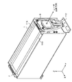
実施の形態1.
図1はこの発明にかかる直交励起型レーザ発振器の実施の形態1を示す全体斜視図であり、図2はその正面図である。図3と図4は、この発明にかかる直交励起型レーザ発振器の実施の形態1の具体的状態を示す模式図であり、図3は発振器筐体と光学基台との間に設けられた連結部材の連結状態を示す図であり、図4は発振器筐体と光学基台とを連結部材で連結した状態を模式的に示す図である。図5と図6は、発振器筐体の熱変形の様子を模式的に表す図である。また、図7〜図9は、発振器筐体が熱変形した場合の連結部材の具体的状態を示す模式図であり、図7と図8は前部光学基台付近の正面図であり、そして図9は、連結部材がZ軸回りに変形を受けた場合の様子を示す斜視図である。なお、以下の説明では、レーザ光の光軸方向をY軸とし、この光軸に垂直な高さ方向をZ軸とし、これらY軸およびZ軸に垂直な方向をX軸とする。
【0018】
発振器筐体1は、CO2ガス等のレーザ媒体ガスが封入された密閉構造を有しており、その内部には、図示されていないが、レーザビーム発生用の放電電極、レーザ媒体ガスを冷却する熱交換器、レーザ媒体ガスを循環させる送風器などが設けられている。この発振器筐体1の光軸方向の両端には、発振器筐体1の上面よりも突出するように端板18,28が設けられている。
【0019】
発振器筐体1の光軸方向の両側には、全反射鏡6を保持した後部光学基台7と、全反射鏡6と同一光軸上に部分反射鏡8を保持した前部光学基台9とが、下部に1本、上部に2本の合計3本の支持棒112〜114によって互いに平行に配置されている。そして、全反射鏡6を保持する後部光学基台7と部分反射鏡8を保持する前部光学基台9とが光共振器を構成している。なお、上部支持棒113,114は、発振器筐体1の端部に設けられている端板18,28を貫通してレーザ光の進行方向(光軸方向)に延在している。また、以下では、支持棒112〜114が3本の場合について説明するが、3本に限られる趣旨ではなく、4本以上の支持棒を有する場合でもよい。
【0020】
発振器筐体1の端板28と後部光学基台7との間および発振器筐体1の端板18と前部光学基台9との間は、それぞれベローズ10,11によって接続されており、これらベローズ10,11中を、レーザ光が貫通する。
【0021】
また、発振器筐体1の端板28と後部光学基台7との間および発振器筐体1の端板18と前部光学基台9との間は、また、連結部材22,12を介しても連結されている。この連結部材22,12によって、光学基台7,9と接続される側のベローズ10,11の中心位置が、発振器筐体1の端板28,18と接続される側のベローズ10,11の中心位置に対して、X軸方向(図2における前後方向)、Z軸方向(同じく高さ方向)、およびY軸(同じくレーザ光の光軸)まわりの回転方向の自由度を拘束し、それ以外のY軸方向、X軸まわりの回転方向およびZ軸まわりの回転方向は可動とされる。
【0022】
この連結部材12,22として、例えば、X軸方向の長さがZ軸方向の長さよりも長く、そしてY軸方向の厚さがX軸方向およびZ軸方向の長さに比べて極めて短い矩形状の板バネ12,22を用いて、発振器筐体1の端板28と後部光学基台7との間および発振器筐体1の端板18と前部光学基台9との間を連結することができる(図2および図3参照)。前部光学基台9側において、この板バネ12の上端部は、板バネ取付座14と板バネ固定板15とで挟み付けられた状態で、発振器筐体1の端板18に固定された板バネ支持板13の上端部に取り付けられる。また、板バネ12の下端部は、前部光学基台9に取り付けられた板バネ取付座16と板バネ固定板17とで挟み付けられた状態で固定される。なお、端板18、板バネ支持板13、板バネ取付座14、板バネ12および板バネ固定板15の間は、ネジ止めなどによって固定され、前部光学基台9、板バネ取付座16、板バネ12および板バネ固定板17の間もネジ止めなどによって固定される。説明は省略するが、後部光学基台7側も同様にして後部光学基台7と発振器筐体1の端板28との間に板バネ22が連結される。
【0023】
このように板バネ12,22を介して発振器筐体1と光学基台7,9とを連結することによって、前部光学基台9と後部光学基台7とによって構成される光共振器の構成は、図4に示すように発振器筐体1の上端部から板バネ12,22によって、つり下げられた状態と等しくなる。すなわち、X軸またはZ軸方向の曲げに対して変形し難く、Y軸まわりの回転方向に対する高い剛性を有する一方、Y軸方向の曲げに対しては容易に変形し、またX軸またはZ軸まわりの回転方向に対して容易に変形し得る構造を有する。
【0024】
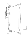
ここで、発振器筐体1は、その作動中において、レーザ媒質ガスの熱によって光軸方向(Y軸方向)に伸びるとともに、レーザ媒質ガスの温度分布によって湾曲するように熱変形する。例えば、この熱変形を受けた発振器筐体1を真上から見た場合には、図5に示されるように、発振器筐体1は元の長さよりも光軸方向(Y軸方向)に伸びるとともに、発振器筐体1の後側はその前側に比較して大きく膨張しており、Y軸に沿って湾曲するような(Z軸まわりに回転するような)変形を受けている。また、熱変形を受けた発振器筐体1を正面から見た場合には、図6に示されるように、発振器筐体1は元の長さよりも光軸方向(Y軸方向)に伸びるとともに、発振器筐体1の下側はその上側に比較して大きく膨張しており、これもY軸に沿って湾曲するような(X軸まわりに回転するような)変形を受けている。なお、図5および図6中に点線で示した矩形は、変形前の発振器筐体1の形状を示している。
【0025】
さらに、図5および図6に示されるような発振器筐体1の熱変形に伴って、発振器筐体1の両端に取り付けられたベローズ10,11の位置も変化する。一般にベローズ10,11の芯ずれ方向の剛性は軸方向の剛性に比べて非常に大きいので、ベローズ10,11の位置がずれることによって有害な反力が発生する。すなわち、この反力によって、ベローズ10,11と接続されている光共振器の構造体が変形し、二つの光学基台7,9の位置関係をずらしてしまう。
【0026】
このような発振器筐体1の両端面の平行な位置関係を崩すように作用する発振器筐体1の熱変形に対して、この実施の形態1では、二つの光学基台7,9と発振器筐体1の両端面とを板バネ22,12を介して連結したことによって、二つの光学基台7,9は発振器筐体1の熱変形による変形力を受けることがない。すなわち、図7に示されるように、発振器筐体1のY軸方向の伸びによる変形に対しては、板バネ12,22がその伸びを吸収するように変形する。そして、このときの板バネ12,22の変形によって生じる反力は非常に小さいので、この反力によって光学基台7,9が受ける力は小さい。その結果、二つの光学基台7,9の間の平行性が維持される。また、図6に示されるような発振器筐体1のYZ平面内でのY軸に沿った湾曲は、図8に示されるように、板バネ12(22)がX軸のまわりに反るような変形によって吸収される。この場合も板バネ12(22)の変形によって生じる反力は非常に小さいので、光学基台7,9に変形を与えるような大きな力は加わらない。さらに、図5に示されるような発振器筐体1のXY平面内でのY軸に沿った湾曲は、図9に示されるように、板バネ12,22がZ軸のまわりにねじれるように変形することによって吸収されるので、光学基台7,9に変形を与えるような大きな力は加わらない。
【0027】
また、板バネ12,22が、光学基台9,7側でのベローズ11,10の中心位置を、発振器筐体1の光軸方向の端面におけるベローズ11,10の中心位置に対して、X軸方向、Z軸方向およびY軸まわりの回転方向の自由度を拘束しているので、発振器筐体1の熱変形に伴うベローズ11,10の位置のずれによる軸ずれ変形は発生せず、光学基台9,7に対する有害な変形力の発生を抑えることもできる。
【0028】
なお、この実施の形態1では、板バネ12,22の上端を発振器筐体1側で支持し、その下端を光学基台7,9側で支持しているので、光学基台7,9の質量による重力方向の力が板バネ12,22に対して常時作用する。そして、この力によって板バネ12,22には、応力として引張り応力が発生する。そのために、板バネ12,22のY軸方向の厚さを薄くすることができる。すなわち、板バネ12,22の剛性をX軸方向とZ軸方向の曲げおよびY軸まわりの回転方向については極めて大きくし、Y軸方向の曲げおよびX軸とZ軸まわりの回転方向については非常に小さくすることが可能となる。
【0029】
以上で説明したように、発振器筐体1の熱による変形が生じた場合に、光共振器を構成する二つの光学基台7,9が発振器筐体1の両端面にしっかりと固定されているような構成を有する直交励起型レーザ発振器では、発振器筐体1の変形に追従して二つの光学基台7,9は変形力を受け、その結果として二つの光学基台7,9の平行性が失われてしまうが、この実施の形態1によれば、連結部材としての板バネ12,22が発振器筐体1の変形を吸収し、光学基台9,7へ変形を伝えることがないので、二つの光学基台7,9の位置関係を維持することができる。また、この実施の形態1によれば、板バネ12,22によって、ベローズ11,10の軸ずれ変形が及ぼす二つの光学基台9,7への有害な変形力を抑えることもできる。その結果、レーザ光のレーザ光軸を一定に保つことが可能となる。
【0030】
実施の形態2.
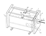
図10は、この発明にかかる直交励起型レーザ発振器の実施の形態2を示す図であり、連結部材である板バネ12(22)としてコの字型形状のものを使用する場合を示している。なお、この図10では、発振器筐体1と前部光学基台9とを連結する板バネ12’を取り付ける場合の状態を示しており、上述した実施の形態1と同一の構成要素には同一の符号を付してその説明を省略している。
【0031】
上述した実施の形態1では、X軸方向の長さがZ軸方向の長さよりも長い矩形状の板バネ12(22)を例に挙げて説明したが、この実施の形態2では、コの字型形状の板バネ12’(22’)を連結部材として使用する。
【0032】
このコの字型形状の板バネ12’は、脚部12a’,12b’をZ軸下方に向けて、そして、これらの脚部12a’,12b’でベローズ11(10)を挟むようにして配置される。すなわち、前部光学基台9側において、この板バネ12’の上端部は板バネ取付座14と板バネ固体板15とで挟み付けられた状態で、発振器筐体1の端板18に固定された板バネ支持板13の上端部に取り付けられている。また、板バネ12’の2本の脚部12a’,12b’は、それぞれ前部光学基台9に取り付けられた板バネ取付座16a’,16b’と板バネ固定板17a’,17b’とで挟み付けられた状態で固定される。ただし、板バネ取付座16a’,16b’と板バネ固定板17a’,17b’によって固定される板バネ12’の脚部12a’,12b’の位置は、ベローズ11の中心位置の高さと同じ高さとなる。
【0033】
このように、コの字型形状の板バネ12’(22’)は、実施の形態1の矩形状の板バネ12(22)と比較して、その形状と配置方法からZ軸回りの方向に変形し易いものとなっている。つまり、Z軸回りの回転方向の変形を効率的に吸収することが可能となる。
【0034】
この実施の形態2によれば、コの字型形状の板バネ12’,22’を連結部材として使用したので、板バネ12’,22’のZ軸まわりのねじり変形が容易に発生し、板バネ12’,22’の変形反力を一層小さくすることができる。その結果、発振器筐体1の熱変形による影響とそれによるベローズ10,11の軸ずれ変形による影響を、光共振器を構成する二つの光学基台7,9に与えることがない。
【0035】
実施の形態3.
図11は、この発明にかかる直交励起型レーザ発振器の実施の形態3を示す図であり、発振器筐体1と前部光学基台9との接続部分における正面図を示している。上述した実施の形態1では、板バネ12,22の上端部は発振器筐体1側に連結され、その下端部は光学基台7,9側に連結される場合を示したが、この実施の形態3では、図11に示されるように実施の形態1とは逆の場合、すなわち板バネ12,22の上端部は光学基台7,9側に連結され、その下端部は発振器筐体1側に連結される場合を示している。
【0036】
すなわち、前部光学基台9側において、この板バネ12の下端部は、板バネ取付座14と板バネ固定板15とで挟み付けられた状態で、発振器筐体1の光軸方向の側端部に固定された板バネ支持板13の上端部に取り付けられる。また、板バネ12の上端部は、前部光学基台9に取り付けられた板バネ取付座16と板バネ固定板17とで挟み付けられた状態で固定される。なお、発振器筐体1の側端部、板バネ支持板13、板バネ取付座14、板バネ12および板バネ固定板15の間は、ネジ止めなどによって固定され、前部光学基台9、板バネ取付座16、板バネ12および板バネ固定板17の間もネジ止めなどによって固定される。図示されていないが、後部光学基台7側も同様にして、板バネ22の上端部は後部光学基台7側に連結され、その下端部は発振器筐体1の端板28側に連結される。
【0037】
この実施の形態3によれば、板バネ12,22の発振器筐体1側への連結位置を、光学基台7,9側への連結位置よりも下方にする構成としたので、板バネ12,22に光学基台9,7の重力がかかり、そのために板バネ12,22の座屈を防止することができる程度に板バネ12,22の板厚を厚くする必要があるが、実施の形態1に比べて直交励起型レーザ発振器の組立構造をシンプルにすることが可能となる。
【0038】
【発明の効果】
以上説明したように、この発明による直交励起型レーザ発振器によれば、光共振器の光軸方向をY軸とし、光軸方向に垂直な高さ方向をZ軸とし、Y軸およびZ軸に垂直な方向をX軸とした場合に、光学基台側と接続されているベローズの中心位置が、発振器筐体の側端部側と接続されている前記ベローズの中心位置に対して、X軸およびZ軸方向の曲げ運動とY軸まわりの回転運動を拘束し、Y軸方向の曲げ運動とX軸およびZ軸まわりの回転運動を可能とするように、発振器筐体の光軸方向の側端部と光学基台とを連結する連結部材を備えるように構成したので、発振器筐体の熱変形やベローズの軸ずれ変形による力を吸収することができるという効果を有する。そして、二個の光学基台の位置関係(平行度、軸ずれ)は初期の状態を保つことができ、レーザ光の品質(出力、ビームモード)を安定に保つことができるという効果を有する。
【0039】
つぎの発明によれば、連結部材を板バネによって構成するようにしたので、発振器筐体の熱変形やベローズの軸ずれ変形による力を効果的に吸収することができるという効果を有する。その結果、2個の光学基台の位置関係(平行度、軸ずれ)は初期の状態を保つことができ、レーザ光の品質(出力、ビームモード)を安定に保つことができるという効果を有する。さらに、リニアベアリング等のガイド機構によって光学基台間の変形を防止する場合には、微小な変位に対して摩擦力によるスティックスリップが発生し、光学基台に有害な変形が発生してしまうが、板バネによるガイド機構を用いる場合には、摩擦力が発生しないためこのようなスティックスリップが発生することがないという効果を有する。そして、板バネによるガイド機構はリニアベアリング等のガイド機構に比べて安価に構成できるという効果を有する。
【0040】
つぎの発明によれば、連結部材をコの字型形状の板バネによって構成するようにしたので、板バネのZ軸まわりのねじり変形が容易に発生し、板バネの変形反力を一層小さくすることができるという効果を有する。その結果、発振器筐体の熱変形による影響とそれによるベローズの軸ずれ変形による影響を、光共振器を構成する二つの光学基台に与えることがない。
【0041】
つぎの発明によれば、板バネの上端部は発振器筐体の側端部側で支持され、その下端部は光学基台側で支持されるように構成したので、光学基台の質量による重力によって板バネに引張り応力が発生するために、板バネのY軸方向の厚さを薄くすることができるという効果を有する。
【0042】
つぎの発明によれば、板バネの下端部は発振器筐体の側端部側で支持され、その上端部は光学基台側で支持されるように構成したので、直交励起型レーザ発振器の組立構造をシンプルにすることができるという効果を有する。
【図面の簡単な説明】
【図1】 この発明の実施の形態1の直交励起型レーザ発振器の全体斜視図である。
【図2】 この発明の実施の形態1の直交励起型レーザ発振器の正面図である。
【図3】 この発明の実施の形態1の直交励起型レーザ発振器における連結部材の連結の様子を示す斜視図である。
【図4】 この発明の実施の形態1の直交励起型レーザ発振器における発振器筐体と光学基台との間の関係を示す模式図である。
【図5】 発振器筐体の熱変形状態を示す平面図である。
【図6】 発振器筐体の熱変形状態を示す正面図である。
【図7】 連結部材のY軸方向の曲げ変形の様子を示す図である。
【図8】 連結部材のX軸まわりの回転の変形の様子を示す図である。
【図9】 連結部材のZ軸まわりの回転の変形の様子を示す図である。
【図10】 この発明の実施の形態2の直交励起型レーザ発振器における連結部材とベローズの位置関係を示す模式図である。
【図11】 この発明の実施の形態3の直交励起型レーザ発振器の連結部材の位置関係を示す模式図である。
【図12】 直交励起型レーザ発振器の従来例を示す斜視図である。
【符号の説明】
1 発振器筐体、6 全反射鏡、7 後部光学基台、8 部分反射鏡、9 前部光学基台、10,11 ベローズ、12,12’,22,22’ 連結部材(板バネ)、13 板バネ支持板、14,16,16a’,16b’ 板バネ取付座、15,17,17a’,17b’ 板バネ固定板、18,28 端板、112〜115 支持棒。[0001]
BACKGROUND OF THE INVENTION
This invention stabilizes the quality of the laser beam output and beam mode by keeping the positional relationship such as parallelism and axial deviation of the pair of optical resonators constant even when the oscillator housing is deformed by heat. The present invention relates to an orthogonally pumped laser oscillator having a structure that can be kept at a constant level.
[0002]
[Prior art]
A gas laser oscillator generally includes a discharge tube in which a laser gas is sealed to excite a laser by discharge, and an optical resonator having two mirrors disposed on both sides of the discharge tube. When a large amount of heat is generated in the discharge tube during laser oscillation, part of the heat is transferred to the optical resonator or the base plate that supports the discharge tube and the optical resonator, and as a result, they are deformed by heat. The parallelism of the pair of optical bases constituting the resonator is misaligned, the position of the optical resonator is shifted from the axis of the oscillator housing, and the like. Also, the optical resonator itself may cause a difference in thermal expansion between structural members such as a frame rod member and an end face plate member due to a change in the outside air temperature, which may also cause a shift in the position of the optical resonator. . Such a shift in the position of the optical resonator causes a mirror alignment error, and makes the laser output and beam mode of the laser light unstable. Therefore, in order to deal with such a positional shift of the optical resonator due to the influence of heat, laser oscillators having various configurations have been proposed.
[0003]
As an invention related to a conventional laser oscillator, there is a conventional technique disclosed in Japanese Patent Laid-Open No. 2000-183425 shown in FIG. In this prior art, a front
[0004]
[Problems to be solved by the invention]
In the above-described prior art, the positional relationship between the two
[0005]
The present invention has been made in view of the above, so that even if the oscillator housing is thermally deformed, the optical resonator composed of the two optical bases arranged in parallel and the support rod is not subjected to deformation force. An object of the present invention is to obtain an orthogonally pumped laser oscillator that can be used.
[0006]
[Means for Solving the Problems]
In order to achieve the above object, an orthogonally pumped laser oscillator according to the present invention is connected in parallel to each other by an oscillator casing and at least three support rods installed on both sides of the oscillator casing and extending in the optical axis direction. An orthogonally pumped laser oscillator comprising: a pair of optical bases each supporting an optical component constituting an optical resonator; and a pair of bellows connecting between the pair of optical bases and the oscillator housing The optical axis direction of the optical resonator is the Y axis, the height direction perpendicular to the optical axis direction is the Z axis, and the direction perpendicular to the Y axis and the Z axis is the X axis, The center position of the bellows connected to the base side is bent in the X-axis and Z-axis directions and around the Y-axis with respect to the center position of the bellows connected to the side end of the oscillator housing. Constraints the rotational movement of the Y axis Bent so as to allow rotational movement about movement and X and Z axes of, characterized in that it comprises a connecting member for connecting the side end portion of the oscillator housing and the optical base.
[0007]
According to this invention, the center position of the bellows connected to the optical base side is bent in the X-axis and Z-axis directions with respect to the center position of the bellows connected to the side end portion side of the oscillator housing. The side end of the oscillator housing and the optical base are connected so that the movement and the rotational movement about the Y-axis are constrained, and the bending movement in the Y-axis direction and the rotational movement about the X-axis and the Z-axis are possible. A connecting member is provided.
[0008]
The orthogonally pumped laser oscillator according to the next invention is characterized in that, in the above invention, the connecting member is constituted by a leaf spring.
[0009]
According to this invention, the connecting member is configured by the leaf spring.
[0010]
The orthogonally pumped laser oscillator according to the next invention is characterized in that, in the above invention, the connecting member is constituted by a U-shaped plate spring.
[0011]
According to this invention, the connecting member is configured by a U-shaped plate spring.
[0012]
In the orthogonal excitation type laser oscillator according to the next invention, in the above invention, the upper end portion of the leaf spring is supported on the side end portion side of the oscillator casing, and the lower end portion thereof is supported on the optical base side. It is characterized by that.
[0013]
According to this invention, the upper end portion of the leaf spring is supported on the side end portion side of the oscillator casing, and the lower end portion thereof is supported on the optical base side.
[0014]
In the orthogonal excitation type laser oscillator according to the next invention, in the above invention, the lower end portion of the leaf spring is supported on the side end portion side of the oscillator casing, and the upper end portion is supported on the optical base side. It is characterized by that.
[0015]
According to this invention, the lower end portion of the leaf spring is supported on the side end portion side of the oscillator housing, and the upper end portion thereof is supported on the optical base side.
[0016]
DETAILED DESCRIPTION OF THE INVENTION
Exemplary embodiments of an orthogonally pumped laser oscillator according to the present invention will be explained below in detail with reference to the accompanying drawings.
[0017]
FIG. 1 is an overall perspective
[0018]
The
[0019]
On both sides of the
[0020]
The
[0021]
Further, between the
[0022]
As the connecting
[0023]
By connecting the
[0024]
Here, during operation, the
[0025]
Further, with the thermal deformation of the
[0026]
With respect to the thermal deformation of the
[0027]
Further, the
[0028]
In the first embodiment, the upper ends of the
[0029]
As described above, when the
[0030]
Embodiment 2. FIG.
FIG. 10 is a diagram showing a second embodiment of the orthogonal excitation type laser oscillator according to the present invention, and shows a case where a U-shaped one is used as the leaf spring 12 (22) which is a connecting member. . FIG. 10 shows a state in which a
[0031]
In the first embodiment described above, the rectangular leaf spring 12 (22) whose length in the X-axis direction is longer than the length in the Z-axis direction has been described as an example. A letter-shaped plate spring 12 '(22') is used as a connecting member.
[0032]
The U-shaped plate spring 12 'is arranged so that the
[0033]
As described above, the
[0034]
According to the second embodiment, since the U-shaped plate springs 12 ′ and 22 ′ are used as the connecting members, the torsional deformation around the Z axis of the plate springs 12 ′ and 22 ′ easily occurs. The deformation reaction force of the leaf springs 12 'and 22' can be further reduced. As a result, the two
[0035]
Embodiment 3 FIG.
FIG. 11 is a diagram showing a third embodiment of the orthogonal excitation type laser oscillator according to the present invention, and shows a front view of a connection portion between the
[0036]
That is, on the front
[0037]
According to the third embodiment, the connection position of the
[0038]
【The invention's effect】
As described above, according to the orthogonally pumped laser oscillator according to the present invention, the optical axis direction of the optical resonator is the Y axis, the height direction perpendicular to the optical axis direction is the Z axis, and the Y axis and the Z axis are When the vertical direction is the X axis, the center position of the bellows connected to the optical base side is the X axis with respect to the center position of the bellows connected to the side end side of the oscillator housing. And the optical axis side of the oscillator housing so that the bending motion in the Z-axis direction and the rotational motion about the Y-axis are constrained, and the bending motion in the Y-axis direction and the rotational motion around the X-axis and the Z-axis are enabled. Since the connecting member for connecting the end portion and the optical base is provided, there is an effect that it is possible to absorb a force due to thermal deformation of the oscillator housing and axial deformation of the bellows. The positional relationship (parallelism, axial deviation) between the two optical bases can maintain the initial state, and the laser beam quality (output, beam mode) can be maintained stably.
[0039]
According to the next invention, since the connecting member is constituted by the leaf spring, it is possible to effectively absorb the force due to the thermal deformation of the oscillator housing and the axial displacement of the bellows. As a result, the positional relationship (parallelism, axial deviation) of the two optical bases can be maintained in the initial state, and the quality of the laser beam (output, beam mode) can be stably maintained. . Furthermore, when the deformation between the optical bases is prevented by a guide mechanism such as a linear bearing, stick slip due to a frictional force is generated with respect to a minute displacement, and harmful deformation occurs in the optical base. In the case of using a guide mechanism with a leaf spring, since a frictional force is not generated, there is an effect that such stick-slip does not occur. And the guide mechanism by a leaf | plate spring has the effect that it can comprise at low cost compared with guide mechanisms, such as a linear bearing.
[0040]
According to the next invention, since the connecting member is constituted by the U-shaped plate spring, the torsional deformation around the Z axis of the plate spring easily occurs, and the deformation reaction force of the plate spring is further reduced. It has the effect that it can be done. As a result, the influence of thermal deformation of the oscillator housing and the influence of the axial displacement of the bellows are not given to the two optical bases constituting the optical resonator.
[0041]
According to the next invention, the upper end portion of the leaf spring is supported on the side end portion side of the oscillator housing, and the lower end portion thereof is supported on the optical base side. As a result, tensile stress is generated in the leaf spring, so that the thickness of the leaf spring in the Y-axis direction can be reduced.
[0042]
According to the next invention, the lower end portion of the leaf spring is supported on the side end portion side of the oscillator housing, and the upper end portion is supported on the optical base side. The structure can be simplified.
[Brief description of the drawings]
FIG. 1 is an overall perspective view of an orthogonally pumped laser oscillator according to a first embodiment of the present invention.
FIG. 2 is a front view of the orthogonal pumping laser oscillator according to the first embodiment of the present invention.
FIG. 3 is a perspective view showing a state of connection of connection members in the orthogonal excitation laser oscillator according to the first embodiment of the present invention.
FIG. 4 is a schematic diagram showing a relationship between an oscillator housing and an optical base in the orthogonal excitation laser oscillator according to the first embodiment of the present invention.
FIG. 5 is a plan view showing a state of thermal deformation of the oscillator housing.
FIG. 6 is a front view showing a state of thermal deformation of the oscillator housing.
FIG. 7 is a diagram showing a bending deformation state of a connecting member in the Y-axis direction.
FIG. 8 is a diagram showing a state of deformation of rotation around the X axis of a connecting member.
FIG. 9 is a diagram showing a state of deformation of rotation around a Z-axis of a connecting member.
FIG. 10 is a schematic diagram showing a positional relationship between a connecting member and a bellows in the orthogonal excitation laser oscillator according to the second embodiment of the present invention.
FIG. 11 is a schematic diagram showing the positional relationship of connecting members of an orthogonal excitation laser oscillator according to a third embodiment of the present invention.
FIG. 12 is a perspective view showing a conventional example of an orthogonal excitation laser oscillator.
[Explanation of symbols]
DESCRIPTION OF
Claims (5)
前記光共振器の光軸方向をY軸とし、前記光軸方向に垂直な高さ方向をZ軸とし、前記Y軸およびZ軸に垂直な方向をX軸とした場合、
前記光学基台側と接続されている前記ベローズの中心位置が、前記発振器筐体の側端部側と接続されている前記ベローズの中心位置に対して、X軸およびZ軸方向の曲げ運動とY軸まわりの回転運動を拘束し、Y軸方向の曲げ運動とX軸およびZ軸まわりの回転運動を可能とするように、前記発振器筐体の側端部と前記光学基台とを連結する連結部材を備えることを特徴とする直交励起型レーザ発振器。A pair of optical elements that respectively support an optical component constituting an optical resonator and are connected to each other in parallel by at least three support rods that are installed on both sides of the oscillator casing and extend in the optical axis direction. In a quadrature excitation laser oscillator comprising a base and a pair of bellows connecting the pair of optical bases and the oscillator housing,
When the optical axis direction of the optical resonator is the Y axis, the height direction perpendicular to the optical axis direction is the Z axis, and the direction perpendicular to the Y axis and the Z axis is the X axis,
Bending motion in the X-axis and Z-axis directions with respect to the center position of the bellows connected to the side end portion side of the oscillator housing with respect to the center position of the bellows connected to the optical base side The side end of the oscillator housing and the optical base are coupled so as to constrain the rotational movement about the Y axis and enable the bending movement in the Y-axis direction and the rotational movement about the X-axis and the Z-axis. An orthogonal excitation type laser oscillator comprising a connecting member.
Priority Applications (2)
| Application Number | Priority Date | Filing Date | Title |
|---|---|---|---|
| JP2002109694A JP3768455B2 (en) | 2002-04-11 | 2002-04-11 | Orthogonal excitation laser oscillator |
| US10/278,932 US6920170B2 (en) | 2002-04-11 | 2002-10-24 | Orthogonally excited-type laser oscillator |
Applications Claiming Priority (1)
| Application Number | Priority Date | Filing Date | Title |
|---|---|---|---|
| JP2002109694A JP3768455B2 (en) | 2002-04-11 | 2002-04-11 | Orthogonal excitation laser oscillator |
Publications (2)
| Publication Number | Publication Date |
|---|---|
| JP2003304015A JP2003304015A (en) | 2003-10-24 |
| JP3768455B2 true JP3768455B2 (en) | 2006-04-19 |
Family
ID=28786600
Family Applications (1)
| Application Number | Title | Priority Date | Filing Date |
|---|---|---|---|
| JP2002109694A Expired - Lifetime JP3768455B2 (en) | 2002-04-11 | 2002-04-11 | Orthogonal excitation laser oscillator |
Country Status (2)
| Country | Link |
|---|---|
| US (1) | US6920170B2 (en) |
| JP (1) | JP3768455B2 (en) |
Families Citing this family (7)
| Publication number | Priority date | Publication date | Assignee | Title |
|---|---|---|---|---|
| WO2008136073A1 (en) * | 2007-04-20 | 2008-11-13 | Mitsubishi Electric Corporation | Laser oscillator |
| JP4565045B2 (en) * | 2008-07-17 | 2010-10-20 | ファナック株式会社 | Gas laser resonator |
| CN102439279B (en) | 2009-05-21 | 2014-06-18 | 丰田自动车株式会社 | Air-fuel ratio control device for internal-combustion engine |
| CN105075035B (en) | 2013-03-26 | 2017-12-29 | 三菱电机株式会社 | Gas laser device |
| CN104167658A (en) * | 2014-08-29 | 2014-11-26 | 苏州市华宁机械制造有限公司 | Resonant cavity device of quick axial flow laser |
| CN105846298B (en) * | 2016-06-07 | 2018-06-26 | 中国科学院长春光学精密机械与物理研究所 | A kind of optical resonator |
| JP2022014176A (en) * | 2020-07-06 | 2022-01-19 | 住友重機械工業株式会社 | Laser device |
Family Cites Families (6)
| Publication number | Priority date | Publication date | Assignee | Title |
|---|---|---|---|---|
| JPS61199685A (en) | 1985-03-01 | 1986-09-04 | Mitsubishi Electric Corp | Laser oscillator |
| JPS6350083A (en) | 1986-08-20 | 1988-03-02 | Matsushita Electric Ind Co Ltd | Gas laser device |
| JPH05206544A (en) | 1992-01-28 | 1993-08-13 | Mitsubishi Electric Corp | Laser oscillator |
| JPH07111352A (en) | 1993-10-12 | 1995-04-25 | Toshiba Corp | Laser oscillator |
| JPH07307506A (en) * | 1994-05-16 | 1995-11-21 | Mitsubishi Electric Corp | Laser oscillator |
| JP3399865B2 (en) | 1998-12-16 | 2003-04-21 | 三菱電機株式会社 | Optical base support structure of orthogonally pumped laser oscillator |
-
2002
- 2002-04-11 JP JP2002109694A patent/JP3768455B2/en not_active Expired - Lifetime
- 2002-10-24 US US10/278,932 patent/US6920170B2/en not_active Expired - Lifetime
Also Published As
| Publication number | Publication date |
|---|---|
| US20030193985A1 (en) | 2003-10-16 |
| JP2003304015A (en) | 2003-10-24 |
| US6920170B2 (en) | 2005-07-19 |
Similar Documents
| Publication | Publication Date | Title |
|---|---|---|
| JP3768455B2 (en) | Orthogonal excitation laser oscillator | |
| JP4565045B2 (en) | Gas laser resonator | |
| JPH07307506A (en) | Laser oscillator | |
| JP4958973B2 (en) | Laser oscillator | |
| JP3835116B2 (en) | Laser oscillator | |
| JP3665039B2 (en) | Orthogonal excitation laser oscillator | |
| JP2007329260A (en) | Laser oscillation device | |
| JP3399865B2 (en) | Optical base support structure of orthogonally pumped laser oscillator | |
| RU2299505C1 (en) | Laser resonator | |
| WO2004105200A1 (en) | Laser transmitter | |
| JPS61199685A (en) | Laser oscillator | |
| JP3731117B2 (en) | Laser oscillator | |
| JPS6350083A (en) | Gas laser device | |
| JPH10163549A (en) | Laser light source device and support structure thereof | |
| JPS6024082A (en) | Laser oscillator | |
| JP3594938B2 (en) | Gas laser oscillator | |
| JPH07111352A (en) | Laser oscillator | |
| JP2003046164A (en) | Orthogonal excited laser oscillator | |
| JP2681319B2 (en) | Laser oscillator | |
| JPH0587034B2 (en) | ||
| JP2022014176A (en) | Laser device | |
| JPH0221678A (en) | Axial-flow type gas laser | |
| JP2003037315A (en) | Orthogonal pumping laser oscillator | |
| JPS6348875A (en) | Laser oscillator | |
| JPS61188984A (en) | Gas laser oscillator |
Legal Events
| Date | Code | Title | Description |
|---|---|---|---|
| A977 | Report on retrieval |
Free format text: JAPANESE INTERMEDIATE CODE: A971007 Effective date: 20051128 |
|
| TRDD | Decision of grant or rejection written | ||
| A01 | Written decision to grant a patent or to grant a registration (utility model) |
Free format text: JAPANESE INTERMEDIATE CODE: A01 Effective date: 20060131 |
|
| A61 | First payment of annual fees (during grant procedure) |
Free format text: JAPANESE INTERMEDIATE CODE: A61 Effective date: 20060201 |
|
| R150 | Certificate of patent or registration of utility model |
Ref document number: 3768455 Country of ref document: JP Free format text: JAPANESE INTERMEDIATE CODE: R150 Free format text: JAPANESE INTERMEDIATE CODE: R150 |
|
| FPAY | Renewal fee payment (event date is renewal date of database) |
Free format text: PAYMENT UNTIL: 20100210 Year of fee payment: 4 |
|
| FPAY | Renewal fee payment (event date is renewal date of database) |
Free format text: PAYMENT UNTIL: 20100210 Year of fee payment: 4 |
|
| FPAY | Renewal fee payment (event date is renewal date of database) |
Free format text: PAYMENT UNTIL: 20110210 Year of fee payment: 5 |
|
| FPAY | Renewal fee payment (event date is renewal date of database) |
Free format text: PAYMENT UNTIL: 20120210 Year of fee payment: 6 |
|
| FPAY | Renewal fee payment (event date is renewal date of database) |
Free format text: PAYMENT UNTIL: 20130210 Year of fee payment: 7 |
|
| FPAY | Renewal fee payment (event date is renewal date of database) |
Free format text: PAYMENT UNTIL: 20130210 Year of fee payment: 7 |
|
| FPAY | Renewal fee payment (event date is renewal date of database) |
Free format text: PAYMENT UNTIL: 20140210 Year of fee payment: 8 |
|
| R250 | Receipt of annual fees |
Free format text: JAPANESE INTERMEDIATE CODE: R250 |
|
| R250 | Receipt of annual fees |
Free format text: JAPANESE INTERMEDIATE CODE: R250 |
|
| R250 | Receipt of annual fees |
Free format text: JAPANESE INTERMEDIATE CODE: R250 |
|
| R250 | Receipt of annual fees |
Free format text: JAPANESE INTERMEDIATE CODE: R250 |
|
| R250 | Receipt of annual fees |
Free format text: JAPANESE INTERMEDIATE CODE: R250 |
|
| R250 | Receipt of annual fees |
Free format text: JAPANESE INTERMEDIATE CODE: R250 |
|
| R250 | Receipt of annual fees |
Free format text: JAPANESE INTERMEDIATE CODE: R250 |
|
| EXPY | Cancellation because of completion of term |