JP3766230B2 - Excimer laser equipment - Google Patents
Excimer laser equipment Download PDFInfo
- Publication number
- JP3766230B2 JP3766230B2 JP11397299A JP11397299A JP3766230B2 JP 3766230 B2 JP3766230 B2 JP 3766230B2 JP 11397299 A JP11397299 A JP 11397299A JP 11397299 A JP11397299 A JP 11397299A JP 3766230 B2 JP3766230 B2 JP 3766230B2
- Authority
- JP
- Japan
- Prior art keywords
- excimer laser
- laser device
- fan
- coil
- motor
- Prior art date
- Legal status (The legal status is an assumption and is not a legal conclusion. Google has not performed a legal analysis and makes no representation as to the accuracy of the status listed.)
- Expired - Lifetime
Links
Images


Classifications
-
- F—MECHANICAL ENGINEERING; LIGHTING; HEATING; WEAPONS; BLASTING
- F16—ENGINEERING ELEMENTS AND UNITS; GENERAL MEASURES FOR PRODUCING AND MAINTAINING EFFECTIVE FUNCTIONING OF MACHINES OR INSTALLATIONS; THERMAL INSULATION IN GENERAL
- F16C—SHAFTS; FLEXIBLE SHAFTS; ELEMENTS OR CRANKSHAFT MECHANISMS; ROTARY BODIES OTHER THAN GEARING ELEMENTS; BEARINGS
- F16C32/00—Bearings not otherwise provided for
- F16C32/04—Bearings not otherwise provided for using magnetic or electric supporting means
- F16C32/0406—Magnetic bearings
- F16C32/044—Active magnetic bearings
- F16C32/047—Details of housings; Mounting of active magnetic bearings
-
- H—ELECTRICITY
- H01—ELECTRIC ELEMENTS
- H01S—DEVICES USING THE PROCESS OF LIGHT AMPLIFICATION BY STIMULATED EMISSION OF RADIATION [LASER] TO AMPLIFY OR GENERATE LIGHT; DEVICES USING STIMULATED EMISSION OF ELECTROMAGNETIC RADIATION IN WAVE RANGES OTHER THAN OPTICAL
- H01S3/00—Lasers, i.e. devices using stimulated emission of electromagnetic radiation in the infrared, visible or ultraviolet wave range
- H01S3/02—Constructional details
- H01S3/03—Constructional details of gas laser discharge tubes
- H01S3/036—Means for obtaining or maintaining the desired gas pressure within the tube, e.g. by gettering, replenishing; Means for circulating the gas, e.g. for equalising the pressure within the tube
-
- H—ELECTRICITY
- H01—ELECTRIC ELEMENTS
- H01S—DEVICES USING THE PROCESS OF LIGHT AMPLIFICATION BY STIMULATED EMISSION OF RADIATION [LASER] TO AMPLIFY OR GENERATE LIGHT; DEVICES USING STIMULATED EMISSION OF ELECTROMAGNETIC RADIATION IN WAVE RANGES OTHER THAN OPTICAL
- H01S3/00—Lasers, i.e. devices using stimulated emission of electromagnetic radiation in the infrared, visible or ultraviolet wave range
- H01S3/02—Constructional details
- H01S3/03—Constructional details of gas laser discharge tubes
- H01S3/038—Electrodes, e.g. special shape, configuration or composition
- H01S3/0388—Compositions, materials or coatings
-
- H—ELECTRICITY
- H01—ELECTRIC ELEMENTS
- H01S—DEVICES USING THE PROCESS OF LIGHT AMPLIFICATION BY STIMULATED EMISSION OF RADIATION [LASER] TO AMPLIFY OR GENERATE LIGHT; DEVICES USING STIMULATED EMISSION OF ELECTROMAGNETIC RADIATION IN WAVE RANGES OTHER THAN OPTICAL
- H01S3/00—Lasers, i.e. devices using stimulated emission of electromagnetic radiation in the infrared, visible or ultraviolet wave range
- H01S3/14—Lasers, i.e. devices using stimulated emission of electromagnetic radiation in the infrared, visible or ultraviolet wave range characterised by the material used as the active medium
- H01S3/22—Gases
- H01S3/223—Gases the active gas being polyatomic, i.e. containing two or more atoms
- H01S3/225—Gases the active gas being polyatomic, i.e. containing two or more atoms comprising an excimer or exciplex
Description
【0001】
【発明の属する技術分野】
本発明は、エキシマレーザ装置に関し、特にレーザガス流を作り出すファンの回転数を検出し、該ファンの回転数を一定に制御する制御手段を具備するエキシマレーザ装置に関するものである。
【0002】
【従来の技術】
図8は従来のエキシマレーザ装置の概略構成を示す図である。従来のエキシマレーザ装置では、図示するように、レーザガスが封入されたレーザ容器101の内部に、レーザガスを予備電離する予備電離電極(図示せず)と、レーザ光の発振を可能にする放電を得るための一対の主放電電極102、102とが配置されている。更にレーザ容器101内には、一対の主放電電極102、102の間に高速のガス流れを作り出すための貫流ファン103が配置されている。
【0003】
貫流ファン103は両端部から突出する回転軸104を有していて、該回転軸104はレーザ容器101の両側に備えられた複数のラジアル磁気軸受106、107、108と、アキシャル磁気軸受109で回転自在に支持されている。そしてモータ110は貫流ファン103の回転軸104へ回転動力を与える。また、レーザ容器101には、レーザ光を取り出すための窓105、105が設けられている。
【0004】
上記構造のエキシマレーザ装置では、レーザガス内に反応性の高いハロゲンガス、例えばフッ素を含んでいるので、レーザ容器101内では様々な化学変化が生じ、HFやCF4等の不純物が発生する。この不純物によってレーザガスが劣化し、レーザ光の性能が低下するという問題があった。
【0005】
また、レーザ光の平均出力数十W以上のエキシマレーザを実現するためには、主放電電極102、102において、数kHzの高繰返し放電が必要不可欠である。この高繰返し放電により主放電電極102、102は短時間に摩耗してレーザ光の性能が低下するので、長期間安定したレーザ光を得ることができないという問題があった。
【0006】
そこで、上記問題の解決手段として、前記エキシマレーザ装置では、主放電電極102、102間に印加する放電電圧及びレーザガスの封入圧力を制御してレーザ光の性能を一定レベル以上に長時間維持するようにしている。
【0007】
【発明が解決しようとする課題】
しかしながら、上記のようなエキシマレーザ装置では、レーザガスの封入圧力が変化することによって貫流ファン103への負荷が変化し、貫流ファン103の回転数が変化するという問題があった。即ち、レーザガスの封入圧力が増すと貫流ファン103への負荷が増大することによって誘導型のモータ110の滑りが増し貫流ファン103の回転数が低下する。該回転数が低下すると、主放電電極102、102のレーザガスの流速が低下するので、高繰返し発振運転が行なえなくなるという問題があった。
【0008】
上記問題を解決するため、予め貫流ファン103の回転数をモータ110の滑りによる低下分が相殺されるように高速回転側へ設定しておく方法があるが、この方法はレーザガス圧が低圧の場合に、貫流ファン103の消費動力が増大する問題がある(貫流ファン103の消費動力は回転数の3乗に比例する)。また、滑りが生じない同期モータを使用する方法があるが、この方法はモータの構造が複雑になり、価格も高価になるという問題がある。
【0009】
本発明は上述の点に鑑みてなされたもので、レーザ容器内に封入されたレーザガスの圧力が変化してもファンの回転数を一定に維持し、主放電電極間のレーザガス流を一定にでき、レーザガスの封入圧力が変化しても高繰返し発振運転を行なえると共に、消費動力の少ないエキシマレーザ装置を提供することを目的とする。
【0010】
【課題を解決するための手段】
上記課題を解決するため請求項1に記載の発明は、レーザガスを封入するレーザ容器と、該レーザ容器内に配置され、高繰返し頻度でレーザガスを励起し放電を発生させるための一対の主放電電極と、該一対の主放電電極間に高速レーザガスの流れを作り出すファンと、該ファンの回転軸を回転自在に支持する軸受と、該ファンを駆動するモータと、該ファンの回転数を検出するための回転数検出手段、該回転数検出手段で検出された該ファン の回転数に基づいて、該モータへ供給する電圧及び周波数の一方若しくは両方を制御することにより、該ファンの回転数を一定に制御する制御手段を備えたエキシマレーザ装置において、回転数検出手段は、ファンの回転軸に固着された磁性材料からなり、レーザ容器に連通する気密空間に配置された円板と、該レーザ容器の外側で該円板と対向する位置にその間にキャンを介在して配置された磁性体とを具備することを特徴とする。
【0011】
請求項2に記載の発明は、請求項1に記載のエキシマレーザ装置において、円板は1個又は複数個のスリットを有することを特徴とする。
【0012】
請求項3に記載の発明は、請求項2に記載のエキシマレーザ装置において、磁性体の幅はスリットの幅より小さいことを特徴とする。
【0013】
請求項4に記載の発明は、請求項1に記載のエキシマレーザ装置において、磁性体にコイルを取り付け、円板の回転により前記コイルに誘導される起電力からファンの回転数を検出することを特徴とする。
【0014】
請求項5に記載の発明は、請求項1に記載のエキシマレーザ装置において、磁性体はコイルを取付けたU型磁性体であることを特徴とする。
【0015】
請求項6に記載の発明は、請求項1に記載のエキシマレーザ装置において、円板はパーマロイで作られていることを特徴とする。
【0016】
請求項7に記載の発明は、請求項1に記載のエキシマレーザ装置において、円板はPCパーマロイで作られていることを特徴とする。
【0017】
請求項8に記載の発明は、請求項1に記載のエキシマレーザ装置において、円板は直径方向に対向する一対のスリットを有することを特徴とする。
【0018】
請求項9に記載の発明は、請求項1に記載のエキシマレーザ装置において、円板は直径方向に対向する偶数個のスリットを有することを特徴とする。
【0019】
請求項10に記載の発明は、請求項1に記載のエキシマレーザ装置において、モータは誘導モータであることを特徴とする。
【0020】
請求項11に記載の発明は、請求項1に記載のエキシマレーザ装置において、磁性体の一部若しくは全体が永久磁石で構成されていることを特徴とする。
【0021】
上記のように制御手段で、回転数検出手段で検出したファン回転数からモータへの電圧及び周波数の一方若しくは両方を制御し、該ファンの回転数を一定に制御するから、レーザガスの封入圧力に無関係にファンの回転数を一定にでき、安定した高繰返し発振運転が行なえるエキシマレーザ装置を提供できる。また、モータを常に効率よく動作させるため、ファンの消費電力を低減できる。
【0022】
ファンの回転数を検出する回転数検出手段を上記のようにファンの回転軸に固着された磁性材料からなり、レーザ容器に連通する気密空間に配置された円板と、該レーザ容器の外側で該円板と対向する位置にその間にキャンを介在して配置された磁性体とを具備する構成とすることにより、ファンの回転数を正確に検出することができる。また、コイルを取り付けた磁性体をキャンを挟んでレーザ容器外に配置したので、レーザガスに対して耐腐食性の乏しいコイル等がレーザガスに曝されることなく、且つレーザガスを劣化させることもない。
【0023】
コイルを取り付ける磁性体の一部若しくは全体を永久磁石で構成することにより、磁性体と円板で形成される磁気回路の磁束密度が増すので、コイルに発生する誘導起電力が大きくなり、ファンの回転数の検出性能が高まる。また、磁束を形成するコイルへのバイアス電流も低減、若しくは不要にできるので、回路の簡略化、省電力化が達成できる。
【0024】
【発明の実施の形態】
以下、本発明の実施の形態例を図面に基づいて説明する。図1は本発明に係るエキシマレーザ装置の構成例を示す図で、図2は図1のA部分の詳細を示す図である。図1及び図2を用いて本発明に係るエキシマレーザ装置の構成を説明する。
【0025】
レーザガスが封入されたレーザ容器1の内部に、レーザガスを予備電離する予備電離電極(図示せず)と、レーザ光の発振を可能にする放電を得るための一対の主放電電極2、2とが配置されている。更にレーザ容器1内には、一対の主放電電極2、2の間に高速のガス流を作り出すための貫流ファン3が配置されている。
【0026】
レーザ光の発振は、一対の主放電電極2、2の間に高電圧を印加することによってレーザ励起放電が行われて得られる。発生したレーザ光はレーザ容器1の側壁に設けられた窓5、5を経由してレーザ容器1の外部へ取り出される。レーザ励起放電が行われると、一対の主放電電極2、2間にあるレーザガスは劣化により放電特性が悪くなり、繰返し発振が行えなくなる。このため貫流ファン3にて、レーザ容器1内のレーザガスを循環させて、放電ごとに一対の主放電電極2、2間のレーザガスを入れ替えることにより、安定した繰返し発振を行っている。
【0027】
貫流ファン3は、内部を貫通し両端部から突出する回転軸4を有している。該回転軸4は、レーザ容器1の両端部に設けられた軸受ハウジング6、モータハウジング7に収容されたラジアル磁気軸受8、9、10及びアキシャル磁気軸受11にて非接触で回転自在に支持されている。そして、モータ12は貫流ファン3の回転軸4に回転動力を与える。
【0028】
貫流ファン3の回転軸4の軸受ハウジング6側の軸端部には、アキシャル変位センサターゲット11dとスリット付円板13が固着され、レーザ容器1内に連通した気密空間内に配置されている。ここで、アキシャル変位センサターゲット11d及びスリット付円板13を構成する磁性材料としては、レーザガス中に含まれるフッ素に対して耐腐食性が良好なパーマロイ(30〜80%Niを含むFe−Ni合金)を使用している。
【0029】
図3はパーマロイのフッ素に対する耐腐食性試験の結果を示す図である。図示するようにパーマロイは、Ni含有率が多いほど耐腐食性が良好であり、Ni含有率80%のPCパーマロイ(JIS C2531)では、オーステナイト系ステンレス鋼SUS316Lとほぼ同様の耐腐食性を示しているので、PCパーマロイを用いるのがよい。
【0030】
一方、軸受ハウジング6には、アキシャル変位センサ11a及びコイル14が取り付けられたU形磁性体15が、アキシャル変位センサターゲット11d及びスリット付円板13と対向する位置に配置されており、ガスに接触する面にSUS316L等のオーステナイト系ステンレス鋼で構成された薄肉円筒状のキャン16を溶接等により固着している。これにより、アキシャル変位センサ11a及びコイル14が取り付けられたU形磁性体15は気密容器外に配置されるので、レーザガスに対して耐腐食性の乏しいコイル14等をレーザガスの接触部より除去することができる。また、U形磁性体15は、永久磁石15aとヨーク15bによって構成される(図4参照)。
【0031】
アキシャル磁気軸受11の右電磁石11bと左電磁石11cは、互いに対向する位置で軸受ハウジング6内に収容される。右電磁石11bと左電磁石11cはレーザガスと接する位置に配置されるが、飽和磁束密度の大きい磁性材料で構成することが望ましいので、パーマロイの中で最も飽和磁束密度が大きいPBパーマロイをコアに使用している。そして、コアに設けられたコイル溝へ電磁石コイルを挿入して、コイル部へレーザガスが接しないようにSUS316L等のオーステナイト系ステンレス鋼で構成された薄肉円板状のキャン17、17を溶接等により固着している。そして、右電磁石11b及び左電磁石11cのコアのレーザガスが接触する面には耐腐食処理(例えば、Niコーティング)を施す。RBパーマロイは、表面にNiメッキを施すことにより、PCパーマロイと同様の耐腐食性を持たせることができた(図3参照)。
【0032】
ラジアル磁気軸受8の変位センサ8a及び電磁石8bは軸受ハウジング6へ収容されており、変位センサ8a及び電磁石8bの内周面に、SUS16L等のオーステナイト系ステンレス鋼で構成された薄肉円筒状のキャン18を挿入し両端を溶接等により固着している。上記構造としたので、レーザガスに対して耐腐食性の乏しいけい素鋼板や銅線コイルから構成される変位センサ8a及び電磁石8bが、レーザガスと接することがない。よって、レーザガスによる腐食を防止できるとともに、レーザガスを汚染することもなくなる。
【0033】
一方、貫流ファン3の回転軸4にはラジアル磁気軸受8の変位センサターゲット8c、電磁石ターゲット8d、アキシャル磁気軸受11の電磁石ターゲット11eが固着され、各磁気軸受の変位センサ8a及び電磁石8b、右電磁石11b、左電磁石11cと対向する気密空間内に配置される。
【0034】
ここで、ラジアル磁気軸受8の変位センサターゲット8c、電磁石ターゲット8d及びアキシャル磁気軸受11の電磁石ターゲット11eを構成する磁性材料としては、レーザガス中に含まれるフッ素に対して耐腐食性が良好なパーマロイ(30〜80%Niを含むFe−Ni合金)を使用している。
【0035】
また、ラジアル磁気軸受8の変位センサターゲット8c及び電磁石ターゲット8dには、回転によって生じる磁界変化によって渦電流損失が発生する。この渦電流損失を低減するため、通常は薄板を積層した構造をとる。しかしながら、積層した薄板の間にガス溜りができレーザガスを汚染する。積層表面に均一で密着性の高いNiメッキが施せない等の問題が生じる場合は、変位センサターゲット8c及び電磁石ターゲット8dをパーマロイの一体材料で形成すると良い。なお、アキシャル磁気軸受11の電磁石ターゲット11eは、回転により磁界が変化することがないので、パーマロイの一体材料で形成する。
【0036】
モータハウジング7にはラジアル磁気軸受9の変位センサ9a、電磁石9b及びモータ12のモータステータ12a及びラジアル磁気軸受10の変位センサ10a、電磁石10bがそれぞれ相対位置が決まった状態で配置されている。そして、モータハウジング7の内周面には、SUS316L等のステンレス鋼で構成された薄肉円筒状のキャン19を挿入し、両端を溶接等により固着している。上記構造とすることによって、レーザガスに対して耐腐食性の乏しいけい素鋼板や銅線コイルからなる磁気軸受の変位センサ9a、10a、電磁石9b、10b及びモータステータ12aをレーザガスの接ガス部から除去することができた。
【0037】
また、モータハウジング7の外周部には、モータ12が発生する数100Wの熱損失を吸熱する水冷ジャケット22を設けた。更に、モータステータ12aのコイル部には、コイルの抵抗により発生する熱の冷却を効率よく行うため絶縁材料を含浸した。これにより、コイルの放熱性能が上がり、モータの焼損を防止している。
【0038】
一方、貫流ファン3の回転軸4には、ラジアル磁気軸受9の変位センサターゲット9c、電磁石ターゲット9dとモータ12のモータロータ12bとラジアル磁気軸受10の変位センサターゲット10c、電磁石ターゲット10dが、各磁気軸受の変位センサ9a、10a、電磁石9b、10b及びモータステータ12aと対向する気密空間内に配置される。ここで、変位センサターゲット9c、10c及び電磁石ターゲット9d、10dを構成する磁性材料としては、ラジアル磁気軸受8の変位センサターゲット8c及び電磁石ターゲット8dと同様にパーマロイ(30〜80%Niを含むFe−Ni合金)を使用している。
【0039】
また、モータ12のモータロータ12bは、積層したけい素鋼板とアルミニウムの複合材からなるので表面に耐腐食処理として好適なNiメッキを密着性良く、均一に施工できない。よって、モータロータ12bの外周面にキャン20を取付け、側板21、21と溶接等により固着し、更に側板21、21と貫流ファン3の回転軸4を溶接等により固着することにより気密空間を形成し、レーザガスに接することをなくしている。キャン20及び側板21の材料は、SUS316L等のオーステナイト系ステンレス鋼で構成する。
【0040】
制御回路30は、内部に回転数検出回路31と演算回路32とインバータ33を具備している。コイル14は回転数検出回路31に接続される。また、インバータ33は、モータ12のモータステータ12aの巻線と接続して駆動電力を供給するようになっている。
【0041】
次に、図4を用いて、貫流ファン3の回転を検出する動作を説明する。図4に示す如く、スリット付円板13には、スリット13aが180°対向して2箇所設けられている。スリット13aは回転体のアンバランスの原因となるので、偶数単位で設けることが望ましい。そして、スリット付円板13に対向する位置にはコイル14が取り付けられたU形磁性体15が配置されている。ここで、U形磁性体15の幅はスリット付円板13のスリット13aの幅より小さくなっている。
【0042】
スリット付円板13に設けられたスリット13aとコイル14が取付けられたU形磁性体15の相対的位置が図5(a)、(b)の位置にあるとき、スリット付円板13とコイル14が取り付けられたU形磁性体15で形成する磁気回路の磁束ф1は、概略式(1)となる。
【0043】
ф1=NI/{(l1/μ1S)+(l2/μ2S)+(2x/μ0S)} (1)
N:コイル14の巻数、I:コイル14の電流、l1:U形磁性体15の磁路長、l2:円板の磁路長、S:磁路断面積、X:はスリット付円板13とU形磁性体15の断面積{図4(c)参照}、μ1:U形磁性体15の透磁率、μ2:スリット付円板13の透磁率、μ0:真空の透磁率、
【0044】
次に、スリット付円板13に設けられたスリット13aとコイル14が取り付けられたU形磁性体15の相対的位置が図5(d)、(e)の位置にあるときの磁束ф2は、概略式(2)となる。
【0045】
ф2=NI/{(l2/μ1S)+(l’/μ0S)} (2)
l’:空間の仮想自磁路長{図4(f)参照}
【0046】
上記磁束ф1と磁束ф2との磁束差Δфと、スリット付円板13が回転することによって磁束ф1から磁束ф2へ変化する時間tによりU形磁性体15に取り付けられたコイル14には、
e=NΔф/t (3)
の誘導起電力が発生する。
【0047】
即ち、スリット付円板13が回転することにより、スリット付円板13とコイル14が取り付けられたU形磁性体15にて形成された磁路の磁束がスリット付円板13のスリット13aを通過するときにф1→ф2→ф1へと変化するので、コイル14に起電力が発生する。例えば、スリット付円板13が3000rpmにて回転している場合のコイル14に発生する起電力の時間変化の模式を図5に示す。図5に示すように、誘導起電力はスリット13aを通過する際にピークが発生する。このピークを回転数検出回路にて検出することにより回転数を検出することができる。
【0048】
前述の動作原理から、スリット13aの通過時の磁束変化が大きく、発生する起電力が大きい方が検出感度が良好である。よって、コイル14には回転数検出回路31よりバイアス電流を流して、磁路に所定の起電力が発生できるだけの磁束を確保している。若しくは、図2及び図4に示すように、U形磁性体15を永久磁石15aとヨーク15bで構成することによって磁束を確保し、コイル14に流す定常電流を減らすか若しくは無くすることができる。
【0049】
以上のように、コイル14を回転数検出回路31に接続して、コイル14に発生する起電力を検知することにより、貫流ファン3の回転数を検出できる。そして検出した回転数の情報は演算回路32に送られ、該演算回路32にて運転状態を判断し、インバータ33により最適な電源電圧及び電源周波数の駆動電力をモータ12のモータステータ12aの巻線に供給する。これにより、モータロータ12bにはモータステータ12aより最適な回転磁界が与えられ、レーザ容器1内のレーザガス圧が変化して貫流ファン3の負荷が変わってもその回転数は一定回転となり、安定した高繰返し発振運転が行なえる。
【0050】
なお、上記実施形態例では、磁性体をU形磁性体15として説明したが、突起部が2箇所以上あるもの、例えばE形であっても何等差し支えない。
【0051】
図6は本発明に係るエキシマレーザ装置の他の構成例を示す図である。図6において、図1と同一符号を付した部分は同一又は相当部分を示し、その説明は省略する。
【0052】
レーザ容器1内には風速測定手段40が設置されており、該風速測定手段40は制御回路41内の風速検出回路42に接続されている。制御回路41は、その他に演算回路43及びインバータ44を具備している。インバータ44はモータ12のモータステータ12aの巻線に接続され、駆動電力を供給するようになっている。
【0053】
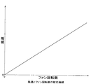
演算回路43には予め図7に示すような風速とファン回転数の較正曲線が記憶されており、風速検出回路42にて検出された風速は該演算回路43に送られ、風速から貫流ファン3の回転数を算出することができるようになっている。演算回路43は算出した回転数から運転状態を判断して、インバータ44より最適な電源電圧及び電源周波数の駆動電力をモータ12のモータステータ12aの巻線に供給する。
【0054】
これによりレーザ容器1内のレーザガス圧が変化し貫流ファン3の負荷が変わっても貫流ファン3の回転数が一定回転となり、主放電電極2、2の間で安定した高繰返し放電が行なえる。なお、風速とファン回転数の較正曲線は、貫流ファン3の特性上レーザガス圧が変化しても不変である。
【0055】
【発明の効果】
以上、説明したように各請求項に記載の発明によれば、下記のような優れた効果が得られる。
【0056】
回転数検出手段で検出したファン回転数からモータへの電源電圧及び電源周波数の一方若しくは両方を制御し、該ファンの回転数を一定に制御するから、レーザガスの封入圧力に無関係にファンの回転数を一定にでき、安定した高繰返し発振運転が行なえるエキシマレーザ装置を提供できる。また、モータを常に効率よく動作させるため、ファンの消費電力を低減できる。
【0057】
また、コイルを取り付けた磁性体をキャンを挟んでレーザ容器外に配置したので、レーザガスに対して耐腐食性の乏しいコイル等がレーザガスに曝されることなく、且つレーザガスを劣化させることもない。
【0058】
また、ファンの回転数を正確に検出することができるから、ファンの回転数をより精度よく一定に制御できる。
【0059】
また、円板はパーマロイ、PCパーマロイで作られているから、腐食性の強いレーザガスに曝されても腐食することがない。
【0060】
円板に設けるスリットを直径方向に対向する一対或いは偶数個とするので、円板の回転の際のバランスがよい。
【0061】
また、コイルを取り付ける磁性体の一部若しくは全部を永久磁石とするので、磁性体と円板で形成される磁気回路の磁束密度が増し、コイルに発生する誘導起電力が大きくなり、ファンの回転数の検出性能が高まる。また、磁束を形成するコイルへのバイアス電流も低減、若しくは不要にできるので、回路の簡略化、省電力化が達成できる。
【図面の簡単な説明】
【図1】 本発明に係るエキシマレーザ装置の構成例を示す図である。
【図2】 図1のA部分の詳細を示す図である。
【図3】 パーマロイのフッ素に対する耐腐食性試験の結果を示す図である。
【図4】 本発明に係るエキシマレーザ装置の貫流ファンの回転数検出手段の動作を説明するための図である。
【図5】 本発明に係るエキシマレーザ装置の貫流ファンの回転数検出手段のコイルに発生する起電力模式図である。
【図6】 本発明に係るエキシマレーザ装置の構成例を示す図である。
【図7】 風速とファン回転数の較正曲線を示す図である。
【図8】 従来のエキシマレーザ装置の概略構成を示す図である。
【符号の説明】
1 レーザ容器
2 主放電電極
3 貫流ファン
4 回転軸
5 窓
6 軸受ハウジング
7 モータハウジング
8 ラジアル磁気軸受
9 ラジアル磁気軸受
10 ラジアル磁気軸受
11 アキシャル磁気軸受
12 モータ
13 スリット付円板
14 コイル
15 U形磁性体
16〜20 キャン
21 側板
22 水冷ジャケット
30 制御回路
31 回転数検出回路
32 演算回路
33 インバータ
40 風速測定手段
41 制御回路
42 風速検出回路
43 演算回路
44 インバータ[0001]
BACKGROUND OF THE INVENTION
The present invention relates to an excimer laser device, and more particularly, to an excimer laser device including a control unit that detects the rotational speed of a fan that generates a laser gas flow and controls the rotational speed of the fan to be constant.
[0002]
[Prior art]
FIG. 8 is a diagram showing a schematic configuration of a conventional excimer laser device. In the conventional excimer laser device, as shown in the figure, a preionization electrode (not shown) for preionizing the laser gas and a discharge that enables oscillation of the laser light are obtained inside a
[0003]
[0004]
In the excimer laser device having the above structure, since the laser gas contains a highly reactive halogen gas such as fluorine, various chemical changes occur in the
[0005]
Further, in order to realize an excimer laser having an average output of laser light of several tens of watts or more, high repetition discharge of several kHz is indispensable in the
[0006]
Therefore, as a means for solving the above problem, in the excimer laser apparatus, the discharge voltage applied between the
[0007]
[Problems to be solved by the invention]
However, the excimer laser apparatus as described above has a problem that the load on the
[0008]
In order to solve the above problem, there is a method in which the rotational speed of the once-through
[0009]
The present invention has been made in view of the above points, and even if the pressure of the laser gas sealed in the laser container changes, the rotation speed of the fan can be kept constant, and the laser gas flow between the main discharge electrodes can be made constant. An object of the present invention is to provide an excimer laser device that can perform a high-repetition oscillation operation even when the sealing pressure of the laser gas changes and consumes less power.
[0010]
[Means for Solving the Problems]
In order to solve the above-mentioned problems, a first aspect of the present invention provides a laser container that encloses a laser gas , and a pair of main discharge electrodes that are disposed in the laser container and excite the laser gas at a high repetition frequency to generate a discharge. When detects a fan to create the flow of high-speed laser gas between the pair of main discharge electrodes, a bearing for rotatably supporting the rotation shaft of the fan, a motor for driving the fan, the rotational speed of the fan A rotation speed detecting means for controlling the voltage and / or frequency supplied to the motor on the basis of the rotation speed of the fan detected by the rotation speed detection means. in an excimer laser device having a control means for controlling the rotational speed detecting means comprises a magnetic material secured to the rotating shaft of the fan is disposed in the airtight space which communicates with the laser vessel A disc, characterized by comprising an outwardly circular plate and facing the meantime disposed interposed the can a magnetic material to the position of the laser container.
[0011]
According to a second aspect of the present invention, in the excimer laser device according to the first aspect, the disk has one or a plurality of slits.
[0012]
The invention according to
[0013]
According to a fourth aspect of the present invention, in the excimer laser device according to the first aspect, the coil is attached to the magnetic body, and the rotational speed of the fan is detected from the electromotive force induced in the coil by the rotation of the disk. Features.
[0014]
According to a fifth aspect of the present invention, in the excimer laser device according to the first aspect, the magnetic body is a U-shaped magnetic body with a coil attached thereto.
[0015]
The invention described in claim 6 is the excimer laser device according to claim 1, wherein the disc is made of permalloy.
[0016]
The invention described in claim 7 is the excimer laser device according to claim 1, wherein the disc is made of PC permalloy.
[0017]
According to an eighth aspect of the present invention, in the excimer laser device according to the first aspect, the circular plate has a pair of slits opposed in the diameter direction.
[0018]
According to a ninth aspect of the present invention, in the excimer laser device according to the first aspect, the circular plate has an even number of slits opposed in the diameter direction.
[0019]
According to a tenth aspect of the present invention, in the excimer laser device according to the first aspect, the motor is an induction motor.
[0020]
According to an eleventh aspect of the present invention, in the excimer laser device according to the first aspect, a part or the whole of the magnetic material is composed of a permanent magnet.
[0021]
As described above, the control unit controls one or both of the voltage and frequency to the motor from the fan rotation number detected by the rotation number detection unit, and controls the rotation number of the fan to be constant. Irrespective of this, it is possible to provide an excimer laser device that can keep the rotational speed of the fan constant and perform stable high-repetition oscillation operation. Further, since the motor is always operated efficiently, the power consumption of the fan can be reduced.
[0022]
The rotational speed detection means for detecting the rotational speed of the fan is made of a magnetic material fixed to the rotational shaft of the fan as described above, and is arranged on the outside of the laser container, and a disk disposed in an airtight space communicating with the laser container. with the structure comprising a circular plate opposing the meantime disposed interposed the can a magnetic material in a position, it is possible to accurately detect the rotational speed of the fan. Further, since the magnetic body with the coil attached is disposed outside the laser container with the can interposed therebetween, the coil having poor corrosion resistance against the laser gas is not exposed to the laser gas, and the laser gas is not deteriorated.
[0023]
By configuring a part or the whole of the magnetic body to which the coil is attached as a permanent magnet, the magnetic flux density of the magnetic circuit formed by the magnetic body and the disk increases, so that the induced electromotive force generated in the coil increases, The detection performance of the rotational speed is increased. In addition, since the bias current to the coil forming the magnetic flux can be reduced or eliminated, circuit simplification and power saving can be achieved.
[0024]
DETAILED DESCRIPTION OF THE INVENTION
Embodiments of the present invention will be described below with reference to the drawings. FIG. 1 is a diagram showing a configuration example of an excimer laser device according to the present invention, and FIG. 2 is a diagram showing details of a portion A of FIG. The configuration of the excimer laser device according to the present invention will be described with reference to FIGS.
[0025]
Inside the laser container 1 in which the laser gas is sealed, there are a preionization electrode (not shown) for preionizing the laser gas and a pair of
[0026]
The oscillation of the laser beam is obtained by performing laser excitation discharge by applying a high voltage between the pair of
[0027]
The
[0028]
An axial
[0029]
FIG. 3 is a diagram showing the results of a permalloy corrosion resistance test for fluorine. As shown in the figure, permalloy has better corrosion resistance as the Ni content increases, and PC permalloy (JIS C2531) with an Ni content of 80% shows almost the same corrosion resistance as austenitic stainless steel SUS316L. Therefore, it is better to use PC permalloy.
[0030]
On the other hand, in the bearing housing 6, a U-shaped
[0031]
The right electromagnet 11b and the
[0032]
The displacement sensor 8a and the electromagnet 8b of the radial
[0033]
On the other hand, the
[0034]
Here, as a magnetic material constituting the
[0035]
Further, in the
[0036]
In the motor housing 7, a displacement sensor 9a of the radial
[0037]
A
[0038]
On the other hand, on the
[0039]
Further, since the motor rotor 12b of the
[0040]
The
[0041]
Next, the operation for detecting the rotation of the
[0042]
When the relative positions of the
[0043]
ф 1 = NI / {(l 1 / μ 1 S) + (l 2 / μ 2 S) + (2x / μ 0 S)} (1)
N: number of turns of
[0044]
Next, the magnetic flux ф 2 when the relative position of the
[0045]
ф 2 = NI / {(l 2 / μ 1 S) + (l ′ / μ 0 S)} (2)
l ′: the space's virtual self-magnetic path length {see FIG. 4 (f)}
[0046]
The
e = NΔф / t (3)
Inductive electromotive force is generated.
[0047]
That is, when the disk with
[0048]
From the above operating principle, the detection sensitivity is better when the change in magnetic flux when passing through the
[0049]
As described above, the rotational speed of the
[0050]
In the above-described embodiment, the magnetic body has been described as the U-shaped
[0051]
FIG. 6 is a diagram showing another configuration example of the excimer laser device according to the present invention. In FIG. 6, the same reference numerals as those in FIG. 1 denote the same or corresponding parts, and the description thereof is omitted.
[0052]
A wind speed measuring means 40 is installed in the laser container 1, and the wind speed measuring means 40 is connected to a wind
[0053]
The
[0054]
Thereby, even if the laser gas pressure in the laser container 1 changes and the load of the
[0055]
【The invention's effect】
As described above, according to the invention described in each claim, the following excellent effects can be obtained.
[0056]
Since one or both of the power supply voltage and the power supply frequency to the motor are controlled from the fan rotational speed detected by the rotational speed detection means, and the rotational speed of the fan is controlled to be constant, the rotational speed of the fan is independent of the sealing pressure of the laser gas. It is possible to provide an excimer laser device that can maintain a constant frequency and can perform stable high-repetition oscillation operation. Further, since the motor is always operated efficiently, the power consumption of the fan can be reduced.
[0057]
Further, since the magnetic body with the coil attached is disposed outside the laser container with the can interposed therebetween, the coil having poor corrosion resistance against the laser gas is not exposed to the laser gas, and the laser gas is not deteriorated.
[0058]
Further, since the rotational speed of the fan can be accurately detected, the rotational speed of the fan can be controlled more accurately and constantly.
[0059]
Further, since the disc is made of permalloy or PC permalloy, it does not corrode even when exposed to highly corrosive laser gas.
[0060]
Since the slits provided in the disk are a pair or an even number of slits facing each other in the diametrical direction, the balance in rotating the disk is good.
[0061]
In addition, since a part or all of the magnetic material to which the coil is attached is a permanent magnet, the magnetic flux density of the magnetic circuit formed by the magnetic material and the disk is increased, the induced electromotive force generated in the coil is increased, and the rotation of the fan Number detection performance increases. In addition, since the bias current to the coil forming the magnetic flux can be reduced or eliminated, circuit simplification and power saving can be achieved.
[Brief description of the drawings]
FIG. 1 is a diagram showing a configuration example of an excimer laser device according to the present invention.
FIG. 2 is a diagram showing details of a portion A in FIG. 1;
FIG. 3 is a diagram showing the results of a permalloy corrosion resistance test for fluorine.
FIG. 4 is a diagram for explaining the operation of the rotational speed detection means of the cross-flow fan of the excimer laser device according to the present invention.
FIG. 5 is a schematic view of an electromotive force generated in a coil of a rotational speed detecting means of a cross-flow fan of an excimer laser device according to the present invention.
FIG. 6 is a diagram showing a configuration example of an excimer laser device according to the present invention.
FIG. 7 is a diagram showing a calibration curve for wind speed and fan speed.
FIG. 8 is a diagram showing a schematic configuration of a conventional excimer laser device.
[Explanation of symbols]
DESCRIPTION OF SYMBOLS 1
Claims (11)
前記回転数検出手段は、前記ファンの回転軸に固着された磁性材料からなり、前記レーザ容器に連通する気密空間に配置された円板と、該レーザ容器の外側で該円板と対向する位置にその間にキャンを介在して配置された磁性体とを具備することを特徴とするエキシマレーザ装置。A laser container for enclosing the laser gas is disposed in the laser chamber, a pair of main discharge electrodes for generating excited to discharge the laser gas at a high repetition frequency, the flow of high-speed laser gas between the pair of main discharge electrodes , A bearing that rotatably supports the rotation shaft of the fan, a motor that drives the fan, a rotation speed detection means for detecting the rotation speed of the fan, and the rotation speed detection means. In addition, in the excimer laser device provided with the control means for controlling the rotational speed of the fan to be constant by controlling one or both of the voltage and frequency supplied to the motor based on the rotational speed of the fan .
The rotational speed detection means is made of a magnetic material fixed to the rotation shaft of the fan, and is disposed in an airtight space communicating with the laser container, and a position facing the disk outside the laser container. An excimer laser device comprising: a magnetic material disposed between the magnetic material and a can therebetween.
前記円板は1個又は複数個のスリットを有することを特徴とするエキシマレーザ装置。The excimer laser device according to claim 1,
The excimer laser device, wherein the disc has one or a plurality of slits .
前記磁性体の幅は前記スリットの幅より小さいことを特徴とするエキシマレーザ装置。The excimer laser device according to claim 2,
An excimer laser device characterized in that a width of the magnetic body is smaller than a width of the slit .
前記磁性体にコイルを取り付け、前記円板の回転により前記コイルに誘導される起電力から前記ファンの回転数を検出することを特徴とするエキシマレーザ装置。 The excimer laser device according to claim 1,
An excimer laser device, wherein a coil is attached to the magnetic body, and the rotational speed of the fan is detected from an electromotive force induced in the coil by the rotation of the disk.
前記磁性体はコイルを取付けたU型磁性体であることを特徴とするエキシマレーザ装置。An excimer laser device, wherein the magnetic body is a U-shaped magnetic body with a coil attached thereto.
前記円板はパーマロイで作られていることを特徴とするエキシマレーザ装置。An excimer laser device, wherein the disc is made of permalloy.
前記円板はPCパーマロイで作られていることを特徴とするエキシマレーザ装置。An excimer laser device, wherein the disc is made of PC permalloy.
前記円板は直径方向に対向する一対のスリットを有することを特徴とするエキシマレーザ装置。The excimer laser device, wherein the disk has a pair of slits facing each other in the diameter direction.
前記円板は直径方向に対向する偶数個のスリットを有することを特徴とするエキシマレーザ装置。The excimer laser device, wherein the disk has an even number of slits opposed in the diameter direction.
前記モータは誘導モータであることを特徴とするエキシマレーザ装置。An excimer laser device, wherein the motor is an induction motor.
前記磁性体の一部若しくは全体が永久磁石で構成されていることを特徴とするエキシマレーザ装置。An excimer laser device characterized in that a part or the whole of the magnetic material is composed of a permanent magnet.
Priority Applications (6)
| Application Number | Priority Date | Filing Date | Title |
|---|---|---|---|
| JP11397299A JP3766230B2 (en) | 1999-04-21 | 1999-04-21 | Excimer laser equipment |
| TW089107213A TW444423B (en) | 1999-04-21 | 2000-04-18 | Excimer laser device |
| US09/553,466 US6366039B1 (en) | 1999-04-21 | 2000-04-19 | Excimer laser device |
| KR1020000021029A KR100654409B1 (en) | 1999-04-21 | 2000-04-20 | Excimer laser device |
| DE60040256T DE60040256D1 (en) | 1999-04-21 | 2000-04-20 | Excimer laser device |
| EP00108648A EP1047162B1 (en) | 1999-04-21 | 2000-04-20 | Excimer laser device |
Applications Claiming Priority (1)
| Application Number | Priority Date | Filing Date | Title |
|---|---|---|---|
| JP11397299A JP3766230B2 (en) | 1999-04-21 | 1999-04-21 | Excimer laser equipment |
Publications (3)
| Publication Number | Publication Date |
|---|---|
| JP2000307175A JP2000307175A (en) | 2000-11-02 |
| JP2000307175A5 JP2000307175A5 (en) | 2004-11-18 |
| JP3766230B2 true JP3766230B2 (en) | 2006-04-12 |
Family
ID=14625839
Family Applications (1)
| Application Number | Title | Priority Date | Filing Date |
|---|---|---|---|
| JP11397299A Expired - Lifetime JP3766230B2 (en) | 1999-04-21 | 1999-04-21 | Excimer laser equipment |
Country Status (6)
| Country | Link |
|---|---|
| US (1) | US6366039B1 (en) |
| EP (1) | EP1047162B1 (en) |
| JP (1) | JP3766230B2 (en) |
| KR (1) | KR100654409B1 (en) |
| DE (1) | DE60040256D1 (en) |
| TW (1) | TW444423B (en) |
Cited By (1)
| Publication number | Priority date | Publication date | Assignee | Title |
|---|---|---|---|---|
| US10250008B2 (en) | 2015-03-12 | 2019-04-02 | Gigaphoton Inc. | Discharge excitation gas laser apparatus |
Families Citing this family (12)
| Publication number | Priority date | Publication date | Assignee | Title |
|---|---|---|---|---|
| JP2001111138A (en) * | 1999-10-04 | 2001-04-20 | Ebara Corp | Excimer laser apparatus |
| EP1119082A3 (en) * | 2000-01-18 | 2004-05-26 | Ushiodenki Kabushiki Kaisha | Cross-flow fan for discharge excited gas laser |
| JP2001234929A (en) * | 2000-02-21 | 2001-08-31 | Ebara Corp | Magnetic bearing and circulating fan device |
| JP2001352114A (en) * | 2000-06-08 | 2001-12-21 | Ebara Corp | Magnetic bearing device for excimer laser equipment |
| EP1188932A3 (en) * | 2000-09-19 | 2003-05-02 | Ntn Corporation | Bearing structure for laser fan |
| JP2002345210A (en) * | 2001-05-11 | 2002-11-29 | Ebara Corp | Motor and excimer laser apparatus |
| US7664154B2 (en) | 2004-04-21 | 2010-02-16 | Mitsubishi Electric Corporation | Gas laser oscillator and gas laser beam machine |
| JP4146867B2 (en) * | 2006-06-22 | 2008-09-10 | ファナック株式会社 | Gas laser oscillator |
| JP6063199B2 (en) * | 2012-10-15 | 2017-01-18 | ギガフォトン株式会社 | Discharge excitation type gas laser equipment |
| WO2017094099A1 (en) * | 2015-12-01 | 2017-06-08 | ギガフォトン株式会社 | Excimer laser device |
| CN114183468B (en) * | 2021-12-08 | 2022-11-15 | 珠海格力电器股份有限公司 | Compressor and air conditioner |
| CN114183932A (en) * | 2021-12-17 | 2022-03-15 | 珠海格力电器股份有限公司 | Gas water heater and fan rotating speed detection method and device |
Family Cites Families (3)
| Publication number | Priority date | Publication date | Assignee | Title |
|---|---|---|---|---|
| US5377215A (en) * | 1992-11-13 | 1994-12-27 | Cymer Laser Technologies | Excimer laser |
| CA2190697C (en) | 1996-01-31 | 2000-07-25 | Donald Glenn Larson | Blower motor with adjustable timing |
| US6026103A (en) * | 1999-04-13 | 2000-02-15 | Cymer, Inc. | Gas discharge laser with roller bearings and stable magnetic axial positioning |
-
1999
- 1999-04-21 JP JP11397299A patent/JP3766230B2/en not_active Expired - Lifetime
-
2000
- 2000-04-18 TW TW089107213A patent/TW444423B/en not_active IP Right Cessation
- 2000-04-19 US US09/553,466 patent/US6366039B1/en not_active Expired - Lifetime
- 2000-04-20 KR KR1020000021029A patent/KR100654409B1/en active IP Right Grant
- 2000-04-20 EP EP00108648A patent/EP1047162B1/en not_active Expired - Lifetime
- 2000-04-20 DE DE60040256T patent/DE60040256D1/en not_active Expired - Lifetime
Cited By (1)
| Publication number | Priority date | Publication date | Assignee | Title |
|---|---|---|---|---|
| US10250008B2 (en) | 2015-03-12 | 2019-04-02 | Gigaphoton Inc. | Discharge excitation gas laser apparatus |
Also Published As
| Publication number | Publication date |
|---|---|
| KR100654409B1 (en) | 2006-12-05 |
| EP1047162A3 (en) | 2003-10-01 |
| JP2000307175A (en) | 2000-11-02 |
| TW444423B (en) | 2001-07-01 |
| EP1047162A2 (en) | 2000-10-25 |
| KR20000077056A (en) | 2000-12-26 |
| EP1047162B1 (en) | 2008-09-17 |
| DE60040256D1 (en) | 2008-10-30 |
| US6366039B1 (en) | 2002-04-02 |
Similar Documents
| Publication | Publication Date | Title |
|---|---|---|
| JP3766230B2 (en) | Excimer laser equipment | |
| TW445682B (en) | Gas discharge laser with magnetic bearings and magnetic reluctance centering for fan drive assembly | |
| JP2000307175A5 (en) | ||
| US6519273B2 (en) | Magnetic bearing and circulation fan apparatus | |
| JP4189037B2 (en) | Magnetic shaft support electric drive | |
| JPH11303793A (en) | Circulation fan device and circulation fan driving motor | |
| TW463429B (en) | Discharge-pumped excimer laser device | |
| US6809448B2 (en) | Excimer laser apparatus | |
| JP4049531B2 (en) | Magnetic bearing motor and excimer laser device | |
| JP2000183436A (en) | Excimer laser | |
| JP3927327B2 (en) | Gas laser device containing halogen gas | |
| TW522619B (en) | Excimer laser apparatus | |
| JP2003283010A (en) | Gas laser apparatus | |
| TW478222B (en) | Excimer laser | |
| JP4555435B2 (en) | Liquid pump device | |
| JP2003134733A (en) | Electromagnetic bearing motor and excimer laser apparatus using the same | |
| JP2982881B2 (en) | Gap detection device | |
| JP4322170B2 (en) | Magnetic bearing device and excimer laser device provided with magnetic bearing | |
| JP2009065746A (en) | Canned motor drive system | |
| JP3600047B2 (en) | Secondary current detection device for induction motor | |
| JPH04178145A (en) | Magnetic torque transmitting device | |
| JP2000340864A (en) | Excimer laser | |
| JP2000183427A (en) | Flow through fan for excimer laser | |
| JP2000261069A (en) | Excimer laser | |
| JP2001332795A (en) | Excimer laser |
Legal Events
| Date | Code | Title | Description |
|---|---|---|---|
| A977 | Report on retrieval |
Free format text: JAPANESE INTERMEDIATE CODE: A971007 Effective date: 20060116 |
|
| TRDD | Decision of grant or rejection written | ||
| A01 | Written decision to grant a patent or to grant a registration (utility model) |
Free format text: JAPANESE INTERMEDIATE CODE: A01 Effective date: 20060124 |
|
| A61 | First payment of annual fees (during grant procedure) |
Free format text: JAPANESE INTERMEDIATE CODE: A61 Effective date: 20060126 |
|
| R150 | Certificate of patent or registration of utility model |
Free format text: JAPANESE INTERMEDIATE CODE: R150 |
|
| S111 | Request for change of ownership or part of ownership |
Free format text: JAPANESE INTERMEDIATE CODE: R313117 |
|
| R350 | Written notification of registration of transfer |
Free format text: JAPANESE INTERMEDIATE CODE: R350 |
|
| FPAY | Renewal fee payment (event date is renewal date of database) |
Free format text: PAYMENT UNTIL: 20100203 Year of fee payment: 4 |
|
| FPAY | Renewal fee payment (event date is renewal date of database) |
Free format text: PAYMENT UNTIL: 20110203 Year of fee payment: 5 |
|
| FPAY | Renewal fee payment (event date is renewal date of database) |
Free format text: PAYMENT UNTIL: 20120203 Year of fee payment: 6 |
|
| FPAY | Renewal fee payment (event date is renewal date of database) |
Free format text: PAYMENT UNTIL: 20120203 Year of fee payment: 6 |
|
| FPAY | Renewal fee payment (event date is renewal date of database) |
Free format text: PAYMENT UNTIL: 20130203 Year of fee payment: 7 |
|
| FPAY | Renewal fee payment (event date is renewal date of database) |
Free format text: PAYMENT UNTIL: 20140203 Year of fee payment: 8 |
|
| R250 | Receipt of annual fees |
Free format text: JAPANESE INTERMEDIATE CODE: R250 |
|
| R250 | Receipt of annual fees |
Free format text: JAPANESE INTERMEDIATE CODE: R250 |
|
| R250 | Receipt of annual fees |
Free format text: JAPANESE INTERMEDIATE CODE: R250 |
|
| R250 | Receipt of annual fees |
Free format text: JAPANESE INTERMEDIATE CODE: R250 |
|
| R250 | Receipt of annual fees |
Free format text: JAPANESE INTERMEDIATE CODE: R250 |
|
| R250 | Receipt of annual fees |
Free format text: JAPANESE INTERMEDIATE CODE: R250 |
|
| EXPY | Cancellation because of completion of term |