JP3765295B2 - Electronic keyboard instrument - Google Patents
Electronic keyboard instrument Download PDFInfo
- Publication number
- JP3765295B2 JP3765295B2 JP2002255421A JP2002255421A JP3765295B2 JP 3765295 B2 JP3765295 B2 JP 3765295B2 JP 2002255421 A JP2002255421 A JP 2002255421A JP 2002255421 A JP2002255421 A JP 2002255421A JP 3765295 B2 JP3765295 B2 JP 3765295B2
- Authority
- JP
- Japan
- Prior art keywords
- housing
- plate portion
- portions
- slide
- casing
- Prior art date
- Legal status (The legal status is an assumption and is not a legal conclusion. Google has not performed a legal analysis and makes no representation as to the accuracy of the status listed.)
- Expired - Fee Related
Links
Images


Description
【0001】
【発明の属する技術分野】
本発明は、電子鍵盤楽器の筐体構造に関する。
【0002】
【従来の技術】
全体としてフラットな盤状の筐体形状を有する電子鍵盤楽器において、その筐体構造は、鍵盤部が載置される底板部と、鍵盤部の前に位置する口棒部と、鍵盤部の左右側に位置する左右の側板部と、後方上面を構成する屋根板部と、背面板部とで構成され、一般にこれらの各板部がネジ等を介して相互に結合されることで、ケース状の筐体が形成される。しかし、このような筐体構成では筐体内部の保守点検を行う際の筐体の分解及び再組立作業が面倒であった。
これに対して、実開昭62−103382号公報には、電子鍵盤楽器の筐体を上面部及び背面部を一体化した後方カバーと本体部とで構成し、本体部に備わる底板部に対して後方カバーを蝶番によって結合し、該後方カバーを開閉可能にしたものが示されている。しかし、この場合は、筐体を組み立てる際に、後方カバーを本体部に固定するための最後のネジ締めが必ず筐体上面側においてなされるので、ネジ頭が上面に露出してしまい、外観上好ましくなかった。また、後方カバーは筐体本体部に対して着脱自在ではないため、組立が面倒であり、筐体内部の回路基板等の保守点検もやりにくい面があった。
【0003】
また、上述のタイプの電子鍵盤楽器にあっては、保守点検のしやすさ等を考慮して、メイン回路基板は底板部に配置されていた。しかし、メイン回路基板を鍵盤部の背後において底板部上に設ける場合は、底板部の前後方向のサイズを大きくせざるを得ず、楽器の前後方向のサイズが大きくなってしまう。また、メイン回路基板を鍵盤部の下側において底板部上に設ける場合は、楽器のたて方向の厚みが増してしまう。
【0004】
【発明の解決しようとする課題】
本発明は上述の点に鑑みてなされたもので、筐体を見栄えよくかつ簡便に組み立てることができ、また筐体内部の保守点検もしやすい筐体構造を有する電子鍵盤楽器を提供しようとするものである。
【0005】
【課題を解決する手段】
本発明は、鍵盤部と、該鍵盤部を配置した筐体とを具備する電子鍵盤楽器において、前記筐体は、底板部と側板部と背面板部と屋根板部とを有し、前記底板部に前記鍵盤部が載置され、少なくとも前記底板部を含む第1の筐体部分に対して少なくとも前記屋根板部と前記背面板部とを含む第2の筐体部分が着脱可能であり、前記側板部は前記第1又は第2の筐体部分のいずれかに帰属し、前記第2の筐体部分に結合保持手段を有すると共に、前記背面板部において内側に折れ曲がった下縁部を有し、該結合保持手段の下端部を前記底板部の上面に位置させて前記第2の筐体部分を前記第1の筐体部分に対してスライド装着することで前記第1の筐体部分の前記底板部を前記第2の筐体部分の前記結合保持手段と前記背面板部との間に挟み込み、この挟み込まれた状態で固着することにより該第2の筐体部分を該第1の筐体部分に対して着脱式に取り付けてなる前記筐体を構成するようにしてなり、かつ、前記背面板部の内側に当該電子鍵盤楽器の回路部品が取り付けられていることを特徴とする。これによれば、第2の筐体部分側の結合保持手段の下端部を、第1の筐体部分側の底板部の上面に位置させて、第2の筐体部分を第1の筐体部分に対してスライド装着する構成であるため、第2の筐体部分に重量物があってもこれを確実に保持してスライド装着及び固着を行うことができ、また、第1の筐体部分側の底板部を第2の筐体部分側の結合保持手段と背面板部との間に挟み込み、この挟み込まれた状態で固着するので、第1の筐体部分と第2の筐体部分とが分離しにくく、その一方で、脱着も容易であるため内部の保守点検もし易い、優れた筐体構造を提供することができる。更に、背面板部の内側に当該電子鍵盤楽器の回路部品を取り付けるようにしているので、第2の筐体部分を取り外し方向に比較的少量スライドするだけで、背面板部の内側の回路部品の取り付け状態を確認することができ、保守点検がし易いという利点がある。
【0007】
【発明の実施の形態】
以下、添付図面を参照して本発明の一実施例について説明する。
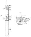
図1(a)は本発明に係る電子鍵盤楽器の一例を示す平面図であり、(b)にその背面図、(c)に底面図をそれぞれ示す。本実施例に係る電子鍵盤楽器の筐体1は、大別して筐体本体部2と筐体後部3とで構成され、図2に略示するように筐体本体部2に対して筐体後部3が着脱式に取り付けられる。筐体本体部2は、鍵盤部9が載置される底板部5と、鍵盤部9の前で底板部5から立ち上がる口棒部8と、鍵盤部9の左右側で底板部5から立ち上がる左右の側板部6a、6bとを含み、これら底板部5、側板部6a,6b及び口棒部8はネジ等適宜の接合手段を介して相互に接合固定されている。筐体後部3は、筐体1の後方上面を構成する屋根板部4と、屋根板部4の後縁から立ち下がる背面板部7とを含み、屋根板部4と背面板部7はネジ等適宜の接合手段を介して相互に接合固定されている。背面板部7には、図1(b)に示すように、メイントーンホール10a,10bが設けられており、これらは左右両スピーカ(図示せず)からの音響出力の放音口である。屋根板部4の所定個所には、図1(a)に示すように、スピーカ裏面からの音響振動を放音する開口部であるサブトーンホール11a,11bと各種操作スイッチ及び表示器等を含む操作パネル12とが設けられている。
【0008】
筐体本体部2に対する筐体後部3の取付は、筐体後部3を筐体本体部2に対してスライド固着するスライド固着手段を介して行われる。最初に説明する実施例においては、スライド固着手段を構成する機構は、筐体後部3においては屋根板部4の下面に設けられ、筐体本体部2においては左右側板部6a,6bの上端部に設けられており、これにより、該スライド固着手段は、筐体後部3を筐体本体部2の左右側板部6a,6bに対してスライド固着するように構成されている。
【0009】
まず、筐体後部3の具体例について図3(a)〜(c)を参照して説明する。(a)は筐体1内側から背面板部7の裏面を見た筐体後部3の立面図であり、(b)は図3(a)の矢印aから屋根板部4の下面を矢視した図であり、(c)は筐体後部3の側面を図3(a)の矢印bから矢視した右側面図である。筐体後部3を構成する屋根板部4と背面板部7とは略々直角に結合されており、左右及び中央の3個所で結合保持板21a〜21cを介して両者の結合が補強されている。右側の結合保持板21aについて図3(c)により説明すると、その後端部で背面板部7と結合し、上端部で屋根板部4と結合しており、下端部53aは保持板21aの垂直部から連設された折れ曲がり部となっていて、後述するように底板部5にネジ等を介して結合できるようになっている。他の結合保持板21b,21cも同様に構成されている。背面板部7の左右端方寄りの所定個所には、図3(a)に示すように、それぞれスピーカ20a,2bが具えられている。中央の結合保持板21cは左右スピーカ20a,20b間の音響分離の役目も果たしている。また、背面板部7の下縁部51は内側に向けて略水平方向に折れ曲がっており、後述するように、底板部5の一辺縁に接してネジ等を介して接合される。
【0010】
図3(b)に示すように、屋根板部4の裏面の左右端部寄りの所定個所には、筐体後部3を左右側板部6a,6bに対してスライド固着するためのスライド固着手段の一構成要素として、突起部31a〜31dがそれぞれ設けられている。図3(c)により屋根板部4裏面の右端部に設けられたスライド固着用突起部31a、31bについて説明すると、これらは前方寄り及び後方寄りの所定個所にそれぞれ設けられている。突起部31a、31bのそれぞれの先端部にはネジ頭33a、33bが形成されており、このネジ頭33a、33bから所定間隔開けたところにつば部34a、34bを有しており、このネジ頭33a、33bとつば部34a、34bの間にスライド用の隙間部32a、32bが形成されている。屋根板部4裏面の左端部に具備されているスライド固着用突起部31c,31dも同様な構成である。
【0011】
次に、筐体本体部2の左右側板部6a,6bの側に設けられるスライド固着手段の構成要素の一例について、図4及び図5により説明する。図4は筐体本体部2の上面図であり、図5(a)はその右側板部6aの上面を拡大して示す図である。筐体本体部2の左右両側板部6a,6bの後方上面において、前記筐体後部3の前記スライド固着用突起部31a〜31dに対応する配置でスライド部35a〜35dがそれぞれ設けられている。図5(a)に示すとおり、各スライド部35a、35bは、大孔部36a、36bと、この大孔部36a、36bに連なり筐体前方に延びた長孔部37a、37bを具備しており、その周囲には凹部38a,38bが形成されている。大孔部36a、36bは、対応するスライド固着用突起部31a,31bのネジ頭33a,33bの挿通を許すサイズの径を有し、長孔部37a、37bの横幅は、ネジ頭33a,33b及びつば部34a,34bの直径より小さい。凹部38a,38bは、筐体後部3と筐体本体部2が結合される際に、対応するスライド固着用突起部31a,31bのつば部34a、34bが嵌合する凹部であり、つば部34a、34bに適合する横幅と深さを有する。この凹部38a,38bの裏面の所定範囲において後述するようにテーパ面(図5(b)の39a)が形成されている。他のスライド部35c、35dも同様の構造を有する。
【0012】
筐体本体部2に対して筐体後部3を取り付けるには、図2に示すように、筐体本部2の背後から筐体後部3を設置し、屋根板部4下面のスライド固着用突起部31a〜31dのネジ頭33a,33b,…を、左右側板部6a,6bのスライド部35a〜35dの対応する大孔部36a,36b,…に落とし込み、その後筐体後部3全体を前方(矢印X方向)にスライドさせる。図5(b)は、図5(a)のG−G線断面図であり、スライド部35aに、これに対応する突起部31aを落とし込んだ状態を示す。この状態では、各突起部31a〜31dのつば部34a,34b,…はスライド部35a〜35dにおける対応する凹部38a,38b,…に位置し、各突起部31a〜31dの隙間部32a,32b,…はスライド部35a〜35dにおける対応する大孔部36a,36b,…の高さに位置し、各突起部31a〜31dのネジ頭33a,33b,…は対応する大孔部36a,36b,…よりも下に突出する。この状態から筐体後部3(図5(b)における屋根板部4)を前方つまり矢印X方向にスライドさせると、各突起部31a〜31dの隙間部32a,32b,…がスライド部35a〜35dの対応する長孔部37a,37b,…に案内されて前方に移動することができ、これによって筐体後部3が前方にスライドし、筐体本体部2に装着される。
【0013】
各スライド部35a〜35dにおける凹部38a,38b,…の裏面の所定範囲にはテーパ面39a,…がそれぞれ形成されている。テーパ面39a,…の傾斜は楽器前方に向かって下向きになされており、テーパ面39a,…の下方傾斜に従ってスライド部35a〜35dが次第に肉厚になってゆく。テーパ面39a,…の個所において、各スライド部35a〜35dの板厚は対応する突起部31a〜31dの隙間部32a,32b,…の幅よりも徐々に厚くなる。このため、筐体後部3のスライド完了位置(つまり筐体後部3の取り付け位置)において、隙間部32a,32b,…の個所で、すなわちネジ頭33a,33b,…とつば部34a,34b,…の間で、それぞれに対応するスライド部35a〜35dをきつく狭持する。すなわち、テーパー面39a,…を登りきったネジ頭33a,33b,…がスライド部35a〜35dの厚みにより下方へ押し下げられるので、屋根板部4は左右側板部6a,6bに強く押し付けられ固定される。このようにして、筐体後部3は、前方にスライドされて側板部6a,6bに固着され、筐体本体部2に対して取り付けられる。
【0014】
図5(b)に示すように、スライド部35a〜35d裏面の後方端部には、それぞれアジャスタ突起部40a,…が設けられている。アジャスタ突起部40a,…は、各スライド部35a〜35dの大孔部36a,36b,…の直後に設けられており、筐体本体部2から取り外すために筐体後部3を後方にスライドした際、スライド固着用突起部31a〜31dのネジ頭33a,33b,…は、それぞれ対応するアジャスタ突起部40a,…でスライドを停止される。アジャスタ突起部40a,…により、スライド固着用突起部31a〜31dのネジ頭33a,33b,…を対応する大孔部36a,36b,…の下方に位置させることができる。よって、筐体後部3を筐体本体部2から取り外す作業を円滑に行える。
【0015】
筐体本体部2と筐体後部3は、上述のスライド固着手段による結合に加えて、次に述べるように、底板部5と筐体後部3の後方下端部においても、更に結合されており、その結合をより強固かつ確実なものとしている。
【0016】
背面板部7の下縁部51は、図3(c)に示すように、内側に向けて略水平方向に折れ曲がっており、この下縁部51にはネジ孔52a〜52fが設けられている。結合保持板21a〜21cの下端部53a〜53c(図3(a)参照)も折れ曲がり部となっていて、それぞれの下端部53a〜53cにはネジ孔54a〜54cが設けられている。背面板部7の下縁部51は底板部5の下面の高さの位置に位置し、結合保持板21a〜21cの下端部53a〜53cは底板部5の上面の高さ位置に位置しており、下縁部51と下端部53a〜53cの間に底板部5を挟み込む構造になっている。筐体後部3を筐体本体部2にスライド装着するときに、下縁部51と下端部53a〜53cの間に底板部5の後縁部が嵌入される。背面板部7の下縁部51は底板部5の下面側に接しており、各ネジ孔52a〜52fで底板部5に螺合される。また、結合保持板21a〜21cの下端部53a〜53cは底板部5の上面側に接しており、それぞれネジ孔54a〜54cで底板部5に螺合される。このネジ止めは、図1(c)に示されているように、全て底板部5の下面からなされる。背面板部7の下縁部51と結合保持板21a〜21cの下端部53a〜53cにおいて複数のネジ止めがなされ、かつ下縁部51と下端部53a〜53cのそれぞれのネジ止め位置が楽器の前後方向にずれているので、筐体本体部2に固定された筐体後部3は前後方向にガタツキにくい。
【0017】
筐体後部3を筐体本体部2から取り外すには、底板部5下面に施されたネジ止めを外し、筐体後部3を楽器後方(矢印Xと反対方向)にスライドさせる。これにより、筐体後部3の突起部31a〜31dとスライド部35a〜35dのテーパ面39a,…との係合・固着が解かれる。各突起部31a〜31dのネジ頭33a,33b,…は、スライド部35a〜35dに設けられたアジャスタ突起部40a…で停止され、それぞれの対応する大孔部36a,36b,…の下方の位置し、該大孔部36a,36b,…を通って上方に移動可能となる。よって、後方スライド停止位置で筐体後部3を持ち上げることで、筐体後部3を筐体本体部2から容易に取り外すことができる。
【0018】
図3に戻り、背面板部7には、音源等を含むメイン回路基板22a、22bが配設されており(図3(a)参照)、また屋根板部4裏面の操作パネル12下方に当たる個所に、パネル回路基板60が配置されている(図3(b)参照)。このように筐体後部3の側に回路基板を配置とすることで、前記回路基板は筐体後部3と共に筐体本体部2に対して着脱可能となる。よって、筐体1内の回路基板等の保守作業を行う場合は、筐体後部3を筐体本体部2から後方にスライドさせて取り外して、筐体後部3を作業しやすい状態に置いた上で、メイン回路基板22a、22b等の保守作業を行えばよいので、保守点検作業を行いやすい。また、底板部5にメイン回路基板22a、22b等を配置するスペースを設けなくてもよいため、底板部5の前後方向サイズを縮小でき、楽器サイズの小型化及び楽器の軽量化を図ることができる。
前記実施例では、左右側板部6a,6bを筐体本体部2に帰属してこれと一体的に設けたが、左右側板部6a,6bを筐体後部3に帰属してこれと一体的に設けるようにしてもよい。この場合にあっても筐体本体部2に対し筐体後部3を後方から着脱させる本発明の技術思想を反映させることができる。この場合は、当然屋根板部4と側板部6a,6bとは裏面(内側)からL型金具を介して一体構成とするが、側板部6a,6b前方と口棒部8左右両端部とにおいての嵌合は、単に突き合わせ構造のみとする。即ち、口棒部8両端面を左右側板部6a,6b前方内縁が前方スライドして重なり、軽く接する構成に仕上げればよい。口棒部8と底板部5との結合は、前述した結合保持板21a〜21cを小さくし簡素化した結合金具若しくはL型金具で結合するものとする。
【0019】
また、上述の例では、筐体後部3の後方下端部と筐体本体部2をネジ止めより固定する例を示したが、他の実施形態として、図6に示すように、ネジ止めを用いることなく、弾性変形嵌合手段(パッチン嵌合手段)で行うようにしてもよい。図6(a)は底板部5と背面板部7の一部を下面から見た概略斜視図であり、説明の便宜上、それぞれの左端部の一部分のみ図示して他を代表するものとする。図において、背面板部7の下縁部51には、切り溝51aを介して嵌合突起61が上向きに突設される。嵌合突起61には係合用の孔64が設けられている。嵌合突起61に対応する底板部5の下面の所定個所には、弾性変形型の嵌合係止部62が設けられている。図6(b)は嵌合係止部62だけを取り出して示す図で、見やすくするために(a)とは上下反転して示した。嵌合係止部62は、嵌合突起61の進入を許す凹部65と、先端に嵌合離脱用の操作部63bとそのすぐ内側で凹部65に臨むように設けられた係合突起63aとを有する弾性嵌合体63とで構成される。係合突起63aは片面テーパ状の先端を有し、凹部65内に進退自在に臨むよう作用する。
背面板部7と底板部5を結合する際、嵌合突起61を凹部65に挿入させると、嵌合突起61によって係合突起63aの片面テーパ部が押され、係合突起63aが凹部65から後退し、嵌合突起61の孔64に対応する位置で係合突起63aに対する係合突起61による押圧が解除され、弾性嵌合体63による反発力により係合突起63aが凹部65内に戻り、係合突起63aが嵌合突起61の孔64に嵌合する。係合突起63aが嵌合突起61の孔64に嵌合した状態を抽出して断面図にて示すと図6(c)のようである。こうして背面板部7と底板部5とが固定される。上記突起61が凹部65に嵌入する途中において、上記切り溝51aを設けたことで基部51bが弾性的になり背面板部7が底板部5に対しフレキシビリティを発生させ、スムーズな嵌合を可能にしている。
弾性嵌合体63において、係合突起64に略々直角に嵌合離脱用の操作部63bが形成されている。背面板部7と底板部5の取り外しを行う際は、前記操作部63bを引いて、係合突起63aを凹部65から後退させ、嵌合突起61の孔64に対する係合突起63aの嵌合を解き、嵌合突起61を凹部65から外す。
このような2つの弾性変形嵌合手段(弾性嵌合体63と基部51b)を用いると、筐体本体部2と筐体後部3の結合にネジ止めが一切不要となるので、筐体本体部2と筐体後部3の分解及び取り付け作業が容易になる。
【0020】
なお、スライド固着手段としては、上述のタイプに限らず、筐体本体部2に対して、筐体後部3をスライド移動した後、固着するものであればいかなる機構によるものでもよい。また、本実施例においては、屋根板部4の裏面と、それに対応する側板部6a,6bの上面とを係合させ、前後方向にスライドする例を示したが、これに限らず、例えば、背面板部7の裏面75と側板部6a,6bの後面を係合させ、上下方向にスライドするような構成等であってもよい。
また、上述の実施例においては、筐体後部3を構成する背面板部7と屋根板部4は略々直角をなして結合されていたが、これに限らず、例えば60度、120度、…等適宜角度を持って結合されていればよい。
筐体後部3にメイン回路部等を設ける構成のみを実施する場合は、上述のスライド固着手段に代えて適宜の手段で筐体後部3と筐体本体部2を着脱自在に取り付けるようにしてもよい。
【0021】
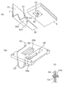
最後に、筐体後部3を筐体本体部2にスライド固着させるためのスライド固着手段の別の実施例につき図7により説明する。この実施例では、スライド部351a〜351dが筐体本体部2の底板部5に設けられており、該スライド部351a〜351dにスライド式に係合するスライド固着用突起部311a〜311dが、筐体後部3の屋根板部4から下方に延設された左右の脚部41a,41bの下縁に設けられている。例えば、図7(a)に見えるように、2つのスライド部351c,351dが形成されたスライド部材351が、底板部5の一端(一方の側板部6b寄りの箇所)に、ねじ止め等により取り付けられる。同様に、2つのスライド部351a,351bが形成されたもう1つのスライド部材が、底板部5の他端(他方の側板部6a寄りの箇所)に、ねじ止め等により取り付けられるが、図7(a)では側板部6aの陰になっているので見ることができず、番号351a,351bのみを参考のために付記しておく。各スライド部351a〜351dは、図5(a),(b)に示された前述のスライド部35aと同様に、大孔部(36a)、長孔部(37a)、テーパ面(39a)等の要素を含んで構成される。よって、これらの要素の詳細図示及び説明は図5及びその説明を援用するものとし、図7ではこれらの要素の詳細図示及び説明は省略する。
【0022】
屋根板部4の下面にて下向きに延びた脚部41a,41bの下縁は、内側に略直角に曲げられることで細長の水平部を成している。この脚部41a,41bの下縁の水平部において、下向きに、スライド固着用突起部311a〜311dが設けられている。脚部41bに設けられる1つのスライド固着用突起部311cを拡大して示すと図7(b)のようであり、図5(b)に示された前述のスライド固着用突起部31aと同様に、ねじ頭331c、間隙部321c、つば部341c等の要素を含んで構成される。スライド固着用突起部311cはナット312にねじ結合して脚部41bの下縁水平部に固定される。底板部5に設けられた4つのスライド部351a〜351dの配置にそれぞれ対応するように、屋根板部4の脚部41a,41bにおいて4つのスライド固着用突起部311a〜311dが設けられる。他のスライド固着用突起部311a,311b,311dは、図7(a)において陰になっているため明確には図示されてないが、突起部311cと同一の構成からなっている。
【0023】
図7の実施例において、筐体後部3を筐体本体部2に取り付ける際の、各スライド固着用突起部311a〜311dの各スライド部351a〜351dに対するスライド固着動作は、図5に示した実施例における各スライド固着用突起部31a〜31dの各スライド部35a〜35dに対するスライド固着動作と同様であるため、説明を省略する。つまり、テーパ面の存在によって、矢印X方向に筐体後部3が筐体本体部2に押し込まれていくほど、かたく結合するようになる。なお、スライド部351a〜351dの上面から側板部6a,6bの上縁までの距離D1と、スライド固着用突起部311a〜311dのつば部(341c)から屋根板部4の下面までの距離D2との関係は、適宜のクリアランスC分だけ、D1の方が長くなっている。つまり、D1=D2+Cである。これにより、屋根板部4が筐体本体部2の方に圧接され、かたい結合が得られる。
【0024】
スライド固着手段における孔部及びテーパ面を有するスライド部351a〜351dとスライド固着用突起部311a〜311dとの配置(図7参照)は、上記実施例とは逆であってもよい。すなわち、大孔部(36a)、長孔部(37a)、テーパ面(39a)等の要素(図5参照)を含んでなるスライド部351a〜351d(図7参照)を、屋根板部4側の脚部41a,41bの下縁水平部に設け、スライド固着用突起部311a〜311dを上向きにして底板部5側のスライド部材351に設けるようにしてもよい。また、図5の例のような側板部6a,6bの側にスライド部35a〜35dを設ける場合も同様に、スライド固着手段における孔部及びテーパ面を有するスライド部35a〜35dとスライド固着用突起部31a〜31dとの配置を、上記実施例とは逆にしてよい。すなわち、大孔部(36a)、長孔部(37a)、テーパ面(39a)等の要素を含んでなるスライド部35a〜35dを、屋根板部4側の下側に設け、スライド固着用突起部31a〜31dを上向きにして側板部6a,6bの上面に設けるようにしてよい。
【0025】
【発明の効果】
以上のように、本発明によると、筐体を見栄えよくかつ簡便に組み立てることができ、また筐体内部の保守点検もしやすい筐体構造を有する電子鍵盤楽器を提供できるとう優れた効果を奏する。
【図面の簡単な説明】
【図1】 (a)は本発明に係る電子鍵盤楽器の一実施例を示す平面図、(b)は同実施例に係る電子鍵盤楽器の背面図、(c)は同実施例に係る電子鍵盤楽器の底面図。
【図2】 同実施例に係る電子鍵盤楽器の筐体を筐体本体と筐体後部に分けた概略斜視図。
【図3】 同実施例に係る電子鍵盤楽器の筐体後部を説明するための図であって、(a)は筐体後部の立面図、(b)は筐体後部の下面図、(c)は筐体後部の側面図。
【図4】 同実施例に係る電子鍵盤楽器の筐体本体の平面図。
【図5】 同実施例に係る電子鍵盤楽器の筐体のスライド固着手段を説明するための図であって、(a)は図3に示した筐体本体の右側板部上面を拡大視した平面図、(b)は(a)のG−G線断面図。
【図6】 筐体後部と筐体本体の下方固定手段の他の実施例を説明するための図であって、(a)は下方固定手段の他の実施例を示す概略斜視図、(b)は(a)のパッチン嵌合係止部の一例を示す概略斜視図、(c)は係合突起63aが嵌合突起61の孔64に嵌合した状態を抽出して示す断面図。
【図7】 筐体後部を筐体本体部にスライド固着させるためのスライド固着手段の別の実施例を説明するための図であって、(a)は筐体本体と筐体後部に分けて略示する概略分解斜視図、(b)は筐体後部に設けられるスライド固着用突起部の側面図。
【符号の説明】
1 筐体
2 筐体本体部
3 筐体後部
4 屋根板部
5 底板部
6a,6b 側板部
7 背面板部
8 口棒部
9 鍵盤部
21a,21b,21c 結合保持板
31a〜31d,311a〜311d スライド固着用突起部
35a〜35d,351a〜351d スライド部[0001]
BACKGROUND OF THE INVENTION
The present invention relates to a housing structure for an electronic keyboard instrument.
[0002]
[Prior art]
In an electronic keyboard instrument having an overall flat board-like casing shape, the casing structure includes a bottom plate portion on which the keyboard portion is placed, a mouth bar portion located in front of the keyboard portion, and left and right sides of the keyboard portion. It is composed of left and right side plate parts located on the side, a roof plate part constituting the rear upper surface, and a back plate part. Generally, these plate parts are connected to each other via screws, etc. Is formed. However, in such a case configuration, the disassembly and reassembly work of the case when performing maintenance and inspection inside the case is troublesome.
On the other hand, Japanese Utility Model Laid-Open No. 62-103382 discloses an electronic keyboard musical instrument housing having a rear cover and a main body united with an upper surface part and a rear surface part, and a bottom plate part provided in the main body part. The rear cover is connected by a hinge so that the rear cover can be opened and closed. However, in this case, when assembling the casing, the final screw tightening for fixing the rear cover to the main body is always performed on the upper surface side of the casing. It was not preferable. Further, since the rear cover is not detachable from the housing main body, it is troublesome to assemble, and maintenance and inspection of the circuit board and the like inside the housing are difficult.
[0003]
In the electronic keyboard instrument of the above-described type, the main circuit board is disposed on the bottom plate in consideration of ease of maintenance and inspection. However, when the main circuit board is provided on the bottom plate portion behind the keyboard portion, the size of the bottom plate portion in the front-rear direction must be increased, and the size of the musical instrument in the front-rear direction is increased. Further, when the main circuit board is provided on the bottom plate part below the keyboard part, the thickness of the instrument in the vertical direction increases.
[0004]
[Problem to be Solved by the Invention]
SUMMARY OF THE INVENTION The present invention has been made in view of the above points, and an object of the present invention is to provide an electronic keyboard instrument having a casing structure that can be easily and easily assembled and can be easily maintained and inspected. It is.
[0005]
[Means for solving the problems]
The present invention relates to an electronic keyboard instrument comprising a keyboard portion and a housing in which the keyboard portion is disposed, wherein the housing includes a bottom plate portion, a side plate portion, a back plate portion, and a roof plate portion, and the bottom plate The keyboard part is placed on the part, and the second casing part including at least the roof panel part and the back panel part can be attached to and detached from the first casing part including at least the bottom plate part, The side plate part belongs to either the first or second housing part, and the second housing part has coupling holding means. And has a lower edge portion bent inward at the back plate portion. Then, the lower end portion of the coupling holding means is positioned on the upper surface of the bottom plate portion, and the second casing portion is slidably attached to the first casing portion, so that the first casing portion The bottom plate portion is sandwiched between the coupling holding means of the second casing portion and the back plate portion, and the second casing portion is fixed in the sandwiched state to fix the second casing portion to the first casing. The casing is configured to be detachably attached to a body part, and circuit components of the electronic keyboard instrument are attached to the inside of the back plate. According to this, the lower end portion of the coupling holding means on the second housing portion side is positioned on the upper surface of the bottom plate portion on the first housing portion side, and the second housing portion is placed on the first housing. Since the configuration is such that the second casing portion is slid and mounted, even if there is a heavy object in the second casing portion, it can be securely held and attached and fixed, and the first casing portion can be fixed. Since the bottom plate portion on the side is sandwiched between the coupling holding means on the second housing portion side and the back plate portion, and fixed in this sandwiched state, the first housing portion and the second housing portion On the other hand, it is difficult to separate, and on the other hand, since it can be easily detached, it is possible to provide an excellent housing structure that facilitates internal maintenance and inspection. Further, since the circuit components of the electronic keyboard instrument are attached to the inside of the back plate portion, the circuit components on the inside of the back plate portion are simply slid in a relatively small amount in the removing direction. There is an advantage that the attachment state can be confirmed and maintenance inspection is easy.
[0007]
DETAILED DESCRIPTION OF THE INVENTION
Hereinafter, an embodiment of the present invention will be described with reference to the accompanying drawings.
FIG. 1A is a plan view showing an example of an electronic keyboard instrument according to the present invention. FIG. 1B is a rear view thereof, and FIG. 1C is a bottom view thereof. The casing 1 of the electronic keyboard instrument according to the present embodiment is roughly divided into a casing
[0008]
Attachment of the housing
[0009]
First, a specific example of the housing
[0010]
As shown in FIG. 3 (b), slide fixing means for slidingly fixing the housing
[0011]
Next, an example of the constituent elements of the slide fixing means provided on the left and right
[0012]
In order to attach the housing
[0013]
[0014]
As shown in FIG. 5B,
[0015]
In addition to the coupling by the above-mentioned slide fixing means, the casing
[0016]
As shown in FIG. 3C, the
[0017]
In order to remove the housing
[0018]
Returning to FIG. 3,
In the above-described embodiment, the left and right
[0019]
In the above example, the rear lower end portion of the housing
When the
In the elastic
When such two elastic deformation fitting means (the elastic
[0020]
Note that the slide fixing means is not limited to the above-described type, and any mechanism may be used as long as the casing
Moreover, in the above-mentioned Example, although the
When only the configuration in which the main circuit portion or the like is provided in the housing
[0021]
Finally, another embodiment of the slide fixing means for slidingly fixing the
[0022]
The lower edges of the
[0023]
In the embodiment shown in FIG. 7, the slide fixing operation of the
[0024]
The arrangement (see FIG. 7) of the
[0025]
【The invention's effect】
As described above, according to the present invention, it is possible to provide an electronic keyboard instrument having a housing structure that can be easily and easily assembled and can be easily maintained and inspected.
[Brief description of the drawings]
1A is a plan view showing one embodiment of an electronic keyboard instrument according to the present invention, FIG. 1B is a rear view of the electronic keyboard instrument according to the embodiment, and FIG. 1C is an electronic diagram according to the embodiment. The bottom view of a keyboard instrument.
FIG. 2 is a schematic perspective view in which a casing of the electronic keyboard instrument according to the embodiment is divided into a casing body and a rear portion of the casing.
FIGS. 3A and 3B are diagrams for explaining the rear part of the casing of the electronic keyboard instrument according to the embodiment, where FIG. 3A is an elevation view of the rear part of the casing, FIG. 3B is a bottom view of the rear part of the casing; c) Side view of the rear part of the housing.
FIG. 4 is a plan view of a casing body of the electronic keyboard instrument according to the embodiment.
FIG. 5 is a view for explaining a slide fixing means of the casing of the electronic keyboard instrument according to the embodiment, wherein (a) is an enlarged view of the upper surface of the right side plate portion of the casing body shown in FIG. 3; The top view, (b) is the GG sectional view taken on the line of (a).
6A and 6B are diagrams for explaining another embodiment of the lower fixing means for the rear portion of the casing and the casing main body, and FIG. 6A is a schematic perspective view showing another embodiment of the lower fixing means; (A) is a schematic perspective view which shows an example of the patchon fitting locking part of (a), (c) is sectional drawing which extracts and shows the state which the
FIG. 7 is a diagram for explaining another embodiment of the slide fixing means for slidingly fixing the rear portion of the housing to the main body portion of the case, and (a) is divided into the main body of the case and the rear portion of the case. The schematic exploded perspective view to show schematically, (b) is a side view of the protrusion part for slide fixation provided in a housing | casing rear part.
[Explanation of symbols]
1 housing
2 Case body
3 Rear case
4 Roof plate
5 Bottom plate
6a, 6b Side plate
7 Back plate
8 mouth stick
9 Keyboard
21a, 21b, 21c coupling holding plate
31a to 31d, 311a to 311d Slide fixing protrusion
35a-35d, 351a-351d Slide part
Claims (2)
前記筐体は、底板部と側板部と背面板部と屋根板部とを有し、前記底板部に前記鍵盤部が載置され、少なくとも前記底板部を含む第1の筐体部分に対して少なくとも前記屋根板部と前記背面板部とを含む第2の筐体部分が着脱可能であり、前記側板部は前記第1又は第2の筐体部分のいずれかに帰属し、
前記第2の筐体部分に結合保持手段を有すると共に、前記背面板部において内側に折れ曲がった下縁部を有し、該結合保持手段の下端部を前記底板部の上面に位置させて前記第2の筐体部分を前記第1の筐体部分に対してスライド装着することで前記第1の筐体部分の前記底板部を前記第2の筐体部分の前記結合保持手段と前記背面板部の前記下縁部との間に挟み込み、この挟み込まれた状態で固着することにより該第2の筐体部分を該第1の筐体部分に対して着脱式に取り付けてなる前記筐体を構成するようにしてなり、かつ、前記背面板部の内側に当該電子鍵盤楽器の回路部品が取り付けられていることを特徴とする電子鍵盤楽器。In an electronic keyboard instrument comprising a keyboard part and a housing in which the keyboard part is arranged,
The housing includes a bottom plate portion, a side plate portion, a back plate portion, and a roof plate portion, the keyboard portion is placed on the bottom plate portion, and at least a first case portion including the bottom plate portion. A second housing part including at least the roof plate part and the back plate part is detachable, and the side plate part belongs to either the first or second housing part,
While organic coupling holding means to said second housing portion, have a lower edge which is bent inwardly at said back plate portion, said lower end portion of the coupling holding means is positioned on the upper surface of the bottom plate portion The bottom plate portion of the first casing portion is slidably attached to the first casing portion so that the bottom holding portion of the first casing portion and the back plate are connected to the second casing portion. The housing formed by detachably attaching the second housing portion to the first housing portion by being sandwiched between the lower edge portion of the portion and being fixed in the sandwiched state. An electronic keyboard instrument comprising: a circuit component of the electronic keyboard instrument, wherein the electronic keyboard instrument circuit component is attached to the inside of the back plate portion.
Priority Applications (1)
| Application Number | Priority Date | Filing Date | Title |
|---|---|---|---|
| JP2002255421A JP3765295B2 (en) | 2001-09-19 | 2002-08-30 | Electronic keyboard instrument |
Applications Claiming Priority (3)
| Application Number | Priority Date | Filing Date | Title |
|---|---|---|---|
| JP2001285072 | 2001-09-19 | ||
| JP2001-285072 | 2001-09-19 | ||
| JP2002255421A JP3765295B2 (en) | 2001-09-19 | 2002-08-30 | Electronic keyboard instrument |
Related Child Applications (2)
| Application Number | Title | Priority Date | Filing Date |
|---|---|---|---|
| JP2004089745A Division JP4023466B2 (en) | 2001-09-19 | 2004-03-25 | Electronic keyboard instrument |
| JP2004089746A Division JP3976023B2 (en) | 2001-09-19 | 2004-03-25 | Electronic keyboard instrument |
Publications (3)
| Publication Number | Publication Date |
|---|---|
| JP2003167581A JP2003167581A (en) | 2003-06-13 |
| JP2003167581A5 JP2003167581A5 (en) | 2005-03-03 |
| JP3765295B2 true JP3765295B2 (en) | 2006-04-12 |
Family
ID=26622500
Family Applications (1)
| Application Number | Title | Priority Date | Filing Date |
|---|---|---|---|
| JP2002255421A Expired - Fee Related JP3765295B2 (en) | 2001-09-19 | 2002-08-30 | Electronic keyboard instrument |
Country Status (1)
| Country | Link |
|---|---|
| JP (1) | JP3765295B2 (en) |
Families Citing this family (4)
| Publication number | Priority date | Publication date | Assignee | Title |
|---|---|---|---|---|
| JP4644460B2 (en) * | 2004-09-24 | 2011-03-02 | 株式会社河合楽器製作所 | Keyboard instrument stand |
| JP5034493B2 (en) * | 2006-12-27 | 2012-09-26 | ヤマハ株式会社 | Electronic keyboard instrument housing structure |
| JP5453979B2 (en) * | 2009-07-23 | 2014-03-26 | ヤマハ株式会社 | Electronic keyboard instrument housing structure |
| CN110288961B (en) * | 2019-06-03 | 2021-05-07 | 湖南城市学院 | Piano keyboard adjusting device and adjusting method using same |
-
2002
- 2002-08-30 JP JP2002255421A patent/JP3765295B2/en not_active Expired - Fee Related
Also Published As
| Publication number | Publication date |
|---|---|
| JP2003167581A (en) | 2003-06-13 |
Similar Documents
| Publication | Publication Date | Title |
|---|---|---|
| US7348477B2 (en) | Electronic keyboard musical instrument | |
| JP4817735B2 (en) | Game machine frame | |
| JP3765295B2 (en) | Electronic keyboard instrument | |
| US10969831B2 (en) | Keyboard device and electronic apparatus | |
| JP4023466B2 (en) | Electronic keyboard instrument | |
| JP4162031B2 (en) | Electronic keyboard instrument | |
| JP3976023B2 (en) | Electronic keyboard instrument | |
| JP5063809B2 (en) | Assembly structure for panel | |
| JP4899870B2 (en) | Electronic keyboard instrument exterior structure | |
| KR20000060320A (en) | Disk drive apparatus | |
| JP3604978B2 (en) | Inspection port frame material and inspection port frame using the same | |
| JP4135296B2 (en) | Keyboard device | |
| JP5051199B2 (en) | Keyboard instrument case structure | |
| JP4407578B2 (en) | Keyboard instrument case structure | |
| JP2501817Y2 (en) | Electronic device housing structure | |
| JP3189821B2 (en) | Keyboard device | |
| JP3513899B2 (en) | Display device mounting structure | |
| JP4469696B2 (en) | Component joint structure and electronic equipment | |
| KR100572978B1 (en) | Connecting piece and connecting structure for panel using the same | |
| JPH03174192A (en) | Keyboard device | |
| JP2780709B2 (en) | Keyboard device | |
| JP2000148146A (en) | Master panel mounting structure of electronic musical instrument | |
| JP3116829U (en) | Electronics cabinet | |
| JP2011027919A (en) | Housing structure for electronic keyboard musical instrument | |
| JP2001284843A (en) | Metal case for electronic part mounted board |
Legal Events
| Date | Code | Title | Description |
|---|---|---|---|
| A521 | Written amendment |
Free format text: JAPANESE INTERMEDIATE CODE: A523 Effective date: 20040330 |
|
| A621 | Written request for application examination |
Free format text: JAPANESE INTERMEDIATE CODE: A621 Effective date: 20040917 |
|
| A871 | Explanation of circumstances concerning accelerated examination |
Free format text: JAPANESE INTERMEDIATE CODE: A871 Effective date: 20041222 |
|
| A975 | Report on accelerated examination |
Free format text: JAPANESE INTERMEDIATE CODE: A971005 Effective date: 20050117 |
|
| A977 | Report on retrieval |
Free format text: JAPANESE INTERMEDIATE CODE: A971007 Effective date: 20050405 |
|
| A131 | Notification of reasons for refusal |
Free format text: JAPANESE INTERMEDIATE CODE: A131 Effective date: 20050419 |
|
| A521 | Written amendment |
Free format text: JAPANESE INTERMEDIATE CODE: A523 Effective date: 20050620 |
|
| A131 | Notification of reasons for refusal |
Free format text: JAPANESE INTERMEDIATE CODE: A131 Effective date: 20050809 |
|
| A521 | Written amendment |
Free format text: JAPANESE INTERMEDIATE CODE: A523 Effective date: 20051007 |
|
| TRDD | Decision of grant or rejection written | ||
| A01 | Written decision to grant a patent or to grant a registration (utility model) |
Free format text: JAPANESE INTERMEDIATE CODE: A01 Effective date: 20060104 |
|
| A61 | First payment of annual fees (during grant procedure) |
Free format text: JAPANESE INTERMEDIATE CODE: A61 Effective date: 20060117 |
|
| R150 | Certificate of patent or registration of utility model |
Free format text: JAPANESE INTERMEDIATE CODE: R150 Ref document number: 3765295 Country of ref document: JP Free format text: JAPANESE INTERMEDIATE CODE: R150 |
|
| S531 | Written request for registration of change of domicile |
Free format text: JAPANESE INTERMEDIATE CODE: R313532 |
|
| R350 | Written notification of registration of transfer |
Free format text: JAPANESE INTERMEDIATE CODE: R350 |
|
| FPAY | Renewal fee payment (event date is renewal date of database) |
Free format text: PAYMENT UNTIL: 20090203 Year of fee payment: 3 |
|
| FPAY | Renewal fee payment (event date is renewal date of database) |
Free format text: PAYMENT UNTIL: 20100203 Year of fee payment: 4 |
|
| FPAY | Renewal fee payment (event date is renewal date of database) |
Free format text: PAYMENT UNTIL: 20110203 Year of fee payment: 5 |
|
| FPAY | Renewal fee payment (event date is renewal date of database) |
Free format text: PAYMENT UNTIL: 20120203 Year of fee payment: 6 |
|
| FPAY | Renewal fee payment (event date is renewal date of database) |
Free format text: PAYMENT UNTIL: 20130203 Year of fee payment: 7 |
|
| FPAY | Renewal fee payment (event date is renewal date of database) |
Free format text: PAYMENT UNTIL: 20140203 Year of fee payment: 8 |
|
| LAPS | Cancellation because of no payment of annual fees |