JP3764591B2 - Absorbing device for expansion water from main water heater - Google Patents
Absorbing device for expansion water from main water heater Download PDFInfo
- Publication number
- JP3764591B2 JP3764591B2 JP23775698A JP23775698A JP3764591B2 JP 3764591 B2 JP3764591 B2 JP 3764591B2 JP 23775698 A JP23775698 A JP 23775698A JP 23775698 A JP23775698 A JP 23775698A JP 3764591 B2 JP3764591 B2 JP 3764591B2
- Authority
- JP
- Japan
- Prior art keywords
- water
- expansion
- heater
- supply pipe
- water heater
- Prior art date
- Legal status (The legal status is an assumption and is not a legal conclusion. Google has not performed a legal analysis and makes no representation as to the accuracy of the status listed.)
- Expired - Fee Related
Links
- XLYOFNOQVPJJNP-UHFFFAOYSA-N water Substances O XLYOFNOQVPJJNP-UHFFFAOYSA-N 0.000 title claims description 304
- 238000007599 discharging Methods 0.000 description 4
- 238000010586 diagram Methods 0.000 description 3
- 238000000034 method Methods 0.000 description 3
- 238000011144 upstream manufacturing Methods 0.000 description 3
- 230000005484 gravity Effects 0.000 description 2
- 238000010438 heat treatment Methods 0.000 description 2
- 230000002093 peripheral effect Effects 0.000 description 2
- 230000008602 contraction Effects 0.000 description 1
- 230000000694 effects Effects 0.000 description 1
- 238000005406 washing Methods 0.000 description 1
Images


Classifications
-
- F—MECHANICAL ENGINEERING; LIGHTING; HEATING; WEAPONS; BLASTING
- F16—ENGINEERING ELEMENTS AND UNITS; GENERAL MEASURES FOR PRODUCING AND MAINTAINING EFFECTIVE FUNCTIONING OF MACHINES OR INSTALLATIONS; THERMAL INSULATION IN GENERAL
- F16L—PIPES; JOINTS OR FITTINGS FOR PIPES; SUPPORTS FOR PIPES, CABLES OR PROTECTIVE TUBING; MEANS FOR THERMAL INSULATION IN GENERAL
- F16L55/00—Devices or appurtenances for use in, or in connection with, pipes or pipe systems
Landscapes
- Engineering & Computer Science (AREA)
- General Engineering & Computer Science (AREA)
- Mechanical Engineering (AREA)
- Steam Or Hot-Water Central Heating Systems (AREA)
- Domestic Hot-Water Supply Systems And Details Of Heating Systems (AREA)
Description
【0001】
【発明の属する技術分野】
この発明は元止式温水器からの膨張水を吸収する装置に関する。
【0002】
【従来の技術】
従来、給湯器で沸かし上げた温水を配管を通じて供給し、吐水部から吐出させるといったことが広く行われている。
この場合、一般に給湯器は温水の吐水部から遠く離れた箇所に設置されているのが通例で、このため吐水部から温水吐水を行ったときに先ず長い配管内の冷たい水が吐水されてしまい、なかなか求める温度の温水が出て来ないといった問題があった。
【0003】
そこで温水吐水部に近い位置、例えば洗面化粧台のキャビネット内部やキッチンキャビネットの内部に温水器を設置しておいてそこで所定量の温水を貯えておき、吐水部を吐水操作したときにその温水器内部の温水を吐水部に供給してそこから速やかに温水を吐水可能とすることが考えられている。
【0004】
この温水器を用いた温水供給方式として、温水器の下流側で流路を閉鎖する先止式と、温水器の上流側で流路を閉鎖する元止式とがある。
図5は後者の方式、即ち元止式の場合の一例を示したものである。
【0005】
同図において200は洗面化粧台のキャビネット,キッチンキャビネット等の内部に設置された電気温水器で内部に電気ヒータ202が備えられており、その電気ヒータ202の加熱により水を温水化するようになっている。
204は温水の吐水部としての水栓であって、水側のハンドル206Aと湯側のハンドル206B及び吐水管208を備えている。
【0006】
この例の温水供給方式の場合、給水源からの水は水の供給管210を通じて一旦水栓204へと供給される。水栓204に供給された水はハンドル操作により水栓204を経由して水栓204から延び出した供給管212を通じ電気温水器200へと導かれ、そこで電気ヒータ202の加熱作用で温水化される。
【0007】
そしてその電気温水器200内部に予め貯えられた温水が電気温水器200から延び出す温水の供給管214を通じて水栓204へと供給され、水栓204のハンドル操作により吐水管208の先端から吐水される。
【0008】
ところでこのように電気温水器200で予め水を温水化しておいて吐水部としての水栓204に供給するようになした場合、電気温水器200で膨張水が発生する。
従ってその膨張水を何らかの手段で電気温水器200外へと逃してやる必要がある。
【0009】
而して図5に示す元止式電気温水器200からの温水供給方式の場合、水栓204の湯側ハンドル206Bを完全閉鎖できない構造となしておいて、電気温水器200からの膨張水を供給管214を通じて水栓204へと導き、更に吐水管208から外部へと逃すようにしていた。
【0010】
【発明が解決しようとする課題】
しかしながらこのように電気温水器200からの膨張水を水栓204の吐水管208を通じて外部に逃すようにした場合、水栓204のハンドル206A,206Bを閉操作しているにも拘らず吐水管208から加熱された温水が滴り落ちる現象が生じ、あたかも水栓204が止水不良であるかのような感じを与えてしまい、見苦しさを感じさせてしまう。
【0011】
またその他に、温水の吐水を停止した後時間の経過とともに供給管214内部の温水が冷却され、その後に水栓204から温水を吐水させる際に当初供給管214内部で冷却された冷たい水が出てしまって使用者に不快感を与えてしまうとともに、その冷たい水が無駄に捨てられる死に水となってしまうといった問題があった。
【0012】
【課題を解決するための手段】
本願の発明の膨張水の吸収装置はこのような課題を解決するために案出されたものである。
而して請求項1のものは、元止式温水器からの膨張水を吸収する装置であって、前記温水器への給水を止める止水部と該温水器からの温水を吐水する吐水部との間の流路に、該温水器からの膨張水を導入させて吸収する膨張水タンクを該流路に連通する状態で接続し、且つ少なくとも該膨張水タンクをその底部が該吐水部よりも低くなる位置に設けたことを特徴とする。
【0013】
請求項2のものは、請求項1に記載の元止式温水器からの膨張水の吸収装置において、前記膨張水タンクの前記流路への接続部位に、該流路の流れによって該膨張水タンク内に吸収した膨張水を該流路に吸い出すアスピレータを設けたことを特徴とする。
【0014】
【作用及び発明の効果】
上記のように請求項1の膨張水の吸収装置は、止水部と温水器との間の流路に、温水器からの膨張水を導入させて吸収する膨張水タンクを接続したもので、この膨張水の吸収装置によれば、温水器で膨張水が生じたときその膨張水を流路上に設けた膨張水タンク内に逃すことができる。
従ってこの請求項1によれば、温水器で発生した膨張水が配管を通じて吐水部に到り、その吐水部から外部に滴り落ちるといった現象を防止でき、あたかも吐水部が止水不良であるかのような感じを与えてしまうといった不都合を解消することができる。
【0015】
上記膨張水タンクは、その他に次のような働きも有する。
即ち、従来にあっては吐水部から温水を吐水させる際に、温水器とその吐水部との間の配管内で冷却された水が吐水初期に出てしまうといった問題が生じていたが、上記のような膨張水タンクを設けた場合、温水器と吐水部との間の配管内の温水ないし水がその配管と連通状態にある膨張水タンク内部に重力の作用で流れ込み、同配管内が部分的若しくは全体的に空の状態となる。
【0016】
従って次に吐水部から温水を吐水させようとしたときに吐水初期において吐水部からの冷水の吐水を無くし或いは少なくすることができる。
これにより無駄に捨てられてしまうこととなる死に水(冷水)を無くし或いは少なくすることができ、また併せて使用者に冷水の吐水によって不快感を与えてしまうといった問題を解決することができる。
【0017】
次に請求項2の膨張水の吸収装置は、流路への膨張水タンクの接続部位にアスピレータを設けたもので、このようにしておけば、止水部を開いて流路内に水の流れを生ぜしめたときに、その水の流れによってアスピレータの作用により、膨張水タンクに一旦吸収した膨張水を再び流路内へと吸い出すことができる。
【0018】
【実施例】
次に本発明の実施例を図面に基づいて詳しく説明する。
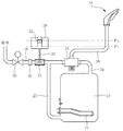
図1において、10は電気温水器であって内部に電気ヒータ12が備えられており、電気温水器10内部に導かれた水がその電気ヒータ12の加熱作用で温水化され且つ保温されるようになっている。
14は自動水栓の吐水部(温水の吐水部)で、16はその自動水栓におけるミキシングバルブであり、ここで水と湯とを所定比率で混合し吐水部14へと送るようになっている。
【0019】
18は給水源からの水を上記電気温水器10又は自動水栓の吐水部14へと供給するための供給管で、その先端が上記ミキシングバルブ16に接続されている。
またこの供給管18上には、上記電気温水器10の上流部位で流路を開閉する電磁弁(止水部)20が設けられている。
【0020】
22は供給管18を通じて送られてきた水を電気温水器10へと導く供給管で、供給管18から分岐して延び、その先端が電気温水器10の底部に接続されている。
一方電気温水器10の上部からは、温水を取り出すための供給管24が延び出しており、その先端がミキシングバルブ16に接続されている。
【0021】
そしてこのミキシングバルブ16において、供給管24を通じて取り出された電気温水器10内の温水と、供給管18を通じて供給された水とが所定比率に混合される。
このミキシングバルブ16からは水若しくは温水又は温水と水との混合水を上記吐水部14へと供給する供給管26が延び出しており、その先端がかかる吐水部14に接続されている。
【0022】
供給管18には上記電磁弁20の下流部且つ供給管22の上流部において、膨張水タンク28が連通管30を介して接続されている。
この膨張水タンク28は、電気温水器10からの膨張水を導入させて吸収するためのもので、その全体が上記自動水栓における吐水部14よりも下の位置に位置させられている。
【0023】
尚、32は膨張水タンク28内の水が外部に漏出するのを防止するための逆止フロート弁である。
この逆止フロート弁32は、膨張水タンク28内の水の水位とともに上昇し、膨張水タンク28内が一定満水量になると弁座に当接して膨張水タンク28の開口を閉鎖する。
【0024】
供給管18における膨張水タンク28の接続部位、詳しくは連通管30の接続部位には、アスピレータ34が設けられている。
このアスピレータ34は、供給管18内の水の流れによって膨張水タンク28内に吸収保持されている膨張水を供給管18側に吸い出す作用をなすものである。
【0025】
尚、このアスピレータ34と上記電磁弁20との間には流量調整弁36が設けられている。
この流量調整弁36は、電気温水器10への水の供給流量を抑制し、電気温水器10に対して多量の水が流れ過ぎるのを防止する働きをなすものである。
【0026】
本例においては、自動水栓における吐水部14に設けてあるセンサが差し出された手を検知すると電磁弁20が開かれ、これにより供給管18を通じて送られてきた水と電気温水器10からの温水とがミキシングバルブ16で混合された上、供給管26を通じて吐水部14へと送られ、その吐水部14から吐水される。
また一方、手洗いの終了によって吐水部14に設けたセンサが手を検知しなくなると電磁弁20が閉鎖され、吐水部14からの吐水が停止する。
【0027】
本例の膨張水の吸収装置の場合、吐水部14から吐水が行われているとき、膨張水タンク28の内部は空の状態にある。
一方吐水部14からの吐水が停止すると、供給管26内の温水若しくは水の一部が電気温水器10,供給管22を経て、或いは更にミキシングバルブ16に接続された供給管18を直接伝ってアスピレータ34,連通管30を介し膨張水タンク28内部に流れ込む。
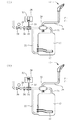
そして供給管26内の温水ないし水の水位と膨張水タンク28内の水位とが丁度釣り合った位置(図2(I)中P1)で供給管26からの膨張水タンク28への温水ないし水の流れが停止する。
【0028】
その後において電気温水器10で膨張水が発生すると、その膨張水が同じく供給管22或いはミキシングバルブ16を経て膨張水タンク28内に導入され、そこで電気温水器10からの膨張水が吸収される。
【0029】
このとき、発生した膨張水は吐水部14につながる供給管26側へも一部流出する。
図2(II)中釣合い位置P2は、膨張水流出後における膨張水タンク28内の水位と供給管26内の水位との釣合い位置を示している。
【0030】
以上のような本例の膨張水の吸収装置では、電気温水器10で膨張水が生じたときその膨張水を電気温水器10と電磁弁20との間の流路を通じて膨張水タンク28内に逃すことができる。
従って電気温水器10で発生した膨張水が供給管26を通じて吐水部14に到り、その吐水部14から滴り落ちるといったことがなく、従来のようにあたかも吐水部14が止水不良であるかのような感じを与えてしまうといったことがない。
【0031】
また従来にあっては吐水部14から温水を吐水させる際に、電気温水器10とその吐水部14との間の供給管26内で冷却され水が吐水初期に出てしまうといった問題が生じていたが、本例では膨張水タンク28を設けていることから、しかもその膨張水タンク28は全体的に吐水部14よりも低い位置に設けてあることから、電気温水器10と吐水部14との間の供給管26内の温水ないし水が重力の作用で膨張水タンク28内部に流れ込み、これにより供給管26内が部分的に空の状態となる。
従って次に吐水部14から温水を吐水させようとしたときに、吐水初期において吐水部14からの冷水の吐水を効果的に少なくすることができる。
【0032】
加えて本例の膨張水の吸収装置は、供給管18への膨張水タンク28の接続部位にアスピレータ34を設けているため、電磁弁20を開いて供給管18内に水の流れが生じたときに、その水の流れによってアスピレータ34の作用により膨張水タンク28内の水を再び供給管18内へと吸い出すことができる。
【0033】
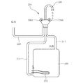
図3は膨張水タンク28を全体的に低く配設し且つその内容量を、供給管26内の温水ないし水の全体を吸収可能な大きさとなしたもので、この例の場合、吐水部14からの吐水終了時に供給管26内部の温水ないし水を全体的に膨張水タンク28内に流入させ、同供給管26内をほぼ完全に空の状態となすことができる。
このようにしておけば、吐水部14からの温水の吐水初期に冷たい水が出てしまうといった問題をほぼ完全に解決することができる。
【0034】
以上本発明の実施例を詳述したがこれはあくまで一例示である。
例えば上記実施例では電気温水器10からの温水を自動水栓の吐水部14から吐水させる場合に適用した場合の例であるが、他の形態の吐水部から温水を吐水するに際しても本発明を適用可能であるし、或いはまた膨張水タンク28として他の様々な形態のものを用いることができる。
【0035】
例えば図4に示しているように、蛇腹部38の伸縮によって膨張水を吸収する形態の膨張水タンク28となすこともできるし、或いはその他の形態とすることもできる。
その他本発明はその主旨を逸脱しない範囲において種々変更を加えた形態で構成可能である。
【図面の簡単な説明】
【図1】本発明の一実施例である膨張水の吸収装置を周辺部とともに示す図である。
【図2】図1の実施例の作用説明図である。
【図3】本発明の他の実施例の膨張水の吸収装置を周辺部とともに示す図である。
【図4】本発明の他の実施例における膨張水タンクの形態例を示す図である。
【図5】本発明の背景説明のための説明図である。
【符号の説明】
10 電気温水器
14 吐水部
18,22,24,26 供給管
20 電磁弁(止水部)
28 膨張水タンク
34 アスピレータ[0001]
BACKGROUND OF THE INVENTION
The present invention relates to an apparatus that absorbs expanded water from a water heater.
[0002]
[Prior art]
Conventionally, hot water boiled by a water heater is supplied through a pipe and discharged from a water discharge section.
In this case, the water heater is generally installed at a location far away from the hot water spouting portion. Therefore, when hot water is discharged from the water spouting portion, cold water in the long pipe is first discharged. There was a problem that hot water of the desired temperature did not come out easily.
[0003]
Therefore, when a water heater is installed at a position close to the hot water spouting section, for example, inside the cabinet of the bathroom vanity or inside the kitchen cabinet, a predetermined amount of hot water is stored there, and when the water discharging section is spouted, the water heater It is considered that the hot water inside can be supplied to the water discharge section so that the hot water can be discharged quickly.
[0004]
As a hot water supply method using this water heater, there are a leading type that closes the channel on the downstream side of the water heater and a non-stop type that closes the channel on the upstream side of the water heater.
FIG. 5 shows an example of the latter method, that is, the case of the original stop type.
[0005]
In the figure,
[0006]
In the case of the hot water supply system in this example, water from the water supply source is temporarily supplied to the
[0007]
The hot water stored in the
[0008]
By the way, when water is warmed in advance by the
Therefore, it is necessary to let the expanded water escape to the outside of the
[0009]
Thus, in the case of the hot water supply method from the main
[0010]
[Problems to be solved by the invention]
However, when the expansion water from the
[0011]
In addition, the hot water in the
[0012]
[Means for Solving the Problems]
The inflating water absorbing device of the present invention has been devised to solve such problems.
Thus, according to the first aspect of the present invention, there is provided a device that absorbs the expanded water from the main water heater, a water stop portion that stops water supply to the water heater, and a water discharge portion that discharges the hot water from the water heater. An expansion water tank that introduces and absorbs expansion water from the water heater is connected to the flow path between the flow path and the flow path, and at least the bottom of the expansion water tank is connected to the discharge section from the water discharge section. It is characterized by being provided at a lower position.
[0013]
According to a second aspect of the present invention, there is provided an apparatus for absorbing the expansion water from the main water heater according to the first aspect, wherein the expansion water is connected to the flow path of the expansion water tank by the flow of the flow path. An aspirator for sucking the expanded water absorbed in the tank into the flow path is provided.
[0014]
[Operation and effect of the invention]
As described above, the apparatus for absorbing expansion water according to
Therefore, according to the first aspect, it is possible to prevent a phenomenon in which the expanded water generated in the water heater reaches the water discharge part through the pipe and dripping down from the water discharge part, and it is as if the water discharge part has a poor water stoppage. The inconvenience of giving such a feeling can be solved.
[0015]
The expanded water tank also has the following functions.
That is, in the past, when warm water was discharged from the water discharger, there was a problem that the water cooled in the pipe between the water heater and the water discharger was discharged in the initial stage of water discharge. When the expansion water tank is installed, the hot water or water in the pipe between the water heater and the water discharge part flows into the expansion water tank in communication with the pipe by the action of gravity, and the inside of the pipe is partially Or totally empty.
[0016]
Therefore, when the hot water is discharged from the water discharge portion next time, it is possible to eliminate or reduce the amount of cold water discharged from the water discharge portion in the early stage of water discharge.
Accordingly, it is possible to eliminate or reduce the amount of water (cold water) that will be thrown away unnecessarily, and to solve the problem that the user feels uncomfortable by discharging the cold water.
[0017]
Next, the apparatus for absorbing expansion water according to claim 2 is provided with an aspirator at the connection site of the expansion water tank to the flow path. When the flow is generated, the expanded water once absorbed in the expanded water tank can be sucked back into the flow path by the action of the aspirator by the flow of the water.
[0018]
【Example】
Next, embodiments of the present invention will be described in detail with reference to the drawings.
In FIG. 1,
[0019]
On the
[0020]
On the other hand, a
[0021]
In the mixing
From this mixing
[0022]
An
The
[0023]
The
[0024]
An
The
[0025]
A flow
The flow
[0026]
In this example, the
On the other hand, when the sensor provided in the
[0027]
In the case of the expansion water absorbing device of this example, when water is discharged from the
On the other hand, when the water discharge from the
Then, hot water or water from the
[0028]
Thereafter, when expansion water is generated in the
[0029]
At this time, the generated expanded water partially flows out to the
Figure 2 (II) in the balance position P 2 indicates the balance position of the water level in the expansion water tank level and the
[0030]
In the expansion water absorbing device of this example as described above, when expansion water is generated in the
Therefore, the expansion water generated in the
[0031]
Further, conventionally, when warm water is discharged from the
Therefore, when the hot water is discharged from the
[0032]
In addition, since the
[0033]
FIG. 3 shows an arrangement in which the
If it does in this way, the problem that cold water will come out at the time of the warm water discharge from the
[0034]
Although the embodiment of the present invention has been described in detail above, this is merely an example.
For example, although the above embodiment is an example in the case where the hot water from the
[0035]
For example, as shown in FIG. 4, the
In addition, this invention can be comprised in the form which added the various change in the range which does not deviate from the main point.
[Brief description of the drawings]
FIG. 1 is a view showing an expansion water absorbing device according to an embodiment of the present invention together with peripheral portions.
FIG. 2 is an operation explanatory diagram of the embodiment of FIG.
FIG. 3 is a view showing an expansion water absorbing device according to another embodiment of the present invention together with a peripheral portion.
FIG. 4 is a diagram showing an example of an expanded water tank according to another embodiment of the present invention.
FIG. 5 is an explanatory diagram for explaining the background of the present invention.
[Explanation of symbols]
DESCRIPTION OF
28
Claims (2)
前記温水器への給水を止める止水部と該温水器からの温水を吐水する吐水部との間の流路に、該温水器からの膨張水を導入させて吸収する膨張水タンクを該流路に連通する状態で接続し、且つ少なくとも該膨張水タンクをその底部が該吐水部よりも低くなる位置に設けたことを特徴とする元止式温水器からの膨張水の吸収装置。A device that absorbs the expanded water from the original water heater,
An expansion water tank that introduces and absorbs expansion water from the water heater into a flow path between a water stop portion that stops water supply to the water heater and a water discharge portion that discharges hot water from the water heater. An apparatus for absorbing expansion water from a main water heater, wherein the expansion water tank is connected in a state communicating with a road and at least the expansion water tank is provided at a position where the bottom of the expansion water tank is lower than the water discharge section.
Priority Applications (1)
| Application Number | Priority Date | Filing Date | Title |
|---|---|---|---|
| JP23775698A JP3764591B2 (en) | 1998-08-24 | 1998-08-24 | Absorbing device for expansion water from main water heater |
Applications Claiming Priority (1)
| Application Number | Priority Date | Filing Date | Title |
|---|---|---|---|
| JP23775698A JP3764591B2 (en) | 1998-08-24 | 1998-08-24 | Absorbing device for expansion water from main water heater |
Publications (2)
| Publication Number | Publication Date |
|---|---|
| JP2000065374A JP2000065374A (en) | 2000-03-03 |
| JP3764591B2 true JP3764591B2 (en) | 2006-04-12 |
Family
ID=17020000
Family Applications (1)
| Application Number | Title | Priority Date | Filing Date |
|---|---|---|---|
| JP23775698A Expired - Fee Related JP3764591B2 (en) | 1998-08-24 | 1998-08-24 | Absorbing device for expansion water from main water heater |
Country Status (1)
| Country | Link |
|---|---|
| JP (1) | JP3764591B2 (en) |
Cited By (2)
| Publication number | Priority date | Publication date | Assignee | Title |
|---|---|---|---|---|
| CN105042869A (en) * | 2015-06-24 | 2015-11-11 | 芜湖美的厨卫电器制造有限公司 | Temperature control method for gas and power complementary hot water system |
| KR101952890B1 (en) * | 2017-08-31 | 2019-02-27 | 최영환 | Boiler that can control hot water temperature smoothly |
Families Citing this family (2)
| Publication number | Priority date | Publication date | Assignee | Title |
|---|---|---|---|---|
| JP5213260B2 (en) * | 2009-03-26 | 2013-06-19 | パナソニック株式会社 | Hot water system |
| JP5773204B2 (en) * | 2011-09-28 | 2015-09-02 | Toto株式会社 | Original water heater |
-
1998
- 1998-08-24 JP JP23775698A patent/JP3764591B2/en not_active Expired - Fee Related
Cited By (3)
| Publication number | Priority date | Publication date | Assignee | Title |
|---|---|---|---|---|
| CN105042869A (en) * | 2015-06-24 | 2015-11-11 | 芜湖美的厨卫电器制造有限公司 | Temperature control method for gas and power complementary hot water system |
| CN105042869B (en) * | 2015-06-24 | 2018-03-16 | 芜湖美的厨卫电器制造有限公司 | Fire the temprature control method of electric complementary hot-water system |
| KR101952890B1 (en) * | 2017-08-31 | 2019-02-27 | 최영환 | Boiler that can control hot water temperature smoothly |
Also Published As
| Publication number | Publication date |
|---|---|
| JP2000065374A (en) | 2000-03-03 |
Similar Documents
| Publication | Publication Date | Title |
|---|---|---|
| CN110475494B (en) | Beverage supply device | |
| US20200179881A1 (en) | Beverage Supply Device | |
| JP3764591B2 (en) | Absorbing device for expansion water from main water heater | |
| JP3838066B2 (en) | Main water heater system | |
| JP2009068780A (en) | Main stop type water heater system | |
| JP3489327B2 (en) | Hot water tank | |
| JP2569229Y2 (en) | Sanitary washing equipment | |
| JPH0348293Y2 (en) | ||
| JP2827494B2 (en) | Bathroom heating method | |
| JP7390221B2 (en) | toilet device | |
| JP3564871B2 (en) | Electric water heater for hand washing low tank | |
| JPH0447556Y2 (en) | ||
| JP2003172549A (en) | Draining hopper and electric water heater | |
| JP7808261B2 (en) | Bathtub equipment | |
| JP7808262B2 (en) | Bathtub equipment | |
| JP4672159B2 (en) | Remaining hot water supply system | |
| JPS5826142A (en) | Warm water tank of human body local part washing apparatus | |
| JP2998537B2 (en) | Warm water device for toilet seat | |
| JPS63251754A (en) | Hot water storage type water heater | |
| JP4254250B2 (en) | Hot water toilet seat | |
| JP2023124265A (en) | bathtub equipment | |
| JP2023124262A (en) | bathtub equipment | |
| JP3891058B2 (en) | Equipment for pouring water into equipment | |
| JPH07180905A (en) | Bathroom floor heating method and bath device for implementing this method | |
| JP4002019B2 (en) | Water pouring or hot water pouring method for a water bath with a water heater, and a water bath with a water heater |
Legal Events
| Date | Code | Title | Description |
|---|---|---|---|
| A621 | Written request for application examination |
Free format text: JAPANESE INTERMEDIATE CODE: A621 Effective date: 20040318 |
|
| A977 | Report on retrieval |
Free format text: JAPANESE INTERMEDIATE CODE: A971007 Effective date: 20051222 |
|
| TRDD | Decision of grant or rejection written | ||
| A01 | Written decision to grant a patent or to grant a registration (utility model) |
Free format text: JAPANESE INTERMEDIATE CODE: A01 Effective date: 20060117 |
|
| A61 | First payment of annual fees (during grant procedure) |
Free format text: JAPANESE INTERMEDIATE CODE: A61 Effective date: 20060120 |
|
| R150 | Certificate of patent or registration of utility model |
Free format text: JAPANESE INTERMEDIATE CODE: R150 |
|
| FPAY | Renewal fee payment (event date is renewal date of database) |
Free format text: PAYMENT UNTIL: 20090127 Year of fee payment: 3 |
|
| FPAY | Renewal fee payment (event date is renewal date of database) |
Free format text: PAYMENT UNTIL: 20100127 Year of fee payment: 4 |
|
| FPAY | Renewal fee payment (event date is renewal date of database) |
Free format text: PAYMENT UNTIL: 20110127 Year of fee payment: 5 |
|
| FPAY | Renewal fee payment (event date is renewal date of database) |
Free format text: PAYMENT UNTIL: 20120127 Year of fee payment: 6 |
|
| S111 | Request for change of ownership or part of ownership |
Free format text: JAPANESE INTERMEDIATE CODE: R313111 |
|
| FPAY | Renewal fee payment (event date is renewal date of database) |
Free format text: PAYMENT UNTIL: 20120127 Year of fee payment: 6 |
|
| R350 | Written notification of registration of transfer |
Free format text: JAPANESE INTERMEDIATE CODE: R350 |
|
| FPAY | Renewal fee payment (event date is renewal date of database) |
Free format text: PAYMENT UNTIL: 20130127 Year of fee payment: 7 |
|
| LAPS | Cancellation because of no payment of annual fees |