JP3763976B2 - Automotive equipment - Google Patents
Automotive equipment Download PDFInfo
- Publication number
- JP3763976B2 JP3763976B2 JP20619698A JP20619698A JP3763976B2 JP 3763976 B2 JP3763976 B2 JP 3763976B2 JP 20619698 A JP20619698 A JP 20619698A JP 20619698 A JP20619698 A JP 20619698A JP 3763976 B2 JP3763976 B2 JP 3763976B2
- Authority
- JP
- Japan
- Prior art keywords
- chassis
- bottom plate
- mounting
- plate
- auxiliary
- Prior art date
- Legal status (The legal status is an assumption and is not a legal conclusion. Google has not performed a legal analysis and makes no representation as to the accuracy of the status listed.)
- Expired - Fee Related
Links
Images


Description
【0001】
【発明の属する技術分野】
本発明は、シャーシ内に記録媒体の駆動ユニットが組み込まれている車載用機器に係わり、特にシャーシの形状を複雑にすることなく、シャーシの強度を高めることができる車載用機器に関する。
【0002】
【従来の技術】
図4は、従来の車載用機器内のシャーシ構造を示す斜視図である。
図4に示す車載用機器Aは、例えばMD(ミニディスク)プレーヤなどであり、各種のスイッチや表示装置などが設けられた化粧パネルを含む筐体(図示せず)内にシャーシ1が収納されている。シャーシ1は、例えば上枠と底枠とを組み合わせたものからなり、これらは薄い金属製の板材をプレス加工等することにより形成されている。シャーシ1の側板1A,1Bには、その一部を折り曲げ形成した取付片1a,1b,1c,1dが一体に設けられ、各取付片が筐体の各固定部に対応している。またこれら取付片1a,1b,1c,1dには、ねじ挿入穴または雌ねじ穴がそれぞれ穿設されており、前記筐体の各固定部と各取付片とがねじ締め固定される。
【0003】
シャーシ1の内部には、MDを回転させる回転駆動部や記録/再生ヘッドなどを有する駆動部、およびMDの挿入/排出手段など(図示せず)が組み込まれた駆動ユニットUが設けられ、駆動ユニットUは、シャーシ1に設けられたダンパーやコイルスプリングなどの弾性支持部材S1,S2,S3によって各方向に微動できるように弾性的に支持されている。
【0004】
【発明が解決しようとする課題】
しかし、上記のシャーシ1を有する車載用機器では、以下の問題点がある。
(1)図4に示すように、前記シャーシ1の各面には多くの開口部が形成されている。この開口部は、シャーシ1内で弾性支持状態にある駆動ユニットUが振動によってシャーシ1の内面に衝突するのを防止するため、あるいはシャーシ1内に各種機構を組み付けるための部品の挿入やねじ締め作業のために必要となるものである。シャーシ1において開口部の占有率が高くなると、シャーシ1自体の強度も低くなり、外部からの衝撃により変形しやすい、などの問題がある。
(2)上記の問題を解決するために、シャーシ1を補強する補強部材を設けることが考えられる。しかし、この補強部材をシャーシ1に固定しただけでは、シャーシ1自体の補強には有効であるが、シャーシ1と筐体とのねじ締め固定部を支点とした、シャーシ1の歪みを十分に防止することができない。また補強部材を筐体に固定すると、シャーシ1を筐体に固定する固定部と、補強部材を筐体に固定する固定部の双方の固定機構が必要になって、筐体への固定のための構造が複雑になる。
(3)また、シャーシ1を筐体に取り付けるための取付部として取付片1a,1b,1c,1dを有しているものでは、これらの取付片がシャーシ1を構成する金属板から折り曲げ形成されるため、その強度をあまり高くできない。よって、筐体に対する外部衝撃などにより取付片1a,1b,1c,1dが変形したり折れやすい欠点を有している。
【0005】
本発明は上記従来の課題を解決するためのものであり、筐体内に固定されるシャーシの強度を高めることができ、しかもシャーシと筐体との取付のための構造が複雑にならない車載用機器を提供することを目的としている。
【0006】
【課題を解決するための手段】
本発明は、筐体と、前記筐体内に設けられたシャーシと、前記シャーシ内に収納された駆動ユニットとを備えた車載用機器において、
前記シャーシは、底板と、互いに間隔を空けて配された一対の側板とを有し、前記底板に、取付穴を有する取付部が形成されており、
前記シャーシに組み付けられる補助シャーシに、前記底板と距離を空けて対向する天板が一体に形成され、この天板と両側板とが、底板から離れた位置で固定されて、補助シャーシが側板どうしを連結する補強部材として機能しており、
底板に形成された前記取付部に前記補助シャーシに形成された取付部が重ねられて、両取付部が、前記筐体にねじで共締め固定されていることを特徴とするものである。
【0007】
本発明における車載用機器は、筐体内に、例えばMD(ミニディスク)、CD(コンパクトディスク)またはDVD(ディジタルバーサタイルディスク)などを駆動する駆動ユニットが組み込まれたものである。
本発明では、筐体側に対して固定されるシャーシに補助シャーシを組み込むことにより、シャーシの強度を高めることができる。また、補助シャーシの取付部を、シャーシの取付部に重ね、これら各取付部を共締め固定しているため、補助シャーシにより、シャーシそのものの補強と、シャーシと筐体との取付部の補強もでき、例えばシャーシが筐体との取付部を支点として歪みやすいなどの問題を解決できる。
【0008】
したがって、シャーシの開口部の占有面積を大きくでき、シャーシ内で駆動ユニットが振動したときの、駆動ユニットとシャーシ内面との当接を防止でき、また開口部を介してシャーシ内へ各種部品を組み込みやすくなる。
上記効果を発揮するためには、補助シャーシに、筐体への取付部を形成するのみならず、補助シャーシとシャーシとをいずれかの箇所で固定することが必要である。
【0009】
上記において、例えば一方の前記側板は前記底板から一体に折り曲げられ、他方の側板は前記一方の側板と別体に設けられて前記底板に取り付けられているものである。
補助シャーシによりシャーシの側板どうしが連結されると、補助シャーシによって、シャーシの側板の歪みなどを有効に防止できる。補助シャーシにより側板を連結すると、シャーシの天井部に大きな開口部が形成されている場合にも、シャーシを補強できるようになる。
【0010】
また前記駆動ユニットが前記シャーシ内に弾性支持部材を介して支持されているものが好ましい。
駆動ユニットがシャーシ内に弾性支持されているものでは、シャーシ内で駆動ユニットが振動したときにシャーシ内面に当たらないようにするために、シャーシの開口部の占有率が大きくなる。しかし、補助シャーシにより開口部の占有率の高いシャーシを十分に補強できるようになる。
【0011】
本発明は、前記シャーシに取付片が一体に突出して、この取付片に前記取付穴が形成され、補助シャーシの取付部が前記取付片に重ねられているものに有効である。
すなわち、シャーシから取付片が折り曲げなどにより突出していると、取付片そのものの強度が非常に弱くなるが、この取付片を補助シャーシで補強できることにより、シャーシの筐体に対する取付部を補強できるようになる。
【0012】
なお、本発明は、図1と図2に示すように、シャーシから取付片が突出しているもののみならず、図3に示すように、シャーシの側縁の内側に取付穴が形成されているものにおいても有効である。この取付穴が形成されている部分が取付片ではなく、シャーシの側縁よりも内側であっても、この部分に補助シャーシを共締め固定することにより、シャーシが筐体との取付部を支点として歪むなどの問題が発生しない。
【0013】
【発明の実施の形態】
以下、本発明について図面を参照して説明する。
図1は、本発明における車載用機器の実施の形態として、MD(ミニディスク)プレーヤの機構部を示す分解斜視図、図2は図1の機構部が組み立てられた状態を図1のII方向から見た側面図である。
図1に示す機構部Bは、化粧パネルや外部ケースからなる筐体20内に設けられるものであり、この機構部Bの枠組は、主にシャーシ11、側板12および補助シャーシ13から構成されている。これらシャーシ11、側板12および補助シャーシ13は、金属製の薄板を、プレスにより打ち抜き加工および折曲加工等することにより形成されている。
機構部Bの枠組の内部には、MDの回転駆動機構や記録/再生ヘッドなどを有する駆動部、およびMDの挿入/排出手段など(図示せず)を組み込みんだ駆動ユニットUが収納されている。
【0014】
シャーシ11は、底板11Cと、この底板11Cの図示X1及びY2側を曲げ形成してなる側板11A及び後板11Bとが一体に形成されており、底板11Cには大きく切り欠かれた開口部11Dが形成されている。底板11CのY2方向奥部には、MDプレーヤ内の各種の機構を駆動するモータMおよびこのモータMの動力を伝達するギヤ群17が設けられている。
【0015】
また機構部Bの枠組の内部には、ダンパーやコイルスプリングなどの弾性支持部材S1,S2およびS3などが設けられ、これらの弾性支持部材により、図示一点鎖線で示される前記駆動ユニットUが弾性的に支持されている。
【0016】
シャーシ11の図示X2側には、金属板を断面L字状に折り曲げた側板12が取り付けられている。この側板12は、上板部12A,側板部12B、および上板部12AからZ2方向に一段下がった位置に形成された支持部12Cから構成されている。
【0017】
側板部12Bの図示Y1及びY2側の下部には、掛合部12aおよび掛止片12bが形成されており、シャーシ11の底板11Cに穿設された掛合溝11aおよび11bにそれぞれ掛止される。またこのときには、支持部12CのY2側端部に形成された角孔12cがシャーシ11の後板11Bの上端縁に設けらた掛止片11cに挿通される。そして、前記掛止片12bおよび掛止片11cの先端が捻られまたはかしめられるなどして、側板12がシャーシ11に対し強固に固定される。
【0018】
補助シャーシ13は、金属板を折り曲げて形成した上板13A,側板13B,脚部13C,13Dおよび取付部13E,13Fなどを有している。補助シャーシ13は、シャーシ11と側板12とが組み合わされた後に、これらのY1側の端部を囲む補強部材として取り付けられる。このとき、側板12に形成された凸部12dが補助シャーシ13のX2側の折り曲げ部分に形成された掛止孔13aに嵌合する。またシャーシ11の側板11Aの上端側に形成された掛止片11dおよび11eが、補助シャーシ13の上板13Aに穿設された掛止溝13b,13c内にそれぞれ嵌合される。そして、前記掛止片11dおよび11eの先端が捻られまたはかしめられるなどして、補助シャーシ13が、シャーシ11および側板12に対し強固に固定される。
【0019】
この状態でシャーシ11の上面側(Z1側)には、側板11A,後板11B,側板12および補助シャーシ13の上板13Aに囲まれた大きな開口部が形成される。この上面側の開口部と下面側の開口部11Dとにより、駆動ユニットUが弾性的に移動した際の該駆動ユニットUとシャーシ11を含む枠組との衝突が防止されるようになっている。
【0020】
このように、補助シャーシ13は、シャーシ11に一体に折り曲げ形成された側板11Aと、シャーシ11に別体として取り付けられた側板12とを連結する補強部材として機能し、その結果、大きな開口部を有する枠組全体の強度を高くでき枠組の歪みなどが生じにくくなる。特に、補助シャーシ13により、側板11Aと側板12との間の幅を一定に維持することが可能となる。よって、例えば側板11Aおよび/又は側板12の側板部12Bに沿ってY方向に移動する摺動部材などがスムースに移動できるようになる。すなわち、補助シャーシ13を設けることにより、シャーシ11および側板12の枠組み構造の補強ができるのみならず、これらに組み付けられる各種機構の動作を安定させることができる。
また、前記シャーシ11の底板11CのY1側の両端には、取付穴11fおよび11gがそれぞれ穿設されている。図1と図2に示す例では、取付穴11fと11gが、前記シャーシ11から突出する取付片11f1と11g1に穿設されている。
【0021】
一方、補助シャーシ13の下部に折り曲げられた取付部13E,13Fにも取付穴13dおよび13eがそれぞれ穿設されている。そして、補助シャーシ13をシャーシ11に組み付けると、補助シャーシ13の取付部13E,13Fがシャーシ11の取付片11f1,11g1に重なるとともに、前記取付穴11fが取付穴13dに、取付穴11gが取付穴13eにそれぞれ重なり合うようになっている。
図2に示すように、ねじなどの固定部材18が、取付穴11fと取付穴13d、および取付穴11gと取付穴13eにそれぞれ通され、筐体20に形成された固定部21に共締めされ、側板12を含むシャーシ11と補助シャーシ13とが、一緒に筐体20に固定される。
【0022】
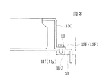
図3は本発明の他の実施の形態を示す側面図である。
図3に示す実施の形態では、シャーシ11の底板11Cから取付片11f1,11g1が突出しておらず、底板11Cの縁部よりも内側に取付穴11f,11gが穿設されている。そして、上記実施の形態と同様に補助シャーシ13の取付部13E,13Fは、シャーシ11の底板11Cの上に重ねられると、前記取付穴11fが取付穴13dに、取付穴11gが取付穴13eにそれぞれ重なり合い、これらがねじ18により共締め固定される。
【0023】
このように、補助シャーシ13から脚部13C,13Dを延ばし、その端部を折曲げ形成した取付部13E,13Fをシャーシ11の取付片11f1,11g1、または底板11Cに重ね合せ、この取付部13E,13Fと取付片11f1,11g1、または取付部13E,13Fと底板11Cとを筐体20の固定部21に共締めする構成としたことにより、固定部21に固定されるシャーシ11の強度を高くでき、開口部が形成されたシャーシ11および側板12全体の歪みを防止できるようになる。
【0024】
特に、シャーシ11に対しねじ締め固定部(11f,11g)を支点とした変形力が作用しても、ねじ締め固定部とシャーシ11の側板11Aおよび側板12Bとの双方にわたって補助シャーシ13が設けられているために、シャーシ11がねじ締め固定部を支点として歪むことがない。また、シャーシ11と筐体20との固定部と、補助シャーシ13と筐体20との固定部の、双方の固定機構を別々に設ける必要がなく、最少のねじ締め作業で、シャーシ11と補助シャーシ13を筐体20に固定することができる。
【0025】
また、図1と図2に示すように、シャーシ11に取付片11f1,11g1が形成されてこの取付片11f1,11g1に取付穴11f,11gが形成されている場合には、補助シャーシ13の取付部13E,13Fにより、この取付片11f1,11g1の変形を防止できる。
【0026】
なお、上記実施の形態においては、取付部13E,13Fをシャーシ11の底板11Cに重なるようにしたもので示したが、その他例えば側板11Aや後板11Bに重ね合せ、側板11Aや後板11Bと補助シャーシ13とを筐体20に共締めしてもよい。
また、取付部13E,13Fが共締めされる箇所は、底板11CのY1側端部に限られるものではなく、例えばY方向中央部分であってもよいし、Y2側の端部であってもよい。
また上記のように、補助シャーシ13はシャーシ11の一部を覆うカバー状のものに限られるものではなく、シャーシ11全体を覆うカバーであってもよい。
【0027】
【発明の効果】
以上詳述した本発明によれば、補助シャーシによってシャーシの強度を補強できるのみならず、シャーシの取付部を補強することができるため、筐体との取付部を支点としたシャーシの歪みを防止できる。
また、補助シャーシを補強部材として、シャーシの側板間をこの補助シャーシで連結させることにより、シャーシ全体の強度を高めることができる。
【図面の簡単な説明】
【図1】本発明における車載用機器の実施の形態として、MD(ミニディスク)プレーヤの機構部を示す分解斜視図、
【図2】図1の機構部をII方向から見た側面図、
【図3】本発明の他の実施の形態を示す機構部の部分側面図、
【図4】従来の車載用機器内のシャーシを概念的に示す斜視図、
【符号の説明】
11 シャーシ
11A 側板
11B 後板
11C 底板
11D 開口部
11f,11g 取付穴
11f1,11g1 取付片
12 側板
13 補助シャーシ
13C,13D 脚部
13E,13F 取付部
13d、13e 取付穴
18 ねじ(固定部材)
20 筐体
21 固定部
B 車載用機器(MDプレーヤ)の機構部
U 駆動ユニット
S1,S2,S3 弾性支持部材[0001]
BACKGROUND OF THE INVENTION
The present invention relates to a vehicle-mounted device in which a drive unit for a recording medium is incorporated in a chassis, and more particularly to a vehicle-mounted device that can increase the strength of the chassis without complicating the shape of the chassis.
[0002]
[Prior art]
FIG. 4 is a perspective view showing a chassis structure in a conventional in-vehicle device.
The in-vehicle device A shown in FIG. 4 is, for example, an MD (mini disc) player, and the
[0003]
Inside the
[0004]
[Problems to be solved by the invention]
However, the in-vehicle device having the
(1) As shown in FIG. 4, many openings are formed on each surface of the
(2) In order to solve the above problem, it is conceivable to provide a reinforcing member for reinforcing the
(3) In addition, in the case of having the
[0005]
The present invention is for solving the above-described conventional problems, and can enhance the strength of the chassis fixed in the casing, and the in-vehicle apparatus does not complicate the structure for mounting the chassis and the casing. The purpose is to provide.
[0006]
[Means for Solving the Problems]
The present invention includes a housing, before a chassis provided in Kikatami body, in-vehicle equipment that includes a driving unit housed in said chassis,
The chassis has a bottom plate and a pair of side plates spaced apart from each other, and the bottom plate has a mounting portion having a mounting hole ,
A top plate facing the bottom plate at a distance is integrally formed with the auxiliary chassis assembled to the chassis , and the top plate and both side plates are fixed at a position away from the bottom plate, and the auxiliary chassis is connected between the side plates. It functions as a reinforcing member that connects the
Wherein the mounting portion formed on the bottom plate are superposed mounting portions formed in the auxiliary chassis, two mounting portions, and is characterized in that the are in Flip sleep to the housing are fastened together.
[0007]
The in-vehicle device according to the present invention has a drive unit that drives, for example, an MD (mini disc), a CD (compact disc), a DVD (digital versatile disc) or the like incorporated in a housing.
In the present invention, the strength of the chassis can be increased by incorporating the auxiliary chassis into the chassis fixed to the housing side. In addition, since the mounting part of the auxiliary chassis overlaps the mounting part of the chassis and these mounting parts are fastened together and fixed, the auxiliary chassis also reinforces the chassis itself and the mounting part between the chassis and the chassis. For example, it is possible to solve the problem that the chassis is easily distorted with the mounting portion with the housing as a fulcrum.
[0008]
Therefore, the area occupied by the opening of the chassis can be increased, and when the drive unit vibrates in the chassis, the contact between the drive unit and the inner surface of the chassis can be prevented, and various parts are incorporated into the chassis through the opening. It becomes easy.
In order to exert the above-described effects, it is necessary not only to form the attachment portion to the housing in the auxiliary chassis, but also to fix the auxiliary chassis and the chassis at any location.
[0009]
In the above, for example, one of the side plates is integrally bent from the bottom plate, and the other side plate is provided separately from the one side plate and attached to the bottom plate.
If the chassis side plates are connected to each other by the auxiliary chassis, the auxiliary chassis can effectively prevent distortion of the chassis side plates. When the side plates are connected by the auxiliary chassis, the chassis can be reinforced even when a large opening is formed in the ceiling of the chassis.
[0010]
The drive unit is preferably supported in the chassis via an elastic support member.
In the case where the drive unit is elastically supported in the chassis, the occupation ratio of the opening of the chassis is increased so that the drive unit does not hit the inner surface of the chassis when the drive unit vibrates in the chassis. However, the auxiliary chassis can sufficiently reinforce the chassis having a high occupation rate of the opening.
[0011]
The present invention is effective when the mounting piece protrudes integrally from the chassis, the mounting hole is formed in the mounting piece, and the mounting portion of the auxiliary chassis overlaps the mounting piece.
In other words, if the mounting piece protrudes from the chassis by bending or the like, the strength of the mounting piece itself becomes very weak, but the mounting piece can be reinforced by the auxiliary chassis so that the mounting portion of the chassis relative to the chassis can be reinforced. Become.
[0012]
In addition, as shown in FIG. 1 and FIG. 2, the present invention has not only a mounting piece protruding from the chassis but also a mounting hole formed inside the side edge of the chassis as shown in FIG. It is also effective in things. Even if the part in which this mounting hole is formed is not a mounting piece but inside the side edge of the chassis, the chassis is attached to this part as a fulcrum by fixing the auxiliary chassis together with this part. As a result, distortion and other problems do not occur.
[0013]
DETAILED DESCRIPTION OF THE INVENTION
The present invention will be described below with reference to the drawings.
FIG. 1 is an exploded perspective view showing a mechanism portion of an MD (mini disc) player as an embodiment of an in-vehicle device according to the present invention, and FIG. 2 shows a state where the mechanism portion of FIG. It is the side view seen from.
The mechanism part B shown in FIG. 1 is provided in a
A drive unit U including a drive unit having an MD rotation drive mechanism, a recording / reproducing head, etc., and an MD insertion / ejection means (not shown) is housed inside the frame of the mechanism unit B. Yes.
[0014]
In the
[0015]
Further, elastic support members S1, S2, and S3 such as dampers and coil springs are provided inside the frame of the mechanism portion B, and the drive unit U indicated by a one-dot chain line in the drawing is elastic. It is supported by.
[0016]
A
[0017]
On the lower side of the
[0018]
The
[0019]
In this state, a large opening surrounded by the
[0020]
As described above, the
Further, attachment holes 11f and 11g are formed at both ends of the
[0021]
On the other hand, mounting
As shown in FIG. 2, a fixing
[0022]
FIG. 3 is a side view showing another embodiment of the present invention.
In the embodiment shown in FIG. 3, the mounting pieces 11f1 and 11g1 do not protrude from the
[0023]
In this manner, the
[0024]
In particular, even when a deformation force with the screw tightening fixing portion (11f, 11g) as a fulcrum acts on the
[0025]
As shown in FIGS. 1 and 2, when the mounting pieces 11f1 and 11g1 are formed in the
[0026]
In the above embodiment, the mounting
Further, the place where the
Further, as described above, the
[0027]
【The invention's effect】
According to the present invention described in detail above, not only can the strength of the chassis be reinforced by the auxiliary chassis, but also the mounting portion of the chassis can be reinforced, thereby preventing distortion of the chassis with the mounting portion as a fulcrum. it can.
Moreover, the strength of the entire chassis can be increased by connecting the chassis side plates with the auxiliary chassis using the auxiliary chassis as a reinforcing member.
[Brief description of the drawings]
FIG. 1 is an exploded perspective view showing a mechanism part of an MD (mini disc) player as an embodiment of a vehicle-mounted device according to the present invention;
FIG. 2 is a side view of the mechanism portion of FIG.
FIG. 3 is a partial side view of a mechanism portion showing another embodiment of the present invention.
FIG. 4 is a perspective view conceptually showing a chassis in a conventional vehicle-mounted device;
[Explanation of symbols]
11
20
Claims (4)
前記シャーシは、底板と、互いに間隔を空けて配された一対の側板とを有し、前記底板に、取付穴を有する取付部が形成されており、
前記シャーシに組み付けられる補助シャーシに、前記底板と距離を空けて対向する天板が一体に形成され、この天板と両側板とが、底板から離れた位置で固定されて、補助シャーシが側板どうしを連結する補強部材として機能しており、
底板に形成された前記取付部に前記補助シャーシに形成された取付部が重ねられて、両取付部が、前記筐体にねじで共締め固定されていることを特徴とする車載用機器。A housing, before a chassis provided in Kikatami body, in-vehicle equipment that includes a driving unit housed in said chassis,
The chassis has a bottom plate and a pair of side plates spaced from each other, and the bottom plate has a mounting portion having a mounting hole ,
A top plate facing the bottom plate at a distance is integrally formed on the auxiliary chassis assembled to the chassis , and the top plate and both side plates are fixed at a position away from the bottom plate, and the auxiliary chassis is connected between the side plates. It functions as a reinforcing member that connects
Vehicle equipment which said superimposed mounting portion formed in the auxiliary chassis to the attachment portion formed in the bottom plate, two mounting portions, characterized in that it is fastened together with Flip sleep to the housing.
Priority Applications (1)
| Application Number | Priority Date | Filing Date | Title |
|---|---|---|---|
| JP20619698A JP3763976B2 (en) | 1998-07-22 | 1998-07-22 | Automotive equipment |
Applications Claiming Priority (1)
| Application Number | Priority Date | Filing Date | Title |
|---|---|---|---|
| JP20619698A JP3763976B2 (en) | 1998-07-22 | 1998-07-22 | Automotive equipment |
Publications (2)
| Publication Number | Publication Date |
|---|---|
| JP2000038091A JP2000038091A (en) | 2000-02-08 |
| JP3763976B2 true JP3763976B2 (en) | 2006-04-05 |
Family
ID=16519395
Family Applications (1)
| Application Number | Title | Priority Date | Filing Date |
|---|---|---|---|
| JP20619698A Expired - Fee Related JP3763976B2 (en) | 1998-07-22 | 1998-07-22 | Automotive equipment |
Country Status (1)
| Country | Link |
|---|---|
| JP (1) | JP3763976B2 (en) |
-
1998
- 1998-07-22 JP JP20619698A patent/JP3763976B2/en not_active Expired - Fee Related
Also Published As
| Publication number | Publication date |
|---|---|
| JP2000038091A (en) | 2000-02-08 |
Similar Documents
| Publication | Publication Date | Title |
|---|---|---|
| JP3569617B2 (en) | Switch mounting structure for vehicle | |
| JP3621349B2 (en) | Corner reinforcement device for disk unit chassis | |
| JP3763976B2 (en) | Automotive equipment | |
| JPS6316698A (en) | Cubicle for electronic equipment | |
| JP4337117B2 (en) | Front panel drive | |
| KR100242773B1 (en) | A coupling structure of front panel for a car audio | |
| JPH08255471A (en) | Holding unit | |
| JP3105145B2 (en) | Car | |
| JP2529837Y2 (en) | Rotating part structure of retractable door mirror | |
| JP2576373Y2 (en) | Equipment body support mechanism for in-vehicle equipment | |
| JP3403587B2 (en) | Housing structure of in-vehicle equipment | |
| JP3210162B2 (en) | Door handle device for automobile | |
| JPH115467A (en) | Seat slide device | |
| JP2917669B2 (en) | Assembly structure for parts in the instrument panel of a car | |
| JP3150053B2 (en) | Anti-rattle structure of slide knob | |
| JP2002178766A (en) | Flexible blind attachment structure for vehicle sun roof | |
| JPH10147185A (en) | On-vehicle monitor device | |
| JP3946417B2 (en) | Automotive electronics | |
| JP2584091Y2 (en) | Steering wheel with airbag device | |
| JP3191584B2 (en) | Automotive console box | |
| JP3339232B2 (en) | Automotive rear parcel trim | |
| JP3907420B2 (en) | Seesaw Mami and audio equipment | |
| JP2592826Y2 (en) | Steering wheel with airbag device | |
| JP2697446B2 (en) | Radiator support structure | |
| JPS6032301Y2 (en) | Especially the mounting structure of the dust cover opening/closing device of players etc. |
Legal Events
| Date | Code | Title | Description |
|---|---|---|---|
| A131 | Notification of reasons for refusal |
Free format text: JAPANESE INTERMEDIATE CODE: A131 Effective date: 20050308 |
|
| A521 | Written amendment |
Free format text: JAPANESE INTERMEDIATE CODE: A523 Effective date: 20050428 |
|
| TRDD | Decision of grant or rejection written | ||
| A01 | Written decision to grant a patent or to grant a registration (utility model) |
Free format text: JAPANESE INTERMEDIATE CODE: A01 Effective date: 20060117 |
|
| A61 | First payment of annual fees (during grant procedure) |
Free format text: JAPANESE INTERMEDIATE CODE: A61 Effective date: 20060118 |
|
| R150 | Certificate of patent or registration of utility model |
Free format text: JAPANESE INTERMEDIATE CODE: R150 |
|
| FPAY | Renewal fee payment (event date is renewal date of database) |
Free format text: PAYMENT UNTIL: 20100127 Year of fee payment: 4 |
|
| FPAY | Renewal fee payment (event date is renewal date of database) |
Free format text: PAYMENT UNTIL: 20100127 Year of fee payment: 4 |
|
| FPAY | Renewal fee payment (event date is renewal date of database) |
Free format text: PAYMENT UNTIL: 20110127 Year of fee payment: 5 |
|
| FPAY | Renewal fee payment (event date is renewal date of database) |
Free format text: PAYMENT UNTIL: 20110127 Year of fee payment: 5 |
|
| FPAY | Renewal fee payment (event date is renewal date of database) |
Free format text: PAYMENT UNTIL: 20120127 Year of fee payment: 6 |
|
| FPAY | Renewal fee payment (event date is renewal date of database) |
Free format text: PAYMENT UNTIL: 20120127 Year of fee payment: 6 |
|
| FPAY | Renewal fee payment (event date is renewal date of database) |
Free format text: PAYMENT UNTIL: 20130127 Year of fee payment: 7 |
|
| FPAY | Renewal fee payment (event date is renewal date of database) |
Free format text: PAYMENT UNTIL: 20130127 Year of fee payment: 7 |
|
| FPAY | Renewal fee payment (event date is renewal date of database) |
Free format text: PAYMENT UNTIL: 20140127 Year of fee payment: 8 |
|
| LAPS | Cancellation because of no payment of annual fees |