JP3763774B2 - Quenched alloy for iron-based rare earth alloy magnet and method for producing iron-based rare earth alloy magnet - Google Patents
Quenched alloy for iron-based rare earth alloy magnet and method for producing iron-based rare earth alloy magnet Download PDFInfo
- Publication number
- JP3763774B2 JP3763774B2 JP2001358767A JP2001358767A JP3763774B2 JP 3763774 B2 JP3763774 B2 JP 3763774B2 JP 2001358767 A JP2001358767 A JP 2001358767A JP 2001358767 A JP2001358767 A JP 2001358767A JP 3763774 B2 JP3763774 B2 JP 3763774B2
- Authority
- JP
- Japan
- Prior art keywords
- phase
- alloy
- atomic
- rare earth
- magnet
- Prior art date
- Legal status (The legal status is an assumption and is not a legal conclusion. Google has not performed a legal analysis and makes no representation as to the accuracy of the status listed.)
- Expired - Fee Related
Links
Images


Classifications
-
- B—PERFORMING OPERATIONS; TRANSPORTING
- B82—NANOTECHNOLOGY
- B82Y—SPECIFIC USES OR APPLICATIONS OF NANOSTRUCTURES; MEASUREMENT OR ANALYSIS OF NANOSTRUCTURES; MANUFACTURE OR TREATMENT OF NANOSTRUCTURES
- B82Y25/00—Nanomagnetism, e.g. magnetoimpedance, anisotropic magnetoresistance, giant magnetoresistance or tunneling magnetoresistance
-
- H—ELECTRICITY
- H01—ELECTRIC ELEMENTS
- H01F—MAGNETS; INDUCTANCES; TRANSFORMERS; SELECTION OF MATERIALS FOR THEIR MAGNETIC PROPERTIES
- H01F1/00—Magnets or magnetic bodies characterised by the magnetic materials therefor; Selection of materials for their magnetic properties
- H01F1/01—Magnets or magnetic bodies characterised by the magnetic materials therefor; Selection of materials for their magnetic properties of inorganic materials
- H01F1/03—Magnets or magnetic bodies characterised by the magnetic materials therefor; Selection of materials for their magnetic properties of inorganic materials characterised by their coercivity
- H01F1/032—Magnets or magnetic bodies characterised by the magnetic materials therefor; Selection of materials for their magnetic properties of inorganic materials characterised by their coercivity of hard-magnetic materials
- H01F1/04—Magnets or magnetic bodies characterised by the magnetic materials therefor; Selection of materials for their magnetic properties of inorganic materials characterised by their coercivity of hard-magnetic materials metals or alloys
- H01F1/047—Alloys characterised by their composition
- H01F1/053—Alloys characterised by their composition containing rare earth metals
- H01F1/055—Alloys characterised by their composition containing rare earth metals and magnetic transition metals, e.g. SmCo5
- H01F1/057—Alloys characterised by their composition containing rare earth metals and magnetic transition metals, e.g. SmCo5 and IIIa elements, e.g. Nd2Fe14B
- H01F1/0579—Alloys characterised by their composition containing rare earth metals and magnetic transition metals, e.g. SmCo5 and IIIa elements, e.g. Nd2Fe14B with exchange spin coupling between hard and soft nanophases, e.g. nanocomposite spring magnets
Description
【0001】
【発明の属する技術分野】
本発明は、各種モータやアクチュエータに好適に使用される永久磁石の製造方法に関し、特に複数の強磁性相を有する鉄基希土類合金磁石の製造方法に関している。
【0002】
【従来の技術】
近年、家電用機器、OA機器、および電装品等において、より一層の高性能化と小型軽量化が要求されている。そのため、これらの機器に使用される永久磁石については、磁気回路全体としての性能対重量比を最大にすることが求められており、例えば残留磁束密度Brが0.5T(テスラ)以上の永久磁石を用いることが要求されている。しかし、従来の比較的安価なハードフェライト磁石によっては、残留磁束密度Brを0.5T以上にすることはできない。
【0003】
現在、0.5T以上の高い残留磁束密度Brを有する永久磁石としては、粉末冶金法によって作製されるSm−Co系磁石が知られている。Sm−Co系磁石以外では、粉末冶金法によって作製されるNd−Fe−B系磁石や、液体急冷法によって作製されるNd−Fe−B系急冷磁石が高い残留磁束密度Brを発揮することができる。前者のNd−Fe−B系磁石は、例えば特開昭59−46008号公報に開示されており、後者のNd−Fe−B系急冷磁石は例えば特開昭60−9852号公報に開示されている。
【0004】
【発明が解決しようとする課題】
しかしながら、Sm−Co系磁石は、原料となるSmおよびCoのいずれもが高価であるため、磁石価格が高いという欠点を有している。
【0005】
Nd−Fe−B系磁石の場合は、安価なFeを主成分として(全体の60重量%〜70重量%程度)含むため、Sm−Co系磁石に比べて安価ではあるが、その製造工程に要する費用が高いという問題がある。製造工程費用が高い理由のひとつは、含有量が全体の10原子%〜15原子%程度を占めるNdの分離精製や還元反応に大規模な設備と多大な工程が必要になることである。また、粉末冶金法による場合は、どうしても製造工程数が多くなる。
【0006】
これに対し、液体急冷法によって製造されるNd−Fe−B系急冷磁石は、溶解工程→液体冷却工程→熱処理工程といった比較的簡単な工程で得られるため、粉末冶金法によるNd−Fe−B系磁石に比べて工程費用が安いという利点がある。しかし、液体急冷法による場合、バルク状の永久磁石を得るには、急冷合金から作製した磁石粉末を樹脂と混ぜ、ボンド磁石を形成する必要があるので、成形されたボンド磁石に占める磁石粉末の充填率(体積比率)は高々80%程度である。また、液体急冷法によって作製した急冷合金は、磁気的に等方性である。
【0007】
以上の理由から、液体急冷法を用いて製造したNd−Fe−B系急冷磁石は、粉末冶金法によって製造した異方性のNd−Fe−B系焼結磁石に比べてBrが低いという問題を有している。
【0008】
Nd−Fe−B系急冷磁石の特性を改善する手法としては、特開平1−7502号公報に記載されているように、Zr、Nb、Mo、Hf、Ta、およびWからなる群から選択された少なくとも一種の元素と、Ti、V、およびCrからなる群から選択された少なくとも一種の元素とを複合的に添加することが有効である。このような元素の添加によって、保磁力HcJと耐食性とが向上するが、残留磁束密度Brを改善する有効な方法は、ボンド磁石の密度を向上すること以外に知られていない。
【0009】
Nd−Fe−B系磁石の場合、希土類元素の濃度が比較的に低い組成、すなわち、Nd3.8Fe77.2B19(原子%)の近傍組成を持ち、Fe3B型化合物を主相とする磁石材料が提案されている(R. Coehoorn等、J. de Phys, C8,1998, 669〜670頁)。この永久磁石材料は、液体急冷法によって作製したアモルファス合金に対して結晶化熱処理を施すことにより、軟磁性であるFe3B相および硬磁性であるNd2Fe14B相が混在する微細結晶集合体から形成された準安定構造を有しており、「ナノコンポジット磁石」と称されている。このようなナノコンポジット磁石については、1T以上の高い残留磁束密度Brを有することが報告されているが、その保磁力HcJは160kA/m〜240kA/mと比較的低い。そのため、この永久磁石材料の使用は、磁石の動作点が1以上になる用途に限られている。
【0010】
また、ナノコンポジット磁石の原料合金に種々の金属元素を添加し、磁気特性を向上させる試みがなされているが(特開平3-261104号公報、米国特許4,836,868号、特開平7−122412号公報、国際出願の国際公開公報WO003/03403、W.C.Chan, et.al. "THE EFFECTS OF REFRACTORY METALS ON THE MAGNETIC PROPERTIES OF α-Fe/R2Fe14B-TYPE NANOCOMPOSITES", IEEE, Trans. Magn. No. 5, INTERMAG. 99, Kyongiu, Korea pp.3265-3267, 1999)、必ずしも充分な「コスト当りの特性値」は得られていない。
【0011】
本発明は、上記事情に鑑みてなされたものであり、その目的とするところは、高い保磁力(例えばHcJ≧480kA/m)を維持しながら、残留磁束密度Br≧0.85Tを満足する優れた磁気特性を持つ鉄基合金磁石を安価に製造し得る永久磁石の製造方法を提供することにある。
【0012】
【課題を解決するための手段】
本発明による鉄基希土類合金磁石は、組成式が(Fe1-mTm)100-x-y-zQxRyMz(TはCoおよびNiからなる群から選択された1種以上の元素、QはBおよびCからなる群から選択された1種以上の元素、RはLaおよびCeを実質的に含まない1種以上の希土類金属元素、MはTi、Zr、およびHfからなる群から選択された金属元素であって、Tiを必ず含む少なくとも1種の金属元素)で表現され、組成比率x、y、zおよびmが、それぞれ、10<x≦20原子%、6≦y<10原子%、0.1≦z≦12原子%、および0≦m≦0.5を満足し、2種類以上の強磁性結晶相を含有し、硬磁性相の平均サイズが10nm以上200nm以下、軟磁性相の平均サイズが1nm以上100nm以下の範囲内にある。
【0013】
ある好ましい実施形態において、組成比率x、y、zおよびmは、それぞれ、10<x<17at%、8≦y≦9.3at%、0.5≦z≦6at%を満足する。
【0014】
ある好ましい実施形態においては、R2Fe14B型化合物相、硼化物相、およびα−Fe相が同一の金属組織内に混在している。
【0015】
ある好ましい実施形態において、前記α−Fe相および硼化物相の平均結晶粒径は1nm以上50nm以下である。
【0016】
ある好ましい実施形態において、前記硼化物相は、強磁性の鉄基硼化物を含んでいる。
【0017】
ある好ましい実施形態において、前記鉄基硼化物は、Fe3Bおよび/またはFe23B6を含んでいる。
【0018】
ある好ましい実施形態においては、組成比率xおよびzが、z/x≧0.1を満足する。
【0019】
ある好ましい実施形態においては、前記Rの組成比率yが9.5原子%以下である。
【0020】
ある好ましい実施形態においては、前記Rの組成比率yが9.0原子%以下である。
【0021】
ある好ましい実施形態においては、厚さが10μm以上300μm以下の薄帯形状を有している。
【0022】
前記鉄基希土類合金磁石は粉末化されていてもよい。この場合、粉末粒子の平均粒径は30μm以上250μm以下であることが好ましい。
【0023】
ある好ましい実施形態においては、保磁力HcJ≧480kA/m、残留磁束密度Br≧0.7Tの硬磁気特性を有する磁石が得られる。
【0024】
更に好ましい実施形態では、残留磁束密度Br≧0.85T、最大エネルギ積(BH)max≧120kJ/m3、固有保磁力HcJ≧480kA/mの硬磁気特性を有している磁石が得られる。
【0025】
本発明によるボンド磁石は、上記鉄基希土類合金磁石の粉末を含む磁石粉末を樹脂で成形したものである。
【0026】
本発明による鉄基希土類合金磁石用急冷合金は、組成式が(Fe1-mTm)100-x-y-zQxRyMz(TはCoおよびNiからなる群から選択された1種以上の元素、QはBおよびCからなる群から選択された1種以上の元素、RはLaおよびCeを実質的に含まない1種以上の希土類金属元素、MはTi、Zr、およびHfからなる群から選択された金属元素であって、Tiを必ず含む少なくとも1種の金属元素)で表現され、組成比率x、y、zおよびmが、それぞれ、10<x≦20原子%、6≦y<10原子%、0.1≦z≦12原子%、および0≦m≦0.5を満足する。
【0027】
ある好ましい実施形態では、α−Feを実質的に含まず、R2Fe14B型化合物相及びアモルファス相を含む組織を有し、前記R2Fe14B型化合物相が体積比率で全体の60%以上を占めている。
【0028】
ある好ましい実施形態では、10<x<17at%、8≦y≦9.3at%、および0.5≦z≦6at%を満足し、平均粒径50nm以下のR2Fe14B型化合物相が60体積%以上含まれる。
【0029】
本発明による鉄基希土類合金磁石用急冷合金は、Fe、Q(QはBおよびCからなる群から選択された1種以上の元素)、R(Rは希土類元素)、およびTiを含有する合金溶湯を冷却することによって作製され、アモルファス相を含み、熱処理によってα−Fe結晶相の成長開始より先にR2Fe14B型結晶構造を持つ化合物結晶相の成長を開始する組織を有している。
【0030】
本発明による鉄基希土類合金磁石の製造方法は、Fe、Q(QはBおよびCからなる群から選択された1種以上の元素)、R(Rは希土類元素)、およびTiを含有する合金溶湯を作製する工程と、前記合金溶湯を冷却し、アモルファス相を含む凝固合金を作製する工程と、前記凝固合金を加熱することによって、R2Fe14B型結晶構造を持つ化合物結晶相の成長を開始させ、その後にα−Fe結晶相の成長を開始させる工程とを包含する。
【0031】
ある好ましい実施形態では、ストリップキャスト法を用いて前記合金溶湯を冷却する。
【0032】
本発明による鉄基希土類合金磁石の製造方法は、組成式が(Fe1-mTm)100-x-y-zQxRyMz(TはCoおよびNiからなる群から選択された1種以上の元素、QはBおよびCからなる群から選択された1種以上の元素、RはLaおよびCeを実質的に含まない1種以上の希土類金属元素、MはTi、Zr、およびHfからなる群から選択された金属元素であって、Tiを必ず含む少なくとも1種の金属元素)で表現され、組成比率x、y、zおよびmが、それぞれ、10<x≦20原子%、6≦y<10原子%、0.1≦z≦12原子%、および0≦m≦0.5を満足する合金の溶湯を作製する工程と、前記合金の溶湯を急冷することによって、R2Fe14B型結晶相とアモルファス相とが混在する急冷合金を作製する冷却工程と、前記急冷合金を結晶化し、それによって2種類以上の強磁性結晶相を含有し、硬磁性相の平均サイズが10nm以上200nm以下、軟磁性相の平均サイズが1nm以上100nm以下の範囲内にある組織を形成する工程とを包含する。
【0033】
ある好ましい実施形態では、前記冷却工程において、体積比率で60%以上のR2Fe14B型化合物相を含む急冷合金を作製する。
【0034】
ある好ましい実施形態において、前記冷却工程は、圧力30kPa以上の雰囲気ガス中で前記合金の溶湯を急冷し、平均粒径50nm以下のR2Fe14B型化合物相を含む急冷合金を作製することを含む。
【0035】
ある好ましい実施形態において、前記冷却工程は、前記合金溶湯を回転する冷却ロールの表面に接触させ、過冷却液体状態にある合金を形成する工程と、前記過冷却状態にある合金が冷却ロールから離れた後、前記雰囲気ガスによって前記過冷却状態にある合金から熱を奪い、前記R2Fe14B型化合物相の成長を行なう工程とを包含する。
【0036】
ある好ましい実施形態では、前記急冷合金に対して結晶化熱処理を行ない、少なくともR2Fe14B型化合物相、α−Fe相、および硼化物相を含む3種類以上の結晶相を含有する組織を形成し、前記R2Fe14B型化合物相の平均結晶粒径を20nm以上150nm以下、前記α−Fe相および硼化物相の平均結晶粒径を1nm以上50nm以下とする工程を包含する。
【0037】
ある好ましい実施形態において、前記硼化物相は、強磁性の鉄基硼化物を含んでいる。
【0038】
ある好ましい実施形態において、前記鉄基硼化物は、Fe3Bおよび/またはFe23B6を含んでいる。
【0039】
ある好ましい実施形態では、ストリップキャスト法を用いて前記合金の溶湯を冷却する。
【0040】
本発明によるボンド磁石の製造方法は、上記いずれかの鉄基希土類合金磁石の製造方法によって作製された鉄基希土類合金磁石の粉末を用意する工程と、前記鉄基希土類合金磁石の粉末を用いてボンド磁石を作製する工程とを包含する。
【0041】
ある好ましい実施形態では、粉末の表面に表面処理が施されている。
【0042】
ある好ましい実施形態では、ボンド磁石に対して表面処理が施されている。
【0043】
【発明の実施の形態】
本発明の鉄基希土類合金磁石は、Tiを含有する希土類−鉄−硼素系合金の溶湯を冷却し、それによって凝固した急冷合金から形成されている。この急冷凝固合金は、結晶相を含むものであるが、必要に応じて加熱され、更に結晶化が進められる。
【0044】
本発明者は、特定範囲の組成を有する鉄基希土類合金へTiを添加することにより、合金溶湯の冷却過程で生じやすいα−Fe相の析出・成長を抑制し、硬磁気特性を担うR2Fe14B型化合物相の結晶成長を優先的かつ均一に進行させることができることを見出し、本発明を想到するに至った。
【0045】
Tiを添加しなかった場合、Nd2Fe14B相の析出・成長に先だってα−Fe相が析出し、成長しやすい。そのため、急冷合金に対する結晶熱処理が完了した段階では、軟磁性のα−Fe相が粗大化してしまう。
【0046】
これに対し、Tiを添加した場合は、α−Fe相の析出・成長のキネティクス(kinetics)が遅くなり、析出・成長に時間を要するため、α−Fe相の析出・成長が完了する前にNd2Fe14B相の析出・成長が開始すると考えられる。このため、α−Fe相が粗大化する前にNd2Fe14B相が均一に分散した状態に大きく成長する。また、TiはBに対する親和性が強く、鉄基硼化物の中に濃縮されやすいようである。鉄基硼化物内でTiとBが強く結合することにより、Ti添加は鉄基硼化物を安定化すると考えられる。
【0047】
本発明によれば、Tiの働きによって鉄基硼化物やα−Fe相などの軟磁性相が微細化されるともに、Nd2Fe14B相が均一に分散し、しかもNd2Fe14B相の体積比率が増加する。その結果、保磁力および磁化(残留磁束密度)が増加し、減磁曲線の角形性が向上する。
【0048】
以下、本発明の鉄基希土類合金磁石をより詳細に説明する。
【0049】
本発明の鉄基希土類合金磁石は、好適には、その組成式が(Fe1-mTm)100-x-y-zQxRyMzで表現される。ここで、TはCoおよびNiからなる群から選択された1種以上の元素、QはB(硼素)およびC(炭素)からなる群から選択された1種以上の元素、RはLaおよびCeを実質的に含まない1種以上の希土類金属元素、MはTi、Zr、およびHfからなる群から選択された少なくとも1種の金属元素であり、Tiを必ず含んでいる。
【0050】
組成比率を規定するx、y、z、およびmは、それぞれ、10<x≦20原子%、6≦y<10原子%、0.1≦z≦12原子%、および0≦m≦0.5の関係を満足することが好ましい。
【0051】
本発明の鉄基希土類合金磁石は、希土類元素の組成比率が全体の10原子%未満であるにもかかわらず、Tiの添加によって磁化(残留磁束密度)がTiを添加しない場合と同等のレベルを維持するか、または増加し、減磁曲線の角形性が向上するという予想外の効果が発揮される。
【0052】
本発明の鉄基希土類合金磁石では、軟磁性相のサイズが微細であるため、各構成相が交換相互作用によって結合し、硬磁性のR2Fe14B型化合物相以外に鉄基硼化物やα−Feのような軟磁性相が存在していても、合金全体としては優れた減磁曲線の角形性を示すことが可能になる。
【0053】
本発明の鉄基希土類合金磁石は、好適には、R2Fe14B型化合物相の飽和磁化と同等、または、それよりも高い飽和磁化を有する鉄基硼化物やα−Feを含有している。この鉄基硼化物は、例えば、Fe3B(飽和磁化1.5T)やFe23B6(飽和磁化1.6T)である。ここで、R2Fe14Bの飽和磁化は約1.6Tであり、α−Feの飽和磁化は2.1Tである。
【0054】
通常、Bの組成比率xが10原子%を超え、しかも希土類元素Rの組成比率yが6原子%以上8原子%以下の範囲にある場合、R2Fe23B3が生成されるが、このような組成範囲にある原料合金を用いる場合であっても、本発明のようにTiを添加することにより、R2Fe23B3の代わりに、R2Fe14B、および、Fe23B6やFe3Bなどの鉄基硼化物を生成することができる。これらの鉄基硼化物は磁化向上に寄与する。
【0055】
本発明者の実験によると、Tiを添加した場合だけ、V、Cr、Mn、Nb、Moなどの他の種類の金属を添加した場合と異なり、磁化の低下が生じず、むしろ磁化が向上することが初めてわかった。また、Tiを添加した場合には、前述の他の添加元素と比べ、減磁曲線の角形性が特に良好なものとなった。
【0056】
また、このようなTi添加効果は、B濃度が10at%を超える場合に顕著に発揮される。以下、図1を参照しながら、この点を説明する。
【0057】
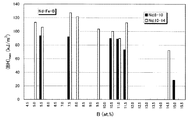
図1は、Tiが添加されていないNd−Fe−B磁石の最大磁気エネルギ積(BH)maxと硼素濃度との関係を示すグラフである。グラフ中、白いバーは10〜14at%のNdを含有する試料のデータを示し、黒いバーは8〜10at%のNdを含有する試料のデータを示している。これに対し、図2は、Tiが添加されたNd−Fe−B磁石の最大磁気エネルギ積(BH)maxと硼素濃度との関係を示すグラフである。グラフ中、白いバーは10〜14at%のNdを含有する試料のデータを示し、黒いバーは8〜10at%のNdを含有する試料のデータを示している。
【0058】
図1からわかるように、Tiが添加されていない試料では、Ndの含有量にかかわらず、硼素が10at%を超えて多くなるにつれ、最大磁気エネルギ積(BH)maxが低下している。この低下の程度は、Ndの含有量が10〜14at%の場合により大きい。このような傾向は従来から知られており、Nd2Fe14B相を主相とする永久磁石においては、硼素の量を10at%以下に設定することが好ましいと考えられてきた。例えば、米国特許4,836,868号は、硼素濃度は5〜9.5at%の実施例を開示し、更に、硼素濃度の好ましい範囲として4at%以上12at%未満、より好ましい範囲として4at%以上10at%以下の範囲を教示している。
【0059】
これに対して、Tiが添加された試料では、図2からわかるように、硼素が10at%を超える或る範囲で最大磁気エネルギ積(BH)maxが向上している。この向上はNdの含有量が8〜10at%の場合に特に顕著である。
【0060】
このように本発明によれば、B濃度が10at%を超えると磁気特性が劣化するという従来の技術常識からは予期できない効果をTi添加によって得ることが可能になる。
【0061】
次に、本発明による鉄基希土類合金磁石の製造方法を説明する。
【0062】
本発明の製造方法によれば、前記の組成を有する鉄基合金の溶湯を不活性雰囲気中で冷却し、それによってR2Fe14B型化合物相を全体の60体積%以上含む急冷合金を作製する。急冷合金中のR2Fe14B型化合物相の平均サイズは例えば80nm以下である。この急冷合金に対して、必要に応じて熱処理を行なえば、急冷合金中に残存していた非晶質を結晶化させることができる。
【0063】
好ましい実施形態では、上記合金溶湯を圧力30kPa以上の雰囲気中で冷却する。それにより、合金溶湯は、冷却ロールとの接触によって急冷されるだけでなく、冷却ロールから離れた後も、雰囲気ガスによる二次冷却効果を受けて適切に冷却される。
【0064】
冷却ロールの回転周速度を適切に調節することにより、冷却ロールから離れる際の合金の状態を過冷却液体状態に制御することが可能であり、過冷却状態の合金は、冷却ロールから離れた後、雰囲気ガスによって抜熱され、結晶化される。
【0065】
図3を参照しながら、大気雰囲気ガスによる二次冷却効果を説明する。図3は、冷却過程開始からの経過時間(Time)と合金温度(Temperature)との関係を模式的に示すグラフである。グラフには、雰囲気ガス圧力が30kPaを超える相対的に高い場合における合金の冷却経路aと、雰囲気ガス圧力が30kPaを下回る相対的に低い場合における合金の冷却経路bとが示されており、併せて、α−Fe相、Nd2Fe14B相、およびFe23B6相の析出領域が図示されている。ここでTmは合金の融点であり、Tgは合金のガラス転移温度である。
【0066】
図3からわかるように、雰囲気ガスの圧力が低い場合(冷却経路b)、雰囲気ガスによる大きな二次冷却効果を期待できないため、冷却ロールの回転速度を高くし、冷却ロールによる急冷(一次冷却)の速度を相対的に高くしている。合金は冷却ロールの表面から離れた後、雰囲気ガスによって相対的に遅い速度で冷却される(二次冷却)。冷却経路bの折れ曲がっているポイントが冷却ロールから合金の剥離した時点に相当している。
【0067】
一方、雰囲気ガスの圧力が相対的に高い場合(冷却経路a)、雰囲気ガスによる冷却(二次冷却)効果が強まり、Nd2Fe14B相が生成される領域を通過する時間が短縮される。このために、Nd2Fe14B相の成長が抑制され、微細なNd2Fe14B相が得られるものと推定される。
【0068】
このように、30kPaを下回るように雰囲気ガス圧力を低くすると、急冷合金中に生成されるR2Fe14B型化合物相の結晶粒径が粗大化するため、最終的に得られる磁石特性が劣化してしまうことになる。
【0069】
逆に、雰囲気ガスの圧力が常圧(大気圧)を超えて高くなり過ぎると、合金溶湯と冷却ロールとの間にまき込まれる雰囲気ガスの影響が大きくなり、冷却ロールによる充分な冷却が達成されなくなる。その結果、粗大なα−Feが析出し、良好な硬磁気特性が得られなくなる。
【0070】
本発明者の実験によれば、急冷時に雰囲気ガスの圧力は、30kPa以上でしかも常圧(101.3kPa)以下に制御することが好ましく、30kPa以上90kPa以下の範囲にすることが更に好ましい。より好ましい範囲は40kPa以上60kPa以下である。
【0071】
上記雰囲気ガス圧力のもとで、ロール表面周速度の好ましい範囲は4メートル/秒(m/秒)以上50m/秒以下である。ロール表面周速度が4m/秒より遅くなると、急冷合金中に含まれるR2Fe14B型化合物相の結晶粒が粗大化してしまうことになる。その結果、熱処理によってR2Fe14B型化合物相は更に大きくなり、磁気特性が劣化する可能性がある。
【0072】
一方、ロール表面周速度が50m/秒より速くなると、急冷合金がほぼ完全な非晶質となり、R2Fe14B型化合物相がほとんど析出しない状態になる。そのため、結晶化熱処理ではR2Fe14B型化合物相の粒成長が著しく、組織が不均一化してしまうため、磁気特性の向上が達成されない。
【0073】
実験によると、ロール表面周速度の更に好ましい範囲は5m/秒以上30m/秒以下であり、更に好ましい範囲は5m/秒以上20m/秒以下である。
【0074】
なお、本発明では、急冷合金中に粗大なα−Feをほとんど析出させず、微細なR2Fe14B型化合物相を有する組織、あるいは、微細なR2Fe14B型化合物相を有する組織とアモルファス相が混在した組織が作製される。これにより、熱処理後に鉄基硼化物相などの軟磁性相が硬磁性相の間(粒界)に微細に分散した状態または薄く広がった状態で存在する高性能の複合型永久磁石を得ることができる。なお、本明細書における「アモルファス相」とは、原子配列が完全に無秩序化した部分によってのみ構成される相だけではなく、結晶化の前駆体や微結晶(サイズ:数nm以下)、または原子クラスタを部分的に含んでいる相をも含むものとする。具体的には、X線回折や透過電子顕微鏡観察によって結晶構造を明確に同定できない相を広く「アモルファス相」と称することにする。
【0075】
従来、本発明が対象とするような組成に類似する組成を有する合金溶湯を冷却してR2Fe14B型化合物相を60体積%以上含むような急冷合金を作製しようとすると、α−Feが多く析出した合金組織が得られるため、その後の結晶化熱処理でα−Feが粗大化してしまうという問題があった。α−Feなどの軟磁性相が粗大化すると、磁石特性が大きく劣化し、到底実用に耐える永久磁石は得られない。
【0076】
特に本発明で用いる原料合金組成のように硼素の含有量が比較的多い場合、硼素が持つ高いアモルファス生成能のため、合金溶湯の冷却速度を遅くしても、結晶相は生成されにくかった。そのため、従来技術によれば、合金溶湯の冷却速度を充分に低下させてR2Fe14B型化合物相の体積比率が60%を超えるような急冷凝固合金を作製しようとすると、R2Fe14B型化合物相以外にα−Feまたはその前駆体が多く析出してしまい、その後の結晶化熱処理により、α−Fe相の粗大化が進行し、磁石特性が大きく劣化してしまった。
【0077】
以上のことから、従来、ナノコンポジット磁石の保磁力を増大させるには、合金溶湯の冷却速度を高め、急冷凝固合金の大部分がアモルファス相によって占められるような状態にした後、そのアモルファス相から結晶化熱処理により均一に微細化された組織を形成することが好ましいとの常識が存在していた。これは、微細な結晶相が分散した合金組織を持つナノコンポジットを得るには、制御しやすい熱処理工程でアモルファス相から結晶化を行なうべきと考えられていたからである。
【0078】
このため、アモルファス生成能に優れたLaを原料合金に添加し、その原料合金の溶湯を急冷することによってアモルファス相を主相とする急冷凝固合金を作製した後、結晶化熱処理でNd2Fe14B相およびα−Fe相の両方を析出・成長させ、いずれの相も数十nm程度の微細なものとする技術が報告されている(W.C.Chan, et.al. "THE EFFECTS OF REFRACTORY METALS ON THE MAGNETIC PROPERTIES OF α-Fe/R2Fe14B-TYPE NANOCOMPOSITES", IEEE, Trans. Magn. No. 5, INTERMAG. 99, Kyongiu, Korea pp.3265-3267, 1999)。なお、この論文は、Tiなどの高融点金属元素の微量添加(2at%)が磁石特性を向上させることと、希土類元素であるNdの組成比率を9.5at%よりも11.0at%に増加させることがNd2Fe14B相およびα−Fe相の両方を微細化する上で好ましいことを教示している。上記高融点金属の添加は、硼化物(R2Fe23B3やFe3B)の生成を抑制し、Nd2Fe14B相およびα−Fe相の2相のみからなる磁石を作製するために行なわれている。
【0079】
これに対し、本発明では、添加Tiの働きにより、急冷凝固工程でα−Fe相の析出を抑え、更には、結晶化熱処理工程における鉄基硼化物やα−Fe相などの軟磁性相の粗大化を抑制することができる。
【0080】
本発明によれば、希土類元素量が比較的少ない(9.3at%以下)原料合金を用いながら、磁化(残留磁束密度)および保磁力が高く、減磁曲線の角形性にも優れた永久磁石を製造することができる。
【0081】
前述のように、本発明による磁石の保磁力増加は、Nd2Fe14B相を冷却工程で優先的に析出・成長させ、それによってNd2Fe14B相の体積比率を増加させながら、しかし軟磁性相の粗大化を抑制したことによって実現する。また、磁化の増加は、Tiの働きにより、急冷凝固合金中に存在する硼素リッチな非磁性アモルファス相から強磁性鉄基硼化物などの硼化物相を生成し、結晶化熱処理後に残存する非磁性アモルファス相の体積比率を減少させたために得られたものと考えられる。
【0082】
上述のようにして得られた急冷合金に対しては、必要に応じて、結晶化熱処理を行ない、R2Fe14B型化合物相、硼化物相、およびα−Fe相を含む3種類以上の結晶相を含有する組織を形成することが好ましい。この組織中、R2Fe14B型化合物相の平均結晶粒径は10nm以上200nm以下、硼化物相およびα−Fe相の平均結晶粒径は1nm以上50nm以下となるように熱処理温度および時間を調節する。R2Fe14B型化合物相の平均結晶粒径は通常30nm以上となるが、条件によっては50nm以上になる。硼化物相やα−Fe相などの軟磁性相の平均結晶粒径は30nm以下となることが多く、典型的には数nmの大きさにしかならない。
【0083】
最終的な磁石におけるR2Fe14B型化合物相の平均結晶粒径はα−Fe相の平均結晶粒径よりも大きい。図4は、この磁石の金属組織を模式に示している。図4からわかるように、相対的に大きなR2Fe14B型化合物相の間に微細な軟磁性相が分散して存在している。このようにR2Fe14B型化合物相の平均サイズが比較的大きい場合であっても、軟磁性相の平均サイズが充分に小さいため、各構成相が交換相互作用によって結合し、その結果、軟磁性相の磁化方向が硬磁性相によって拘束されるので、合金全体としては優れた減磁曲線の角形性を示すことが可能になる。
【0084】
本発明の製造方法による場合、前述のように硼化物が生成されやすい理由は、R2Fe14B型化合物相が大半を占める凝固合金を作製すると、急冷合金中に存在するアモルファス相がどうしても硼素を過剰に含むこととなるため、この硼素が結晶化熱処理で他の元素と結合して析出・成長しやすくなるためであると考えられる。しかし、熱処理前のアモルファス相に含まれる硼素と他の元素が結合して、磁化の低い化合物が生成されると、磁石全体として磁化が低下してしまう。
【0085】
本発明者の実験によれば、Tiを添加した場合だけ、V、Cr、Mn、Nb、Moなどの他の種類の金属を添加した場合と異なり、磁化の低下が生じず、むしろ磁化が向上することがわかった。また、M(特にTi)を添加した場合には、前述の他の添加元素と比べ、減磁曲線の角形性が特に良好なものとなった。これらのことから、磁化の低い硼化物の生成を抑制する上でTiが特に重要な働きをしていると考えられる。特に、本発明で用いる原料合金の組成範囲のうち、硼素およびTiが比較的に少ない場合は、熱処理によって強磁性を有する鉄基硼化物相が析出しやすい。この場合、非磁性のアモルファス相中に含まれる硼素が鉄基硼化物中に取り込まれる結果、結晶化熱処理後に残存する非磁性アモルファス相の体積比率が減少し、強磁性の結晶相が増加するため、残留磁束密度Brが向上すると考えられる。
【0086】
以下、図5を参照しながら、この点をより詳細に説明する。
【0087】
図5は、Tiを添加した場合、および、Tiに代えてNbなどを添加した場合における急冷凝固合金の結晶化過程における微細組織の変化を模式的に示す図である。Tiを添加した場合は、α−Feが析出する温度よりも高い温度領域において各構成相の粒成長が抑制されており、優れた硬磁気特性が維持される。これに対し、Nb、V、Crなどの金属元素を添加した場合は、α−Feが析出するような比較的高い温度領域で各構成相の粒成長が著しく進行し、各構成相の交換結合が弱まってしまう結果、減磁曲線の角形性が大きく低下する。
【0088】
まず、Nb、Mo、Wを添加した場合を説明する。この場合、α−Feが析出しない比較的低い温度領域で熱処理を行なえば、減磁曲線の角形性に優れた良好な硬磁気特性を得ることが可能である。しかし、このような温度で熱処理を行なった合金では、R2Fe14B型微細結晶相が非磁性のアモルファス相中に分散して存在していると推定され、ナノコンポジット磁石の構成は形成されていない。また、更に高い温度で熱処理を行なうと、アモルファス相中からα−Fe相が析出する。このα−Fe相は、Tiを添加した場合と異なり、析出後、急激に成長し、粗大化する。このため、各構成相間の交換結合が弱くなり、減磁曲線の角形性が大きく劣化してしまうことになる。
【0089】
一方、Tiを添加した場合は、熱処理により、R2Fe14B型結晶相、鉄基硼化物相、α−Fe相、およびアモルファス相を含むナノコンポジット構造が得られ、各構成相か均一に微細化する。また、Tiを添加した場合は、α−Fe相の成長が抑制される。
【0090】
VやCrを添加した場合は、これらの添加金属がFeに固溶し、Feと反強磁性的に結合するため、磁化が大きく低下してしまう。また、VやCrを添加した場合、熱処理に伴う粒成長が充分に抑制されず、減磁曲線の角形性が劣化する。
【0091】
このようにTiを添加した場合のみ、α−Fe相の粗大化を適切に抑制し、強磁性の鉄基硼化物を形成することが可能になる。更に、Tiは、液体急冷時にFe初晶(後にα−Feに変態するγ−Fe)の晶出を遅らせ、過冷却液体の生成を容易にする元素として硼素や炭素とともに重要な働きをするため、合金溶湯を急冷する際の冷却速度を102℃/秒〜105℃/秒程度の比較的低い値にしても、α−Feを大きく析出させることなく、R2Fe14B型結晶相とアモルファス相とが混在する急冷合金を作製することが可能になる。このことは、種々の液体急冷法の中から、特に量産に適したストリップキャスト法の採用を可能にするため、低コスト化にとって重要である。
【0092】
合金溶湯を急冷して原料合金を得る方法として、ノズルオリフィスによる溶湯の流量制御を行なわずに溶湯をタンディッシュから直接に冷却ロール上に注ぐストリップキャスト法は生産性が高く、製造コストの低い方法である。R−Fe−B系希土類合金の溶湯をストリップキャスト法によっても達成可能な冷却速度範囲でアモルファス化するには、通常、B(硼素)を10原子%以上添加する必要がある。このようにBを多く添加した場合は、急冷合金に対して結晶化熱処理を行った後、非性磁性のアモルファス相の他、粗大なα−Feや軟磁性相であるNd2Fe23B3相が析出するため、均質な微細結晶組織が得られない。その結果、強磁性相の体積比率が低下し、磁化の低下およびNd2Fe14B相の存在比率の低下により、保磁力の大幅な低下を招来する。しかしながら、本発明のようにTiを添加すると、上述した現象が観察されるため、予想外に磁化が向上する。
【0093】
なお、急冷合金がアモルファス相を多く含む場合よりも、Nd2Fe14B相を多く含む状態にある方が、最終的な磁石特性は高いものが得やすい。急冷凝固合金中に占めるNd2Fe14B相の体積比率は、全体の半分以上、具体的には60体積%以上になることが好ましい。この60体積%という値は、メスバウアースペクトル分光法で測定されたものである。
【0094】
[組成の限定理由]
Qは、その全量がB(硼素)から構成されるか、または、BおよびC(炭素)の組み合わせから構成される。Qの総量に対するCの原子比率割合は0.25以下であることが好ましい。
【0095】
Qの組成比率xが10原子%以下になると、急冷時の冷却速度が102℃/秒〜105℃/秒程度と比較的低い場合、R2Fe14B型結晶相とアモルファス相とが混在する急冷合金を作製することが困難になり、その後に熱処理を施しても480kA/m未満のHcJしか得られない。また、液体急冷法の中でも工程費用が比較的安いストリップ・キャスト法を採用できなくなり、永久磁石の価格が上昇してしまうことになる。一方、Qの組成比率xが20原子%を超えると、結晶化熱処理後も残存するアモルファス相の体積比率が増し、同時に、構成相中で最も高い飽和磁化を有するα−Feの存在比率が減少するため、残留磁束密度Brが低下してしまう。以上のことから、Qの組成比率xは10原子%を超え、20原子%以下となるように設定することが好ましい。より好ましい組成比率xの範囲は10原子%以上17原子%以下である。
【0096】
Rは、希土類元素(Yを含む)の群から選択された1種以上の元素である。LaまたはCeが存在すると、保磁力および角形性が劣化するため、LaおよびCeを実質的に含まないことが好ましい。ただし、微量のLaやCe(0.5原子%以下)が不可避的に混入する不純物として存在する場合は、磁気特性上、問題ない。したがって、0.5原子%以下のLaやCeを含有する場合は、LaやCeを実質的に含まないといえる。
【0097】
Rは、より具体的には、PrまたはNdを必須元素として含むことが好ましく、その必須元素の一部をDyおよび/またはTbで置換してもよい。Rの組成比率yが全体の6原子%未満になると、保磁力の発現に必要なR2Fe14B型結晶構造を有する化合物相が充分に析出せず、480kA/m以上の保磁力HcJを得ることができなくなる。また、Rの組成比率yが10原子%以上になると、強磁性を有する鉄基硼化物やα−Feの存在量が低下する。故に、希土類元素Rの組成比率yは6原子%以上10原子%未満の範囲、例えば、6原子%以上9.5原子%以下に調節することが好ましい。より好ましいRの範囲は8原子%以上9.3原子%以下であり、最も好ましいRの範囲は8.3原子%以上9.0原子%以下である。
【0098】
添加金属元素Mは、Tiを必須としており、更にZrおよび/またはHfを含んでいても良い。Tiは、前述した効果を得るためには必須の元素であり、保磁力HcJおよび残留磁束密度Brの向上および減磁曲線の角形性の改善に寄与し、最大エネルギー積(BH)maxを向上させる。
【0099】
金属元素Mの組成比率zが全体の0.5原子%未満になると、Ti添加の効果が充分に発現しない。一方、金属元素Mの組成比率zが全体の12原子%を超えると、結晶化熱処理後も残存するアモルファス相の体積比率が増すため、残留磁束密度Brの低下を招来しやすい。以上のことから、金属元素Mの組成比率zは0.5原子%以上12原子%以下の範囲とすることが好ましい。より好ましいzの範囲の下限は1.0原子%であり、より好ましいzの範囲の上限は8.0原子%である。更に好ましいzの範囲の上限は6.0原子%である。
【0100】
また、Qの組成比率xが高いほど、Q(例えば硼素)を過剰に含むアモルファス相が形成されやすいので、金属元素Mの組成比率zを高くすることが好ましい。具体的には、z/x≧0.1を満足させるように組成比率を調節することが好ましく、z/x≧0.15を満足させることがより好ましい。
【0101】
なお、Tiは特に好ましい働きをするため、金属元素MはTiを必ず含むことが好ましい。この場合、金属元素M全体に対するTiの割合(原子比率)は、70%以上であることが好ましく、90%以上であることが更に好ましい。
【0102】
Feは、上述の元素の含有残余を占めるが、Feの一部をCoおよびNiの一種または二種の遷移金属元素(T)で置換しても所望の硬磁気特性を得ることができる。Feに対するTの置換量が50%を超えると、0.7T以上の高い残留磁束密度Brが得られない。このため、置換量は0%以上50%以下の範囲に限定することが好ましい。なお、Feの一部をCoで置換することによって、減磁曲線の角形性が向上するとともに、R2Fe14B相のキュリー温度が上昇するため、耐熱性が向上する。CoによるFe置換量の好ましい範囲は0.5%以上40%以下である。
【0103】
次に、本発明の好ましい実施形態を説明する。
【0104】
[液体急冷装置]
本実施形態では、例えば、図6に示す急冷装置を用いて原料合金を製造する。酸化しやすい希土類元素RやFeを含む原料合金の酸化を防ぐため、不活性ガス雰囲気中で合金製造工程を実行する。不活性ガスとしては、ヘリウムまたはアルゴン等の希ガスや窒素を用いることができる。なお、窒素は希土類元素Rと比較的に反応しやすいため、ヘリウムまたはアルゴンなどの希ガスを用いることが好ましい。
【0105】
図6の装置は、真空または不活性ガス雰囲気を保持し、その圧力を調整することが可能な原料合金の溶解室1および急冷室2を備えている。図6(a)は全体構成図であり、図6(b)は、一部の拡大図である。
【0106】
図6(a)に示されるように、溶解室1は、所望の磁石合金組成になるように配合された原料20を高温にて溶解する溶解炉3と、底部に出湯ノズル5を有する貯湯容器4と、大気の進入を抑制しつつ配合原料を溶解炉3内に供給するための配合原料供給装置8とを備えている。貯湯容器4は原料合金の溶湯21を貯え、その出湯温度を所定のレベルに維持できる加熱装置(不図示)を有している。
【0107】
急冷室2は、出湯ノズル5から出た溶湯21を急冷凝固するための回転冷却ロール7を備えている。
【0108】
この装置においては、溶解室1および急冷室2内の雰囲気およびその圧力が所定の範囲に制御される。そのために、雰囲気ガス供給口1b、2b、および8bとガス排気口1a、2a、および8aとが装置の適切な箇所に設けられている。特にガス排気口2aは、急冷室2内の絶対圧を30kPa〜常圧(大気圧)の範囲内に制御するため、ポンプに接続されている。
【0109】
溶解炉3は傾動可能であり、ロート6を介して溶湯21を貯湯容器4内に適宜注ぎ込む。溶湯21は貯湯容器4内において不図示の加熱装置によって加熱される。
【0110】
貯湯容器4の出湯ノズル5は、溶解室1と急冷室2との隔壁に配置され、貯湯容器4内の溶湯21を下方に位置する冷却ロール7の表面に流下させる。出湯ノズル5のオリフィス径は、例えば0.5〜2.0mmである。溶湯21の粘性が大きい場合、溶湯21は出湯ノズル5内を流れにくくなるが、本実施形態では急冷室2を溶解室1よりも低い圧力状態に保持するため、溶解室1と急冷室2との間に圧力差が形成され、溶湯21の出湯がスムーズに実行される。
【0111】
冷却ロール7は、熱伝導度の点からAl合金、銅合金、炭素鋼、真鍮、W、Mo、青銅から形成され得る。ただし、機械的強度および経済性の観点から、Cu、Fe、またはCuやFeを含む合金から形成することが好ましい。CuやFe以外の材料で冷却ロールを作製すると、急冷合金の冷却ロールに対する剥離性が悪くなるため、急冷合金がロールに巻き付くおそれがあり好ましくない。冷却ロール7の直径は例えば300〜500mmである。冷却ロール7内に設けた水冷装置の水冷能力は、単位時間あたりの凝固潜熱と出湯量とに応じて算出し、調節される。
【0112】
図6に示す装置によれば、例えば合計10kgの原料合金を10〜20分間で急冷凝固させることができる。こうして形成した急冷合金は、例えば、厚さ:10〜300μm、幅:2mm〜3mmの合金薄帯(合金リボン)22となる。
【0113】
[液体急冷法]
まず、前述の組成式で表現される原料合金の溶湯21を作製し、図6の溶解室1の貯湯容器4に貯える。次に、この溶湯21は出湯ノズル5から減圧Ar雰囲気中の水冷ロール7上に出湯され、冷却ロール7との接触によって急冷され、凝固する。急冷凝固方法としては、冷却速度を高精度に制御できる方法を用いる必要がある。
【0114】
本実施形態の場合、溶湯21の冷却凝固に際して、冷却速度を1×10²〜1×10⁸℃/秒とすることが好ましく、1×104〜1×106℃/秒とすることが更に好ましい。
【0115】
合金の溶湯21が冷却ロール7によって冷却される時間は、回転する冷却ロール7の外周表面に合金が接触してから離れるまでの時間に相当し、その間に、合金の温度は低下し、過冷却液体状態になる。その後、過冷却状態の合金は冷却ロール7から離れ、不活性雰囲気中を飛行する。合金は薄帯状で飛行している間に雰囲気ガスに熱を奪われる結果、その温度は更に低下する。本発明では、雰囲気ガスの圧力を30kPa〜常圧の範囲内に設定しているため、雰囲気ガスによる抜熱効果が強まり、合金中にNd2Fe14B型化合物を均一微細に析出・成長させることができる。なお、適切な量のTiなどの元素Mを原料合金中に添加していない場合には、上述したような冷却過程を経た急冷合金中には、α−Feが優先的に析出・成長するため、最終的な磁石特性が劣化してしまうことになる。
【0116】
本実施形態では、ロール表面速度を10m/秒以上30m/秒以下の範囲内に調節し、かつ、雰囲気ガスによる二次冷却効果を高めるために雰囲気ガス圧力を30kPa以上にすることによって、平均粒径80nm以下の微細なR2Fe14B型化合物相を60体積%以上含む急冷合金を作製している。
【0117】
なお、本発明で用いる合金溶湯の急冷法は、上述の片ロール法に限定されず、双ロール法、ガスアトマイズ法、ノズルやオリフィスによる流量制御を行なわない方法であるストリップキャスト法、更には、ロール法とガスアトマイズ法とを組み合わせた冷却法などであってもよい。
【0118】
上記急冷法の中でも、ストリップキャスト法の冷却速度は比較的低く、102〜105℃/秒である。本実施形態では、適切な量のTiを合金に添加することにより、ストリップキャスト法による場合でもFe初晶を含まない組織が大半を占める急冷合金を形成することができる。ストリップキャスト法は、工程費用が他の液体急冷法の半分程度以下であるため、片ロール法に比べて大量の急冷合金を作製する場合に有効であり、量産化に適した技術である。原料合金に対して元素Mを添加しない場合や、元素Tiの代わりにCr、V、Mn、Mo、Ta、および/またはWを添加した場合には、ストリップキャスト法を用いて急冷合金を形成しても、Fe初晶を多く含む金属組織が生成するため、所望の金属組織を形成することができない。
【0119】
[熱処理]
本実施形態では、熱処理をアルゴン雰囲気中で実行する。好ましくは、昇温速度を5℃/秒〜20℃/秒として、550℃以上850℃以下の温度で30秒以上20分以下の時間保持した後、室温まで冷却する。この熱処理によって、アモルファス相中に準安定相の微細結晶が析出・成長し、ナノコンポジット組織構造が形成される。本発明によれば、熱処理の開始時点で既に微細なNd2Fe14B型結晶相が全体の60体積%以上存在しているため、α−Fe相や他の結晶相の粗大化が抑制され、Nd2Fe14B型結晶相以外の各構成相(軟磁性相)が均一に微細化される。
【0120】
なお、熱処理温度が550℃を下回ると、熱処理後もアモルファス相が多く残存し、急冷条件によっては、保磁力が充分なレベルに達しない場合がある。また、熱処理温度が850℃を超えると、各構成相の粒成長が著しく、残留磁束密度Brが低下し、減磁曲線の角形性が劣化する。このため、熱処理温度は550℃以上850℃以下が好ましいが、より好ましい熱処理温度の範囲は570℃以上820℃以下である。
【0121】
本発明では、雰囲気ガスによる二次冷却効果のため、急冷合金中に充分な量のNd2Fe14B型化合物相が均一かつ微細に析出している。このため、急冷合金に対して敢えて結晶化熱処理を行なわない場合でも、急冷凝固合金自体が充分な磁石特性を発揮し得る。そのため、結晶化熱処理は本発明に必須の工程ではないが、これを行なうことが磁石特性向上のためには好ましい。なお、従来に比較して低い温度の熱処理でも充分に磁石特性を向上させることが可能である。
【0122】
熱処理雰囲気は、合金の酸化を防止するため、不活性ガス雰囲気が好ましい。0.1kPa以下の真空中で熱処理を行っても良い。
【0123】
熱処理前の急冷合金中には、R2Fe14B型化合物相およびアモルファス相以外に、Fe3B相、Fe23B6、およびR2Fe23B3相等の準安定相が含まれていても良い。その場合、熱処理によって、R2Fe23B3相は消失し、R2Fe14B相の飽和磁化と同等、または、それよりも高い飽和磁化を示す鉄基硼化物(例えばFe23B6)やα−Feを結晶成長させることができる。
【0124】
本発明の場合、最終的にα−Feのような軟磁性相が存在していても、軟磁性相と硬磁性相とが交換相互作用によって磁気的に結合するため、優れた磁気特性が発揮される。
【0125】
熱処理後におけるR2Fe14B型化合物相の平均結晶粒径は、単軸結晶粒径である300nm以下となる必要があり、20nm以上150nm以下であることが好ましく、20nm以上100nm以下であることが更に好ましい。これに対し、硼化物相やα−Fe相の平均結晶粒径が50nmを超えると、各構成相間に働く交換相互作用が弱まり、減磁曲線の角形性が劣化するため、(BH)maxが低下してしまう。これらの平均結晶粒径が1nmを下回ると、高い保磁力を得られなくなる。以上のことから、硼化物相やα−Fe相などの軟磁性相の平均結晶粒径は1nm以上50nm以下であることが好ましく、30nm以下であることが更に好ましい。
【0126】
なお、熱処理前に急冷合金の薄帯を粗く切断または粉砕しておいてもよい。
【0127】
熱処理後、得られた磁石を微粉砕し、磁石粉末(磁粉)を作製すれば、その磁粉から公知の工程によって種々のボンド磁石を製造することができる。ボンド磁石を作製する場合、鉄基希土類合金磁粉はエポキシ樹脂やナイロン樹脂と混合され、所望の形状に成形される。このとき、ナノコンポジット磁粉に他の種類の磁粉、例えばSm−Fe−N系磁粉やハードフェライト磁粉を混合してもよい。
【0128】
上述のボンド磁石を用いてモータやアクチュエータなどの各種の回転機を製造することができる。
【0129】
本発明の磁石磁末を射出成形ボンド磁石用に用いる場合は、平均粒度が200μm以下になるように粉砕することが好ましく、より好ましい粉末の平均粒径は30μm以上150μm以下である。また、圧縮成形ボンド磁石用に用いる場合は、粒度が300μm以下になるように粉砕することが好ましく、より好ましい粉末の平均粒径は30μm以上250μm以下である。さらに好ましくは、粒径分布に2つのピークを持ち、平均粒径が50μm以上200μm以下にある。
【0130】
なお、粉末の表面にカップリング処理や化成処理、鍍金などの表面処理を施すことにより、成形方法を問わずボンド磁石成形時の成形性や得られるボンド磁石の耐食性および耐熱性を改善できる。また、成形後のボンド磁石表面に樹脂塗装や化成処理、鍍金などの表面処理を施した場合も、粉末の表面処理と同様にボンド磁石の耐食性および耐熱性を改善できる。
【0131】
【実施例】
まず、Qの組成比率xおよびMの組成比率zが、それぞれ10<x<15原子%および0.1<z<10原子%を満足する実施例と比較例について説明する。
【0132】
表1に示す組成を有する試料(No.1〜No.12)の各々について、純度99.5%以上のB、C、Fe、Co、Ti、Nd、Pr、Tb、およびDyの材料を用いて総量が30グラム)となるように秤量し、石英るつぼ内に投入した。ここで、試料No.1〜No.8は本発明の実施例に相当し、試料No.9〜No.12は比較例に相当する。
【0133】
【表1】

表1において、例えば「Q」と表示している欄の「B7+C4」は7原子%のB(ボロン)と4原子%のC(炭素)を添加したことを示し、「R」と表示している欄の「Nd3+Pr3」は3原子%のNdと3原子%のPrを添加したことを示している。
【0135】
溶湯作製に用いた石英るつぼは、底部に直径0.8mmのオリフィスを有しているため、上記原料は石英るつぼ内で溶解された後、合金溶湯となってオリフィスから下方に滴下することになる。原料の溶解は、圧力が1.33kPaのアルゴン雰囲気下において高周波加熱法を用いて行った。本実施例では、溶湯温度を1500℃に設定した。
【0136】
合金溶湯の湯面を26.7kPaのArガスで加圧することによって、オリフィスの下方0.7mmの位置にある銅製ロールの外周面に対して溶湯を噴出させた。ロールは、その外周面の温度が室温程度に維持されるように内部が冷却されながら高速で回転する。このため、オリフィスから滴下した合金溶湯はロール周面に接触して熱を奪われつつ、周速度方向に飛ばされることになる。合金溶湯はオリフィスを介して連続的にロール周面上に滴下されるため、急冷によって凝固した合金は薄帯状に長く延びたリボン(幅:2〜3mm、厚さ:20〜50μm)の形態を持つことになる。
【0137】
本実施例で採用する回転ロール法(単ロール法)の場合、冷却速度はロール周速度および単位時間当たりの溶湯流下量によって規定される。この溶湯流下量は、オリフィス径(断面積)と溶湯圧力とに依存する。本実施例では、オリフィスを直径0.8mm、溶湯圧力を26.7kPa、流下レートを約0.5〜1kg/分とした。
【0138】
ロール周速度は表1の通りとした。
【0139】
次に、No.1〜No.12の急冷合金をArガス中で熱処理した。具体的には、表1の最右欄に示す熱処理温度で各急冷合金を6分間保持した後、室温まで冷却した。その後、振動型磁力計を用いて各試料の磁気特性を測定した。下記の表2は、この測定結果を示している。
【0140】
【表2】
表2からわかるように、実施例の磁気特性は、比較例の磁気特性に比較して極めて優れたものであった。また、Tiを添加した場合でも、希土類元素R(Nd)の組成比率yが6≦y<10原子%の範囲を外れると、組織の均一微細化というTi添加効果が充分に発揮されず、残留磁束密度Brの低下が顕著に生じた。
【0142】
図7は、No.2およびNo.3の試料(実施例)とNo.11の試料(比較例)の減磁曲線を示している。図7のグラフの縦軸は磁化を示し、横軸は減磁界の強度を示している。図7からわかるように、実施例の減磁曲線の角形性は比較例の角形性に比較して極めて良好である。比較例の場合、結晶粒径が大きいために角形性が劣化したものと考えられる。
【0143】
次に、実施例の各試料について、その構成相をCu−Kαの特性X線で調査した。その結果、R2Fe14B相に加え、Fe23B6相およびα−Fe相の存在が確認された。一方、No.9およびNo.10の試料(比較例)の場合、硬磁性であるR2Fe14B型化合物相は確認されず、軟磁性相であるR2Fe23B3とα−Feとからなる組織が形成されていることがわかった。また、No.11の試料(比較例)では、硬磁性相であるR2Fe14B相と軟磁性相であるα−Feとからなる混合組織が形成されていたが、強磁性の鉄基硼化物を確認することはできなかった。
【0144】
図8は、No.2およびNo.3の試料(実施例)とNo.11の試料(比較例)の熱処理後におけるX線回折パターンを示している。図8のグラフの縦軸は回折強度、横軸は回折角度を示している。
【0145】
図8からわかるように、実施例では、Nd2Fe14B相、α−Fe相、およびFe23B6相から構成された金属組織が形成された。これに対して、比較例では、Nd2Fe14B相およびα−Fe相しか観察されず、合金組織中でBが過剰に存在していると考えられる。
【0146】
なお、No.1〜No.8の各試料について、熱処理後の金属組織を透過型電子顕微鏡により調査した結果、何れの試料も平均結晶粒径10nm〜25nm以下のナノ結晶組織を有していた。また、No.2の試料をアトムプローブにより分析したところ、Tiの一部は各構成相中のFeと置換していたが、Tiの大部分は粒界に存在していた。
【0147】
次に、Qの組成比率xおよびMの組成比率zが、それぞれ15≦x≦20原子%および3.0<z<12原子%を満足する実施例と、満足しない参考例について説明する。
【0148】
表3に示す組成を有する試料(No.13〜No.19)の各々について、純度99.5%以上のB、C、Fe、Co、Ti、およびNdの材料を用いて総量が30gグラム)となるように秤量し、石英るつぼ内に投入した。
【0149】
【表3】
表3において、例えば「M」と表示している欄の「Ti8」は8原子%のTiを添加したことを示し、「−」の表示はTiを添加してないことを示している。
【0151】
試料No.13〜19についても、前述の試料No.1〜12に対する条件と同様の方法で急冷凝固工程を実行した。
【0152】
こうして得た急冷合金の組織をCuKαの特性X線によって調べたところ、いずれの試料もアモルファス合金であった。急冷合金がアモルファスであった理由は、合金中のB濃度が比較的高く、非晶質化しやすかったためである。
【0153】
次に、No.12〜No.19の急冷合金をArガス中で熱処理した。具体的には、表3の最右欄に示す熱処理温度で各急冷合金を6分間保持した後、室温まで冷却した。その後、振動型磁力計を用いて各試料の磁気特性を測定した。下記の表4は、この測定結果を示している。
【0154】
【表4】
表4からわかるように、No.13〜16の試料の磁気特性は、No.17〜19の試料(参考例)の磁気特性に比較して優れたものであった。
【0156】
図9は、No.13およびNo.17の試料の減磁曲線を示している。図9のグラフの縦軸は磁化を示し、横軸は減磁界の強度を示している。図9からわかるように、No.13の試料の減磁曲線の角形性はNo.17の試料の角形性に比較して極めて良好である。
【0157】
図10および図11は、それぞれ、No.13およびNo.17の試料の熱処理前後におけるX線回折パターンを示している。
【0158】
図10からわかるように、Tiを添加した例の場合、熱処理前(as−spun)における合金では結晶性を示す回折ピークは観察されないが、660℃で6分間の熱処理を行なった後には、Nd2Fe14B型結晶構造を持つ化合物相の生成を示す回折ピークが観察されている。このとき、α−Fe相の回折ピークも観察されているが、その強度は大きくない。熱処理温度が780℃の場合は、α−Fe相の回折ピークの強度が相対的に増加しており、α−Fe相の結晶化温度がNd2Fe14Bの結晶化温度よりも高いことが推定される。
【0159】
これに対し、Tiを添加していない場合、図11に示されるように、600℃で6分間の熱処理を行なった後、Nd2Fe14B型結晶構造を持つ化合物相の生成を示す回折ピークは観察されず、α−Fe相の回折ピークが明確に観察された。このことは、Nd2Fe14B相の結晶化よりも先にα−Fe相が析出・成長していることを示している。熱処理温度が780℃の場合、α−Fe相の回折ピークの強度が非常に強くなり、α−Fe相の粗大化が生じている。
【0160】
このように、Qの組成比率xが15原子%以上である場合は、Mの組成比率zを3.0より多くすることが好ましい。
【0161】
次に、Nd9Fe78.7B10.3Ti2(at%)の組成を有する合金について、急冷雰囲気圧やロール表面速度を変えた溶湯の冷却を行なった。
【0162】
溶湯作製に用いた石英るつぼは、底部に直径0.8mmのオリフィスを有しているため、上記原料は石英るつぼ内で溶解された後、合金溶湯となってオリフィスから下方に滴下することになる。原料の溶解は、圧力が1.33kPaのアルゴン雰囲気下において高周波加熱法を用いて行った。本実施例では、溶湯温度を1500℃に設定した。
【0163】
合金溶湯の湯面を26.7kPaのArガスで加圧することによって、オリフィスの下方0.7mmの位置にある銅製ロールの外周面に対して溶湯を流下させた。他の条件は前述した実施例の場合とほぼ同様である。
【0164】
本実施例では、下記表5に示すよう急冷雰囲気圧力、ロール表面速度、および熱処理温度を変化させた。
【0165】
【表5】
上記の液体急冷法によって作製された急冷合金の組織をCu-Kαの特性X線によって調べた。No.20〜25の試料では、いずれも、Nd2Fe14B相が全体の60体積%以上は含まれていることをTEM(透過型電子顕微鏡)により確認した。また、Nd2Fe14B相以外に、α−Fe相およびFe23B3の存在も観察された。図12はNo.21の試料のX線回折パターンを示している。図12中、「as−spun」と記載されているプロファイルが結晶化熱処理前の急冷合金のX線回折パターンである。また、図12には、後述する結晶化熱処理後のX線回折パターンも示されている。
【0167】
No.26の試料ではNd2Fe14B相、α−Fe相、およびFe23B6相による回折ピークが確認されたが、No.27の試料ではハローパターンのみが観察され、試料No.28ではα−Fe相による強い回折ピークとNd2Fe14B相による僅かの回折ピークが観察された。なお、試料No.26の場合、非晶質相が多く存在していた。
【0168】
次に、No.20〜No.26の急冷合金をArガス中で熱処理した。具体的には、上記表5の最右欄に示す熱処理温度で各急冷合金を6分間保持した後、室温まで冷却した。その後、振動型磁力計を用いて各試料の磁気特性を測定した。下記の表6は、この測定結果を示している。
【0169】
【表6】
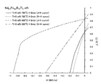
表6からわかるように、No.20〜25の試料では、残留磁束密度Br≧0.85T、固有保磁力HcJ≧480kA/m、最大エネルギ積(BH)max≧120kJ/m3の優れた硬磁気特性が得られた。
【0171】
図13は、No.21の試料とNo.26の試料の減磁曲線を示している。図13のグラフの縦軸は磁化を示し、横軸は減磁界の強度を示している。図13からわかるように、No.21の試料の減磁曲線の角形性はNo.26の試料の角形性に比較して極めて良好である。No.26の試料の場合、結晶粒径が大きいために角形性が劣化しているものと考えられる。
【0172】
次に、熱処理後における実施例の各試料について、Cu−Kαの特性X線を用いて構成相を調査し、TEMを用いて結晶サイズを測定した。その結果、R2Fe14B相の平均結晶粒径は20〜100nmの範囲にあり、α−Fe相および鉄基ホウ化物相の平均結晶粒径は10〜50nmの範囲にあった。
【0173】
一方、No.26およびNo.28の試料の場合、熱処理の前後で構成相の種類に差は生じなかったが、試料No.27の場合、R2Fe14B型化合物相に加え、α−Fe相およびFe23B6の析出・成長が確認された。
【0174】
以上のことから、急冷雰囲気圧は30kPa以上にすることが好ましく、また、急冷雰囲気を30kPa以上にする場合はロール表面速度を10m/秒以上30m/秒以下にすることが好ましい。
【0175】
【発明の効果】
本発明によれば、Tiを添加した合金溶湯の急冷を行なうことにより、磁石に必要な希土類元素の量を低減しながら保磁力および磁化が充分に高く優れた磁気特性を発揮する永久磁石が得られる。
【0176】
また、本発明によれば、Tiを添加することにより、液体急冷法を用いて急冷合金を作製する際に、冷却速度を低下させても、液体冷却工程時のα−Fe相の析出が抑制される。したがって、ストリップキャスト法のように比較的冷却速度が遅く、量産化に適した液体急冷法を用いることが可能になるため、製造コストの低減に極めて有効である。
【図面の簡単な説明】
【図1】Tiが添加されていないNd−Fe−Bナノコンポジット磁石の最大磁気エネルギ積(BH)maxと硼素濃度との関係を示すグラフである。グラフ中、白いバーは10〜14at%のNdを含有する試料のデータを示し、黒いバーは8〜10at%のNdを含有する試料のデータを示している。
【図2】Tiが添加されたNd−Fe−Bナノコンポジット磁石の最大磁気エネルギ積(BH)maxと硼素濃度との関係を示すグラフである。グラフ中、白いバーは10〜14at%のNdを含有する試料のデータを示し、黒いバーは8〜10at%のNdを含有する試料のデータを示している。
【図3】大気雰囲気ガスによる二次冷却効果を示す図である。横軸は冷却過程開始からの経過時間(Time)を示し、縦軸は冷却されつつある合金の温度(Temperature)を示している。
【図4】本発明による磁石におけるR2Fe14B型化合物相と(Fe、Ti)−B相を示す模式図である。
【図5】Tiを添加した場合、および、Tiに代えてNbなどを添加した場合における急冷凝固合金の結晶化過程における微細組織の変化を模式的に示す図である。
【図6】(a)は、本発明による鉄基希土類合金磁石のための急冷合金を製造する方法に用いる装置の全体構成例を示す断面図であり、(b)は急冷凝固が行われる部分の拡大図である。
【図7】No.2およびNo.3の試料(実施例)とNo.11の試料(比較例)の減磁曲線を示すグラフである。
【図8】No.2およびNo.3の試料とNo.11の試料の熱処理後におけるX線回折パターンを示すグラフである。
【図9】No.14およびNo.19の試料の減磁曲線を示すグラフである。
【図10】No.14の熱処理前後におけるX線回折パターンを示すグラフである。
【図11】No.19の試料の熱処理前後におけるX線回折パターンを示すグラフである。
【図12】No.21の試料の急冷合金(結晶化熱処理前)におけるX線回折パターンと、結晶化熱処理(640℃6分)後におけるX線回折パターンを示すグラフである。縦軸は回折ピークの強度(Intensity)、横軸は回折角度である。
【図13】No.21の試料とNo.26の試料の減磁曲線を示すグラフである。
【符号の説明】
1b、2b、8b、および9b 雰囲気ガス供給口
1a、2a、8a、および9a ガス排気口
1 溶解室
2 急冷室
3 溶解炉
4 貯湯容器
5 出湯ノズル
6 ロート
7 回転冷却ロール
21 溶湯
22 合金薄帯[0001]
BACKGROUND OF THE INVENTION
The present invention relates to a method for manufacturing a permanent magnet that is suitably used for various motors and actuators, and more particularly to a method for manufacturing an iron-based rare earth alloy magnet having a plurality of ferromagnetic phases.
[0002]
[Prior art]
In recent years, further improvement in performance and reduction in size and weight have been required for home appliances, OA devices, electrical components, and the like. Therefore, for permanent magnets used in these devices, it is required to maximize the performance-to-weight ratio of the entire magnetic circuit. For example, residual magnetic flux density B r Is required to use a permanent magnet of 0.5T (Tesla) or more. However, depending on the conventional relatively inexpensive hard ferrite magnet, the residual magnetic flux density B r Cannot be 0.5T or more.
[0003]
Currently, high residual magnetic flux density B of 0.5T or more r As permanent magnets having Sm-Co, Sm-Co magnets produced by powder metallurgy are known. Other than Sm-Co magnets, Nd-Fe-B magnets produced by powder metallurgy and Nd-Fe-B quenching magnets produced by liquid quenching have a high residual magnetic flux density B. r Can be demonstrated. The former Nd—Fe—B type magnet is disclosed in, for example, Japanese Patent Laid-Open No. 59-46008, and the latter Nd—Fe—B type rapidly cooled magnet is disclosed in, for example, Japanese Patent Laid-Open No. 60-9852. Yes.
[0004]
[Problems to be solved by the invention]
However, Sm-Co magnets have the disadvantage of high magnet prices because both Sm and Co as raw materials are expensive.
[0005]
Nd-Fe-B magnets contain inexpensive Fe as a main component (about 60% to 70% by weight of the total), and are therefore less expensive than Sm-Co magnets. There is a problem that the cost required is high. One of the reasons for the high manufacturing process cost is that a large-scale facility and a large number of processes are required for the separation and purification of Nd, in which the content is about 10 atomic% to 15 atomic%, and the reduction reaction. In addition, in the case of the powder metallurgy method, the number of manufacturing steps is inevitably increased.
[0006]
On the other hand, an Nd—Fe—B type quenching magnet manufactured by a liquid quenching method can be obtained by a relatively simple process such as a melting process → a liquid cooling process → a heat treatment process. There is an advantage that the process cost is lower than that of the system magnet. However, in the case of the liquid quenching method, in order to obtain a bulk permanent magnet, it is necessary to mix a magnet powder made from a quenching alloy with a resin to form a bonded magnet. The filling rate (volume ratio) is at most about 80%. Moreover, the quenched alloy produced by the liquid quenching method is magnetically isotropic.
[0007]
For the above reasons, the Nd—Fe—B type quenching magnet manufactured by using the liquid quenching method has a B higher than the anisotropic Nd—Fe—B type sintered magnet manufactured by the powder metallurgy method. r Has the problem of low.
[0008]
The method for improving the characteristics of the Nd—Fe—B quenching magnet is selected from the group consisting of Zr, Nb, Mo, Hf, Ta, and W as described in Japanese Patent Laid-Open No. 1-7502. It is effective to add at least one element combined with at least one element selected from the group consisting of Ti, V, and Cr. By adding such elements, the coercive force H cJ And corrosion resistance are improved, but residual magnetic flux density B r There is no known effective method for improving the thickness other than increasing the density of the bonded magnet.
[0009]
In the case of an Nd-Fe-B magnet, the composition of the rare earth element is relatively low, that is, Nd 3.8 Fe 77.2 B 19 (Atom%) near composition, Fe Three Magnet materials having a B-type compound as the main phase have been proposed (R. Coehoorn et al., J. de Phys, C8, 1998, pages 669-670). This permanent magnet material is obtained by applying a crystallization heat treatment to an amorphous alloy produced by a liquid quenching method, thereby producing Fe which is soft magnetic. Three Nd which is B phase and hard magnetic 2 Fe 14 It has a metastable structure formed from a fine crystal aggregate in which the B phase is mixed, and is called a “nanocomposite magnet”. For such a nanocomposite magnet, a high residual magnetic flux density B of 1T or more r Has been reported to have a coercive force H cJ Is relatively low at 160 kA / m to 240 kA / m. Therefore, the use of this permanent magnet material is limited to applications where the operating point of the magnet is 1 or more.
[0010]
In addition, attempts have been made to improve various magnetic elements by adding various metal elements to the raw material alloy of the nanocomposite magnet (JP-A-3-261104, US Pat. No. 4,836,868, JP-A-7-122212, International publication WO003 / 03403, WCChan, et.al. "THE EFFECTS OF REFRACTORY METALS ON THE MAGNETIC PROPERTIES OF α-Fe / R 2 Fe 14 B-TYPE NANOCOMPOSITES ", IEEE, Trans. Magn. No. 5, INTERMAG. 99, Kyongiu, Korea pp.3265-3267, 1999).
[0011]
The present invention has been made in view of the above circumstances, and its object is to provide a high coercive force (for example, H cJ ≥480 kA / m) while maintaining residual magnetic flux density B r An object of the present invention is to provide a method for producing a permanent magnet capable of producing an iron-based alloy magnet having excellent magnetic characteristics satisfying ≧ 0.85T at low cost.
[0012]
[Means for Solving the Problems]
The iron-based rare earth alloy magnet according to the present invention has the composition formula (Fe 1-m T m ) 100-xyz Q x R y M z (T is one or more elements selected from the group consisting of Co and Ni, Q is one or more elements selected from the group consisting of B and C, and R is one type substantially free of La and Ce. The above rare earth metal element, M is a metal element selected from the group consisting of Ti, Zr, and Hf, and is represented by at least one metal element that necessarily contains Ti), and the composition ratios x, y, z, and m satisfies 10 <x ≦ 20 atomic%, 6 ≦ y <10 atomic%, 0.1 ≦ z ≦ 12 atomic%, and 0 ≦ m ≦ 0.5, and two or more types of ferromagnetic crystals The hard magnetic phase has an average size of 10 nm to 200 nm and the soft magnetic phase has an average size of 1 nm to 100 nm.
[0013]
In a preferred embodiment, the composition ratios x, y, z, and m satisfy 10 <x <17 at%, 8 ≦ y ≦ 9.3 at%, and 0.5 ≦ z ≦ 6 at%, respectively.
[0014]
In certain preferred embodiments, R 2 Fe 14 The B-type compound phase, boride phase, and α-Fe phase are mixed in the same metal structure.
[0015]
In a preferred embodiment, the α-Fe phase and the boride phase have an average crystal grain size of 1 nm or more and 50 nm or less.
[0016]
In a preferred embodiment, the boride phase includes a ferromagnetic iron-based boride.
[0017]
In a preferred embodiment, the iron-based boride is Fe Three B and / or Fe twenty three B 6 Is included.
[0018]
In a preferred embodiment, the composition ratios x and z satisfy z / x ≧ 0.1.
[0019]
In a preferred embodiment, the R composition ratio y is 9.5 atomic% or less.
[0020]
In a preferred embodiment, the composition ratio y of R is 9.0 atomic% or less.
[0021]
In a preferred embodiment, it has a ribbon shape with a thickness of 10 μm to 300 μm.
[0022]
The iron-based rare earth alloy magnet may be powdered. In this case, the average particle size of the powder particles is preferably 30 μm or more and 250 μm or less.
[0023]
In a preferred embodiment, the coercivity H cJ ≧ 480 kA / m, residual magnetic flux density B r A magnet having hard magnetic properties of ≧ 0.7T is obtained.
[0024]
In a further preferred embodiment, the residual magnetic flux density Br ≧ 0.85 T, the maximum energy product (BH) max ≧ 120 kJ / m Three , Intrinsic coercive force H cJ A magnet having hard magnetic properties of ≧ 480 kA / m is obtained.
[0025]
The bonded magnet according to the present invention is obtained by molding a magnet powder containing the iron-based rare earth alloy magnet powder with a resin.
[0026]
The quenched alloy for iron-based rare earth alloy magnets according to the present invention has a composition formula of (Fe 1-m T m ) 100-xyz Q x R y M z (T is one or more elements selected from the group consisting of Co and Ni, Q is one or more elements selected from the group consisting of B and C, and R is one kind substantially free of La and Ce. The above rare earth metal element, M is a metal element selected from the group consisting of Ti, Zr, and Hf, and is represented by at least one metal element that necessarily contains Ti), and the composition ratios x, y, z, and m satisfies 10 <x ≦ 20 atomic%, 6 ≦ y <10 atomic%, 0.1 ≦ z ≦ 12 atomic%, and 0 ≦ m ≦ 0.5, respectively.
[0027]
In a preferred embodiment, α-Fe is substantially free of R 2 Fe 14 It has a structure including a B-type compound phase and an amorphous phase, and the R 2 Fe 14 The B-type compound phase accounts for 60% or more of the total volume.
[0028]
In a preferable embodiment, R satisfying 10 <x <17 at%, 8 ≦ y ≦ 9.3 at%, and 0.5 ≦ z ≦ 6 at% and having an average particle size of 50 nm or less. 2 Fe 14 A B-type compound phase is contained in an amount of 60% by volume or more.
[0029]
The quenched alloy for an iron-based rare earth alloy magnet according to the present invention is an alloy containing Fe, Q (Q is one or more elements selected from the group consisting of B and C), R (R is a rare earth element), and Ti. It is produced by cooling the molten metal, contains an amorphous phase, and R before the start of growth of the α-Fe crystal phase by heat treatment. 2 Fe 14 It has a structure that initiates the growth of a compound crystal phase having a B-type crystal structure.
[0030]
An iron-based rare earth alloy magnet manufacturing method according to the present invention includes an alloy containing Fe, Q (Q is one or more elements selected from the group consisting of B and C), R (R is a rare earth element), and Ti. A step of producing a molten metal, a step of cooling the molten alloy, producing a solidified alloy containing an amorphous phase, and heating the solidified alloy, 2 Fe 14 A step of starting growth of a compound crystal phase having a B-type crystal structure and then starting growth of an α-Fe crystal phase.
[0031]
In a preferred embodiment, the molten alloy is cooled using a strip casting method.
[0032]
The method for producing an iron-based rare earth alloy magnet according to the present invention has a composition formula of (Fe 1-m T m ) 100-xyz Q x R y M z (T is one or more elements selected from the group consisting of Co and Ni, Q is one or more elements selected from the group consisting of B and C, and R is one kind substantially free of La and Ce. The above rare earth metal element, M is a metal element selected from the group consisting of Ti, Zr, and Hf, and is represented by at least one metal element that necessarily contains Ti), and the composition ratios x, y, z, and a step of producing a molten alloy in which m satisfies 10 <x ≦ 20 atomic%, 6 ≦ y <10 atomic%, 0.1 ≦ z ≦ 12 atomic%, and 0 ≦ m ≦ 0.5, respectively. By rapidly cooling the molten alloy, R 2 Fe 14 A cooling step for producing a quenched alloy in which a B-type crystal phase and an amorphous phase are mixed, and the quenched alloy is crystallized, thereby containing two or more types of ferromagnetic crystal phases, and the average size of the hard magnetic phase is 10 nm or more Forming a structure having an average size of 200 nm or less and a soft magnetic phase in the range of 1 nm to 100 nm.
[0033]
In a preferred embodiment, in the cooling step, the volume ratio of R is 60% or more. 2 Fe 14 A quenched alloy containing a B-type compound phase is prepared.
[0034]
In a preferred embodiment, in the cooling step, the molten alloy is rapidly cooled in an atmospheric gas having a pressure of 30 kPa or more, and an R having an average particle size of 50 nm or less. 2 Fe 14 Producing a quenched alloy containing a B-type compound phase.
[0035]
In a preferred embodiment, the cooling step includes a step of bringing the molten alloy into contact with the surface of a rotating cooling roll to form an alloy in a supercooled liquid state, and the alloy in the supercooled state is separated from the cooling roll. After that, the atmosphere gas takes heat from the supercooled alloy, and the R 2 Fe 14 And a step of growing a B-type compound phase.
[0036]
In a preferred embodiment, the quenching alloy is subjected to a crystallization heat treatment, and at least R 2 Fe 14 Forming a structure containing three or more crystal phases including a B-type compound phase, an α-Fe phase, and a boride phase; 2 Fe 14 Including a step of setting an average crystal grain size of the B-type compound phase to 20 nm or more and 150 nm or less, and an average crystal grain size of the α-Fe phase and the boride phase of 1 nm to 50 nm.
[0037]
In a preferred embodiment, the boride phase includes a ferromagnetic iron-based boride.
[0038]
In a preferred embodiment, the iron-based boride is Fe Three B and / or Fe twenty three B 6 Is included.
[0039]
In a preferred embodiment, the molten alloy is cooled using a strip cast process.
[0040]
The method of manufacturing a bonded magnet according to the present invention includes a step of preparing a powder of an iron-based rare earth alloy magnet produced by any one of the above-described methods of manufacturing an iron-based rare earth alloy magnet, and using the powder of the iron-based rare earth alloy magnet. Producing a bonded magnet.
[0041]
In a preferable embodiment, the surface of the powder is subjected to a surface treatment.
[0042]
In a preferred embodiment, the bonded magnet is subjected to a surface treatment.
[0043]
DETAILED DESCRIPTION OF THE INVENTION
The iron-based rare earth alloy magnet of the present invention is formed from a rapidly cooled alloy that is solidified by cooling a molten rare earth-iron-boron alloy containing Ti. This rapidly solidified alloy contains a crystal phase, but is heated as necessary to further promote crystallization.
[0044]
By adding Ti to an iron-based rare earth alloy having a composition in a specific range, the present inventor suppresses precipitation and growth of an α-Fe phase that is likely to occur during the cooling process of the molten alloy, and is responsible for hard magnetic properties. 2 Fe 14 The inventors have found that the crystal growth of the B-type compound phase can proceed preferentially and uniformly, and have come up with the present invention.
[0045]
When Ti is not added, Nd 2 Fe 14 Prior to the precipitation and growth of the B phase, the α-Fe phase precipitates and tends to grow. Therefore, the soft magnetic α-Fe phase is coarsened at the stage where the crystallization heat treatment for the quenched alloy is completed.
[0046]
On the other hand, when Ti is added, the kinetics of precipitation / growth of the α-Fe phase is slow, and it takes time for the precipitation / growth. Therefore, before the precipitation / growth of the α-Fe phase is completed. Nd 2 Fe 14 It is considered that the precipitation and growth of the B phase starts. For this reason, before the α-Fe phase becomes coarse, Nd 2 Fe 14 B phase grows greatly in a uniformly dispersed state. In addition, Ti has a strong affinity for B and seems to be easily concentrated in the iron-based boride. It is believed that Ti addition stabilizes the iron-based boride due to the strong bonding of Ti and B within the iron-based boride.
[0047]
According to the present invention, the soft magnetic phase such as iron-based boride and α-Fe phase is refined by the action of Ti, and Nd 2 Fe 14 Phase B is uniformly dispersed and Nd 2 Fe 14 The volume ratio of the B phase increases. As a result, the coercive force and magnetization (residual magnetic flux density) are increased, and the squareness of the demagnetization curve is improved.
[0048]
Hereinafter, the iron-based rare earth alloy magnet of the present invention will be described in more detail.
[0049]
The iron-based rare earth alloy magnet of the present invention preferably has the composition formula (Fe 1-m T m ) 100-xyz Q x R y M z It is expressed by Here, T is one or more elements selected from the group consisting of Co and Ni, Q is one or more elements selected from the group consisting of B (boron) and C (carbon), and R is La and Ce One or more rare earth metal elements substantially free of M, M is at least one metal element selected from the group consisting of Ti, Zr, and Hf, and necessarily contains Ti.
[0050]
X, y, z, and m that define the composition ratio are 10 <x ≦ 20 atomic%, 6 ≦ y <10 atomic%, 0.1 ≦ z ≦ 12 atomic%, and 0 ≦ m ≦ 0. It is preferable that the
[0051]
The iron-based rare earth alloy magnet of the present invention has the same level of magnetization (residual magnetic flux density) as that when Ti is not added even when the composition ratio of rare earth elements is less than 10 atomic% of the whole. The unexpected effect of maintaining or increasing and improving the squareness of the demagnetization curve is exhibited.
[0052]
In the iron-based rare earth alloy magnet of the present invention, since the size of the soft magnetic phase is fine, each constituent phase is bonded by exchange interaction, and hard R 2 Fe 14 Even if a soft magnetic phase such as iron-based boride or α-Fe is present in addition to the B-type compound phase, the alloy as a whole can exhibit excellent demagnetization curve squareness.
[0053]
The iron-based rare earth alloy magnet of the present invention is preferably R 2 Fe 14 It contains iron-based borides or α-Fe having a saturation magnetization equivalent to or higher than that of the B-type compound phase. This iron-based boride is, for example, Fe Three B (saturation magnetization 1.5T) or Fe twenty three B 6 (Saturation magnetization 1.6 T). Where R 2 Fe 14 The saturation magnetization of B is about 1.6T, and the saturation magnetization of α-Fe is 2.1T.
[0054]
Usually, when the composition ratio x of B exceeds 10 atomic% and the composition ratio y of the rare earth element R is in the range of 6 atomic% to 8 atomic%, R 2 Fe twenty three B Three Even when a raw material alloy having such a composition range is used, R is added by adding Ti as in the present invention. 2 Fe twenty three B Three Instead of R 2 Fe 14 B and Fe twenty three B 6 Or Fe Three Iron-based borides such as B can be produced. These iron-based borides contribute to the improvement of magnetization.
[0055]
According to the inventor's experiment, only when Ti is added, unlike the case where other types of metals such as V, Cr, Mn, Nb, and Mo are added, the magnetization does not decrease, but rather the magnetization is improved. I understood for the first time. Further, when Ti was added, the squareness of the demagnetization curve was particularly good as compared with the other additive elements described above.
[0056]
Moreover, such a Ti addition effect is remarkably exhibited when the B concentration exceeds 10 at%. Hereinafter, this point will be described with reference to FIG.
[0057]
FIG. 1 shows the maximum magnetic energy product (BH) of an Nd—Fe—B magnet to which no Ti is added. max 3 is a graph showing the relationship between the concentration of boron and boron. In the graph, white bars indicate data of samples containing 10 to 14 at% Nd, and black bars indicate data of samples containing 8 to 10 at% Nd. On the other hand, FIG. 2 shows the maximum magnetic energy product (BH) of the Nd—Fe—B magnet added with Ti. max 3 is a graph showing the relationship between the concentration of boron and boron. In the graph, white bars indicate data of samples containing 10 to 14 at% Nd, and black bars indicate data of samples containing 8 to 10 at% Nd.
[0058]
As can be seen from FIG. 1, in the sample to which Ti is not added, the maximum magnetic energy product (BH) increases as the boron content exceeds 10 at% regardless of the Nd content. max Has fallen. The degree of this decrease is greater when the Nd content is 10 to 14 at%. This tendency has been known for a long time, and Nd 2 Fe 14 In a permanent magnet having a B phase as a main phase, it has been considered preferable to set the amount of boron to 10 at% or less. For example, U.S. Pat. No. 4,836,868 discloses an example in which the boron concentration is 5 to 9.5 at%, and the boron concentration is preferably 4 at% or more and less than 12 at%, and more preferably 4 at% or more and 10 at% or less. Teach range.
[0059]
On the other hand, in the sample to which Ti was added, as can be seen from FIG. 2, the maximum magnetic energy product (BH) in a certain range in which boron exceeds 10 at%. max Has improved. This improvement is particularly remarkable when the Nd content is 8 to 10 at%.
[0060]
As described above, according to the present invention, it is possible to obtain an effect which cannot be expected from the conventional technical common knowledge that the magnetic properties deteriorate when the B concentration exceeds 10 at% by adding Ti.
[0061]
Next, a method for producing an iron-based rare earth alloy magnet according to the present invention will be described.
[0062]
According to the production method of the present invention, the molten iron-base alloy having the above-described composition is cooled in an inert atmosphere, whereby R 2 Fe 14 A quenched alloy containing 60% by volume or more of the B-type compound phase is produced. R in quenched alloys 2 Fe 14 The average size of the B-type compound phase is, for example, 80 nm or less. If the quenched alloy is subjected to heat treatment as necessary, the amorphous material remaining in the quenched alloy can be crystallized.
[0063]
In a preferred embodiment, the molten alloy is cooled in an atmosphere having a pressure of 30 kPa or more. Thereby, the molten alloy is not only rapidly cooled by contact with the cooling roll, but also appropriately cooled by receiving the secondary cooling effect by the atmospheric gas even after leaving the cooling roll.
[0064]
By appropriately adjusting the rotational peripheral speed of the cooling roll, it is possible to control the state of the alloy when leaving the cooling roll to the supercooled liquid state, and after the supercooled alloy leaves the cooling roll, The heat is removed by the atmospheric gas and crystallized.
[0065]
The secondary cooling effect by the atmospheric gas will be described with reference to FIG. FIG. 3 is a graph schematically showing the relationship between the elapsed time (Time) from the start of the cooling process and the alloy temperature (Temperature). The graph shows the cooling path a of the alloy when the atmospheric gas pressure is relatively high exceeding 30 kPa, and the cooling path b of the alloy when the atmospheric gas pressure is relatively low below 30 kPa. Α-Fe phase, Nd 2 Fe 14 B phase and Fe twenty three B 6 The phase precipitation region is illustrated. Where T m Is the melting point of the alloy, T g Is the glass transition temperature of the alloy.
[0066]
As can be seen from FIG. 3, when the atmospheric gas pressure is low (cooling path b), a large secondary cooling effect by the atmospheric gas cannot be expected, so the rotation speed of the cooling roll is increased and the cooling roll is rapidly cooled (primary cooling). The speed is relatively high. After leaving the surface of the cooling roll, the alloy is cooled at a relatively slow rate by the atmospheric gas (secondary cooling). The bent point of the cooling path b corresponds to the time when the alloy peels from the cooling roll.
[0067]
On the other hand, when the pressure of the atmospheric gas is relatively high (cooling path a), the cooling effect by the atmospheric gas (secondary cooling) is enhanced, and Nd 2 Fe 14 The time for passing through the region where the B phase is generated is shortened. For this, Nd 2 Fe 14 B phase growth is suppressed and fine Nd 2 Fe 14 It is estimated that phase B is obtained.
[0068]
Thus, when the atmospheric gas pressure is lowered so as to be less than 30 kPa, R generated in the quenched alloy. 2 Fe 14 Since the crystal grain size of the B-type compound phase becomes coarse, the finally obtained magnet characteristics are deteriorated.
[0069]
On the other hand, if the atmospheric gas pressure exceeds the normal pressure (atmospheric pressure) and becomes too high, the influence of the atmospheric gas trapped between the molten alloy and the cooling roll increases, and sufficient cooling by the cooling roll is achieved. It will not be done. As a result, coarse α-Fe precipitates and good hard magnetic properties cannot be obtained.
[0070]
According to the experiments by the present inventors, the pressure of the atmospheric gas during quenching is preferably controlled to 30 kPa or more and normal pressure (101.3 kPa) or less, and more preferably 30 kPa or more and 90 kPa or less. A more preferable range is 40 kPa or more and 60 kPa or less.
[0071]
Under the above atmospheric gas pressure, a preferable range of the roll surface peripheral speed is 4 meters / second (m / second) or more and 50 m / second or less. When the roll surface peripheral speed is slower than 4 m / sec, R contained in the quenched alloy 2 Fe 14 The crystal grains of the B-type compound phase will be coarsened. As a result, R 2 Fe 14 There is a possibility that the B-type compound phase becomes larger and the magnetic properties deteriorate.
[0072]
On the other hand, when the roll surface peripheral speed is higher than 50 m / sec, the quenched alloy becomes almost completely amorphous, and R 2 Fe 14 The B-type compound phase is hardly precipitated. Therefore, in crystallization heat treatment, R 2 Fe 14 Since the grain growth of the B-type compound phase is remarkable and the structure becomes non-uniform, the improvement of the magnetic properties cannot be achieved.
[0073]
According to experiments, a more preferable range of the peripheral surface speed of the roll is 5 m / sec or more and 30 m / sec or less, and a more preferable range is 5 m / sec or more and 20 m / sec or less.
[0074]
In the present invention, coarse α-Fe is hardly precipitated in the quenched alloy, and fine R 2 Fe 14 Structure with B-type compound phase or fine R 2 Fe 14 A structure in which a structure having a B-type compound phase and an amorphous phase are mixed is produced. As a result, it is possible to obtain a high-performance composite permanent magnet in which a soft magnetic phase such as an iron-based boride phase is finely dispersed or thinly spread between hard magnetic phases (grain boundaries) after heat treatment. it can. The “amorphous phase” in this specification is not only a phase constituted only by a part in which the atomic arrangement is completely disordered, but also a crystallization precursor, a microcrystal (size: several nm or less), or an atom It also includes phases that partially contain clusters. Specifically, a phase in which the crystal structure cannot be clearly identified by X-ray diffraction or transmission electron microscope observation will be widely referred to as an “amorphous phase”.
[0075]
Conventionally, a molten alloy having a composition similar to that which is the subject of the present invention is cooled and R 2 Fe 14 If an attempt is made to produce a rapidly quenched alloy containing 60% by volume or more of the B-type compound phase, an alloy structure in which a large amount of α-Fe is precipitated is obtained, so that α-Fe becomes coarse during the subsequent crystallization heat treatment. was there. When the soft magnetic phase such as α-Fe is coarsened, the magnet characteristics are greatly deteriorated, and a permanent magnet that can withstand practical use cannot be obtained.
[0076]
In particular, when the boron content is relatively high as in the raw material alloy composition used in the present invention, the crystal phase is difficult to be generated even if the cooling rate of the molten alloy is slow because of the high amorphous forming ability of boron. Therefore, according to the prior art, the cooling rate of the molten alloy is sufficiently reduced to reduce R 2 Fe 14 If an attempt is made to produce a rapidly solidified alloy in which the volume ratio of the B-type compound phase exceeds 60%, R 2 Fe 14 In addition to the B-type compound phase, a large amount of α-Fe or its precursor was precipitated, and the subsequent crystallization heat treatment caused the α-Fe phase to become coarse, resulting in a significant deterioration of the magnet characteristics.
[0077]
From the above, in order to increase the coercive force of nanocomposite magnets, the cooling rate of the molten alloy is increased so that most of the rapidly solidified alloy is occupied by the amorphous phase, and then from the amorphous phase. There has been common sense that it is preferable to form a uniformly refined structure by crystallization heat treatment. This is because, in order to obtain a nanocomposite having an alloy structure in which a fine crystal phase is dispersed, it was thought that crystallization should be performed from an amorphous phase in a heat treatment process that is easy to control.
[0078]
For this reason, La having excellent amorphous forming ability is added to a raw material alloy, and a rapidly solidified alloy having an amorphous phase as a main phase is prepared by quenching a molten metal of the raw material alloy, and then Nd is subjected to crystallization heat treatment. 2 Fe 14 A technique has been reported in which both the B phase and the α-Fe phase are precipitated and grown, and each phase is as fine as several tens of nanometers (WCChan, et.al. "THE EFFECTS OF REFRACTORY METALS ON THE MAGNETIC PROPERTIES OF α-Fe / R 2 Fe 14 B-TYPE NANOCOMPOSITES ", IEEE, Trans. Magn. No. 5, INTERMAG. 99, Kyongiu, Korea pp.3265-3267, 1999). This paper describes the addition of trace amounts of refractory metal elements such as Ti (2 at. Nd) improves the magnetic properties and increases the composition ratio of Nd, which is a rare earth element, from 19.5 at% to 11.0 at%. 2 Fe 14 It teaches that it is preferable to refine both the B phase and the α-Fe phase. The addition of the refractory metal is performed by using a boride (R 2 Fe twenty three B Three Or Fe Three B) is suppressed, Nd 2 Fe 14 This is performed to produce a magnet composed of only two phases of a B phase and an α-Fe phase.
[0079]
On the other hand, in the present invention, by the action of the added Ti, precipitation of α-Fe phase is suppressed in the rapid solidification step, and furthermore, soft magnetic phases such as iron-based boride and α-Fe phase in the crystallization heat treatment step are suppressed. The coarsening can be suppressed.
[0080]
According to the present invention, a permanent magnet having high magnetization (residual magnetic flux density) and coercive force and excellent squareness of a demagnetization curve while using a raw material alloy having a relatively small amount of rare earth elements (9.3 at% or less). Can be manufactured.
[0081]
As described above, the increase in the coercive force of the magnet according to the present invention is Nd. 2 Fe 14 B phase is preferentially precipitated and grown in the cooling process, thereby Nd 2 Fe 14 This is achieved by increasing the volume ratio of the B phase but suppressing the coarsening of the soft magnetic phase. Also, the increase in magnetization is caused by the action of Ti to generate a boride phase such as a ferromagnetic iron-based boride from the boron-rich nonmagnetic amorphous phase present in the rapidly solidified alloy, and the nonmagnetic remaining after the crystallization heat treatment This is considered to be obtained because the volume ratio of the amorphous phase was reduced.
[0082]
The quenched alloy obtained as described above is subjected to a crystallization heat treatment as necessary, and R 2 Fe 14 It is preferable to form a structure containing three or more kinds of crystal phases including a B-type compound phase, a boride phase, and an α-Fe phase. In this organization, R 2 Fe 14 The heat treatment temperature and time are adjusted so that the average crystal grain size of the B-type compound phase is 10 nm to 200 nm and the average crystal grain size of the boride phase and the α-Fe phase is 1 nm to 50 nm. R 2 Fe 14 The average crystal grain size of the B-type compound phase is usually 30 nm or more, but depending on the conditions, it is 50 nm or more. The average crystal grain size of a soft magnetic phase such as a boride phase or α-Fe phase is often 30 nm or less, and typically only a few nm.
[0083]
R in the final magnet 2 Fe 14 The average crystal grain size of the B-type compound phase is larger than the average crystal grain size of the α-Fe phase. FIG. 4 schematically shows the metal structure of this magnet. As can be seen from FIG. 4, a relatively large R 2 Fe 14 A fine soft magnetic phase is dispersed between the B-type compound phases. R like this 2 Fe 14 Even when the average size of the B-type compound phase is relatively large, since the average size of the soft magnetic phase is sufficiently small, the constituent phases are combined by exchange interaction, so that the magnetization direction of the soft magnetic phase is Since it is constrained by the hard magnetic phase, the entire alloy can exhibit excellent demagnetization curve squareness.
[0084]
In the production method of the present invention, the reason why the boride is likely to be generated as described above is that R 2 Fe 14 When a solidified alloy with the majority of the B-type compound phase is prepared, the amorphous phase present in the quenched alloy inevitably contains excessive boron, so this boron is combined with other elements in the crystallization heat treatment to precipitate and This is considered to be easy to grow. However, when boron and other elements contained in the amorphous phase before heat treatment are combined to produce a compound having low magnetization, the magnetization of the entire magnet is lowered.
[0085]
According to the inventor's experiment, only when Ti is added, unlike the case of adding other types of metals such as V, Cr, Mn, Nb, and Mo, the magnetization does not decrease, but rather the magnetization is improved. I found out that Further, when M (particularly Ti) was added, the squareness of the demagnetization curve was particularly good as compared with the other additive elements described above. From these facts, it is considered that Ti plays an especially important role in suppressing the formation of a boride having a low magnetization. In particular, when boron and Ti are relatively small in the composition range of the raw material alloy used in the present invention, an iron-based boride phase having ferromagnetism is likely to precipitate by heat treatment. In this case, boron contained in the non-magnetic amorphous phase is incorporated into the iron-based boride. As a result, the volume ratio of the non-magnetic amorphous phase remaining after the crystallization heat treatment decreases, and the ferromagnetic crystalline phase increases. , Residual magnetic flux density B r Is thought to improve.
[0086]
Hereinafter, this point will be described in more detail with reference to FIG.
[0087]
FIG. 5 is a diagram schematically showing changes in the microstructure in the crystallization process of the rapidly solidified alloy when Ti is added and when Nb or the like is added instead of Ti. When Ti is added, grain growth of each constituent phase is suppressed in a temperature region higher than the temperature at which α-Fe is precipitated, and excellent hard magnetic properties are maintained. On the other hand, when a metal element such as Nb, V, or Cr is added, the grain growth of each constituent phase proceeds remarkably in a relatively high temperature region where α-Fe precipitates, and exchange coupling of each constituent phase occurs. As a result, the squareness of the demagnetization curve is greatly reduced.
[0088]
First, the case where Nb, Mo, and W are added will be described. In this case, if the heat treatment is performed in a relatively low temperature region where α-Fe does not precipitate, it is possible to obtain good hard magnetic characteristics with excellent squareness of the demagnetization curve. However, in alloys that have been heat treated at such temperatures, R 2 Fe 14 It is presumed that the B-type fine crystal phase is dispersed in the non-magnetic amorphous phase, and the composition of the nanocomposite magnet is not formed. Further, when heat treatment is performed at a higher temperature, an α-Fe phase is precipitated from the amorphous phase. Unlike the case where Ti is added, the α-Fe phase grows rapidly and becomes coarse after precipitation. For this reason, the exchange coupling between each constituent phase becomes weak, and the squareness of the demagnetization curve is greatly deteriorated.
[0089]
On the other hand, when Ti is added, by heat treatment, R 2 Fe 14 A nanocomposite structure including a B-type crystal phase, an iron-based boride phase, an α-Fe phase, and an amorphous phase is obtained, and each constituent phase is uniformly refined. Further, when Ti is added, the growth of the α-Fe phase is suppressed.
[0090]
When V or Cr is added, these added metals are dissolved in Fe and are antiferromagnetically coupled with Fe, so that the magnetization is greatly reduced. Moreover, when V or Cr is added, grain growth accompanying heat treatment is not sufficiently suppressed, and the squareness of the demagnetization curve is deteriorated.
[0091]
Only when Ti is added in this manner, the coarsening of the α-Fe phase can be appropriately suppressed, and a ferromagnetic iron-based boride can be formed. Furthermore, Ti plays an important role together with boron and carbon as an element that delays the crystallization of the Fe primary crystal (γ-Fe that is transformed into α-Fe later) during liquid quenching and facilitates the formation of a supercooled liquid. The cooling rate when quenching the molten alloy is 10 2 ℃ / sec ~ 10 Five Even if a relatively low value of about ° C./second is used, R does not significantly precipitate α-Fe. 2 Fe 14 It becomes possible to produce a quenched alloy in which a B-type crystal phase and an amorphous phase are mixed. This is important for cost reduction because it makes it possible to adopt a strip casting method particularly suitable for mass production among various liquid quenching methods.
[0092]
As a method of obtaining a raw material alloy by rapidly cooling the molten alloy, the strip casting method in which the molten metal is poured directly from the tundish onto the cooling roll without controlling the molten metal flow rate by the nozzle orifice is a method with high productivity and low manufacturing cost. It is. In order to make a molten R-Fe-B rare earth alloy amorphous within a cooling rate range that can also be achieved by strip casting, it is usually necessary to add 10 atomic% or more of B (boron). When a large amount of B is added in this manner, after performing a crystallization heat treatment on the quenched alloy, in addition to the non-magnetic magnetic amorphous phase, coarse α-Fe or soft magnetic phase Nd 2 Fe twenty three B Three Since a phase precipitates, a homogeneous fine crystal structure cannot be obtained. As a result, the volume ratio of the ferromagnetic phase decreases, the magnetization decreases and Nd 2 Fe 14 The coercive force is greatly reduced due to the decrease in the ratio of the B phase. However, when Ti is added as in the present invention, the above-mentioned phenomenon is observed, and magnetization is unexpectedly improved.
[0093]
Note that Nd is higher than when the quenched alloy contains a large amount of amorphous phase. 2 Fe 14 In the state containing a large amount of B phase, it is easy to obtain a final magnetic characteristic. Nd in the rapidly solidified alloy 2 Fe 14 The volume ratio of the B phase is preferably half or more of the whole, specifically 60% by volume or more. This value of 60% by volume is measured by Mossbauer spectroscopy.
[0094]
[Reason for limiting composition]
Q is entirely composed of B (boron) or a combination of B and C (carbon). The atomic ratio of C to the total amount of Q is preferably 0.25 or less.
[0095]
When the composition ratio x of Q is 10 atomic% or less, the cooling rate during rapid cooling is 10 2 ℃ / sec ~ 10 Five When the temperature is relatively low, such as C / sec, R 2 Fe 14 It becomes difficult to produce a quenched alloy in which a B-type crystal phase and an amorphous phase are mixed, and even if heat treatment is performed after that, H of less than 480 kA / m cJ Can only be obtained. In addition, the strip casting method, which has a relatively low process cost among liquid quenching methods, cannot be adopted, and the price of the permanent magnet increases. On the other hand, when the composition ratio x of Q exceeds 20 atomic%, the volume ratio of the amorphous phase remaining after the crystallization heat treatment increases, and at the same time, the abundance ratio of α-Fe having the highest saturation magnetization in the constituent phases decreases. Residual magnetic flux density B r Will fall. From the above, the composition ratio x of Q is preferably set so as to be more than 10 atomic% and not more than 20 atomic%. A more preferable range of the composition ratio x is 10 atom% or more and 17 atom% or less.
[0096]
R is one or more elements selected from the group of rare earth elements (including Y). When La or Ce is present, the coercive force and the squareness deteriorate, so it is preferable that La and Ce are not substantially contained. However, when a very small amount of La or Ce (0.5 atomic% or less) exists as an unavoidable impurity, there is no problem in terms of magnetic characteristics. Therefore, when it contains 0.5 atomic% or less of La and Ce, it can be said that La and Ce are not substantially contained.
[0097]
More specifically, R preferably contains Pr or Nd as an essential element, and part of the essential element may be substituted with Dy and / or Tb. When the composition ratio y of R becomes less than 6 atomic% of the total, R required for the expression of coercive force 2 Fe 14 A compound phase having a B-type crystal structure does not sufficiently precipitate, and a coercive force H of 480 kA / m or more cJ Can not get. Further, when the R composition ratio y is 10 atomic% or more, the abundance of iron-based borides and α-Fe having ferromagnetism decreases. Therefore, the composition ratio y of the rare earth element R is preferably adjusted to a range of 6 atomic% to less than 10 atomic%, for example, 6 atomic% to 9.5 atomic%. A more preferable range of R is 8 atom% or more and 9.3 atom% or less, and a most preferable range of R is 8.3 atom% or more and 9.0 atom% or less.
[0098]
The additive metal element M essentially includes Ti, and may further contain Zr and / or Hf. Ti is an indispensable element for obtaining the above-described effect, and the coercive force H cJ And residual magnetic flux density B r Contributes to the improvement of the squareness of the demagnetization curve and the maximum energy product (BH) max To improve.
[0099]
When the composition ratio z of the metal element M is less than 0.5 atomic% of the whole, the effect of adding Ti is not sufficiently exhibited. On the other hand, if the composition ratio z of the metal element M exceeds 12 atomic% of the whole, the volume ratio of the amorphous phase remaining after the crystallization heat treatment increases, so the residual magnetic flux density B r It is easy to invite a decline. From the above, the composition ratio z of the metal element M is preferably in the range of 0.5 atomic% to 12 atomic%. A more preferable lower limit of the z range is 1.0 atomic%, and a more preferable upper limit of the z range is 8.0 atomic%. A more preferable upper limit of the range of z is 6.0 atomic%.
[0100]
Further, the higher the Q composition ratio x, the easier it is to form an amorphous phase containing excessive Q (for example, boron). Therefore, it is preferable to increase the composition ratio z of the metal element M. Specifically, it is preferable to adjust the composition ratio so as to satisfy z / x ≧ 0.1, and it is more preferable to satisfy z / x ≧ 0.15.
[0101]
In addition, since Ti functions especially preferable, it is preferable that the metal element M necessarily contains Ti. In this case, the ratio (atomic ratio) of Ti to the entire metal element M is preferably 70% or more, and more preferably 90% or more.
[0102]
Fe occupies the remainder of the elements described above, but desired hard magnetic properties can be obtained even if a part of Fe is replaced with one or two transition metal elements (T) of Co and Ni. When the substitution amount of T for Fe exceeds 50%, a high residual magnetic flux density B of 0.7 T or more r Cannot be obtained. For this reason, the substitution amount is preferably limited to a range of 0% to 50%. By replacing part of Fe with Co, the squareness of the demagnetization curve is improved and R 2 Fe 14 Since the Curie temperature of the B phase is increased, the heat resistance is improved. A preferable range of the amount of Fe substitution by Co is 0.5% or more and 40% or less.
[0103]
Next, a preferred embodiment of the present invention will be described.
[0104]
[Liquid quenching device]
In the present embodiment, for example, a raw material alloy is manufactured using a quenching apparatus shown in FIG. In order to prevent oxidation of the raw material alloy containing rare earth elements R and Fe which are easily oxidized, the alloy manufacturing process is performed in an inert gas atmosphere. As the inert gas, a rare gas such as helium or argon or nitrogen can be used. Note that since nitrogen is relatively easy to react with the rare earth element R, it is preferable to use a rare gas such as helium or argon.
[0105]
The apparatus shown in FIG. 6 includes a raw material
[0106]
As shown in FIG. 6 (a), the
[0107]
The quenching
[0108]
In this apparatus, the atmosphere in the
[0109]
The
[0110]
The hot
[0111]
The
[0112]
According to the apparatus shown in FIG. 6, for example, a total of 10 kg of the raw material alloy can be rapidly solidified in 10 to 20 minutes. The quenched alloy thus formed becomes, for example, an alloy ribbon (alloy ribbon) 22 having a thickness of 10 to 300 μm and a width of 2 to 3 mm.
[0113]
[Liquid quenching method]
First, the raw
[0114]
In the case of this embodiment, when the
[0115]
The time during which the
[0116]
In the present embodiment, the average particle size is adjusted by adjusting the roll surface speed within the range of 10 m / sec or more and 30 m / sec or less, and setting the atmospheric gas pressure to 30 kPa or higher in order to enhance the secondary cooling effect by the atmospheric gas. Fine R with a diameter of 80 nm or less 2 Fe 14 A quenched alloy containing 60% by volume or more of a B-type compound phase is produced.
[0117]
In addition, the rapid cooling method of the molten alloy used in the present invention is not limited to the above-described single roll method, but is a twin roll method, a gas atomizing method, a strip cast method that does not perform flow rate control by a nozzle or an orifice, A cooling method combining a method and a gas atomizing method may be used.
[0118]
Among the above rapid cooling methods, the cooling rate of the strip cast method is relatively low. 2 -10 Five ° C / second. In this embodiment, by adding an appropriate amount of Ti to the alloy, it is possible to form a quenched alloy in which most of the structure containing no Fe primary crystal is formed even by the strip casting method. The strip casting method is effective when producing a large amount of quenched alloy as compared with the single roll method because the process cost is about half or less of other liquid quenching methods, and is a technique suitable for mass production. When the element M is not added to the raw material alloy, or when Cr, V, Mn, Mo, Ta, and / or W is added instead of the element Ti, a quenched alloy is formed using a strip casting method. However, since a metal structure containing many Fe primary crystals is generated, a desired metal structure cannot be formed.
[0119]
[Heat treatment]
In the present embodiment, the heat treatment is performed in an argon atmosphere. Preferably, the heating rate is 5 ° C./second to 20 ° C./second, and the temperature is maintained at 550 ° C. to 850 ° C. for 30 seconds to 20 minutes, and then cooled to room temperature. By this heat treatment, fine crystals of metastable phase are precipitated and grown in the amorphous phase, and a nanocomposite structure is formed. According to the invention, Nd already fine at the start of heat treatment. 2 Fe 14 Since the B-type crystal phase is present in an amount of 60% by volume or more of the whole, the coarsening of the α-Fe phase and other crystal phases is suppressed, and Nd 2 Fe 14 Each constituent phase (soft magnetic phase) other than the B-type crystal phase is uniformly refined.
[0120]
When the heat treatment temperature is lower than 550 ° C., a large amount of amorphous phase remains even after the heat treatment, and the coercive force may not reach a sufficient level depending on the rapid cooling conditions. Moreover, when the heat treatment temperature exceeds 850 ° C., the grain growth of each constituent phase is remarkable, and the residual magnetic flux density B r Decreases, and the squareness of the demagnetization curve deteriorates. For this reason, the heat treatment temperature is preferably 550 ° C. or more and 850 ° C. or less, but the more preferable heat treatment temperature range is 570 ° C. or more and 820 ° C. or less.
[0121]
In the present invention, due to the secondary cooling effect by the atmospheric gas, a sufficient amount of Nd is contained in the quenched alloy. 2 Fe 14 The B-type compound phase is precipitated uniformly and finely. For this reason, even when the crystallization heat treatment is not performed on the quenched alloy, the rapidly solidified alloy itself can exhibit sufficient magnet characteristics. Therefore, the crystallization heat treatment is not an essential step in the present invention, but it is preferable to perform this for improving the magnet characteristics. It should be noted that the magnet characteristics can be sufficiently improved even by heat treatment at a lower temperature than in the past.
[0122]
The heat treatment atmosphere is preferably an inert gas atmosphere in order to prevent oxidation of the alloy. The heat treatment may be performed in a vacuum of 0.1 kPa or less.
[0123]
In the quenched alloy before heat treatment, R 2 Fe 14 In addition to the B-type compound phase and the amorphous phase, Fe Three B phase, Fe twenty three B 6 , And R 2 Fe twenty three B Three Metastable phases such as phases may be included. In that case, by heat treatment, R 2 Fe twenty three B Three The phase disappears and R 2 Fe 14 Iron-based borides exhibiting a saturation magnetization equivalent to or higher than the saturation magnetization of the B phase (for example, Fe twenty three B 6 ) And α-Fe can be grown.
[0124]
In the case of the present invention, even if a soft magnetic phase such as α-Fe is finally present, the soft magnetic phase and the hard magnetic phase are magnetically coupled by an exchange interaction, so that excellent magnetic properties are exhibited. Is done.
[0125]
R after heat treatment 2 Fe 14 The average crystal grain size of the B-type compound phase needs to be uniaxial crystal grain size of 300 nm or less, preferably 20 nm or more and 150 nm or less, and more preferably 20 nm or more and 100 nm or less. On the other hand, when the average crystal grain size of the boride phase or α-Fe phase exceeds 50 nm, the exchange interaction acting between the constituent phases is weakened, and the squareness of the demagnetization curve is deteriorated. (BH) max Will fall. When the average crystal grain size is less than 1 nm, a high coercive force cannot be obtained. From the above, the average crystal grain size of the soft magnetic phase such as boride phase or α-Fe phase is preferably 1 nm or more and 50 nm or less, and more preferably 30 nm or less.
[0126]
Note that the ribbon of the quenched alloy may be roughly cut or pulverized before the heat treatment.
[0127]
If the obtained magnet is finely pulverized after heat treatment to produce magnet powder (magnetic powder), various bonded magnets can be produced from the magnetic powder by known processes. When producing a bonded magnet, the iron-based rare earth alloy magnetic powder is mixed with an epoxy resin or a nylon resin and formed into a desired shape. At this time, the nanocomposite magnetic powder may be mixed with other types of magnetic powder, for example, Sm—Fe—N magnetic powder or hard ferrite magnetic powder.
[0128]
Various rotary machines, such as a motor and an actuator, can be manufactured using the above-mentioned bond magnet.
[0129]
When the magnetic powder of the present invention is used for an injection-molded bonded magnet, it is preferably pulverized so that the average particle size is 200 μm or less, and more preferably the average particle size of the powder is 30 μm or more and 150 μm or less. Moreover, when using for a compression-molded bond magnet, it is preferable to grind | pulverize so that a particle size may be 300 micrometers or less, and the average particle diameter of a more preferable powder is 30 micrometers or more and 250 micrometers or less. More preferably, the particle size distribution has two peaks and the average particle size is 50 μm or more and 200 μm or less.
[0130]
In addition, by performing surface treatment such as coupling treatment, chemical conversion treatment, and plating on the surface of the powder, the formability at the time of forming the bonded magnet and the corrosion resistance and heat resistance of the obtained bonded magnet can be improved regardless of the forming method. Further, when the surface of the bonded magnet after molding is subjected to surface treatment such as resin coating, chemical conversion treatment or plating, the corrosion resistance and heat resistance of the bonded magnet can be improved in the same manner as the powder surface treatment.
[0131]
【Example】
First, examples and comparative examples in which the composition ratio x of Q and the composition ratio z of M satisfy 10 <x <15 atomic% and 0.1 <z <10 atomic%, respectively, will be described.
[0132]
For each of the samples (No. 1 to No. 12) having the composition shown in Table 1, materials of B, C, Fe, Co, Ti, Nd, Pr, Tb, and Dy having a purity of 99.5% or more were used. And the total amount was 30 grams) and put into a quartz crucible. Here, Sample No. 1-No. 8 corresponds to an example of the present invention. 9-No. 12 corresponds to a comparative example.
[0133]
[Table 1]
In Table 1, for example, “B7 + C4” in the column labeled “Q” indicates that 7 atomic% B (boron) and 4 atomic% C (carbon) are added, and “R” is displayed. “
[0135]
Since the quartz crucible used for the preparation of the molten metal has an orifice with a diameter of 0.8 mm at the bottom, the raw material is melted in the quartz crucible and then melted into the molten alloy and dropped downward from the orifice. . The raw material was dissolved using a high-frequency heating method in an argon atmosphere with a pressure of 1.33 kPa. In this example, the molten metal temperature was set to 1500 ° C.
[0136]
By pressurizing the molten metal surface with Ar gas of 26.7 kPa, the molten metal was ejected to the outer peripheral surface of the copper roll located 0.7 mm below the orifice. The roll rotates at high speed while the inside is cooled so that the temperature of the outer peripheral surface is maintained at about room temperature. For this reason, the molten alloy dripped from the orifice comes into contact with the circumferential surface of the roll and is taken away in the circumferential speed direction while taking heat away. Since the molten alloy is continuously dropped onto the roll peripheral surface through the orifice, the alloy solidified by rapid cooling has a ribbon (width: 2 to 3 mm, thickness: 20 to 50 μm) extending in a thin strip shape. Will have.
[0137]
In the case of the rotating roll method (single roll method) employed in this embodiment, the cooling rate is defined by the roll peripheral speed and the molten metal flow rate per unit time. The amount of molten metal flowing down depends on the orifice diameter (cross-sectional area) and the molten metal pressure. In this example, the orifice was 0.8 mm in diameter, the melt pressure was 26.7 kPa, and the flow rate was about 0.5-1 kg / min.
[0138]
The roll peripheral speed was as shown in Table 1.
[0139]
Next, no. 1-No. Twelve quenched alloys were heat treated in Ar gas. Specifically, each quenched alloy was held for 6 minutes at the heat treatment temperature shown in the rightmost column of Table 1, and then cooled to room temperature. Thereafter, the magnetic properties of each sample were measured using a vibration type magnetometer. Table 2 below shows the measurement results.
[0140]
[Table 2]
As can be seen from Table 2, the magnetic properties of the examples were extremely excellent compared to the magnetic properties of the comparative example. Even when Ti is added, if the composition ratio y of the rare earth element R (Nd) is out of the range of 6 ≦ y <10 atomic%, the Ti addition effect of uniform refinement of the structure is not sufficiently exhibited, and the residual Magnetic flux density B r There was a marked decrease in the.
[0142]
FIG. 2 and no. 3 (Example) and No. 3 sample. 11 shows demagnetization curves of 11 samples (comparative examples). The vertical axis of the graph in FIG. 7 indicates the magnetization, and the horizontal axis indicates the strength of the demagnetizing field. As can be seen from FIG. 7, the squareness of the demagnetization curve of the example is very good compared to the squareness of the comparative example. In the case of the comparative example, it is considered that the squareness deteriorates due to the large crystal grain size.
[0143]
Next, with respect to each sample of the example, the constituent phase was examined by the characteristic X-ray of Cu-Kα. As a result, R 2 Fe 14 In addition to B phase, Fe twenty three B 6 Phase and α-Fe phase were confirmed. On the other hand, no. 9 and no. In the case of 10 samples (comparative example), R is hard magnetic 2 Fe 14 B type compound phase is not confirmed, R is a soft magnetic phase 2 Fe twenty three B Three It was found that a structure composed of and α-Fe was formed. No. In sample 11 (comparative example), R is a hard magnetic phase. 2 Fe 14 Although a mixed structure composed of B-phase and α-Fe, which is a soft magnetic phase, was formed, ferromagnetic iron-based borides could not be confirmed.
[0144]
FIG. 2 and no. 3 (Example) and No. 3 sample. 11 shows X-ray diffraction patterns after heat treatment of 11 samples (comparative examples). The vertical axis of the graph in FIG. 8 indicates the diffraction intensity, and the horizontal axis indicates the diffraction angle.
[0145]
As can be seen from FIG. 8, in the embodiment, Nd 2 Fe 14 B phase, α-Fe phase, and Fe twenty three B 6 A metallographic structure composed of phases was formed. On the other hand, in the comparative example, Nd 2 Fe 14 Only the B phase and the α-Fe phase are observed, and it is considered that B is excessively present in the alloy structure.
[0146]
In addition, No. 1-No. About each sample of 8, the metal structure after heat processing was investigated with the transmission electron microscope. As a result, each sample had a nanocrystal structure with an average crystal grain size of 10 nm to 25 nm or less. No. When the sample of 2 was analyzed with an atom probe, a part of Ti was replaced with Fe in each constituent phase, but most of Ti was present at the grain boundaries.
[0147]
Next, an example in which the composition ratio x of Q and the composition ratio z of M satisfy 15 ≦ x ≦ 20 atomic% and 3.0 <z <12 atomic%, respectively, and a reference example that is not satisfied will be described.
[0148]
For each of the samples (No. 13 to No. 19) having the composition shown in Table 3, the total amount is 30 g grams using materials of B, C, Fe, Co, Ti, and Nd having a purity of 99.5% or more) Was weighed so as to be and put into a quartz crucible.
[0149]
[Table 3]
In Table 3, for example, “Ti8” in the column labeled “M” indicates that 8 atomic% Ti has been added, and “−” indicates that Ti has not been added.
[0151]
Sample No. Also for samples 13 to 19, the above-mentioned sample No. The rapid solidification step was performed in the same manner as the conditions for 1-12.
[0152]
When the structure of the quenched alloy thus obtained was examined by the characteristic X-ray of CuKα, all the samples were amorphous alloys. The reason why the quenched alloy was amorphous is that the B concentration in the alloy was relatively high and it was easy to become amorphous.
[0153]
Next, no. 12-No. Nineteen quenched alloys were heat treated in Ar gas. Specifically, each quenched alloy was held for 6 minutes at the heat treatment temperature shown in the rightmost column of Table 3, and then cooled to room temperature. Thereafter, the magnetic properties of each sample were measured using a vibration type magnetometer. Table 4 below shows the measurement results.
[0154]
[Table 4]
As can be seen from Table 4, no. The magnetic characteristics of the samples 13 to 16 are No. It was excellent compared with the magnetic characteristics of the samples 17-19 (reference example).
[0156]
FIG. 13 and no. 17 shows demagnetization curves of 17 samples. The vertical axis of the graph in FIG. 9 indicates the magnetization, and the horizontal axis indicates the strength of the demagnetizing field. As can be seen from FIG. The squareness of the demagnetization curve of the 13 samples is No. 13. It is very good compared to the squareness of 17 samples.
[0157]
10 and FIG. 13 and no. 17 shows X-ray diffraction patterns before and after heat treatment of 17 samples.
[0158]
As can be seen from FIG. 10, in the case of adding Ti, a diffraction peak indicating crystallinity is not observed in the alloy before heat treatment (as-spun), but after heat treatment at 660 ° C. for 6 minutes, Nd 2 Fe 14 A diffraction peak indicating the formation of a compound phase having a B-type crystal structure is observed. At this time, a diffraction peak of the α-Fe phase is also observed, but its intensity is not large. When the heat treatment temperature is 780 ° C., the intensity of the diffraction peak of the α-Fe phase is relatively increased, and the crystallization temperature of the α-Fe phase is Nd. 2 Fe 14 It is estimated that it is higher than the crystallization temperature of B.
[0159]
In contrast, when Ti is not added, as shown in FIG. 11, after heat treatment at 600 ° C. for 6 minutes, Nd 2 Fe 14 A diffraction peak indicating the formation of a compound phase having a B-type crystal structure was not observed, and a diffraction peak of the α-Fe phase was clearly observed. This means that Nd 2 Fe 14 It shows that the α-Fe phase is precipitated and grown prior to the crystallization of the B phase. When the heat treatment temperature is 780 ° C., the intensity of the diffraction peak of the α-Fe phase is very strong, and the α-Fe phase is coarsened.
[0160]
Thus, when the composition ratio x of Q is 15 atomic% or more, it is preferable that the composition ratio z of M is larger than 3.0.
[0161]
Next, Nd 9 Fe 78.7 B 10.3 Ti 2 About the alloy which has a composition of (at%), the molten metal which changed quenching atmospheric pressure and roll surface speed was cooled.
[0162]
Since the quartz crucible used for the preparation of the molten metal has an orifice with a diameter of 0.8 mm at the bottom, the raw material is melted in the quartz crucible and then melted into the molten alloy and dropped downward from the orifice. . The raw material was dissolved using a high-frequency heating method in an argon atmosphere with a pressure of 1.33 kPa. In this example, the molten metal temperature was set to 1500 ° C.
[0163]
By pressurizing the molten metal surface with Ar gas of 26.7 kPa, the molten metal was caused to flow down to the outer peripheral surface of the copper roll located 0.7 mm below the orifice. Other conditions are almost the same as in the above-described embodiment.
[0164]
In this example, the quenching atmosphere pressure, the roll surface speed, and the heat treatment temperature were changed as shown in Table 5 below.
[0165]
[Table 5]
The structure of the quenched alloy produced by the above liquid quenching method was examined by the characteristic X-ray of Cu-Kα. No. In all
[0167]
No. Nd for 26 samples 2 Fe 14 B phase, α-Fe phase, and Fe twenty three B 6 A diffraction peak due to the phase was confirmed. In the sample No. 27, only the halo pattern was observed. In No. 28, a strong diffraction peak due to the α-Fe phase and Nd 2 Fe 14 A slight diffraction peak due to phase B was observed. Sample No. In the case of 26, many amorphous phases existed.
[0168]
Next, no. 20-No. 26 quenched alloys were heat treated in Ar gas. Specifically, each quenched alloy was held for 6 minutes at the heat treatment temperature shown in the rightmost column of Table 5 and then cooled to room temperature. Thereafter, the magnetic properties of each sample were measured using a vibration type magnetometer. Table 6 below shows the measurement results.
[0169]
[Table 6]
As can be seen from Table 6, no. For
[0171]
FIG. No. 21 sample and no. The demagnetization curve of 26 samples is shown. The vertical axis of the graph in FIG. 13 indicates the magnetization, and the horizontal axis indicates the strength of the demagnetizing field. As can be seen from FIG. The squareness of the demagnetization curve of the sample No. 21 is No. 21. Compared to the squareness of the 26 samples, it is very good. No. In the case of 26 samples, it is considered that the squareness is deteriorated due to the large crystal grain size.
[0172]
Next, for each sample of the example after the heat treatment, the constituent phases were investigated using Cu-Kα characteristic X-rays, and the crystal size was measured using TEM. As a result, R 2 Fe 14 The average crystal grain size of the B phase was in the range of 20 to 100 nm, and the average crystal grain size of the α-Fe phase and the iron-based boride phase was in the range of 10 to 50 nm.
[0173]
On the other hand, no. 26 and no. In the case of 28 samples, there was no difference in the types of constituent phases before and after the heat treatment. In case of 27, R 2 Fe 14 In addition to the B-type compound phase, α-Fe phase and Fe twenty three B 6 Precipitation / growth was confirmed.
[0174]
In view of the above, the quenching atmosphere pressure is preferably set to 30 kPa or more, and when the quenching atmosphere is set to 30 kPa or more, the roll surface speed is preferably set to 10 m / sec or more and 30 m / sec or less.
[0175]
【The invention's effect】
According to the present invention, a permanent magnet that exhibits excellent magnetic properties with sufficiently high coercive force and magnetization while reducing the amount of rare earth elements necessary for the magnet is obtained by quenching the molten alloy containing Ti. It is done.
[0176]
In addition, according to the present invention, by adding Ti, the precipitation of α-Fe phase during the liquid cooling step is suppressed even when the cooling rate is lowered when a quenched alloy is produced using the liquid quenching method. Is done. Therefore, the cooling rate is relatively slow like the strip casting method, and a liquid quenching method suitable for mass production can be used, which is extremely effective in reducing the manufacturing cost.
[Brief description of the drawings]
FIG. 1 shows the maximum magnetic energy product (BH) of a Nd—Fe—B nanocomposite magnet without addition of Ti. max 3 is a graph showing the relationship between the concentration of boron and boron. In the graph, white bars indicate data of samples containing 10 to 14 at% Nd, and black bars indicate data of samples containing 8 to 10 at% Nd.
FIG. 2 shows the maximum magnetic energy product (BH) of a Nd—Fe—B nanocomposite magnet doped with Ti. max 3 is a graph showing the relationship between the concentration of boron and boron. In the graph, white bars indicate data of samples containing 10 to 14 at% Nd, and black bars indicate data of samples containing 8 to 10 at% Nd.
FIG. 3 is a diagram showing a secondary cooling effect by atmospheric gas. The horizontal axis represents the elapsed time (Time) from the start of the cooling process, and the vertical axis represents the temperature of the alloy being cooled (Temperature).
FIG. 4 shows R in a magnet according to the present invention. 2 Fe 14 It is a schematic diagram which shows a B-type compound phase and a (Fe, Ti) -B phase.
FIG. 5 is a diagram schematically showing a change in microstructure in the crystallization process of a rapidly solidified alloy when Ti is added and when Nb or the like is added instead of Ti.
6A is a cross-sectional view showing an example of the overall configuration of an apparatus used in a method for producing a quenched alloy for an iron-based rare earth alloy magnet according to the present invention, and FIG. 6B is a portion where rapid solidification is performed. FIG.
FIG. 2 and no. 3 (Example) and No. 3 sample. It is a graph which shows the demagnetization curve of 11 samples (comparative example).
FIG. 2 and no. 3 and No. 3 It is a graph which shows the X-ray-diffraction pattern after the heat processing of 11 samples.
FIG. 14 and no. It is a graph which shows the demagnetization curve of 19 samples.
FIG. 14 is a graph showing X-ray diffraction patterns before and after the 14 heat treatment.
FIG. It is a graph which shows the X-ray-diffraction pattern before and behind heat processing of 19 samples.
FIG. It is a graph which shows the X-ray-diffraction pattern in the quenching alloy (before crystallization heat processing) of 21 samples, and the X-ray-diffraction pattern after crystallization heat processing (640
FIG. No. 21 sample and no. It is a graph which shows the demagnetization curve of 26 samples.
[Explanation of symbols]
1b, 2b, 8b, and 9b Atmospheric gas supply port
1a, 2a, 8a, and 9a gas outlet
1 Dissolution chamber
2 quenching room
3 Melting furnace
4 Hot water storage container
5 Hot water nozzle
6 funnel
7 Rotating cooling roll
21 Molten metal
22 Alloy ribbon
Claims (3)
10<x≦20原子%、
6≦y<10原子%、
0.5≦z≦12原子%、
0≦m≦0.5および
z/x≧0.1を満足し、
元素Mに対するTiの原子比率が70%以上であり、
R 2 Fe 14 B型化合物相からなる硬磁性相とα−Fe相または硼化物相からなる軟磁性相とを含有し、硬磁性相の平均結晶粒径が10nm以上200nm以下、軟磁性相の平均結晶粒径が1nm以上50nm以下の範囲内にあり、
前記硬磁性相は前記軟磁性相よりも大きく、硬磁性相であるR2Fe14B型化合物相が体積比率で全体の60%以上存在する鉄基希土類合金ナノコンポジット磁石。The composition formula is (Fe 1-m T m ) 100-xyz Q x R y M z (T is one or more elements selected from the group consisting of Co and Ni, Q is selected from the group consisting of B and C One or more elements, R is one or more rare earth elements substantially free of La and Ce, M is a metal element selected from the group consisting of Ti, Zr and Hf, and Ti must At least one kind of metal element), and the composition ratios x, y, z and m are respectively
10 <x ≦ 20 atomic%,
6 ≦ y <10 atomic%,
0.5 ≦ z ≦ 12 atomic%,
0 ≦ m ≦ 0.5 and z / x ≧ 0.1 are satisfied,
The atomic ratio of Ti to element M is 70% or more,
A hard magnetic phase composed of an R 2 Fe 14 B-type compound phase and a soft magnetic phase composed of an α-Fe phase or a boride phase , the average crystal grain size of the hard magnetic phase being 10 nm or more and 200 nm or less; The average crystal grain size is in the range of 1 nm to 50 nm,
The iron-based rare earth alloy nanocomposite magnet in which the hard magnetic phase is larger than the soft magnetic phase, and the R 2 Fe 14 B type compound phase, which is a hard magnetic phase, is present in a volume ratio of 60% or more.
10<x≦20原子%、
6≦y<10原子%、
0.5≦z≦12原子%、および
0≦m≦0.5を満足し、
元素Mに対するTiの原子比率が70%以上であり、
熱処理前におけるR2Fe14B型化合物相が体積比率で全体の60%以上存在する鉄基希土類合金ナノコンポジット磁石用急冷合金。The composition formula is (Fe 1-m T m ) 100-xyz Q x R y M z (T is one or more elements selected from the group consisting of Co and Ni, Q is selected from the group consisting of B and C One or more elements, R is one or more rare earth elements substantially free of La and Ce, M is a metal element selected from the group consisting of Ti, Zr and Hf, and Ti must At least one kind of metal element), and the composition ratios x, y, z and m are respectively
10 <x ≦ 20 atomic%,
6 ≦ y <10 atomic%,
0.5 ≦ z ≦ 12 atomic% and 0 ≦ m ≦ 0.5 are satisfied,
The atomic ratio of Ti to element M is 70% or more,
A rapidly cooled alloy for an iron-based rare earth alloy nanocomposite magnet in which the R 2 Fe 14 B type compound phase before heat treatment is present in a volume ratio of 60% or more.
Priority Applications (1)
| Application Number | Priority Date | Filing Date | Title |
|---|---|---|---|
| JP2001358767A JP3763774B2 (en) | 2000-05-24 | 2001-11-26 | Quenched alloy for iron-based rare earth alloy magnet and method for producing iron-based rare earth alloy magnet |
Applications Claiming Priority (9)
| Application Number | Priority Date | Filing Date | Title |
|---|---|---|---|
| JP2000152234 | 2000-05-24 | ||
| JP2000-152234 | 2000-05-24 | ||
| JP2000-201999 | 2000-07-04 | ||
| JP2000201999 | 2000-07-04 | ||
| JP2000224519 | 2000-07-25 | ||
| JP2000-224519 | 2000-07-25 | ||
| JP2000291485 | 2000-09-26 | ||
| JP2000-291485 | 2000-09-26 | ||
| JP2001358767A JP3763774B2 (en) | 2000-05-24 | 2001-11-26 | Quenched alloy for iron-based rare earth alloy magnet and method for producing iron-based rare earth alloy magnet |
Related Parent Applications (1)
| Application Number | Title | Priority Date | Filing Date |
|---|---|---|---|
| JP2001149065A Division JP3264664B1 (en) | 2000-05-24 | 2001-05-18 | Permanent magnet having a plurality of ferromagnetic phases and manufacturing method thereof |
Publications (3)
| Publication Number | Publication Date |
|---|---|
| JP2002212686A JP2002212686A (en) | 2002-07-31 |
| JP2002212686A5 JP2002212686A5 (en) | 2005-10-20 |
| JP3763774B2 true JP3763774B2 (en) | 2006-04-05 |
Family
ID=27531558
Family Applications (1)
| Application Number | Title | Priority Date | Filing Date |
|---|---|---|---|
| JP2001358767A Expired - Fee Related JP3763774B2 (en) | 2000-05-24 | 2001-11-26 | Quenched alloy for iron-based rare earth alloy magnet and method for producing iron-based rare earth alloy magnet |
Country Status (1)
| Country | Link |
|---|---|
| JP (1) | JP3763774B2 (en) |
Cited By (1)
| Publication number | Priority date | Publication date | Assignee | Title |
|---|---|---|---|---|
| JP2003224010A (en) * | 2001-11-20 | 2003-08-08 | Sumitomo Special Metals Co Ltd | Compound for rare earth based bonded magnet and bonded magnet using the same |
Families Citing this family (2)
| Publication number | Priority date | Publication date | Assignee | Title |
|---|---|---|---|---|
| AU2002366140A1 (en) * | 2001-11-22 | 2003-06-10 | Sumitomo Special Metals Co., Ltd. | Nanocomposite magnet |
| JP7303157B2 (en) * | 2020-06-01 | 2023-07-04 | トヨタ自動車株式会社 | Rare earth magnet and manufacturing method thereof |
-
2001
- 2001-11-26 JP JP2001358767A patent/JP3763774B2/en not_active Expired - Fee Related
Cited By (1)
| Publication number | Priority date | Publication date | Assignee | Title |
|---|---|---|---|---|
| JP2003224010A (en) * | 2001-11-20 | 2003-08-08 | Sumitomo Special Metals Co Ltd | Compound for rare earth based bonded magnet and bonded magnet using the same |
Also Published As
| Publication number | Publication date |
|---|---|
| JP2002212686A (en) | 2002-07-31 |
Similar Documents
| Publication | Publication Date | Title |
|---|---|---|
| KR100562681B1 (en) | Permanent magnet including multiple ferromagnetic phases and method for producing the magnet | |
| JP4023138B2 (en) | Compound containing iron-based rare earth alloy powder and iron-based rare earth alloy powder, and permanent magnet using the same | |
| KR100535943B1 (en) | Iron-based rare earth alloy nanocomposite magnet and method for producing the same | |
| KR100535945B1 (en) | Nanocomposite magnet | |
| JP4766045B2 (en) | Iron-based rare earth nanocomposite magnet and manufacturing method thereof | |
| JP4687662B2 (en) | Iron-based rare earth alloy magnet | |
| JP3488358B2 (en) | Method for producing microcrystalline permanent magnet alloy and permanent magnet powder | |
| JP3801456B2 (en) | Iron-based rare earth permanent magnet alloy and method for producing the same | |
| JP3264664B1 (en) | Permanent magnet having a plurality of ferromagnetic phases and manufacturing method thereof | |
| JP4788300B2 (en) | Iron-based rare earth alloy nanocomposite magnet and manufacturing method thereof | |
| JP3763774B2 (en) | Quenched alloy for iron-based rare earth alloy magnet and method for producing iron-based rare earth alloy magnet | |
| JP4670179B2 (en) | Permanent magnet having a plurality of ferromagnetic phases and method for producing the same | |
| JP4715245B2 (en) | Iron-based rare earth nanocomposite magnet and method for producing the same | |
| JP3773484B2 (en) | Nano composite magnet | |
| JP2002064009A (en) | Iron-based rare earth alloy magnet and method of manufacturing the same | |
| JP2003286548A (en) | Rapidly cooled alloy for nano-composite magnet and production method therefor | |
| JP2003158005A (en) | Nanocomposite magnet and its manufacturing method | |
| JP3583116B2 (en) | Iron-based rare earth alloy magnet and method of manufacturing the same | |
| JP2007201102A (en) | Iron group rare-earth permanent magnet and manufacturing method therefor | |
| JP3625821B6 (en) | Nanocomposite magnet and method for manufacturing the same | |
| JP3625821B2 (en) | Nanocomposite magnet and method for manufacturing the same | |
| JP2002080921A (en) | Raw material alloy for iron-based rare earth alloy magnet and its production method | |
| JP2003286547A (en) | Rapid cooled alloy for nano-composite magnet | |
| JP2001288546A (en) | Iron-based alloy magnet and manufacturing method |
Legal Events
| Date | Code | Title | Description |
|---|---|---|---|
| A521 | Written amendment |
Free format text: JAPANESE INTERMEDIATE CODE: A523 Effective date: 20050624 |
|
| A621 | Written request for application examination |
Free format text: JAPANESE INTERMEDIATE CODE: A621 Effective date: 20050624 |
|
| A871 | Explanation of circumstances concerning accelerated examination |
Free format text: JAPANESE INTERMEDIATE CODE: A871 Effective date: 20050624 |
|
| A975 | Report on accelerated examination |
Free format text: JAPANESE INTERMEDIATE CODE: A971005 Effective date: 20050721 |
|
| A131 | Notification of reasons for refusal |
Free format text: JAPANESE INTERMEDIATE CODE: A131 Effective date: 20050802 |
|
| A521 | Written amendment |
Free format text: JAPANESE INTERMEDIATE CODE: A523 Effective date: 20050926 |
|
| A131 | Notification of reasons for refusal |
Free format text: JAPANESE INTERMEDIATE CODE: A131 Effective date: 20051025 |
|
| A521 | Written amendment |
Free format text: JAPANESE INTERMEDIATE CODE: A523 Effective date: 20051215 |
|
| TRDD | Decision of grant or rejection written | ||
| A01 | Written decision to grant a patent or to grant a registration (utility model) |
Free format text: JAPANESE INTERMEDIATE CODE: A01 Effective date: 20060117 |
|
| A61 | First payment of annual fees (during grant procedure) |
Free format text: JAPANESE INTERMEDIATE CODE: A61 Effective date: 20060117 |
|
| R150 | Certificate of patent or registration of utility model |
Free format text: JAPANESE INTERMEDIATE CODE: R150 Ref document number: 3763774 Country of ref document: JP Free format text: JAPANESE INTERMEDIATE CODE: R150 |
|
| S111 | Request for change of ownership or part of ownership |
Free format text: JAPANESE INTERMEDIATE CODE: R313111 |
|
| FPAY | Renewal fee payment (event date is renewal date of database) |
Free format text: PAYMENT UNTIL: 20090127 Year of fee payment: 3 |
|
| R350 | Written notification of registration of transfer |
Free format text: JAPANESE INTERMEDIATE CODE: R350 |
|
| FPAY | Renewal fee payment (event date is renewal date of database) |
Free format text: PAYMENT UNTIL: 20100127 Year of fee payment: 4 |
|
| FPAY | Renewal fee payment (event date is renewal date of database) |
Free format text: PAYMENT UNTIL: 20110127 Year of fee payment: 5 |
|
| FPAY | Renewal fee payment (event date is renewal date of database) |
Free format text: PAYMENT UNTIL: 20120127 Year of fee payment: 6 |
|
| FPAY | Renewal fee payment (event date is renewal date of database) |
Free format text: PAYMENT UNTIL: 20130127 Year of fee payment: 7 |
|
| FPAY | Renewal fee payment (event date is renewal date of database) |
Free format text: PAYMENT UNTIL: 20140127 Year of fee payment: 8 |
|
| LAPS | Cancellation because of no payment of annual fees |