JP3761696B2 - Excavated soil recycling plant - Google Patents
Excavated soil recycling plant Download PDFInfo
- Publication number
- JP3761696B2 JP3761696B2 JP30737797A JP30737797A JP3761696B2 JP 3761696 B2 JP3761696 B2 JP 3761696B2 JP 30737797 A JP30737797 A JP 30737797A JP 30737797 A JP30737797 A JP 30737797A JP 3761696 B2 JP3761696 B2 JP 3761696B2
- Authority
- JP
- Japan
- Prior art keywords
- conveyor
- screen
- mixture
- loading platform
- excavated soil
- Prior art date
- Legal status (The legal status is an assumption and is not a legal conclusion. Google has not performed a legal analysis and makes no representation as to the accuracy of the status listed.)
- Expired - Lifetime
Links
Images


Description
【0001】
【発明の属する技術分野】
本発明は公共工事で発生する多量の掘削土を再利用するため、該掘削土から改良土を製造し、埋戻材としてリサイクルするプラントに関するものである。
【0002】
【従来の技術】
従来公共工事で発生する多量の掘削土はストックヤードに堆積され、これを地上設置の大形プラントで再生処理し、埋戻材等の改良土に再加工するものであった。
【0003】
そのためストックヤードが多数個所に分散し、比較的小量の掘削土を堆積している場所において上記改良土を得るため大形プラントを設けることは困難であって、水道管、ガス管、配線ダクト等の埋設溝等への埋戻しのような小規模工事用には利用し難いという問題があった。
【0004】
【発明が解決しようとする課題】
本発明は道路等の配管工事において必要とする比較的小量の埋戻し材を小規模ストックヤードにおいて掘削土から簡便に再生し、かつ小規模ストックヤードに必要に応じて移動できる掘削土リサイクル処理プラントを得ることを目的とする。
【0005】
上記の目的を達成するため本発明は
トラック等の荷台上に前後方向の主コンベヤを設け、主コンベヤの一端を荷台に設けた混合機の上部に臨ませ、主コンベヤの他端側上方にロールスクリーンを配設し、中程上部に石灰粉供給機を配設し、かつ上記混合機の下部荷台上に混合物正逆コンベヤを設け、混合物を荷台の右にも左にも搬送可能であって、該混合物正逆コンベヤの先端下部地面に支持される混合物スクリーン及び該スクリーンの篩下搬出コンベヤを荷台上に着脱自在に搭載可能で、上記地面で該搬出コンベヤを荷台の前方、斜前方、側方、斜後方及び後方に向わせることができるよう構成してなる掘削土リサイクル処理プラント
によって構成される。
【0006】
【発明の実施の形態】
本発明ではトラック1を掘削土ストックヤードに走行させて停止し、荷台2上に支持した混合物スクリーン8及びその篩下搬出コンベヤ9を荷台2から地面10に降ろし、図2、図3に示すように混合物コンベヤ7の先端下部に混合物スクリーン8を地面10に支持し、該スクリーン8の下に篩下搬出コンベヤ9の始端部を臨ませる。篩下搬出コンベヤ9の中程を腕11、11及び車輪12で支持して先端部を上方に傾斜させる(図3)。
【0007】
この状態において掘削土塊をロールスクリーン5上に投入すると掘削土塊はロールスクリーン5(例えば篩目100mm)のロール5’及びフランジ5”の回転によって土塊は割れて100mm以下の篩下となって主コンベヤ3上に落下し、玉石等の篩上はロールスクリーン5の傾斜方向(後方)に転動して案内板13から地上10に落下する。
【0008】
上記篩下土塊又は土は水分を若干含み、かつ掘削時空気を含み膨潤し主コンベヤ3によって前方に搬送され、その途中で石灰粉供給機6から石灰粉が掘削土に供給され、さらに主コンベヤ3の一部から混合機4内に供給され、混合機4の内部の高速ローター4a、4b、及び低速ローター4c(図3)によって小さく混合され下方の混合物コンベヤ7から振動形混合スクリーン8上に落下し、篩下は篩下搬出コンベヤ9によって地上(地面)10上に堆積され、篩上は混合物スクリーン8の一方(図2右方)から地上10に排出する。
【0009】
篩下搬出コンベヤ9は図2仮想線で示すようにトラック1の右前方、斜右前方、右側方、斜右後方に向わせることが可能であり、又振動形混合物スクリーン8の方向変更して上記コンベヤ9を右後方に向わせることができる。又該スクリーン8を図2仮想線で示すように荷台2の左側に地面10に配置しトラック1の左前方、斜左前方、左側方、斜左後方又は左後方に上記コンベヤ9で搬出することが可能である。
【0010】
上述のように堆積された篩下は搬出トラックに積込まれ、ガス管埋設工事等の公共工事現場に搬送され、埋戻材として再利用される。
【0011】
その後混合物スクリーン8及び篩下搬出コンベヤ9を図1に示すように荷台2上に搭載し、トラック1を運転して上記ストックヤードから撤去する。
【0012】
【実施例】
キャブオーバー運転席1’を有しその後部に荷台2を有する4トン程度のトラック1が用いられる。
【0013】
荷台2上には後部から前部に至る主コンベヤ3を設け、主コンベヤ3を前方に向って上方に傾斜させ、その前端部を荷台2の前部に設けた混合機4の上部の開口部内に臨ませる。
【0014】
主コンベヤ3の後部上方には機枠14に後方傾斜ロールスクリーン5を固定して設け、ロール5’に100mm間隔にフランジ5”を設けロール5’、5’間及びフランジ5”、5”間を100×100mm目の網目とし前後に隣接するロール5’、5’及びフランジ5”、5”が同一方向に回転して網目を動作させ、掘削土塊(篩下)を網目から落下させ、玉石のような篩上をロールスクリーン5の後方から他方に落下させるようになっている。
【0015】
上記主コンベヤ3の中程上部に石灰粉供給機6を機枠14で固定し、かつ混合機4の下部荷台2上に左右方向に摺動可能に混合物正逆コンベヤ7を配置する。この正逆コンベヤ7は回転方向を正逆変更することによって混合物を荷台2の右にも左にも搬送することができる(図2には右方に搬送する状態が示される)。
【0016】
又図1仮想線で示すように混合物スクリーン8及び該スクリーン8の篩下搬出コンベヤ9を荷台2上に着脱自在に搭載し得るようになっている。混合物スクリーン8には2個の振動機8’、8’を有し、地上10に降ろしてその下に篩下搬出コンベヤ9の右端を臨ませ、該搬出コンベヤ9の中程を2個の脚11、11で支持し該脚11、11の下端に車輪12を設けて該コンベヤ9を図3に示すように外側に向って上向に傾斜させる。
【0017】
石灰粉供給機6から主コンベヤ3上の含水掘削塊又は土に石灰粉を連続的に定量供給し(該定量は適宜設定することができる)、さらに混合機4に供給して、該石灰粉と掘削土と混合して埋戻用改良土を得ることができる。
【0018】
又逆にトラック1等の荷台2上に前部から後部に至る主コンベヤ3を設け、主コンベヤ3の後端を荷台2の後部に設けた混合機4の上部に臨ませ、主コンベヤ3の前部上方にロールスクリーン5を配設して用い、中程上部に石灰粉供給機6を配設し、かつ上記混合機4の下部荷台2上に左右方向に摺動可能な混合物コンベヤ7を設け、混合物スクリーン8及び該スクリーンの篩下搬出コンベヤ9を荷台2上に着脱自在に搭載可能とすることができる(図6)。
【0019】
尚図中15で示すものは石灰粉末のテーブルフィーダ、16は石灰粉供給機6の蓋、17は混合機4の支持枠、18は混合機4内に設けた混合ローラ、19は該ローラ18に懸垂した叩打棒、20は混合ローラ18の原動機、21は主コンベヤ3のコンベヤベルト、22は該ベルト21の両側上部に接する掘削土又は石灰粉の漏出防止板、図2中23は発電機、24は発電機の動力盤、25は発電機の制御盤、26は発電機の操作盤、26’は操作機器の操作盤、27はロールスクリーン5の駆動用原動機、又28は混合物スクリーン8の支持脚、29は支持脚28の下端に設けた車輪、30は車輪受である。
【0020】
【発明の効果】
本発明は上述のように構成したので公共工事で発生した掘削土の小規模ストックヤードに必要に応じて移動し、簡便に堆積掘削土を改良土に再生し得る効果がある。
【図面の簡単な説明】
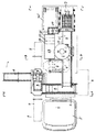
【図1】本発明の残土リサイクル処理プラントを示す側面図である。
【図2】作業状態の平面図である。
【図3】図2A−A線による正面図である。
【図4】図2B−B線による正面図である。
【図5】図2C−C線による背面図である。
【図6】上記プラントをトラック荷台上に前後逆に搭載した状態の側面図である。
【符号の説明】
1 トラック
2 荷台
3 主コンベヤ
4 混合機
5 ロールスクリーン
6 石灰粉供給機
7 混合物コンベヤ
8 混合物スクリーン
9 篩下搬出コンベヤ[0001]
BACKGROUND OF THE INVENTION
The present invention relates to a plant that manufactures improved soil from the excavated soil and recycles it as a backfill material in order to reuse a large amount of excavated soil generated in public works.
[0002]
[Prior art]
Conventionally, a large amount of excavated soil generated by public works has been accumulated in a stock yard, and this is reclaimed at a large plant on the ground and reprocessed into improved soil such as backfill material.
[0003]
Therefore, it is difficult to establish a large plant in order to obtain the improved soil in a place where stock yards are dispersed in many places and a relatively small amount of excavated soil is accumulated. Water pipes, gas pipes, wiring ducts There is a problem that it is difficult to use for small-scale construction such as backfilling to buried trenches.
[0004]
[Problems to be solved by the invention]
The present invention is a excavated soil recycling process in which a relatively small amount of backfill material required for piping work such as roads can be easily regenerated from excavated soil in a small-scale stockyard and moved to the small-scale stockyard as needed. The purpose is to obtain a plant.
[0005]
In order to achieve the above object, the present invention provides a main conveyor in the front-rear direction on a loading platform such as a truck, with one end of the main conveyor facing the upper part of the mixer provided on the loading platform, and rolled above the other end of the main conveyor. A screen is provided, a lime powder feeder is provided in the middle upper part, and a mixture forward / reverse conveyor is provided on the lower carrier of the mixer so that the mixture can be conveyed to the right or left of the carrier. The mixture screen supported by the lower ground at the front end of the forward / reverse conveyor of the mixture and the screen unloading conveyor of the screen can be detachably mounted on the loading platform. The excavated soil recycling treatment plant is constructed so that it can be directed backward, obliquely and backward .
[0006]
DETAILED DESCRIPTION OF THE INVENTION
In the present invention, the
[0007]
In this state, when the excavated soil mass is put on the roll screen 5, the excavated soil mass is broken by the rotation of the roll 5 ′ and the flange 5 ″ of the roll screen 5 (for example, 100 mm sieve mesh), and the mass is broken under the sieve of 100 mm or less. 3 falls on the sieve such as a cobblestone and rolls in the direction of inclination (backward) of the roll screen 5 and falls from the
[0008]
The sieving soil block or soil contains some water and swells with air during excavation and is conveyed forward by the
[0009]
The sieving unloading
[0010]
The sieves deposited as described above are loaded onto a carry-out truck, transported to a public construction site such as a gas pipe burying work, and reused as a backfill material.
[0011]
Thereafter, the
[0012]
【Example】
A
[0013]
A
[0014]
A rear inclined roll screen 5 is fixed to the
[0015]
A lime powder feeder 6 is fixed to the middle upper part of the
[0016]
Further, as shown by phantom lines in FIG. 1, the
[0017]
The lime powder is continuously supplied in a fixed amount from the lime powder supply machine 6 to the water-containing excavated mass or soil on the main conveyor 3 (the determination can be appropriately set), and further supplied to the
[0018]
Conversely, a
[0019]
In the figure,
[0020]
【The invention's effect】
Since the present invention is configured as described above, there is an effect that it can be moved to a small-scale stock yard of excavated soil generated by public works as needed, and the sedimentary excavated soil can be easily regenerated into improved soil.
[Brief description of the drawings]
FIG. 1 is a side view showing a residual soil recycling treatment plant of the present invention.
FIG. 2 is a plan view of a working state.
FIG. 3 is a front view taken along line 2A-A in FIG.
FIG. 4 is a front view taken along line B-B in FIG.
5 is a rear view taken along line 2C-C in FIG.
FIG. 6 is a side view showing a state where the plant is mounted on the truck bed in the reverse direction.
[Explanation of symbols]
1
Claims (1)
Priority Applications (1)
| Application Number | Priority Date | Filing Date | Title |
|---|---|---|---|
| JP30737797A JP3761696B2 (en) | 1997-11-10 | 1997-11-10 | Excavated soil recycling plant |
Applications Claiming Priority (1)
| Application Number | Priority Date | Filing Date | Title |
|---|---|---|---|
| JP30737797A JP3761696B2 (en) | 1997-11-10 | 1997-11-10 | Excavated soil recycling plant |
Publications (2)
| Publication Number | Publication Date |
|---|---|
| JPH11140904A JPH11140904A (en) | 1999-05-25 |
| JP3761696B2 true JP3761696B2 (en) | 2006-03-29 |
Family
ID=17968332
Family Applications (1)
| Application Number | Title | Priority Date | Filing Date |
|---|---|---|---|
| JP30737797A Expired - Lifetime JP3761696B2 (en) | 1997-11-10 | 1997-11-10 | Excavated soil recycling plant |
Country Status (1)
| Country | Link |
|---|---|
| JP (1) | JP3761696B2 (en) |
Families Citing this family (3)
| Publication number | Priority date | Publication date | Assignee | Title |
|---|---|---|---|---|
| FR2800729B1 (en) * | 1999-11-05 | 2001-12-07 | Traitement Valorisation Decont | MOBILE PLANT FOR TREATING CONTAMINATED SLUDGE OR SOIL FOR THE ERADICATION OF PATHOGENS BY LIVE LIME TREATMENT |
| JP2002212972A (en) * | 2001-01-19 | 2002-07-31 | Sumitomo (Shi) Construction Machinery Manufacturing Co Ltd | Mobile working machine for civil engineering and construction |
| GB2478150A (en) * | 2010-02-26 | 2011-08-31 | Yorkshire Water Services Ltd | A material recycling apparatus for processing trench arisings |
-
1997
- 1997-11-10 JP JP30737797A patent/JP3761696B2/en not_active Expired - Lifetime
Also Published As
| Publication number | Publication date |
|---|---|
| JPH11140904A (en) | 1999-05-25 |
Similar Documents
| Publication | Publication Date | Title |
|---|---|---|
| JP2867235B2 (en) | Self-propelled soil improvement machine | |
| US6530723B2 (en) | Device and process for excavating and backfilling of soil | |
| JP3761696B2 (en) | Excavated soil recycling plant | |
| JP2019157502A (en) | Roadbed construction method | |
| JPH08206537A (en) | Self-traveling type surplus soil regenerating car | |
| JPH0796210A (en) | Self-traveling crushing screening device | |
| JP3244152B2 (en) | On-board generated soil improvement device | |
| JPH089232Y2 (en) | Vehicles equipped with soil recycling equipment | |
| JP3338389B2 (en) | Self-propelled soil improvement machine | |
| JP3738215B2 (en) | Self-propelled soil improvement machine | |
| JP5158628B2 (en) | Tunnel excavation soil treatment equipment | |
| JPH0237849Y2 (en) | ||
| JP3830231B2 (en) | Soil improvement plant vehicle capable of traveling on the road and soil improvement method using the same | |
| JP2008018384A (en) | Insolubilization treatment apparatus | |
| JP2002339397A (en) | Automotive mud hardening apparatus | |
| JP2001049693A (en) | Excavated soil recycling plant | |
| JP2001079442A (en) | Work vehicle | |
| JP2001049692A (en) | Method and device for improving excavated soil | |
| JP3375600B2 (en) | Soil improvement method | |
| JPH0431325Y2 (en) | ||
| JP2003176546A (en) | Soil improvement system and self-propelled sorting machine used for the same | |
| JP2003321850A (en) | Self propelling powdery and granular material feeder and earth and sand mixing system using the same | |
| JP4398614B2 (en) | Self-propelled soil improvement machine | |
| JP2009108583A (en) | Method for utilizing tunnel excavated soil | |
| JPH10317425A (en) | Transferable excavated-soil improving device, and method and device for back-filling the soil at construction site |
Legal Events
| Date | Code | Title | Description |
|---|---|---|---|
| A621 | Written request for application examination |
Free format text: JAPANESE INTERMEDIATE CODE: A621 Effective date: 20040409 |
|
| A521 | Written amendment |
Free format text: JAPANESE INTERMEDIATE CODE: A821 Effective date: 20040528 |
|
| RD02 | Notification of acceptance of power of attorney |
Free format text: JAPANESE INTERMEDIATE CODE: A7422 Effective date: 20040528 |
|
| A521 | Written amendment |
Free format text: JAPANESE INTERMEDIATE CODE: A523 Effective date: 20040519 |
|
| A521 | Written amendment |
Free format text: JAPANESE INTERMEDIATE CODE: A821 Effective date: 20040528 |
|
| A131 | Notification of reasons for refusal |
Free format text: JAPANESE INTERMEDIATE CODE: A131 Effective date: 20050913 |
|
| A521 | Written amendment |
Free format text: JAPANESE INTERMEDIATE CODE: A523 Effective date: 20051110 |
|
| TRDD | Decision of grant or rejection written | ||
| A01 | Written decision to grant a patent or to grant a registration (utility model) |
Free format text: JAPANESE INTERMEDIATE CODE: A01 Effective date: 20051213 |
|
| A61 | First payment of annual fees (during grant procedure) |
Free format text: JAPANESE INTERMEDIATE CODE: A61 Effective date: 20060111 |
|
| R150 | Certificate of patent or registration of utility model |
Free format text: JAPANESE INTERMEDIATE CODE: R150 |
|
| FPAY | Renewal fee payment (event date is renewal date of database) |
Free format text: PAYMENT UNTIL: 20100120 Year of fee payment: 4 |
|
| FPAY | Renewal fee payment (event date is renewal date of database) |
Free format text: PAYMENT UNTIL: 20100120 Year of fee payment: 4 |
|
| S111 | Request for change of ownership or part of ownership |
Free format text: JAPANESE INTERMEDIATE CODE: R313111 |
|
| FPAY | Renewal fee payment (event date is renewal date of database) |
Free format text: PAYMENT UNTIL: 20100120 Year of fee payment: 4 |
|
| R371 | Transfer withdrawn |
Free format text: JAPANESE INTERMEDIATE CODE: R371 |
|
| FPAY | Renewal fee payment (event date is renewal date of database) |
Free format text: PAYMENT UNTIL: 20100120 Year of fee payment: 4 |
|
| S111 | Request for change of ownership or part of ownership |
Free format text: JAPANESE INTERMEDIATE CODE: R313115 |
|
| FPAY | Renewal fee payment (event date is renewal date of database) |
Free format text: PAYMENT UNTIL: 20100120 Year of fee payment: 4 |
|
| R350 | Written notification of registration of transfer |
Free format text: JAPANESE INTERMEDIATE CODE: R350 |
|
| FPAY | Renewal fee payment (event date is renewal date of database) |
Free format text: PAYMENT UNTIL: 20100120 Year of fee payment: 4 |
|
| FPAY | Renewal fee payment (event date is renewal date of database) |
Free format text: PAYMENT UNTIL: 20110120 Year of fee payment: 5 |
|
| FPAY | Renewal fee payment (event date is renewal date of database) |
Free format text: PAYMENT UNTIL: 20110120 Year of fee payment: 5 |
|
| FPAY | Renewal fee payment (event date is renewal date of database) |
Free format text: PAYMENT UNTIL: 20120120 Year of fee payment: 6 |
|
| S111 | Request for change of ownership or part of ownership |
Free format text: JAPANESE INTERMEDIATE CODE: R313117 |
|
| FPAY | Renewal fee payment (event date is renewal date of database) |
Free format text: PAYMENT UNTIL: 20130120 Year of fee payment: 7 |
|
| FPAY | Renewal fee payment (event date is renewal date of database) |
Free format text: PAYMENT UNTIL: 20130120 Year of fee payment: 7 |
|
| R350 | Written notification of registration of transfer |
Free format text: JAPANESE INTERMEDIATE CODE: R350 |
|
| FPAY | Renewal fee payment (event date is renewal date of database) |
Free format text: PAYMENT UNTIL: 20140120 Year of fee payment: 8 |
|
| R250 | Receipt of annual fees |
Free format text: JAPANESE INTERMEDIATE CODE: R250 |
|
| R250 | Receipt of annual fees |
Free format text: JAPANESE INTERMEDIATE CODE: R250 |
|
| R250 | Receipt of annual fees |
Free format text: JAPANESE INTERMEDIATE CODE: R250 |
|
| R250 | Receipt of annual fees |
Free format text: JAPANESE INTERMEDIATE CODE: R250 |
|
| EXPY | Cancellation because of completion of term |