JP3761237B2 - Air bag case - Google Patents
Air bag case Download PDFInfo
- Publication number
- JP3761237B2 JP3761237B2 JP00662896A JP662896A JP3761237B2 JP 3761237 B2 JP3761237 B2 JP 3761237B2 JP 00662896 A JP00662896 A JP 00662896A JP 662896 A JP662896 A JP 662896A JP 3761237 B2 JP3761237 B2 JP 3761237B2
- Authority
- JP
- Japan
- Prior art keywords
- airbag
- case
- retainer
- holes
- case body
- Prior art date
- Legal status (The legal status is an assumption and is not a legal conclusion. Google has not performed a legal analysis and makes no representation as to the accuracy of the status listed.)
- Expired - Fee Related
Links
- 230000002093 peripheral effect Effects 0.000 claims description 61
- 210000000078 claw Anatomy 0.000 claims description 43
- 238000005452 bending Methods 0.000 claims description 10
- 238000004519 manufacturing process Methods 0.000 description 5
- 239000000463 material Substances 0.000 description 5
- 239000002184 metal Substances 0.000 description 4
- 230000000149 penetrating effect Effects 0.000 description 4
- 238000009434 installation Methods 0.000 description 3
- 238000010008 shearing Methods 0.000 description 3
- 230000000694 effects Effects 0.000 description 2
- 229920003002 synthetic resin Polymers 0.000 description 2
- 239000000057 synthetic resin Substances 0.000 description 2
- 238000010586 diagram Methods 0.000 description 1
- 238000005553 drilling Methods 0.000 description 1
- 238000000605 extraction Methods 0.000 description 1
- 238000012986 modification Methods 0.000 description 1
- 230000004048 modification Effects 0.000 description 1
- 238000000926 separation method Methods 0.000 description 1
- 238000003466 welding Methods 0.000 description 1
Images


Landscapes
- Air Bags (AREA)
Description
【0001】
【発明の属する技術分野】
本発明は、エアバッグを収納して車両のインストルメントパネル等に配設されるエアバッグケースの改良に関するものである。
【0002】
【従来の技術】
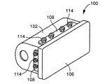
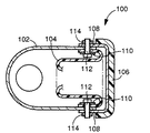
車両の衝突時における車室内の乗員保護のため、インストルメントパネル等にエアバッグを装着することが広く行われている。このエアバッグは一般にエアバッグケース内に収納されて車両に装着され、車両衝突時にガス発生器からガスが発生させられることによりエアバッグケースから膨出させられるようになっている。図21および図22に示すエアバッグケース100はその一例で、容器状のケース本体102の開口周縁部の内側にエアバッグ104の開口周縁部が固定された状態で、そのケース本体102内にエアバッグ104を収納するようになっている。また、このエアバッグケース100は、エアバッグ104を収納した状態でケース本体102の開口部を覆蓋するドア106を備えており、ドア106の取付部108がケース本体102の開口周縁部の外側に固定されている。ケース本体102の開口部は長方形状を成しており、取付部108はその長方形の4辺に分離して設けられている。
【0003】
上記ケース本体102の開口周縁部、エアバッグ104の開口周縁部、およびドア106の取付部108には、各辺毎にそれぞれ複数の貫通孔が形成されている一方、エアバッグ104の開口周縁部の内側に配設されるリテーナ110には複数のボルト112が固設されており、それ等のボルト112がエアバッグ104、ケース本体102、および取付部108の貫通孔を貫通させられ、取付部108の外側からナット114が螺合されることにより、それ等が一体的に固定されるようになっている。リテーナ110は、ケース本体102の開口部の4辺に対応して4つに分割して用意される。図23は、上辺または下辺に用いられるリテーナ110で、この例では4個のボルト112が固設されている。
【0004】
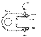
また、図24のエアバッグケース120はドアなしタイプで、上記のようにボルトおよびナットによって固定することもできるが、この例では、長手形状のリテーナ122に固設されたリベット124がエアバッグ104およびケース本体102の貫通孔を貫通させられた状態でかしめられることにより、それ等を一体的に固定するようになっている。
【0005】
【発明が解決しようとする課題】
しかしながら、このように複数のボルトに一つ一つナットを螺合したり、複数のリベットを一つ一つかしめたりする作業は時間がかかるという問題があった。
【0006】
本発明は以上の事情を背景として為されたもので、その目的とするところは、ナットやリベットを用いることなくエアバッグやドアをケース本体に簡単に組み付けられるようにすることにある。
【0007】
【課題を解決するための手段】
かかる目的を達成するために、第1発明は、容器状のケース本体の開口周縁部にエアバッグの開口周縁部が固定された状態で、そのケース本体内にそのエアバッグを収納するエアバッグケースであって、(a) 前記ケース本体の開口周縁部および前記エアバッグの開口周縁部にはそれぞれ複数の貫通孔が設けられている一方、(b) その複数の貫通孔に跨がって位置するように長手形状を成し、互いに重ね合わされた前記ケース本体および前記エアバッグの開口周縁部の内側または外側に配設されるとともに、そのケース本体およびエアバッグの貫通孔を共に貫通して反対側まで突き出す複数の係止部が一体に設けられたバッグリテーナと、(c) そのバッグリテーナと略同じ長さ寸法を有して前記反対側に配設されるとともに、そのバッグリテーナの前記複数の係止部に係止されることにより、そのバッグリテーナとの間でそのケース本体およびエアバッグの開口周縁部を一体的に固定する固定部材とを有し、且つ、 (d) 前記バッグリテーナは、前記複数の貫通孔に跨がって位置するように長手形状を成す本体部と前記複数の係止部とを有するもので、その係止部は、その本体部の長手方向と略直角な方向へその本体部から突き出す突出部と、その突出部の先端においてその突出部の突き出し方向と略直角な方向へ突き出す係合頭部とを有するものである一方、 (e) 前記固定部材は、前記係合頭部と係合させられる爪部を長手方向に離間して複数備え、その複数の爪部がその複数の係合頭部にそれぞれ略同じタイミングで係合させられて前記係止部に係止されるものであることを特徴とする。
【0008】
第2発明は、容器状のケース本体の開口周縁部にエアバッグの開口周縁部が固定された状態で、そのケース本体内にそのエアバッグを収納するエアバッグケースであって、(a) 前記ケース本体の開口周縁部および前記エアバッグの開口周縁部にはそれぞれ複数の貫通孔が設けられている一方、(b) その複数の貫通孔に跨がって位置するように長手形状を成し、互いに重ね合わされた前記ケース本体および前記エアバッグの開口周縁部の内側または外側に配設されるとともに、そのケース本体およびエアバッグの貫通孔を共に貫通して反対側まで突き出す複数の係止部が一体に設けられたバッグリテーナと、(c) そのバッグリテーナと略同じ長さ寸法を有して前記反対側に配設されるとともに、そのバッグリテーナの前記複数の係止部に係止されることにより、そのバッグリテーナとの間でそのケース本体およびエアバッグの開口周縁部を一体的に固定する固定部材とを有し、且つ (d) 前記バッグリテーナは、前記複数の貫通孔に跨がって位置する長手形状の板状部材にて構成され、前記複数の係止部は、それぞれその板状部材の一部がその板状部材の長手方向と略直角な折曲線に沿って略直角に曲げ起こされたもので、その曲げ起こされた複数の係止部にはそれぞれ貫通した係止穴が形成されている一方、 (e) 前記固定部材は棒状の部材で、前記板状部材の長手方向に離間して設けられた前記複数の係止部の前記係止穴内に一端から順番に挿通させられて、その複数の係止部に係止されるものであることを特徴とする。
【0009】
第3発明は、容器状のケース本体の開口周縁部内側にエアバッグの開口周縁部が固定された状態で、そのケース本体内にそのエアバッグを収納するとともに、そのエアバッグを収納した状態でそのケース本体の開口部を覆蓋するドアの取付部が該ケース本体の開口周縁部外側に固定されるエアバッグケースであって、(a) 前記ケース本体の開口周縁部、前記エアバッグの開口周縁部、および前記ドアの取付部にはそれぞれ複数の貫通孔が設けられている一方、(b) その複数の貫通孔に跨がって位置するように長手形状を成し、前記エアバッグの開口周縁部の内側に配設されるとともに、そのエアバッグおよび前記ケース本体の貫通孔を共に貫通してそのケース本体の外側まで突き出す複数の係止部が一体に設けられたバッグリテーナと、(c) そのバッグリテーナと略同じ長さ寸法を有して前記ドアの取付部の外側に配設されるとともに、その取付部の貫通孔を貫通させられる複数の係止部が一体的に設けられたドアリテーナと、(d) 前記バッグリテーナおよび前記ドアリテーナと略同じ長さ寸法を有して前記ケース本体と前記ドアの取付部との間に配設されるとともに、そのバッグリテーナおよびドアリテーナの双方の複数の係止部に係止され、そのバッグリテーナおよびドアリテーナをケース本体に離脱不能に固定する固定部材とを有することを特徴とする。
【0010】
第4発明は、容器状のケース本体の開口周縁部内側にエアバッグの開口周縁部が固定された状態で、そのケース本体内にそのエアバッグを収納するとともに、そのエアバッグを収納した状態でそのケース本体の開口部を覆蓋するドアの取付部がそのケース本体の開口周縁部外側に固定されるエアバッグケースであって、(a) 前記ケース本体の開口周縁部、前記エアバッグの開口周縁部、および前記ドアの取付部にはそれぞれ複数の貫通孔が設けられている一方、(b) その複数の貫通孔に跨がって位置するように長手形状を成し、前記エアバッグの開口周縁部の内側に配設されるとともに、そのエアバッグおよび前記ケース本体の貫通孔を共に貫通してそのケース本体の外側まで突き出す複数の門型の係止部が一体に設けられたバッグリテーナと、(c) そのバッグリテーナと略同じ長さ寸法を有して前記ドアの取付部の外側に配設されるとともに、その取付部の貫通孔を貫通させられる複数の門型の係止部が一体的に設けられたドアリテーナと、(c) 前記バッグリテーナおよび前記ドアリテーナと略同じ長さ寸法を有して前記ケース本体と前記ドアの取付部との間に配設されるとともに、そのバッグリテーナおよびドアリテーナの双方の複数の係止部の内側を挿通させられ、そのバッグリテーナおよびドアリテーナをそのケース本体に離脱不能に固定する固定部材とを有することを特徴とする。
【0011】
第5発明は、前記第3発明のエアバッグケースにおいて、(a) 前記バッグリテーナは、前記複数の貫通孔に跨がって位置するように長手形状を成す本体部と前記複数の係止部とを有するもので、その係止部は、その本体部の長手方向と略直角な方向へその本体部から突き出す突出部と、その突出部の先端においてその突出部の突き出し方向と略直角な方向へ突き出す係合頭部とを有するものである一方、(b) 前記固定部材は、前記係合頭部と係合させられる爪部を長手方向に離間して複数備え、その複数の爪部が複数の係合頭部にそれぞれ略同じタイミングで係合させられて前記係止部に係止されるものであることを特徴とする。
【0012】
第6発明は、前記第3発明のエアバッグケースにおいて、(a) 前記バッグリテーナは、前記複数の貫通孔に跨がって位置する長手形状の板状部材にて構成され、前記複数の係止部は、それぞれその板状部材の一部がその板状部材の長手方向と略直角な折曲線に沿って略直角に曲げ起こされたもので、その曲げ起こされた複数の係止部にはそれぞれ貫通した係止穴が形成されている一方、(b) 前記固定部材は棒状の部材で、前記板状部材の長手方向に離間して設けられた前記複数の係止部の前記係止穴内に一端から順番に挿通させられて、その複数の係止部に係止されるものであることを特徴とする。
【0013】
第7発明は、容器状のケース本体の開口周縁部内側にエアバッグの開口周縁部が固定された状態で、そのケース本体内にそのエアバッグを収納するエアバッグケースであって、(a) 前記ケース本体の開口周縁部および前記エアバッグの開口周縁部にはそれぞれ複数の貫通孔が設けられている一方、(b) その複数の貫通孔に跨がって位置する長手形状の板状部材にて構成されているとともに、その板状部材の一部が略直角に曲げ起こされることによりT字形または逆L字形の複数の係止部が設けられ、前記エアバッグの開口周縁部の内側に配設されるとともにその複数の係止部がそれぞれそのエアバッグおよび前記ケース本体の貫通孔を共に貫通してそのケース本体の外側まで突き出すバッグリテーナを有し、(c) そのバッグリテーナは、前記係止部のうち前記ケース本体の外側まで突き出している前記T字形または逆L字形の横棒部分が、そのケース本体からの突き出し方向と略平行な折曲線に沿って折り曲げられることにより、そのケース本体に離脱不能に固定されていることを特徴とする。
【0014】
【発明の効果】
第1発明および第2発明においては、それぞれ複数の貫通孔が設けられたケース本体およびエアバッグの開口周縁部の内側または外側に、それ等複数の貫通孔に跨がって位置する長手形状のバッグリテーナを配設し、そのバッグリテーナに設けられた複数の係止部をそれぞれ複数の貫通孔内に挿入して反対側まで突き出させ、その複数の係止部に固定部材を係止させれば良いため、部品点数が少なくて組付け作業を容易且つ迅速に行うことができるとともに製造コストが低減される。すなわち、第1発明では、複数の係止部に対応して複数の爪部が固定部材に設けられているため、各爪部が係止部に係合させられるように固定部材を組み付ければ良く、第2発明の係止部は、バッグリテーナの長手方向と略直角な折曲線に沿って曲げ起こされるとともに貫通した係止穴が設けられたものであるため、複数の係止部の係止穴内を挿通させるように棒状の固定部材を組み付ければ良い。
【0015】
一方、第1発明では、固定部材の長手方向に離間して複数の爪部が設けられ、それ等の爪部が複数の係合頭部にそれぞれ略同じタイミングで係合させられることにより、固定部材が係止部に係止されるようになっているため、一つの爪部を係合頭部に係合させるために必要なストローク分だけ固定部材を移動させることにより、総ての爪部を略同時に各係合頭部に係合させることができ、固定部材を容易且つ迅速に組み付けることができる。
第2発明では、バッグリテーナが長手形状の板状部材にて構成され、複数の係止部は、それぞれその板状部材の一部が長手方向と略直角な折曲線に沿って曲げ起こされたもので、その複数の係止部に設けられた係止穴に棒状の固定部材が一端から順番に挿通させられることにより、その固定部材が係止部に係止される。したがって、固定部材の組付け作業性は第1発明に比較して劣るが、バッグリテーナはプレス加工などによって容易且つ安価に製造できるとともに、固定部材は単純形状で複雑な加工が不要であるため、エアバッグケースの大幅なコストダウンを図ることができる。また、固定部材は係止穴を挿通させられるため、係止部が門型の場合と同様に高い機械的強度が得られ、肉厚や幅寸法などの各部の寸法を小さくしたり安価な材料を採用したりすることが可能で小型且つ安価に構成できる。
【0016】
第3発明はドアありタイプのエアバッグケースに関するもので、ドアの取付部の外側にもドアリテーナが配設され、ドアの取付部とケース本体との間に配設される固定部材がドアリテーナの係止部およびバッグリテーナの係止部の双方に係止されることにより、それ等のリテーナがケース本体に固定されるようになっているため、それ等の組付け作業を容易且つ迅速に行うことができる。また、固定部材や係止部がドアの取付部やドアリテーナの内側に隠れるため、バッグリテーナの係止部をドアの取付部の外側まで突き出させてその取付部の外側に固定部材を配設することによりドアリテーナを省略する場合や、従来のようにナットやリベットが露出している場合に比較してケースの外周形状が簡潔になる。
【0017】
第4発明は第3発明の一実施態様で、第3発明と同様の作用効果が得られるのに加え、バッグリテーナおよびドアリテーナに設けられる係止部は門型、すなわちコの字形状やU字形状などで両端が固定されているため、高い機械的強度が得られてボルト止めやリベット止めの代わりに用いることができるとともに、肉厚や幅寸法などの各部の寸法を小さくしたり安価な材料を採用したりすることが可能で小型且つ安価に構成できる。
【0018】
第5発明では、固定部材の長手方向に離間して複数の爪部が設けられ、それ等の爪部が複数の係合頭部にそれぞれ略同じタイミングで係合させられることにより、固定部材が係止部に係止されるようになっている。すなわち、一つの爪部を係合頭部に係合させるために必要なストローク分だけ固定部材を移動させることにより、総ての爪部を略同時に各係合頭部に係合させることができるのであり、固定部材を容易且つ迅速に組み付けることができる。
【0019】
第6発明では、バッグリテーナが長手形状の板状部材にて構成され、複数の係止部は、それぞれその板状部材の一部が長手方向と略直角な折曲線に沿って曲げ起こされたもので、その複数の係止部に設けられた係止穴に棒状の固定部材が一端から順番に挿通させられることにより、その固定部材が係止部に係止される。したがって、固定部材の組付け作業性は第5発明に比較して劣るが、バッグリテーナはプレス加工などによって容易且つ安価に製造できるとともに、固定部材は単純形状で複雑な加工が不要であるため、エアバッグケースの大幅なコストダウンを図ることができる。また、固定部材は係止穴を挿通させられるため、係止部が門型の場合と同様に高い機械的強度が得られ、肉厚や幅寸法などの各部の寸法を小さくしたり安価な材料を採用したりすることが可能で小型且つ安価に構成できる。
【0020】
第7発明では、バッグリテーナが長手形状の板状部材にて構成され、その板状部材の一部が略直角に曲げ起こされることによりT字形または逆L字形の複数の係止部が設けられているとともに、それ等の係止部がそれぞれエアバッグおよびケース本体の貫通孔を共に貫通してケース本体の外側まで突き出され、且つT字形または逆L字形の横棒部分がケース本体からの突き出し方向と略平行な折曲線に沿って折り曲げられることにより、バッグリテーナとケース本体との間でエアバッグの開口周縁部を固定した状態でバッグリテーナがケース本体に離脱不能に固定される。すなわち、本発明では他の発明のような固定部材が不要であるとともに、バッグリテーナはプレス加工などによって容易且つ安価に製造できるため、エアバッグケースの大幅なコストダウンを図ることができる。また、係止部は、T字形または逆L字形の横棒部分がケース本体からの突き出し方向と略平行な折曲線に沿って折り曲げられるようになっているため、高い機械的強度が得られるとともに、従来のリベット止めのようにかしめ加工する場合に比較して作業を容易且つ迅速に行うことができる。
【0021】
【発明の実施の形態】
ここで、上記バッグリテーナや固定部材、ドアリテーナは、それぞれケース本体の開口部の形状に倣って変形可能な単一の部材にて構成することも可能であるが、ケース本体の開口部が複数の直線状部分から成る角形状を成している場合は、その直線状部分すなわち各辺毎に分割された直線状の複数の部材にて構成することが望ましい。すなわち、ケース本体の開口部が長方形などの角形状を成している場合には、そのケース本体の開口周縁部、エアバッグの開口周縁部、ドアの取付部の各辺毎にそれぞれ複数の貫通孔を形成し、その各辺毎にバッグリテーナ、ドアリテーナ、固定部材を用いて固定するのである。但し、一つの辺を複数に分割し、それぞれ本発明に従って固定するようにしても良いし、ケース本体の開口部の全周が本発明に従って固定される必要はなく、一つの辺など一部が本発明に従って固定されるようになっているだけでも良い。特に、ドアについては必ずしも全周をケース本体に固定する必要はなく、一つの辺など一部をケース本体に固定するだけでも良い。
【0022】
第1発明および第2発明では、エアバッグの開口周縁部を他の発明と同様にケース本体とバッグリテーナとの間で挟むようにしても良いが、固定部材はバッグリテーナと略同じ長さ寸法を有しているため、ケース本体と固定部材との間でエアバッグの開口周縁部を挟むようにすることもできる。また、エアバッグの開口周縁部をケース本体の開口周縁部の外側に重ね合わせるようにしても良いし、バッグリテーナをケース本体の外側に配設して固定部材を内側に配設することもできる。
【0023】
第4発明における固定部材は、例えば第6発明のように単純な長手状の部材で複数の係止部の一端から他端まで順番に挿通させられるものでも良いが、長手状の本体部に係止部に対応して複数の爪部が設けられ、その複数の爪部がそれぞれ係止部を挿通させられるように構成することもできる。その場合は、一つの係止部に相当する長さだけ固定部材を動かすだけで複数の係止部にそれぞれ爪部を挿通させることができるため、組付け作業が一層容易となる。
【0024】
第3発明および第4発明では、ドアの取付部の外側にもドアリテーナが配設され、ドアの取付部とケース本体との間に配設される固定部材がドアリテーナの係止部およびバッグリテーナの係止部の双方に係止されるようになっているが、他の発明の実施に際してはバッグリテーナの係止部をドアの取付部の外側まで突き出させ、その取付部の外側に固定部材を配設するか、第7発明の場合には取付部の外側で係止部の先端を曲げ加工することにより、ドアリテーナを省略することが可能である。なお、これ等の第3発明および第4発明以外の発明、すなわち第1発明、第2発明、第5発明〜第7発明が、ドアなしのエアバッグケースにも適用され得ることは勿論である。
【0025】
また、第3発明および第4発明では、バッグリテーナの係止部およびドアリテーナの係止部が共通の固定部材と係合させられるが、それ等の係止部の位置は互いに近接していることが望ましく、ケース本体、エアバッグ、およびドアの取付部には、両係止部が隣接する状態で挿入され得る大きさの貫通孔を同じ位置に形成することが望ましい。また、共通の固定部材に係合させられる両リテーナの係止部の高さ寸法が同じとなるように、ケース本体およびエアバッグの肉厚に応じてドアの取付部の肉厚を設定すれば、両リテーナの共通化を図ることができて部品管理や組付け作業が一層容易となる。
【0026】
第5発明のバッグリテーナは、例えば複数の貫通孔に跨がって位置する長手形状の板状部材にて構成されるとともに、複数の係止部は、その板状部材の一部が略直角に曲げ起こされたT字形または逆L字形の曲げ起こし部分にて構成され、その場合には、プレス加工などによって容易且つ安価に製造できるため、エアバッグケースのコストダウンを図ることができる。曲げ起こされた係止部以外の部分が本体部で、T字形または逆L字形の縦棒部分は突出部に相当し、横棒部分は係合頭部に相当する。上記曲げ起こし部分の折曲線の向きは任意に定められるが、板状部材の長手方向と平行か或いはその長手方向と直角であることが望ましい。なお、小径円柱形状の突出部と大径円柱形状の係合頭部とを一体に有するピンを係止部として用意し、長手形状の板状部材などに立設するなど、本発明の係止部は種々の手段で構成できる。
【0027】
また、第5発明における固定部材の爪部は、例えば隙間寸法が前記係合頭部の幅寸法より小さい一対の係合爪を有し、それ等の係合爪と係合頭部との係合によって係止部からの抜出しが阻止されるように構成される。一対の係合爪の隙間寸法は、係合爪自身が弾性変形可能であれば突出部より小さくても差し支えなく、その場合はその弾性力によって係止部との係合状態が良好に維持される。
【0028】
次に、本発明の実施例を図面に基づいて詳細に説明する。
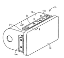
図1は、第3発明、第4発明の一実施例であるエアバッグケース10の斜視図で、図2は図1におけるII−II断面図、図3は図1における III− III断面図、図4はエアバッグケース10の主要な部材の組付け前の状態を示す分解図である。このエアバッグケース10は、例えば自動車の助手席前方のインストルメントパネルに装着されるもので、上下方向の断面が略U字形状を成すとともに開口部が長方形状を成している容器状のケース本体12内には、合成樹脂等から成る袋状のエアバッグ14が収納されているとともに、ケース本体12の開口部は合成樹脂製のドア16によって覆蓋されている。
【0029】
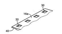
エアバッグ14は、前記図22,図24の場合と同様に、その開口部がケース本体12の開口部に対向する姿勢で開口周縁部がケース本体12の開口周縁部の内側に取り付けられ、折り畳んだり巻き込んだりした状態でケース本体12内に収納されており、ケース本体12内に配設されたガス発生器から車両衝突時に所定のガスが発生させられることにより、ケース本体12の開口部から外部に膨出させられる。また、ドア16は、ケース本体12の開口部に対応する長方形状を成しているとともに、各辺毎に取付部16aが一体的に設けられてケース本体12の4つの側壁の外側にそれぞれ固定されている一方、上記エアバッグ14の膨張時には前面の一部が切り開かれてエアバッグ14がケース本体12から膨出することを許容するようになっている。
【0030】
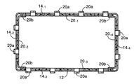
上記エアバッグ14およびドア16の取付部16aは、ケース本体12の4つの側壁毎にバッグリテーナ20、ドアリテーナ22、および固定部材24によってケース本体12に固定されるようになっている。ケース本体12の開口周縁部のうち上側に位置する上部側壁、すなわち図1および図4における上側の側壁部分の組付構造について具体的に説明すると、その上部側壁には開口端縁に沿って4つの貫通孔26が形成されているとともに、エアバッグ14の開口周縁部のうち上記上部側壁に取り付けられる部分、およびドア16の4つの取付部16aのうち上部側壁に取り付けられるものには、それぞれ上記貫通孔26に対応して同じ位置に4つの貫通孔28、30が形成されている。図4に示されているバッグリテーナ20、ドアリテーナ22、および固定部材24は、この上部側壁に対する組付けに使用するものである。
【0031】
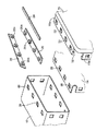
バッグリテーナ20はエアバッグ14の開口周縁部の内側に配設されるもので、上記4つの貫通孔26に跨がって位置するように上部側壁と略同じ長さ寸法を有する長手形状を成しているとともに、貫通孔28および26を共に貫通してケース本体12の外側まで突き出すように略コの字形状を成す門型の係止部20aが、各貫通孔28および26に対応して長手方向に離間して4個設けられている。ドアリテーナ22は取付部16aの外側に配設されるもので、上記バッグリテーナ20と同じ長さ寸法を有する長手形状を成しているとともに、貫通孔30を貫通するように略コの字形状を成す門型の係止部22aが、貫通孔30に対応して長手方向に離間して4個設けられている。これ等のバッグリテーナ20およびドアリテーナ22は板金製で、係止部20a,22aはせん断および絞りプレスによって形成されている。
【0032】
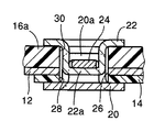
上記貫通孔26,28,30は何れも同じ大きさで略正方形状を成しているとともに、係止部20a,22aの幅寸法は貫通孔26,28,30の1辺の長さの1/2より小さく、図3から明らかなように、両係止部20a,22aは隣接する状態で同じ位置の貫通孔26,28,30内に挿入される。また、取付部16aの内側すなわちケース本体12側の面には、4つの貫通孔30と交差するように長手方向に1本の溝32が設けられており、上記のように係止部20a,22aが共に貫通孔26,28,30内に挿入された状態で、溝32の一方の開口部から棒状の固定部材24が挿入されると、その固定部材24は両係止部20a,22aの双方の内側、すなわち図2および図3では係止部20aの下側で係止部22aの上側を挿通させられ、バッグリテーナ20およびドアリテーナ22がケース本体12に離脱不能に固定される。係止部20a,22aはコの字形状を成して両端が固定されているため、十分な機械的強度が得られ、ケース本体12の上部側壁にエアバッグ14の開口部の1辺およびドア16の1つの取付部16aが一体的に固定される。ケース本体12の下部側壁および左右の側壁にも、同様にしてエアバッグ14の開口部の各辺およびドア16の他の取付部16aが固定されるようになっており、これ等の4か所の組付形態は何れも本発明の一実施例に相当する。なお、左右の側壁の長さ寸法は短いため、貫通孔や係止部の数は2個である。
【0033】
上記取付部16aの肉厚は、両リテーナ20,22の係止部20a,22aの高さ寸法が同じとなるように、ケース本体12およびエアバッグ14の肉厚に応じて設定されている。具体的には、図3に示されているように溝32が形成された部分の取付部16aの肉厚が、ケース本体12の肉厚およびエアバッグ14の肉厚の合計値と略同じにされているのである。また、両係止部20a,22aは、共通の貫通孔26,28,30内に挿入されることから、その離間距離は互いに等しく、バッグリテーナ20およびドアリテーナ22は全く同じものが用いられる。
【0034】
また、かかるエアバッグケース10の組付けに際しては、先ずバッグリテーナ20によってエアバッグ14をケース本体12に組み付けた後、ドアリテーナ22によってドア16の取付部16aをケース本体12に組み付け、その後固定部材24を挿入してそれ等を離脱不能に固定すれば良い。図5はドア16を組み付ける前の状態、すなわち4つのバッグリテーナ20-1〜20-4によりエアバッグ14の4つの辺14-1〜14-4をそれぞれケース本体12に取り付けた状態を示す断面図であるが、左右のバッグリテーナ20-2および20-4の両端部には係合部20bが設けられ、それぞれ上下のバッグリテーナ20-1および20-3の端部と弾性的に係合させられるようになっている。これにより、これ等のバッグリテーナ20-1〜20-4のケース本体12に対する装着状態が良好に維持され、例えばケース本体12の外側に取付部16aを配置したりドアリテーナ22を装着したりする際に、バッグリテーナ20-1〜20-4がケース本体12から離脱することが防止される。上下のバッグリテーナ20-1および20-3の端部に係合部を設けることもできる。なお、上部のバッグリテーナ20-1は、前記図2〜図4におけるバッグリテーナ20に相当する。
【0035】
ここで、本実施例のエアバッグケース10は、エアバッグ14の内側にバッグリテーナ20を配設するとともにドア16の取付部16aの外側にドアリテーナ22を配設し、取付部16aとケース本体12との間に配設される固定部材24がバッグリテーナ20の係止部20aおよびドアリテーナ22の係止部22aの双方を挿通させられることにより、それ等のリテーナ20,22がケース本体12に固定され、エアバッグ14およびドア16がケース本体12に一体的に取り付けられるようになっているため、ボルト止めやリベット止めに比較して部品点数が少なく、それ等の組付け作業を容易且つ迅速に行うことができるとともに製造コストが低減される。
【0036】
また、バッグリテーナ20およびドアリテーナ22には略コの字形状を成す門型の係止部20a,22aが設けられているため、高い機械的強度が得られてボルト止めやリベット止めの代わりに用いることができるとともに、肉厚や幅寸法などの各部の寸法を小さくしたり安価な材料を採用したりすることが可能で小型且つ安価に構成できる。特に、本実施例では係止部20a,22aがせん断および絞りプレスによって形成されているとともに、単純な棒状の固定部材24が用いられているため、製造コストが一層低減される。
【0037】
また、エアバッグ14の開口周縁部はバッグリテーナ20とケース本体12との間に位置させられるため、固定部材24を配設する際にエアバッグ14と接触することがなく、固定部材24の組付け作業が容易である。
【0038】
また、固定部材24や係止部20a,22aが取付部16aやドアリテーナ22の内側に隠れるため、バッグリテーナ20の係止部20aをドア16の取付部16aの外側まで突き出させてその取付部16aの外側に固定部材24を配設することによりドアリテーナ22を省略する場合や、従来のようにナットやリベットを使用する場合に比較して、エアバッグケース10の外周形状が簡潔になる。
【0039】
また、バッグリテーナ20およびドアリテーナ22は同じものであるため、部品の種類が少なくなって管理や組付け作業が一層容易になる。また、左右のバッグリテーナ20-2および20-4の両端部に設けられた係合部20bにより、上下左右の計4つのバッグリテーナ20のケース本体12に対する装着状態が良好に維持されるため、その後のドア16の組付け作業などが容易になる利点がある。
【0040】
なお、上記実施例では単純な棒状の固定部材24が用いられていたが、図6の(a) ,(b) に示すように長手状の本体部36a,38aに係止部20a,22aに対応して複数の爪部36b,38bが設けられ、その複数の爪部36b,38bがそれぞれ係止部20a,22aを挿通させられる固定部材36,38を採用することもできる。その場合は、一つの係止部20a,22aに相当する長さだけ固定部材36,38を長手方向へ動かすだけで複数箇所の係止部20a,22aにそれぞれ爪部36b,38bを挿通させることができるため、組付け作業が一層容易となる。(a) の固定部材36を用いる場合は、例えば図7に示す取付部16aのように前記溝32と同じ深さで切欠40を形成し、その切欠40とケース本体12との間に側方から固定部材36を挿入するようにすれば良い。また、前記貫通孔26,28,30と略同じ大きさの切欠穴38cが形成され、その切欠穴38内に係止部20aおよび22aが挿入される梯子形状の固定部材38を用いる場合は、上記切欠40や前記溝32を形成した部分と同じ肉厚で取付部16aを設け、その取付部16aとケース本体12との間に予め固定部材38を配置して、ドアリテーナ22を組み付けるようにすれば良い。溝32の溝幅を固定部材38の幅寸法と略同じにして、その溝32内に固定部材38を配置するようにしても良い。
【0041】
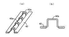
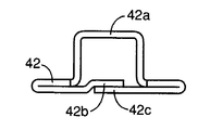
また、前記実施例のリテーナ20,22はプレスによる絞り加工で門型の係止部20a,22aが設けられていたが、図8に示すようにプレスによる抜き加工および曲げ加工によって複数の係止部42aを形成したリテーナ42を用いることもできる。その場合には、必要に応じて図9に示すように両端部42bおよび42cを重ね合わせ、スポット溶接などで一体的に固設することにより、十分な強度が得られるように補強しても良い。図8の(a) は斜視図で、(b) は端面図である。
【0042】
以上は請求項3、4に記載の発明の実施例であるが、次に他の発明の実施例を説明する。なお、以下の実施例において前記実施例と実質的に共通する部分には同一の符号を付して詳しい説明を省略する。また、以下の実施例は何れもドアなしタイプであるが、前記第1実施例のようなドアありタイプにも同様に適用できる。
【0043】
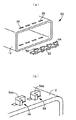
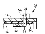
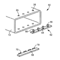
図10〜図12のエアバッグケース50は請求項7に記載の発明の一実施例で、図10の(a) は組付け前の状態におけるケース本体12および1本のバッグリテーナ52を示す斜視図であり、(b) は組み付けた後に係止部54の横棒部分54aが曲げ加工された状態を示す斜視図である。また、図11は縦断面図で、図12はバッグリテーナ52が配設された部分の拡大図である。
【0044】
バッグリテーナ52は、複数(実施例では4個)の貫通孔26に跨がって位置する長手形状の板状部材にて構成されているとともに、その側部に一体に設けられた複数(実施例では4個)のT字形状部が長手方向と平行な折曲線に沿ってそれぞれ略直角に曲げ起こされることにより、複数のT字形状の係止部54が設けられたもので、プレスによるブランキングおよび曲げ加工によって容易且つ安価に製造される。ケース本体12の貫通孔26およびエアバッグ14の貫通孔28は、何れも係止部54に対応して細長い溝形状を成しており、複数の係止部54がそれぞれそれ等の貫通孔28,26を共に貫通してケース本体12の外側まで突き出すとともに、そのケース本体12の外側まで突き出しているT字形状の横棒部分54aの一端部が、そのケース本体12からの突き出し方向と略平行な折曲線に沿って略90°折り曲げられることにより、バッグリテーナ52がケース本体12に離脱不能に固定されるとともにエアバッグ14の開口周縁部がケース本体12の開口周縁部に固定される。T字形状を成す係止部54の縦棒部分54bの長さ寸法は、ケース本体12の肉厚およびエアバッグ14の肉厚を加算した寸法と略同じである。
【0045】
なお、図11から明らかなように、エアバッグ14は、その開口部がケース本体12の開口部と同じ向きになる姿勢でケース本体12の内側に配設されているが、第1実施例と同様に反対向きに取り付けることも可能である。また、長方形状を成すケース本体12の開口周縁部のうち、比較的長い上下の側壁部のみにエアバッグ14が固定されるようになっているが、これは基本的な取付構造が同じであるため省略しただけで、第1実施例と同じように左右の側壁部にも同様にしてエアバッグ14の開口周縁部が固定される。これ等は、図13および図18の実施例についても同様である。
【0046】
かかる本実施例のエアバッグケース50においては、係止部54の横棒部分54aを折り曲げることによりバッグリテーナ52をケース本体12に離脱不能に固定するようになっているため、前記実施例における固定部材24が不要であるとともに、バッグリテーナ52はプレス加工によって容易且つ安価に製造されるため、エアバッグケース50の大幅なコストダウンを図ることができる。また、係止部54は、T字形状の横棒部分54aがケース本体12からの突き出し方向と略平行な折曲線に沿って折り曲げられるようになっているため、高い機械的強度が得られるとともに、従来のリベット止めのようにかしめ加工する場合に比較して作業を容易且つ迅速に行うことができる。
【0047】
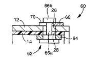
図13〜図15のエアバッグケース60は請求項1に記載の発明の一実施例で、図13は組付け前の状態におけるケース本体12、1本のバッグリテーナ62、および固定部材68を示す斜視図である。図14はバッグリテーナ62の断面図で、図15はバッグリテーナ62および固定部材68によりエアバッグ14がケース本体12に固定された部分の断面図である。図15は前記実施例の図12に対応する。
【0048】
バッグリテーナ62は、複数の貫通孔26に跨がって位置する長手形状の板状部材64と、その板状部材64に略垂直に立設された複数のピン66とから構成されている。板状部材64は本体部に相当し、ピン66は係止部に相当し、そのピン66は小径円柱形状の突出部66aと大径円柱形状の係合頭部66bとを一体に備えているとともに、板状部材64に圧入固定されている。前記ケース本体12の貫通孔26およびエアバッグ14の貫通孔28は、何れもピン66の係合頭部66bよりも大径の円穴で、ピン66がそれ等の貫通孔28,26を共に貫通してケース本体12の外側まで突き出すことを許容している。
【0049】
固定部材68は、バッグリテーナ62と略同じ長さ寸法を有する長手形状の板状部材で、その側部には爪部70が側方へ突き出すようにピン66に対応して長手方向に離間して4組設けられている。爪部70は一対の係合爪によって構成されており、その一対の係合爪の隙間寸法は、上記突出部66aの幅寸法と略同じで係合頭部66bの幅寸法より小さく、固定部材68が長手方向と直角な方向、すなわち爪部70の突き出し方向へ移動させられることにより、複数の爪部70の隙間内に複数の突出部66aがそれぞれ略同じタイミングで相対的に挿入され、これにより固定部材68がピン66に係止されるとともに、エアバッグ14の開口周縁部がケース本体12の開口周縁部に固定される。ピン66の突出部66aの長さ寸法は、ケース本体12の肉厚、エアバッグ14の肉厚、および固定部材68の板厚を加算した寸法と略同じであり、爪部70は例えば自身の弾性力によって突出部66aとの係合状態が維持されるとともに、係合頭部66bとの係合によってピン66からの抜出しが阻止される。また、上記固定部材68は、例えばプレスによるブランキング加工によって簡単且つ安価に製造される。
【0050】
本実施例のエアバッグケース60においても、エアバッグ14の開口周縁部の内側にバッグリテーナ62を配設し、そのバッグリテーナ62に設けられた複数のピン66をそれぞれ貫通孔28,26を貫通してケース本体12の外側まで突き出させ、その複数のピン66に固定部材68を係止させれば良いため、部品点数が少なくて組付け作業を容易且つ迅速に行うことができるとともに製造コストが低減される。
【0051】
また、固定部材68の複数の爪部70が複数のピン66にそれぞれ略同じタイミングで係合させられることにより、固定部材68がピン66に係止されるようになっているため、一つの爪部70をピン66に係合させるために必要なストローク分だけ固定部材68を移動させるだけで、総ての爪部70を略同時に各ピン66に係合させることができ、固定部材68を容易且つ迅速に組み付けることができる。更に、エアバッグ14の開口周縁部はバッグリテーナ62とケース本体12との間に位置させられるため、固定部材68を配設する際にエアバッグ14に直接触れることがなく、固定部材68の組付け作業が容易である。
【0052】
なお、前記図10〜図12の実施例においても、上記固定部材68と同様にバッグリテーナ52と略同じ長さ寸法を有するとともに長手方向に離間して複数の爪部が設けられた固定部材を用いて、バッグリテーナ52をケース本体12に固定することが可能である。その場合は、前記係止部54の縦棒部分54bの長さ寸法を固定部材の板厚分だけ大きくするとともに、その縦棒部分54bの幅寸法に応じて爪部の隙間を設定することになる。
【0053】
また、上記実施例ではバッグリテーナ62がエアバッグ14の開口周縁部の内側に配設されているが、バッグリテーナ62をケース本体12の外側に配設して、ピン66をエアバッグ14の内側まで貫通させ、そのエアバッグ14の内側に固定部材68を組み付けるようにすることもできる。
【0054】
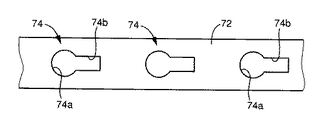
図16の固定部材72は、上記固定部材68の代わりに用いられるもので、前記ピン66に係止される爪部74は、前記係合頭部66bの径寸法より僅かに大きい円穴部74aと、その円穴部74aに連続して長手方向に設けられた前記突出部66aの径寸法より少し大きい幅寸法の長穴部74bとから成り、前記ピン66の係合頭部66bが円穴部74a内を貫通させられた後、長穴部74b側へ相対移動させられることにより、固定部材72はピン66に離脱不能に係止される。長穴部74bを、固定部材72の長手方向と直角な幅方向に形成することもできる。
【0055】
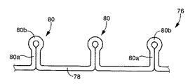
図17のバッグリテーナ76は、前記バッグリテーナ62の代わりに用いられるもので、細長い帯状の金属板を曲げ加工することにより、略一直線状に連なる本体部78、およびその本体部78から所定の間隔で突き出す複数の係止部80が形成されている。係止部80は、金属板が密着させられた幅寸法が小さい突出部80aと、金属板がループ状に回曲させられた幅寸法が大きい先端の係合頭部80bとから成り、係合頭部80bの幅寸法は回曲半径によって適宜定められる。なお、かかるバッグリテーナ76を用いる場合、前記ケース本体12およびエアバッグ14の貫通孔26,28は、上記係合頭部80bの平面視形状に対応して例えば四角形とすることが望ましい。
【0056】
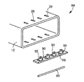
図18および図19のエアバッグケース84は請求項2に記載の発明の一実施例で、図18は組付け前の状態におけるケース本体12、1本のバッグリテーナ86、および1本の固定部材88を示す斜視図であり、図19は組付け状態における縦断面図で前記図12に対応する図である。
【0057】
バッグリテーナ86は、前記複数の貫通孔26に跨がって位置する長手形状の板状部材にて構成されているとともに、長手方向と直角な幅方向の中央部分がU字形状にせん断され且つ幅方向と平行な折曲線に沿って略直角に曲げ起こされることにより、長手方向に離間して複数の係止部90が設けられている。係止部90にはそれぞれ貫通した係止穴92が形成されており、かかるバッグリテーナ86は、プレスによるせん断、穴明け、および曲げ加工によって容易且つ安価に製造される。ケース本体12の貫通孔26およびエアバッグ14の貫通孔28は、何れも係止部90に対応して細長い溝形状を成しており、複数の係止部90がそれぞれそれ等の貫通孔28,26を共に貫通してケース本体12の外側まで突き出すとともに、そのケース本体12の外側まで突き出している係止穴92内に、丸棒状の固定部材88が長手方向の一端から順番に挿し通されることにより、バッグリテーナ86がケース本体12に離脱不能に固定されるとともにエアバッグ14の開口周縁部がケース本体12の開口周縁部に固定される。
【0058】
本実施例のエアバッグケース84においても、エアバッグ14の開口周縁部の内側にバッグリテーナ86を配設し、そのバッグリテーナ86に設けられた複数の係止部90をそれぞれ貫通孔28,26を貫通してケース本体12の外側まで突き出させ、その複数の係止部90の係止穴92内に固定部材88を挿し通せば良いため、部品点数が少なくて組付け作業を容易且つ迅速に行うことができるとともに製造コストが低減される。また、バッグリテーナ86はプレス加工によって容易且つ安価に製造できるとともに、固定部材88は単純な丸棒で複雑な加工が不要であるため、エアバッグケース84の大幅なコストダウンを図ることができる。また、固定部材88は係止穴92を挿通させられるため、係止部が門型の場合と同様に高い機械的強度が得られ、肉厚や幅寸法などの各部の寸法を小さくしたり安価な材料を採用したりすることが可能で小型且つ安価に構成できる。更に、エアバッグ14の開口周縁部はバッグリテーナ86とケース本体12との間に位置させられるため、固定部材88を配設する際にエアバッグ14と直接触れることがなく、固定部材88の組付け作業が容易である。
【0059】
なお、上記バッグリテーナ86は1つの係止部90が1枚の曲げ起こし部分によって構成されていたが、図20のバッグリテーナ94のように、2枚の曲げ起こし部分96a,96bによって1つの係止部96を構成するようにしても良い。また、丸棒状の固定部材88の代わりに角棒を用いることもできる。
【0060】
以上、本発明の幾つかの実施例を図面に基づいて詳細に説明したが、これ等はあくまでも一具体例であり、本発明は当業者の知識に基づいて種々の変更,改良を加えた態様で実施することができる。
【図面の簡単な説明】
【図1】 請求項3、4に記載の発明の一実施例であるエアバッグケースの斜視図である。
【図2】図1におけるII−II断面図である。
【図3】図1における III− III断面図である。
【図4】図1の実施例の主要な部材の組付け前の状態を示す分解図である。
【図5】図1の実施例においてバッグリテーナによりエアバッグがケース本体に組み付けられた状態の断面図である。
【図6】固定部材の別の例を示す斜視図である。
【図7】図6の(a) の固定部材を用いる場合のドアの取付部の形状を説明する斜視図である。
【図8】バッグリテーナおよびドアリテーナの別の例を説明する図である。
【図9】図8のリテーナを補強した場合の端面図である。
【図10】請求項7に記載の発明の一実施例を説明する図で、(a) は主要な部材の組付け前の状態を示す斜視図、(b) は組付け後の係止部を示す斜視図である。
【図11】図10の実施例の縦断面図である。
【図12】図11におけるエアバッグの取付部分を拡大して示す拡大断面図である。
【図13】 請求項1に記載の発明の一実施例を説明する図で、主要な部材の組付け前の状態を示す斜視図である。
【図14】図13の実施例におけるバッグリテーナの係止部を示す断面図である。
【図15】図13の実施例におけるエアバッグの取付部分を示す断面図で、図12に対応する図である。
【図16】図13の実施例に用いられる固定部材の別の例を示す図である。
【図17】図13の実施例に用いられるバッグリテーナの別の例を示す図である。
【図18】 請求項2に記載の発明の一実施例を説明する図で、主要な部材の組付け前の状態を示す斜視図である。
【図19】図18の実施例におけるエアバッグの取付部分を示す断面図で、図12に対応する図である。
【図20】図18の実施例に用いられるバッグリテーナの別の例を示す図である。
【図21】従来のエアバッグケースの一例を示す斜視図である。
【図22】図21のエアバッグケースの断面図である。
【図23】図21のエアバッグケースに用いられているリテーナの斜視図である。
【図24】従来のエアバッグケースの別の例を示す断面図である。
【符号の説明】
10,50,60,84:エアバッグケース
12:ケース本体
14:エアバッグ
16:ドア
16a:取付部
20,52,62,76,86,94:バッグリテーナ
20a,54,80,90,96:係止部
22:ドアリテーナ
22a:係止部
24,36,38,68,72,88:固定部材
26,28,30:貫通孔
42:リテーナ(バッグリテーナ,ドアリテーナ)
64:板状部材(本体部)
66:ピン(係止部)
70,74:爪部
78:本体部
92:係止穴[0001]
BACKGROUND OF THE INVENTION
The present invention relates to an improvement in an airbag case that accommodates an airbag and is disposed on an instrument panel or the like of a vehicle.
[0002]
[Prior art]
In order to protect passengers in the passenger compartment in the event of a vehicle collision, it is common practice to install an airbag on an instrument panel or the like. The airbag is generally housed in an airbag case and attached to a vehicle, and is inflated from the airbag case by generating gas from a gas generator when the vehicle collides. The
[0003]
A plurality of through holes are formed on each side of the opening peripheral portion of the
[0004]
24 is a doorless type, and can be fixed with bolts and nuts as described above. In this example, the
[0005]
[Problems to be solved by the invention]
However, there is a problem that it takes time to screw the nuts one by one into the plurality of bolts or to crimp the plurality of rivets one by one.
[0006]
The present invention has been made in the background of the above circumstances, and an object of the present invention is to make it possible to easily assemble an airbag or a door to a case body without using a nut or a rivet.
[0007]
[Means for Solving the Problems]
In order to achieve this object, the first invention is an airbag case in which an airbag is stored in the case body in a state where the opening periphery of the airbag is fixed to the opening edge of the container-like case body. Wherein (a) a plurality of through holes are provided in each of the opening peripheral edge of the case main body and the opening peripheral edge of the airbag, and (b) a position across the plurality of through holes. The case body and the airbag are disposed on the inside or outside of the peripheral edge of the opening, and are opposite to each other through the case body and the through hole of the airbag. A bag retainer integrally provided with a plurality of locking portions protruding to the side, and (c) having substantially the same length as the bag retainer and disposed on the opposite side, and the bag retainer By being locked serial engaging a plurality of engaging portions, and a fixing member for integrally fixing the rim of the opening of the case body and the air bag between its bag retainerHave and (d) The bag retainer has a main body portion having a longitudinal shape so as to be positioned across the plurality of through holes and the plurality of locking portions, and the locking portion is in the longitudinal direction of the main body portion. A projecting portion projecting from the main body portion in a direction substantially perpendicular to the projecting portion, and an engaging head projecting in a direction substantially perpendicular to the projecting direction of the projecting portion at the tip of the projecting portion, (e) The fixing member includes a plurality of claw portions that are engaged with the engaging head in the longitudinal direction, and the plurality of claw portions are engaged with the plurality of engaging heads at substantially the same timing. To be locked to the locking portion.It is characterized by that.
[0008]
2nd invention is the opening periphery of a container-shaped case main bodyPartAn airbag case in which the airbag is housed in the case body in a state where the opening edge of the airbag is fixed, and (a) the opening periphery of the case body and the opening periphery of the airbag Each is provided with a plurality of through-holes, while (b) has a longitudinal shape so as to be located across the plurality of through-holes,Inside or outside of the peripheral edge of the opening of the case body and the airbag that are overlapped with each otherAnd arranged inThe case body and airbagThrough the through holes togetherOpposite sidePlural to protrudePerson in chargeA bag retainer integrally provided with a stop, and (c) having substantially the same length as the bag retainer,Opposite sideAnd the plurality of locking portions of the bag retainerBy engaging with the bag retainer, the case body and the peripheral edge of the opening of the airbag are integrated with each other.The fixing member to be fixedHave (d) The bag retainer is configured by a longitudinal plate-like member positioned across the plurality of through-holes, and each of the plurality of locking portions has a part of the plate-like member of the plate-like member. It is bent at a substantially right angle along a bending line that is substantially perpendicular to the longitudinal direction, and a plurality of the bent portions are formed with locking holes penetrating each other, (e) The fixing member is a rod-like member, and is inserted into the locking holes of the plurality of locking portions spaced apart in the longitudinal direction of the plate-shaped member in order from one end, and the plurality of locking portions Is locked toIt is characterized by that.
[0009]
According to a third aspect of the present invention, in the state where the opening peripheral portion of the airbag is fixed inside the opening peripheral portion of the container-shaped case body, the airbag is stored in the case main body, and the airbag is stored. The door mounting portion that covers the opening of the case body is an airbag case that is fixed to the outer periphery of the opening periphery of the case body, and (a) the opening periphery of the case body, the opening periphery of the airbag And the door mounting portion are each provided with a plurality of through-holes, and (b) has an elongated shape so as to be located across the plurality of through-holes, and the airbag opening. A bag retainer integrally provided with a plurality of engaging portions disposed inside the peripheral edge and penetrating through both the airbag and the through hole of the case body and projecting to the outside of the case body; ) That A door retainer having substantially the same length dimension as that of the bug retainer and disposed on the outside of the door mounting portion, and integrally provided with a plurality of locking portions that pass through the through holes of the mounting portion; (d) The bag retainer and the door retainer have substantially the same length and are disposed between the case main body and the door mounting portion, and a plurality of latches of both the bag retainer and the door retainer. And a fixing member fixed to the case main body so as not to be detached.
[0010]
4th invention is the state which accommodated the airbag in the case main body in the state which the opening peripheral part of the airbag was being fixed inside the opening peripheral part of the container-shaped case main body, and the state which accommodated the airbag The door mounting portion that covers the opening of the case body is an airbag case that is fixed to the outer periphery of the opening periphery of the case body, and (a) the opening periphery of the case body, the opening periphery of the airbag And the door mounting portion are each provided with a plurality of through-holes, and (b) has an elongated shape so as to be located across the plurality of through-holes, and the airbag opening. A bag retainer integrally provided with a plurality of gate-shaped locking portions that are disposed on the inner side of the peripheral edge and project through the airbag and the through hole of the case body to the outside of the case body; (c) A plurality of gate-shaped locking portions that have substantially the same length as the bag retainer and are disposed outside the door mounting portion and that pass through the through-hole of the mounting portion. (C) the bag retainer and the door retainer having substantially the same length as the door retainer and disposed between the case main body and the door mounting portion, and the bag retainer and The bag retainer and the door retainer are fixed to the case main body so as not to be detached, and the bag retainer and the door retainer are fixed to the case main body.
[0011]
The fifth invention is the previousNo.In the airbag case of the invention, (a) the bag retainer has a main body portion that has a longitudinal shape so as to be positioned across the plurality of through holes, and the plurality of locking portions. The locking portion includes a protruding portion protruding from the main body portion in a direction substantially perpendicular to the longitudinal direction of the main body portion, and an engaging head protruding in a direction substantially perpendicular to the protruding direction of the protruding portion at the tip of the protruding portion. (B) The fixing member includes a plurality of claw portions that are engaged with the engaging head in the longitudinal direction, and the plurality of claw portions are provided in a plurality of engaging heads. Each of them is engaged at approximately the same timing and is locked to the locking portion.
[0012]
The sixth invention is the previousNo.In the airbag case of the invention, (a) the bag retainer is constituted by a longitudinal plate-like member positioned across the plurality of through holes, and the plurality of locking portions are respectively formed on the plates. A part of the member is bent at a substantially right angle along a fold line that is substantially perpendicular to the longitudinal direction of the plate member. (B) The fixing member is a rod-shaped member, and is inserted in order from one end into the locking holes of the plurality of locking portions provided apart from each other in the longitudinal direction of the plate-shaped member. It is made to be latched by the some latching | locking part.
[0013]
7th invention is an airbag case which accommodates the airbag in the case main body in the state by which the opening peripheral part of the airbag was being fixed inside the opening peripheral part of the container-shaped case main body, (a) A plurality of through holes are provided in each of the opening peripheral edge of the case body and the opening peripheral edge of the airbag, and (b) a long plate-like member positioned across the plurality of through holes. And a plurality of T-shaped or inverted L-shaped locking portions are provided by bending a part of the plate-like member substantially at a right angle, and inside the opening peripheral edge of the airbag. A plurality of engaging portions and a bag retainer that protrudes to the outside of the case body through the airbag and the through hole of the case body, and (c) the bag retainer Locking The T-shaped or inverted L-shaped horizontal bar portion protruding to the outside of the case main body is bent along a folding line substantially parallel to the protruding direction from the case main body, so that the case main body is detached. It is fixed to impossible.
[0014]
【The invention's effect】
1st inventionAnd the second inventionIn the case main body provided with a plurality of through-holes and on the inner or outer side of the opening peripheral edge of the airbag, a longitudinal bag retainer positioned across the plurality of through-holes is disposed, The plurality of locking portions provided on the bag retainer may be inserted into the plurality of through holes and protruded to the opposite side, and the fixing member may be locked to the plurality of locking portions. The assembly work can be easily and quickly performed with a small amount, and the manufacturing cost is reduced.That is, in the first invention,A plurality of claw portions are provided on the fixing member corresponding to the plurality of locking portions.ForIf the fixing member is assembled so that each claw part can be engaged with the locking partWell, the locking part of the second invention isIt is bent along a folding line that is substantially perpendicular to the longitudinal direction of the bag retainer and is provided with a locking hole that passes therethrough.ForA rod-shaped fixing member may be assembled so as to be inserted through the locking holes of the plurality of locking portions.
[0015]
On the other hand, in the first invention, a plurality of claw portions are provided apart from each other in the longitudinal direction of the fixing member, and the claw portions are engaged with the plurality of engaging heads at substantially the same timing, thereby fixing. Since the members are locked to the locking portions, all the claw portions are moved by moving the fixing member by the stroke required to engage one claw portion with the engaging head. Can be engaged with each engaging head almost simultaneously, and the fixing member can be assembled easily and quickly.
In the second invention, the bag retainer is constituted by a long plate-shaped member, and each of the plurality of locking portions is bent and raised along a folding line substantially perpendicular to the longitudinal direction. Therefore, when the rod-shaped fixing member is inserted in order from one end into the locking holes provided in the plurality of locking portions, the fixing member is locked to the locking portions. Therefore, although the assembly workability of the fixing member is inferior to that of the first invention, the bag retainer can be easily and inexpensively manufactured by pressing or the like, and the fixing member has a simple shape and does not require complicated processing. The cost of the air bag case can be greatly reduced. In addition, since the fixing member can be inserted through the locking hole, high mechanical strength can be obtained in the same way as when the locking portion is a gate type, and the dimensions of each part such as the wall thickness and width are reduced, and the material is inexpensive. Can be adopted, and can be configured small and inexpensively.
[0016]
A third invention relates to an airbag case of a door type, wherein a door retainer is also disposed outside the door mounting portion, and a fixing member disposed between the door mounting portion and the case main body is associated with the door retainer. Because these retainers are fixed to the case body by being locked to both the stopper and the locking portion of the bag retainer., ThatThese assembling operations can be performed easily and quickly. Further, since the fixing member and the locking portion are hidden inside the door mounting portion and the door retainer, the locking portion of the bag retainer protrudes to the outside of the door mounting portion, and the fixing member is disposed outside the mounting portion. As a result, the outer shape of the case is simpler than when the door retainer is omitted or when nuts and rivets are exposed as in the past.The
[0017]
4th invention is 3rd inventionIn one embodiment, the third invention andThe same effect can be obtainedIn addition, the locking parts provided on the bag retainer and door retainer are gate-shaped, that is, U-shaped or U-shaped, and both ends are fixed. In addition to the above, it is possible to reduce the size of each part such as the thickness and width, or to adopt an inexpensive material, so that the configuration can be made small and inexpensive.
[0018]
In the fifth invention, a plurality of claw portions are provided apart from each other in the longitudinal direction of the fixing member, and the claw portions are engaged with the plurality of engaging heads at substantially the same timing, so that the fixing member is It is configured to be locked to the locking portion. That is, by moving the fixing member by the stroke required to engage one claw portion with the engaging head, all the claw portions can be engaged with each engaging head substantially simultaneously. Therefore, the fixing member can be assembled easily and quickly.
[0019]
In the sixth aspect of the invention, the bag retainer is constituted by a long plate-like member, and each of the plurality of locking portions is bent and raised along a folding line substantially perpendicular to the longitudinal direction. Therefore, when the rod-shaped fixing member is inserted through the locking holes provided in the plurality of locking portions in order from one end, the fixing member is locked to the locking portions. Therefore, although the assembly workability of the fixing member is inferior to that of the fifth invention, the bag retainer can be easily and inexpensively manufactured by pressing or the like, and the fixing member has a simple shape and does not require complicated processing. The cost of the air bag case can be greatly reduced. In addition, since the fixing member can be inserted through the locking hole, high mechanical strength can be obtained in the same way as when the locking portion is a gate type, and the dimensions of each part such as the wall thickness and width are reduced, and the material is inexpensive. Can be adopted, and can be configured small and inexpensively.
[0020]
In the seventh invention, the bag retainer is constituted by a long plate-shaped member, and a plurality of T-shaped or inverted L-shaped locking portions are provided by bending a part of the plate-shaped member at a substantially right angle. In addition, the locking portions thereof protrude through the air bag and the through hole of the case main body to the outside of the case main body, and the T-shaped or inverted L-shaped horizontal bar portion protrudes from the case main body. The bag retainer is fixed to the case body so as not to be detached in a state in which the opening peripheral portion of the airbag is fixed between the bag retainer and the case body by being bent along a folding line substantially parallel to the direction. That is, the present invention does not require a fixing member as in the other inventions, and the bag retainer can be easily and inexpensively manufactured by pressing or the like, so that the cost of the airbag case can be greatly reduced. Further, since the locking portion is configured such that the T-shaped or inverted L-shaped horizontal bar portion is bent along a folding line substantially parallel to the protruding direction from the case body, high mechanical strength is obtained. Compared to the case of caulking as in the case of conventional riveting, the operation can be performed easily and quickly.
[0021]
DETAILED DESCRIPTION OF THE INVENTION
Here, each of the bag retainer, the fixing member, and the door retainer can be configured by a single member that can be deformed according to the shape of the opening of the case body, but the case body has a plurality of openings. In the case of forming a square shape composed of straight portions, it is desirable that the straight portions, that is, a plurality of straight members divided for each side are used. That is, when the opening of the case body has a rectangular shape such as a rectangle, a plurality of penetrating holes are provided for each side of the opening periphery of the case body, the opening periphery of the airbag, and the door mounting portion. A hole is formed, and each side is fixed using a bag retainer, a door retainer, and a fixing member. However, one side may be divided into a plurality of parts and fixed according to the present invention, respectively, and the entire circumference of the opening of the case body does not need to be fixed according to the present invention. It may simply be fixed according to the invention. In particular, it is not always necessary to fix the entire periphery of the door to the case body, and only a part such as one side may be fixed to the case body.
[0022]
1st inventionAnd the second inventionThen, as with other inventions, the peripheral edge of the opening of the airbag may be sandwiched between the case main body and the bag retainer, but the fixing member has substantially the same length as the bag retainer. The opening peripheral edge of the airbag can be sandwiched between the airbag and the fixing member. Further, the opening peripheral portion of the airbag may be overlapped with the outer periphery of the opening peripheral portion of the case main body, or the bag retainer may be provided outside the case main body and the fixing member may be provided inside. .
[0023]
4thThe fixing member in the invention may be a simple longitudinal member that can be inserted in order from one end to the other end of the plurality of locking portions as in the sixth invention, for example, but the locking portion is attached to the longitudinal main body portion. It is also possible to provide a plurality of claw portions corresponding to each of the plurality of claw portions so that the plurality of claw portions can be inserted through the locking portions, respectively. In that case, since the claw portions can be inserted through the plurality of locking portions only by moving the fixing member by a length corresponding to one locking portion, the assembling work is further facilitated.
[0024]
In the third and fourth aspects of the invention, the door retainer is also disposed outside the door mounting portion, and the fixing member disposed between the door mounting portion and the case main body is the locking portion of the door retainer and the bag retainer. The locking part of the bag retainer protrudes to the outside of the door mounting part, and a fixing member is placed outside the mounting part. In the case of the seventh invention, the door retainer can be omitted by bending the tip of the locking portion outside the mounting portion. Of course, the inventions other than the third and fourth inventions, that is, the first invention, the second invention, and the fifth to seventh inventions can be applied to an airbag case without a door. .
[0025]
In the third and fourth inventions, the locking portion of the bag retainer and the locking portion of the door retainer are engaged with a common fixing member, but the positions of these locking portions are close to each other. In the case main body, the airbag, and the door attachment portion, it is desirable that a through hole having a size that can be inserted in a state where both the locking portions are adjacent to each other is formed at the same position. Also, if the thickness of the door mounting portion is set according to the thickness of the case body and the airbag so that the height dimensions of the locking portions of both retainers engaged with the common fixing member are the same Both retainers can be used in common, and parts management and assembly work become easier.
[0026]
The bag retainer according to the fifth aspect of the present invention is constituted by, for example, a long plate-like member positioned across a plurality of through holes, and the plurality of locking portions have a part of the plate-like member at a substantially right angle. In this case, the airbag case can be manufactured easily and inexpensively by pressing or the like, and the cost of the airbag case can be reduced. The portion other than the bent and raised locking portion is the main body portion, the T-shaped or inverted L-shaped vertical bar portion corresponds to the protruding portion, and the horizontal bar portion corresponds to the engaging head. Although the direction of the folding line of the bent portion is arbitrarily determined, it is desirable that the bending direction is parallel to the longitudinal direction of the plate-like member or perpendicular to the longitudinal direction. In addition, the pin which integrally has a small-diameter cylindrical protrusion and a large-diameter cylindrical engagement head is prepared as an engaging part, and is provided on a long plate-like member or the like. The part can be configured by various means.
[0027]
Further, the claw portion of the fixing member in the fifth invention has a pair of engagement claws whose gap dimension is smaller than the width dimension of the engagement head, for example, and the engagement between the engagement claw and the engagement head. Accordingly, it is configured to be prevented from being pulled out from the locking portion. The gap between the pair of engaging claws may be smaller than the protruding portion as long as the engaging claws themselves can be elastically deformed. In this case, the engagement state with the locking portion is maintained well by the elastic force. The
[0028]
Next, embodiments of the present invention will be described in detail with reference to the drawings.
FIG.3rd invention,FIG. 2 is a cross-sectional view taken along the line II-II in FIG. 1, FIG. 3 is a cross-sectional view taken along the line III-III in FIG. 1, and FIG. It is an exploded view which shows the state before the assembly | attachment of the main members. The
[0029]
As in the case of FIGS. 22 and 24, the
[0030]
The
[0031]
The
[0032]
The through holes 26, 28, and 30 are all the same size and have a substantially square shape, and the width dimension of the locking
[0033]
The thickness of the mounting
[0034]
When assembling the
[0035]
Here, in the
[0036]
Further, since the
[0037]
Further, since the opening peripheral portion of the
[0038]
Further, since the fixing
[0039]
Further, since the
[0040]
In the above embodiment, a simple rod-like fixing
[0041]
Further, the
[0042]
The above is the claim3,Example 4 of the invention described in
[0043]
An
[0044]
The
[0045]
As is clear from FIG. 11, the
[0046]
In the
[0047]
The
[0048]
The
[0049]
The fixing
[0050]
Also in the
[0051]
In addition, since the plurality of
[0052]
10 to 12, the fixing member having substantially the same length as the
[0053]
In the above embodiment, the
[0054]
A fixing
[0055]
A
[0056]
The
[0057]
The
[0058]
Also in the
[0059]
In the
[0060]
The embodiments of the present invention have been described in detail with reference to the drawings. However, these are merely specific examples, and the present invention has various modifications and improvements based on the knowledge of those skilled in the art. Can be implemented.
[Brief description of the drawings]
FIG. 1 Claim3,4 is a perspective view of an airbag case which is an embodiment of the invention described in FIG.
FIG. 2 is a cross-sectional view taken along the line II-II in FIG.
FIG. 3 is a cross-sectional view taken along line III-III in FIG.
4 is an exploded view showing a state before the main members of the embodiment of FIG. 1 are assembled. FIG.
5 is a cross-sectional view showing a state in which the airbag is assembled to the case body by the bag retainer in the embodiment of FIG.
FIG. 6 is a perspective view showing another example of a fixing member.
7 is a perspective view for explaining the shape of a door mounting portion when the fixing member shown in FIG. 6 (a) is used. FIG.
FIG. 8 is a diagram for explaining another example of a bag retainer and a door retainer.
FIG. 9 is an end view when the retainer of FIG. 8 is reinforced.
10A and 10B are views for explaining an embodiment of the invention described in claim 7, wherein FIG. 10A is a perspective view showing a state before assembling main members, and FIG. 10B is a locking portion after assembling. FIG.
FIG. 11 is a longitudinal sectional view of the embodiment of FIG.
12 is an enlarged cross-sectional view showing an enlarged attachment portion of the airbag in FIG. 11. FIG.
FIG. 13 claims1It is a figure explaining one Example of description invention, and is a perspective view which shows the state before the assembly | attachment of main members.
14 is a cross-sectional view showing a locking portion of the bag retainer in the embodiment of FIG.
15 is a cross-sectional view showing a mounting portion of the airbag in the embodiment of FIG. 13, corresponding to FIG.
16 is a view showing another example of the fixing member used in the embodiment of FIG.
17 is a view showing another example of the bag retainer used in the embodiment of FIG.
FIG. 18 claims2It is a figure explaining one Example of description invention, and is a perspective view which shows the state before the assembly | attachment of main members.
19 is a cross-sectional view showing a mounting portion of the airbag in the embodiment of FIG. 18, corresponding to FIG.
20 is a view showing another example of the bag retainer used in the embodiment of FIG.
FIG. 21 is a perspective view showing an example of a conventional airbag case.
22 is a cross-sectional view of the airbag case of FIG. 21. FIG.
23 is a perspective view of a retainer used in the airbag case of FIG. 21. FIG.
FIG. 24 is a cross-sectional view showing another example of a conventional airbag case.
[Explanation of symbols]
10, 50, 60, 84: Airbag case
12: Case body
14: Airbag
16: Door
16a: mounting part
20, 52, 62, 76, 86, 94: Bag retainer
20a, 54, 80, 90, 96: locking part
22: Door retainer
22a: Locking part
24, 36, 38, 68, 72, 88: fixing member
26, 28, 30: through hole
42: Retainer (bag retainer, door retainer)
64: Plate member (main body)
66: Pin (locking part)
70, 74: nail part
78: Main body
92: Locking hole
Claims (7)
前記ケース本体の開口周縁部および前記エアバッグの開口周縁部にはそれぞれ複数の貫通孔が設けられている一方、
該複数の貫通孔に跨がって位置するように長手形状を成し、互いに重ね合わされた前記ケース本体および前記エアバッグの開口周縁部の内側または外側に配設されるとともに、該ケース本体およびエアバッグの貫通孔を共に貫通して反対側まで突き出す複数の係止部が一体に設けられたバッグリテーナと、
該バッグリテーナと略同じ長さ寸法を有して前記反対側に配設されるとともに、該バッグリテーナの前記複数の係止部に係止されることにより、該バッグリテーナとの間で該ケース本体およびエアバッグの開口周縁部を一体的に固定する固定部材とを有し、且つ、
前記バッグリテーナは、前記複数の貫通孔に跨がって位置するように長手形状を成す本体部と前記複数の係止部とを有するもので、該係止部は、該本体部の長手方向と略直角な方向へ該本体部から突き出す突出部と、該突出部の先端において該突出部の突き出し方向と略直角な方向へ突き出す係合頭部とを有するものである一方、
前記固定部材は、前記係合頭部と係合させられる爪部を長手方向に離間して複数備え、該複数の爪部が該複数の係合頭部にそれぞれ略同じタイミングで係合させられて前記係止部に係止されるものである
ことを特徴とするエアバッグケース。An airbag case for storing the airbag in the case body in a state where the opening edge of the airbag is fixed to the opening periphery of the container-shaped case body,
While a plurality of through holes are provided in each of the opening peripheral edge of the case body and the opening peripheral edge of the airbag,
The case main body and the case main body, which are formed in a longitudinal shape so as to be positioned across the plurality of through holes and are overlapped with each other, are disposed inside or outside the peripheral edge of the opening of the airbag, A bag retainer integrally provided with a plurality of locking portions that penetrate through the through holes of the airbag and project to the opposite side;
The case has approximately the same length as the bag retainer and is disposed on the opposite side, and is locked to the plurality of locking portions of the bag retainer so that the case is fixed to the bag retainer. A fixing member that integrally fixes the main body and the opening peripheral edge of the airbag , and
The bag retainer has a main body portion having a longitudinal shape so as to be positioned across the plurality of through holes and the plurality of locking portions, and the locking portion is a longitudinal direction of the main body portion. A projecting portion projecting from the main body portion in a direction substantially perpendicular to the projecting portion, and an engaging head projecting in a direction substantially perpendicular to the projecting direction of the projecting portion at the tip of the projecting portion,
The fixing member includes a plurality of claw portions that are engaged with the engagement head in the longitudinal direction, and the plurality of claw portions are engaged with the plurality of engagement heads at substantially the same timing. The airbag case is latched by the latching portion .
前記ケース本体の開口周縁部および前記エアバッグの開口周縁部にはそれぞれ複数の貫通孔が設けられている一方、 While a plurality of through holes are provided in each of the opening peripheral edge of the case body and the opening peripheral edge of the airbag,
該複数の貫通孔に跨がって位置するように長手形状を成し、互いに重ね合わされた前記ケース本体および前記エアバッグの開口周縁部の内側または外側に配設されるとともに、該ケース本体およびエアバッグの貫通孔を共に貫通して反対側まで突き出す複数の係止部が一体に設けられたバッグリテーナと、The case main body and the case main body, which are formed in a longitudinal shape so as to be positioned across the plurality of through holes and are overlapped with each other, are disposed inside or outside the peripheral edge of the opening of the airbag, A bag retainer integrally provided with a plurality of locking portions that penetrate through the through holes of the airbag and project to the opposite side;
該バッグリテーナと略同じ長さ寸法を有して前記反対側に配設されるとともに、該バッグリテーナの前記複数の係止部に係止されることにより、該バッグリテーナとの間で該ケース本体およびエアバッグの開口周縁部を一体的に固定する固定部材とを有し、且つ、The case has approximately the same length as the bag retainer and is disposed on the opposite side, and is locked to the plurality of locking portions of the bag retainer so that the case is fixed to the bag retainer. A fixing member that integrally fixes the main body and the opening peripheral edge of the airbag, and
前記バッグリテーナは、前記複数の貫通孔に跨がって位置するように長手形状を成す本体部と前記複数の係止部とを有するもので、該係止部は、該本体部の長手方向と略直角な方向へ該本体部から突き出す突出部と、該突出部の先端において該突出部の突き出し方向と略直角な方向へ突き出す係合頭部とを有するものである一方、The bag retainer has a main body portion having a longitudinal shape so as to be positioned across the plurality of through holes and the plurality of locking portions, and the locking portion is a longitudinal direction of the main body portion. A projecting portion projecting from the main body portion in a direction substantially perpendicular to the projecting portion, and an engaging head projecting in a direction substantially perpendicular to the projecting direction of the projecting portion at the tip of the projecting portion,
前記固定部材は、前記係合頭部と係合させられる爪部を長手方向に離間して複数備え、該複数の爪部が該複数の係合頭部にそれぞれ略同じタイミングで係合させられて前記係止部に係止されるものであるThe fixing member includes a plurality of claw portions that are engaged with the engagement head in the longitudinal direction, and the plurality of claw portions are engaged with the plurality of engagement heads at substantially the same timing. To be locked to the locking portion.
ことを特徴とするエアバッグケース。An airbag case characterized by that.
前記ケース本体の開口周縁部、前記エアバッグの開口周縁部、および前記ドアの取付部にはそれぞれ複数の貫通孔が設けられている一方、
該複数の貫通孔に跨がって位置するように長手形状を成し、前記エアバッグの開口周縁部の内側に配設されるとともに、該エアバッグおよび前記ケース本体の貫通孔を共に貫通して該ケース本体の外側まで突き出す複数の係止部が一体に設けられたバッグリテーナと、
該バッグリテーナと略同じ長さ寸法を有して前記ドアの取付部の外側に配設されるとともに、該取付部の貫通孔を貫通させられる複数の係止部が一体的に設けられたドアリテーナと、
前記バッグリテーナおよび前記ドアリテーナと略同じ長さ寸法を有して前記ケース本体と前記ドアの取付部との間に配設されるとともに、該バッグリテーナおよび該ドアリテーナの双方の複数の係止部に係止され、該バッグリテーナおよび該ドアリテーナを該ケース本体に離脱不能に固定する固定部材と
を有することを特徴とするエアバッグケース。In the state where the opening periphery of the airbag is fixed inside the opening periphery of the container-shaped case body, the airbag is stored in the case body, and the opening of the case body is stored in the state where the airbag is stored. An airbag case in which a door mounting portion covering the portion is fixed to the outer periphery of the opening periphery of the case body,
While the opening peripheral portion of the case body, the opening peripheral portion of the airbag, and the attachment portion of the door are each provided with a plurality of through holes,
A longitudinal shape is formed so as to straddle the plurality of through-holes, and is disposed inside the opening peripheral edge of the airbag, and penetrates both the airbag and the case body through-holes. A bag retainer integrally provided with a plurality of locking portions protruding to the outside of the case body,
A door retainer having substantially the same length as the bag retainer and disposed outside the door mounting portion, and integrally provided with a plurality of locking portions that pass through the through holes of the mounting portion. When,
The bag retainer and the door retainer have substantially the same length and are disposed between the case body and the door mounting portion, and a plurality of locking portions of both the bag retainer and the door retainer. An airbag case having a bag retainer and a fixing member that detachably fixes the door retainer to the case body.
前記ケース本体の開口周縁部、前記エアバッグの開口周縁部、および前記ドアの取付部にはそれぞれ複数の貫通孔が設けられている一方、
該複数の貫通孔に跨がって位置するように長手形状を成し、前記エアバッグの開口周縁部の内側に配設されるとともに、該エアバッグおよび前記ケース本体の貫通孔を共に貫通して該ケース本体の外側まで突き出す複数の門型の係止部が一体に設けられたバッグリテーナと、
該バッグリテーナと略同じ長さ寸法を有して前記ドアの取付部の外側に配設されるとともに、該取付部の貫通孔を貫通させられる複数の門型の係止部が一体的に設けられたドアリテーナと、
前記バッグリテーナおよび前記ドアリテーナと略同じ長さ寸法を有して前記ケース本体と前記ドアの取付部との間に配設されるとともに、該バッグリテーナおよび該ドアリテーナの双方の複数の係止部の内側を挿通させられ、該バッグリテーナおよび該ドアリテーナを該ケース本体に離脱不能に固定する固定部材と
を有することを特徴とするエアバッグケース。In the state where the opening periphery of the airbag is fixed inside the opening periphery of the container-shaped case body, the airbag is stored in the case body, and the opening of the case body is stored in the state where the airbag is stored. An airbag case in which a door mounting portion that covers the portion is fixed to the outer periphery of the opening periphery of the case body,
While the opening peripheral portion of the case body, the opening peripheral portion of the airbag, and the attachment portion of the door are each provided with a plurality of through holes,
A longitudinal shape is formed so as to straddle the plurality of through-holes, and is disposed inside the opening peripheral edge of the airbag, and penetrates both the airbag and the case body through-holes. A bag retainer integrally provided with a plurality of gate-shaped locking portions protruding to the outside of the case body;
A plurality of gate-shaped locking portions that have substantially the same length as the bag retainer and are disposed on the outside of the door mounting portion and that pass through the through hole of the mounting portion are integrally provided. Door retainer,
The bag retainer and the door retainer have substantially the same length and are disposed between the case body and the door mounting portion, and a plurality of locking portions of both the bag retainer and the door retainer. An airbag case having an inner side inserted therein and a fixing member that detachably fixes the bag retainer and the door retainer to the case main body.
前記バッグリテーナは、前記複数の貫通孔に跨がって位置するように長手形状を成す本体部と前記複数の係止部とを有するもので、該係止部は、該本体部の長手方向と略直角な方向へ該本体部から突き出す突出部と、該突出部の先端において該突出部の突き出し方向と略直角な方向へ突き出す係合頭部とを有するものである一方、
前記固定部材は、前記係合頭部と係合させられる爪部を長手方向に離間して複数備え、該複数の爪部が該複数の係合頭部にそれぞれ略同じタイミングで係合させられて前記係止部に係止されるものである
ことを特徴とするエアバッグケース。In the airbag case according to claim 3 ,
The bag retainer has a main body portion having a longitudinal shape so as to be positioned across the plurality of through holes and the plurality of locking portions, and the locking portion is a longitudinal direction of the main body portion. A projecting portion projecting from the main body portion in a direction substantially perpendicular to the projecting portion, and an engaging head projecting in a direction substantially perpendicular to the projecting direction of the projecting portion at the tip of the projecting portion,
The fixing member includes a plurality of claw portions that are engaged with the engaging head in the longitudinal direction, and the plurality of claw portions are engaged with the plurality of engaging heads at substantially the same timing. The airbag case is locked to the locking portion.
前記バッグリテーナは、前記複数の貫通孔に跨がって位置する長手形状の板状部材にて構成され、前記複数の係止部は、それぞれ該板状部材の一部が該板状部材の長手方向と略直角な折曲線に沿って略直角に曲げ起こされたもので、該曲げ起こされた複数の係止部にはそれぞれ貫通した係止穴が形成されている一方、
前記固定部材は棒状の部材で、前記板状部材の長手方向に離間して設けられた前記複数の係止部の前記係止穴内に一端から順番に挿通させられて、該複数の係止部に係止されるものである
ことを特徴とするエアバッグケース。In the airbag case according to claim 3 ,
The bag retainer is configured by a longitudinal plate-like member positioned across the plurality of through-holes, and each of the plurality of locking portions includes a part of the plate-like member. While bent at a substantially right angle along a bending line that is substantially perpendicular to the longitudinal direction, a plurality of locking portions that are bent and raised have through holes formed therein,
The fixing member is a rod-shaped member, and is inserted through the locking holes of the plurality of locking portions spaced apart in the longitudinal direction of the plate-shaped member in order from one end, and the plurality of locking portions An air bag case that is locked to the air bag.
前記ケース本体の開口周縁部および前記エアバッグの開口周縁部にはそれぞれ複数の貫通孔が設けられている一方、
該複数の貫通孔に跨がって位置する長手形状の板状部材にて構成されているとともに、該板状部材の一部が略直角に曲げ起こされることによりT字形または逆L字形の複数の係止部が設けられ、前記エアバッグの開口周縁部の内側に配設されるとともに該複数の係止部がそれぞれ該エアバッグおよび前記ケース本体の貫通孔を共に貫通して該ケース本体の外側まで突き出すバッグリテーナを有し、
該バッグリテーナは、前記係止部のうち前記ケース本体の外側まで突き出している前記T字形または逆L字形の横棒部分が、該ケース本体からの突き出し方向と略平行な折曲線に沿って折り曲げられることにより、該ケース本体に離脱不能に固定されている
ことを特徴とするエアバッグケース。An airbag case for storing the airbag in the case body in a state where the opening edge of the airbag is fixed inside the opening periphery of the container-shaped case body,
While a plurality of through holes are provided in each of the opening peripheral edge of the case body and the opening peripheral edge of the airbag,
A plurality of T-shaped or inverted L-shaped members are formed by a plate-shaped member having a long shape positioned across the plurality of through-holes, and a part of the plate-shaped member is bent at a substantially right angle. And the plurality of locking portions respectively penetrate through the through holes of the airbag and the case main body, and are disposed inside the peripheral edge of the opening of the airbag. A bag retainer that protrudes to the outside,
In the bag retainer, the T-shaped or inverted L-shaped horizontal bar portion of the locking portion protruding to the outside of the case body is bent along a folding line substantially parallel to the protruding direction from the case body. The airbag case is fixed to the case body so as not to be detached.
Priority Applications (1)
| Application Number | Priority Date | Filing Date | Title |
|---|---|---|---|
| JP00662896A JP3761237B2 (en) | 1995-09-29 | 1996-01-18 | Air bag case |
Applications Claiming Priority (3)
| Application Number | Priority Date | Filing Date | Title |
|---|---|---|---|
| JP25211895 | 1995-09-29 | ||
| JP7-252118 | 1995-09-29 | ||
| JP00662896A JP3761237B2 (en) | 1995-09-29 | 1996-01-18 | Air bag case |
Publications (2)
| Publication Number | Publication Date |
|---|---|
| JPH09150701A JPH09150701A (en) | 1997-06-10 |
| JP3761237B2 true JP3761237B2 (en) | 2006-03-29 |
Family
ID=26340817
Family Applications (1)
| Application Number | Title | Priority Date | Filing Date |
|---|---|---|---|
| JP00662896A Expired - Fee Related JP3761237B2 (en) | 1995-09-29 | 1996-01-18 | Air bag case |
Country Status (1)
| Country | Link |
|---|---|
| JP (1) | JP3761237B2 (en) |
Families Citing this family (1)
| Publication number | Priority date | Publication date | Assignee | Title |
|---|---|---|---|---|
| JP2007245876A (en) | 2006-03-15 | 2007-09-27 | Takata Corp | Air bag device |
-
1996
- 1996-01-18 JP JP00662896A patent/JP3761237B2/en not_active Expired - Fee Related
Also Published As
| Publication number | Publication date |
|---|---|
| JPH09150701A (en) | 1997-06-10 |
Similar Documents
| Publication | Publication Date | Title |
|---|---|---|
| US5303951A (en) | Air bag assembly with housing and fastenerless deployment door | |
| EP1331141B1 (en) | Fixing method and structure of inflator, and airbag apparatus | |
| US5354093A (en) | Air bag module having integral cover attachment | |
| JP2008020006A (en) | High fixing strength fixture | |
| US20070063490A1 (en) | Mounting structure for curtain airbag | |
| EP0739788A1 (en) | Cover attachment for an air bag module | |
| JPH09216545A (en) | Air bag device and manufacture thereof | |
| US5794967A (en) | Passenger air bag module with means for retaining an air bag deployment door to a housing | |
| WO2003031230A2 (en) | Airbag module z-height control tab | |
| CN117601795A (en) | Improved fastening clamp | |
| JP3761237B2 (en) | Air bag case | |
| JP3505885B2 (en) | Airbag device | |
| DE102011000051A1 (en) | airbag module | |
| JPH11268602A (en) | Air bag device | |
| JP5251262B2 (en) | Vehicle hood structure | |
| JP5067262B2 (en) | Vehicle hood structure | |
| US20040036268A1 (en) | Energy absorbing turning loop cover | |
| JP3666996B2 (en) | Air bag case | |
| JPH09240408A (en) | Air bag device | |
| JP3375219B2 (en) | Airbag device | |
| JP4244132B2 (en) | clip | |
| JP2010058607A (en) | Airbag device | |
| KR0138715Y1 (en) | Mounting Structure of Car Carpet | |
| JP4488632B2 (en) | Reinforcement for vehicle instrument panel | |
| JPH08310326A (en) | Air bag device for front passenger seat |
Legal Events
| Date | Code | Title | Description |
|---|---|---|---|
| A977 | Report on retrieval |
Free format text: JAPANESE INTERMEDIATE CODE: A971007 Effective date: 20050224 |
|
| A131 | Notification of reasons for refusal |
Free format text: JAPANESE INTERMEDIATE CODE: A131 Effective date: 20050301 |
|
| A521 | Written amendment |
Free format text: JAPANESE INTERMEDIATE CODE: A523 Effective date: 20050331 |
|
| TRDD | Decision of grant or rejection written | ||
| A01 | Written decision to grant a patent or to grant a registration (utility model) |
Free format text: JAPANESE INTERMEDIATE CODE: A01 Effective date: 20051220 |
|
| A61 | First payment of annual fees (during grant procedure) |
Free format text: JAPANESE INTERMEDIATE CODE: A61 Effective date: 20060110 |
|
| R150 | Certificate of patent or registration of utility model |
Free format text: JAPANESE INTERMEDIATE CODE: R150 |
|
| FPAY | Renewal fee payment (event date is renewal date of database) |
Free format text: PAYMENT UNTIL: 20090120 Year of fee payment: 3 |
|
| FPAY | Renewal fee payment (event date is renewal date of database) |
Free format text: PAYMENT UNTIL: 20100120 Year of fee payment: 4 |
|
| FPAY | Renewal fee payment (event date is renewal date of database) |
Free format text: PAYMENT UNTIL: 20100120 Year of fee payment: 4 |
|
| FPAY | Renewal fee payment (event date is renewal date of database) |
Free format text: PAYMENT UNTIL: 20110120 Year of fee payment: 5 |
|
| LAPS | Cancellation because of no payment of annual fees |