JP3760249B2 - Disaster safety device - Google Patents
Disaster safety device Download PDFInfo
- Publication number
- JP3760249B2 JP3760249B2 JP20986295A JP20986295A JP3760249B2 JP 3760249 B2 JP3760249 B2 JP 3760249B2 JP 20986295 A JP20986295 A JP 20986295A JP 20986295 A JP20986295 A JP 20986295A JP 3760249 B2 JP3760249 B2 JP 3760249B2
- Authority
- JP
- Japan
- Prior art keywords
- frame
- safety device
- reinforcing
- view
- bed
- Prior art date
- Legal status (The legal status is an assumption and is not a legal conclusion. Google has not performed a legal analysis and makes no representation as to the accuracy of the status listed.)
- Expired - Lifetime
Links
Images


Description
【0001】
【産業上の利用分野】
この発明は、地震(津波を含む)、土砂崩れ、台風、洪水等の種々の災害に有効に機能するようにした災害安全装置に関する。
【0002】
【従来の技術】
例えば、近年では地震や津波あるいは土砂崩れ等が激烈なものになっているのが現状である。
【0003】
【発明が解決しようとする課題】
そのための対策として、本出願人は先にカプセル体に関する提案をしたのであるが、コスト的な問題もここに考慮しつつより安全性の高い災害対策を採る必要があることを痛感した。
【0004】
この発明は前記課題を解決するためになされたもので、その目的とするところは、コスト的にも安価につき、しかも、安全性の高い災害安全装置を提供することにある。
【0005】
【課題を解決するための手段】
前記課題を解決するため、請求項1記載の発明は、複数本の支柱とこれらを互いに連結する連結部材とにより枠状とされ内部にベッド本体が装備されるようになっている耐震構造体を備えた災害安全装置であって、前記耐震構造体は、床面で支承される以外に床下補強支柱を介して建造物の床下基盤側に対しても支承されていることを特徴とする。
【0006】
請求項2記載の発明は、請求項1記載の発明において、床下補強支柱は、その下端が床下基盤にアンカーで固定されている一方上端は耐震構造体の底部に連結固定されている。
【0007】
請求項3記載の発明は、複数本の垂直なコーナー支柱とこれらを互いに上端および下端において連結する連結部材とにより枠状とされ内部にベッド本体が装備されるようになっている耐震構造体でなる災害安全装置であって、前記耐震構造体の上側および底側の双方には緩衝部材が設けられていることを特徴とする。
請求項4記載の発明は、上方に凸状をなす左右一対のアームとこれら相互間を上部に位置する中央部および下端において連結する部材とによりアーチ状とされた安全枠体の内部に寝具を備えた災害安全装置であって、前記安全枠体の上側および底側の双方には緩衝部材が設けられていることを特徴とする。
【0008】
【実施例】
以下、図示実施例を参照してこの発明を詳細に説明する。
【0009】
図1は、耐震構造体として形成したものである。
【0010】
実施例では1段であるが仮想線のように2段でもよい。同耐震構造体は、木製ではなく、強度の充分な金属が使用されている。
【0011】
すなわち、57は枠状の耐震構造体で、縦4本の支柱とこれらの底部間および上部間をつなぐ連結部材とでなり、ブレース58…でさらなる強度アップが図られている。
【0012】
その中段やや下方には、床板59が複数に分割して剥ぎ取り自在に配され、60はそのための把手になる穴である。
【0013】
そして、床板59の下方の空間には、開閉扉61で出し入れ自在な非常収納ボックス62…が設けられている。
【0014】
同耐震構造体57には入口扉63が設けられて通常出入り可能であり、その内部には、生活必要手段を入れるボックス64が常時備え付けられている。そして、就寝中に地震等が発生した場合、耐震構造体57そのもので安全が確保されるとともに、その後も、ボックス62,64で非常時に必要な生活が可能である。
【0015】
勿論、トイレや水、空気等も全てボックス62,64から供給可能である。尚、この耐震構造体57は、突っ張り65や床下補強支柱66などにより更に補強され得る。同耐震構造体57は、屋外に設置可能でもある。耐震構造体57外部に全体的に張り付けられる防護板56は、耐火物で強度のある部材を用いる。ボックス62,65には、靴を入れておいたり、電気コンセントや非常時にそれを利用可能な機器、クーラーなどを組み込んでおくこともできる。
【0016】
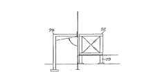
図2は、建造物内の机72を耐久構造体とした例を示す。この机72は、床を通じて補強柱73で更に強度アップを図るようにしてもよく、また、この机72内の空間が避難空間になることから、同空間を通じて外部に脱出可能にも構成する。この場合、補助通路のため、ガード74を付する。
【0017】
図3は、机93を一体成形により耐久構造体とし、更に内部埋め込み式に金属板からなる骨組み94を組み込んだものである。支柱95で更に強化を図ってもよい。ボックス96も適宜に配す。また仮想線のように、構造体97の一部で机93を構成してもよい。
【0018】
図4は、建造物内でのタンス99等の家具が倒れて互いにハの字に構成されるようにしたものである。タンス99の上端角部には当たり100が取り付けられているとともに、バネ101でタンス99が一定以上は倒れないように工夫されている。尚、リンク102で角度規制してもよい。
【0019】
図5に示す実施例は、耐震構造体130の本体をアングル(金属)材などにより耐震構造としてその内部に非常用具ボックス131を備え付けたものにおいて、同耐震構造体130の上面に更に強度上板132を載せ付けるとともに、本体の底部にも強度下板133をブラケット134にて結合して強度アップを図ったものである。強度上板132および強度下板133は、木質あるいは金属質更にプラスチックなど材料は自由に選択する。尚、底部には可動用のローラー135が取り付けられている。
【0020】
図6に示す実施例は、図5のような耐震構造体130を床盤137にアンカー固定された4本の床下補強支柱138にも結合して更に耐震構造としたものである。139は床板で、耐震構造体130はこの床板139上に支承される以外に床下補強支柱注138を介して床盤137上にも支承されている。補強支柱138の上端は耐震構造体130側に連結固定されている。
【0021】
図7に示す実施例は、耐震型食卓机141や事務机などの脚部142回りに回転操作可能なように椅子143を配したもので、この平面図は、図10にも示されているように、4点(あるいはその他の数点)配置になっている。椅子143は、ステー144を介して食卓机141に連結されているので、それが机の下方あるいは外部のいずれにあっても地震発生時に耐震構造の一部として有効に機能する。145はストッパである。
【0022】
図8に示す実施例は、飾り棚147全体をゴム等の緩衝体148で耐震支持させるとともに、同棚147自体を支持棒149回りに緩衝筒150を介装して耐震構造にしたものである。
【0023】
図9に示す実施例は、勉強等の耐震構造の机152を緩衝体153で下支持し、それに椅子154を対応させたものにおいて、机152を耐震枠155で大きく覆い、さらに椅子154の背柱156を枠155の上部と結合して耐震構造としたものである。尚、仮想線で示すように机152は耐震枠153と一体化してもよい。
【0024】
図11に示す実施例は、カバー326付きの枕本体327を例えば、クッション材とし、その一部を切開溝328として形成して、地震などの非常時には同溝328を仮想線のように大きく開いて頭に被ることにより家屋等からの落下に備えるようにしたものである。
【0025】
図12に示す実施例は、枕本体329を左右2つの部分から構成してクイックファスナで相互に着脱自在に連設するとともに、破線のように脚入れ孔330をそれぞれに形成したもので、非常時には、左右を分けて孔330に脚を挿入することでガラスなどで怪我をせずに避難等ができるようにしたものである。
【0026】
図13および図14に示す実施例は、就寝中等に使用される枕340がそのまま地震発生後に避難用具として使えるようにしたものである。この枕340は、図13に示すように、内部に避難用具が収納されていて、ファスナー341を開けば簡単に取り出せるようにされているとともに、その外層部は通常の枕として使えるように柔軟になっている。そして、外袋342で包まれている。枕340は2つ折り型とされて、面ファスナー343でその状態を保持できるようになっている。面ファスナー343を外せば、矢印のように展開でき、紐344が同時に出るので、図14に示すように背負って避難することができるのである。そして展開した状態では、ファスナー341を開ければ内部から避難用具を取り出せるのである。
【0027】
図15に示す実施例は、同じく枕346についての案で、同枕346は、横に少し長目に作られ、その一側が枕部347とされる一方、他側がファスナー348の開閉で避難用具を取り出せるものになっている。同他側も少し柔軟な外層になっている。そして、避難用紐349は、金具350に直接取り付けておいてもよいが、枕部347の一側のファスナー348を開けることで取り出せ、通常はここに仕舞っておくことができる。
【0028】
図16に示す実施例は、市販で一般家庭等で既に使用されている洋風ベッド(本体)381を地震対策のために包囲して防護した例である。同ベッド381を防護する耐震構造体は、4本の補強用のコーナー支柱382…と、これらの支柱382…を下端において連結する底枠部材(連結部材)383…と、支柱382…を上端において連結する天枠部材(連結部材)384…とで耐震構造体を構成する。これらは金属製でジョイント385…で相互に強固に連結されるとともに、ブレース386…で更なる補強がなされる。底部には、緩衝部材387が敷設されるとともに、天枠部材384…には、受板388…を介して肉厚の大きな緩衝部材389が効果的な緩衝をするように備え付けられている。尚、支柱382とベッド381とは連結片390で連結され、底枠部材383…も耐震構造体381の底と連結するようにしてもよい。尚、仮想線で示すように、補強体の天底面には、緩衝内張材391を装備しておけば、より安全である。この内張材391に代えてあるいは同内張材391とともにエアーバッグを装備してもよい。このことは、図27から図35でも可能である。
【0029】
図17および図18は、一般家庭で既に使用されている2段ベッドあるいはこれから販売される2段ベッドを対象にしてそれに補強を追加補充し、地震時に有効に機能するようにした実施例を示している。同ベッドは、1段あるいは3段以上であってもよい。既存のベッドは、木質で四角な断面の支柱392…を四隅に配し、これらの支柱392…間を底枠材393…と中段枠材394…で連結するとともに各枠材393…、394…内に底敷材395を配して構成されている。尚、上段連結材396も渡してある。このベッドは、ベッド幅方向に直交する方向が長手方向とされた矩形状でその四辺に枠材を備えたベッド枠体上にベッド本体を設置するようにしたものである。
【0030】
ベッド補強構造体はこの既存のベッドのまわりを取り囲むようにして設置されている。すなわち、同構造体は、基本的に金属質で製作され、アングル型をして前記支柱392の二面に添うようにして前記ベッド枠体の四隅に対応して立ち上がる4本の支柱398…と、これらの支柱398…の下端を連結する一対の第1底枠材399…と、同じく支柱398…の下端を連結する一対の第2底枠材400…とを備えるとともに、支柱398…の中段間を連結する中段枠材401…と、上段連結材402…とを備える。これらは、予め組み立てられるのでなく現場でジョイント板403…と装飾ボルト404…を使って連結される。現場組立のため、支柱398…は、図18に仮想線で示すように連結ボルト・ナット405…で既存ベッド側に止め付けられ、これが既存ベッドと補強構造体との一体化を可能にする。
【0031】
支柱398…の各下端には、図18に示すように、支柱398の一側面とそれに隣合う他側面とに合致する略L字形をした座板406…が溶接等により固着されており、同座板406…の底側には、緩衝部材407…が介装されるとともに、座板406…同士は前記第2底枠材400…でボルト連結されている。また、各支柱389…の上端には上座板408…が取り付けられ、それに緩衝部材407…を介してその上に天枠409の取付板410…が乗りかかってボルト止めされている。天枠409は、前記支柱389…のうち前記長手方向に対応するものの上端間を結ぶとともに左右一対からなる耐力のあるアーチ形にしており、そのアーチは上方に凸状をなしている。複数本のアーチ間連結材412…を含む天枠409,409上には、安全のための覆いである厚みのある主緩衝部材411が載せられて適宜装着される。尚、アーチ間連結材412…は、天枠409,409の左右(ベッド幅方向)間を結合するもので、ベッド長手方向に複数本間隔を置いて配列されている。また、補強体の天底面には、緩衝内張材381(図16参照)を装着しておけば、より安全である。この内張材391に代えてあるいは同内張材391とともにエアーバッグを装備してもよい。
【0032】
図19は、支柱392にアングル型の補強用支柱413を当て付けるようにして補足する場合の他の例を示している。支柱413には、二辺に孔414…が開けられており、この孔414…を通じてボルト415…が挿通されている。このボルト415…の先端には、支柱392の内側に当て付けられる保持片416にねじ込まれ、このねじ込みにより支柱392の回りに支柱413と保持片416が締め付け固定される。尚この構造は、支柱392の上下に複数段構成されている。この構造にすることにより、支柱392の断面寸法が大小様々であっても対応できる。そのため、前記孔414は長孔(あるいはばか孔)になっている。
【0033】
図20も支柱392にアングル型の補強用支柱418を締着する例を示している。419は長孔形(あるいはばか孔形)をした支柱418の孔、420はボルト、421は支柱392に沿って上下方向に配されるL形のアングル、422はこのアングル421の上下方向に沿って溶接されて上下の組で支柱392の角を捉えるように配したナットである。
この構造によっても支柱392の寸法が異なっても共通のもので対応することができる。
【0034】
図21および図22は、ベッドの側面に付加される側枠についての変形例を示している。図21の側枠は、上・下部材424,425と、これらの間を斜めに継ぐ斜材426と、連結板427と、リブ428とでなる。上・下部材424,425と斜材426とはボルト429で現場組立可能に連結するようにしてもよい。430は緩衝部材である。尚、仮想線のように、X形にする斜材426を追加してもよい。
【0035】
図22は、上・下部材431,432と、その間を垂直に継ぐ縦部材433と、連結板434とでH形に形成された側枠を示している。連結板434にはボルトを備えてもよい。尚、図21および図22の側枠は、1つのベッドに対して図示したもの1つあるいは一対配してもよい。一対の場合は相互間を天間等で連結するようにしてもよい。該天間等の連結部材は、1本あるいは2本など自由である一方、上からみてZ形やX形、H形になるように配してもよい。
【0036】
図23は、内部に備えた和風寝具436により就寝する場合の安全枠体についての実施例を示す。同枠体は、左右一対の上方に凸状をなすアーチ437…と、これらの上部に位置する中央部および下端間を継ぐ横架材(連結部材)438とを備える。これらは現場組立可能にボルトで着脱自在にしてもよい。尚、枠体の上端と下端には緩衝部材439を設けてあるが、更に、アーチ437の外周に沿って緩衝部材を付してもよい。また、緩衝部材439は枠体の上面全体を覆うものとしてもよい。さらに、アーチ437は、側方からみて山形にしてもよい。尚、補強体の天底面には、緩衝内張材390を装備しておけば、より安全である。この内張材390に代えてあるいは同内張材390とともにエアーパッグを装備してもよい。
【0037】
図24は、同じく和風寝具で就寝する場合の安全枠体の他の例を示す。すなわち、正面からみて山形になるように左右一対のアーチ440を斜め配置して底板441で支持し、底部および上端に緩衝部材442を配したものである。より強く抵抗する。
【0038】
尚、アーチは上からみて敷き布団を斜めに横断する1本のものであってもよく、また、上からみてX字に配してもよい。
【0039】
図25は、寝たきりの人や入院中の人を護るために考えらえれた実施例である。簡易ベッドは、手すりパイプ444を備え、これに対し、ガード445は、パイプ444に締着される前後1対の曲げパイプ445と、2分割型の取付筒446…と、曲げパイプ445間を連結する連結パイプ447と、斜材448とでなる。天部には緩衝部材を覆ってもよい。尚、この場合も、図23あるいは図24で示すアーチ型の補強枠を使用できる。尚、補強体の天底面には、緩衝内張材390を装備しておけば、より安全である。この内張材390に代えてあるいは同内張材390とともにエアーバッグを装備してもよい。
【0040】
図26も簡易ベッドの補強構造を示す。同構造は、手すりパイプ450の中間にあるように垂直に配された補強ステー451と、手すりパイプ450の上側に配置された補助パイプ452とを備え、ステー451、手すりパイプ450および補助パイプ452の三者、並びに手すりパイプ450と補助パイプ452相互が合わせ型の連結パイプ453…で締め付けられているとともに、手すりパイプ450と補助パイプ452とは側部においても連結ロッド454で結合されている。尚455は天枠である。
【0041】
図27、図28および図29は、食卓などの既存あるいはこれから販売される4本脚タイプのテーブル457を補強の対象にした実施例を示している。これらの図において、中心線を境に左側は、天板458に垂直に脚459が取り付けられたタイプを示し、右側は、脚459がやや斜めに取り付けられたものを示している。
【0042】
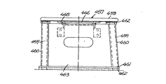
460は補強脚で、円筒の金属パイプでなり、脚459の外周に嵌め合わされている。前後の補強脚460の下端間は、底座461で連結され、その底側には緩衝部材462が設けられている。また、前後の補強脚460間は、他の縦板463で連結一体化されている。尚、脚459が垂直な場合は、縦板463付の補強脚460を脚459に一体のまま挿通できるが、脚459が斜めの場合には、補強脚460を2分割式で合わせ型とするか、あるいは縦板463をボルト等で現場で補強脚460に合体させるものとする。
【0043】
補強脚460の上端には天座464が取り付けられ、同天座464と天板458間には、緩衝部材462が介装されている。尚、補強脚460は、各種径サイズのものがあることから、充分大きな内径をもつもので共通に対応できるようにすることもある。同補強脚460は角筒でもよい。縦板463の内側にはブラケット465を介して偏平筒状の受板466が天板458の底面に添うように取り付けられている。尚、天板458と受板466との間にも緩衝部材を入れて緩衝機能の他、寸法調整用のスペーサとしても機能するようにできる。前記補強脚460は、L型アングルあるいは溝型チャンネル材を使用できる。テーブル内には非常避難用具のボックスを設置できる。この場合、縦板463を背板として利用できる。
【0044】
図30および図31は、テーブル468内の空間に少し小さ目の補強体469を設置して補強機能を発揮するようにした実施例を示す。同補強体469は、偏平な四角筒状の補強脚470の1対と、各脚470の下端に固着した座471と、その底の緩衝部材472と、補強脚470間に渡された受板473とを備え、緩衝部材474と補助緩衝部材475を介して天板476に当たっている。下側の緩衝部材472および上側の緩衝部材474あるいは補助緩衝部材475はテーブル468と補強体469との寸法差を吸収する。尚、477は避難用具ボックスである。
【0045】
図32は、脚479に離れて補強脚480を配したもので、その下端をアジャスタ481で昇降調節可能にしたものである。
【0046】
図33は、テーブル483の内空間に四角ブロック状の緩衝部材484を入れ込み、上側の薄い補助緩衝部材485で寸法吸収可能にするとともに、同緩衝部材484内を長円形などに抉って避難空間たる補強体486を挿入したものである。487は避難用具ボックスである。
【0047】
尚、仮想線で示すように補強体をテーブル483よりはみ出すようにしてもよい。この部分は、避難用具入れとしたり、通常生活用の用具入れなどとして利用できる他、災害防護機能が大きくなる。
【0048】
図34は、天板488の脚489を補強脚490と連結板491でつないだものにおいて、同連結板491を分割して寸法調整自在にボルト止めしたものである。
【0049】
図35は、脚493が中央に1枚設けられたテーブルを対象にして、同脚493の前後にあるように補強脚494とこれを継ぐ連結部材495を設けたもので、補強脚494の下端の座496は緩衝部材497で受られる一方、上端にはアングル等の長い受部材498が設けられ、この受部材498は、テーブルの長さ方向に延びて向こう側の補強脚494に連結されている。
【0050】
図36は、タンスなどの家具500の転倒防止装置を示している。畳501を利用して同畳501の家具500の後方隅にあるようにL形ブラケット502を装着して家具500の重さでブラケット502が効果的に固定されるようにしてある。尚、同ブラケット502は床板に釘止めやねじ止めしてもよい。一方、家具500の前コーナーには止め金具503をセットし、同金具503とブラケット502間にターンバックル504を備えて長さ調節可能な引きロッド505を通してある。只、ロッド505の上端には、バネ506が設けられているが、ナットで固定化してもよい。
【0051】
図37および図38に示す実施例は、椅子507に座って事務机や勉強机等の机508で事務処理等をする者を地震から護るための防護装置509についてのものである。同防護装置509は、相対向して座る人を防護するように構成され、その他の防護の態様については後述する。
【0052】
防護装置509は、略半円形に曲げられた金属パイプ製のメインフレーム510を共通部材として4本備え、同フレーム510は、側方からみてX字形に反り返るように配されるとともに、その間が連結部材511で継がれ、また、座る人の上方を通るように横架部材512で継がれている。尚、仮想線のように、前後のメインフレーム510間を上部連結部材513で継いでもよい。尚、連結部材511は、回転自在なヒンジ結合にしてもよい。
【0053】
メインフレーム510の各下端には補強部材515を介してL字あるいはコの字形のブラケット516が取り付けられ、同ブラケット516は、緩衝材517を介してアンカー518により床519に固定されている。左右に対向する連結部材511間には、棚520が形成される一方、メインフレーム510の各上端には、分割線521により着脱自在とされた緩衝材522とキャップ523が装着されている。
【0054】
尚、事務机は一般に左右方向に複数個配列されるので、図37、図38のように各個ずつに防護装置509を構成せず、複数個ある机の左右両側端にのみメインフレーム510を構成してそれらの間を横架部材512で継ぐように構成してもよく、例えば、4個ある机のうち2個ずつに対して図37、図38の防護装置を構成してもよい。さらに、連結部材511、上部連結部材513、横架部材512等はそのうち1つ以上を選択的に着脱自在な連結にしてもよい。横架部材512にも緩衝材を付してもよい。また、図38に仮想線で示すように、机508や床519あるいは椅子507から上方に延びるフレーム受524を設けてもよい。さらに、メインフレームは、側面形状がV形になるように形成してもよい。
【0055】
また、図39に示す実施例のように、単一本のメインフレーム510で防護装置を構成してもよい。この場合、下部を仮想線のようにL字形に曲げてもよく、また、連結部材526を備えて対向する側に着脱自在にしてもよい。さらに、仮想線のように、椅子507の側方を立ち上がるようなメインフレーム527にしてもよい。また、フレーム510は、円形に曲げて後方の者をも防護するように構成することもできる。
【0056】
図40および図41は、喫茶店内のテーブル530に付属の椅子531に座る者の防護装置532についての実施例を示す。同装置532は、メインフレーム533、連結部材534,534、上部連結部材535、横架部材536、ブラケット537、緩衝材538を備え、アンカー539で固定された一体型のものである。横架部材536にも緩衝材540が取り付けられ、左右のフレーム533間には、横連結板541が設けられてその上にテーブル530が設置されている。横連結板541は無しにしてテーブル530をフレーム533に連結してもよい。尚、連結部材534は筐体になっていてその中にプランター542をセットして花を鑑賞できるようにしてある。テーブルは会議用の机や食堂机等でもよい。フレーム533相互は、左右に対してあるいは前後に対して着脱自在にしてもよい。テーブル530は、既存の脚付きのものとし、それを囲むような防護装置を構成してもよい。前記防護装置も複数個のテーブルに対してその全体あるいは複数一部個数を一括的に囲むものにしてもよい。一方、図37および図38の実施例でも同様であるが、図示のような個別的に囲む装置である場合には、左右等隣合うもの相互を連結するようにすれば、相互補強作用により強度アップが図れる。
【0057】
図42および図43は、前記喫茶店のテーブル545や会議用テーブル等に関してその椅子(図示省略)に座る者を防護するための装置を示す実施例である。この実施例では、テーブル545が強度メンバーの1つとされるとともに、同テーブル545に4本で拡がり状の金属パイプ製脚546が取り付けられる一方、テーブル545上の中央には、着座者の上方にくるように上方拡がり状の1対の防護パイプ547が突設されている。このパイプ547は、T字形をなすようにしてもよい。
【0058】
図44は、下端一部が欠けた円形状をしたフレーム550と、その中間高さ間を継ぐ連結部材551とでなるものを左右1対備え、これらの間をテーブル552で連結した実施例を示す。テーブル552は着脱自在に連結してもよい。
尚、フレームは逆三角形にしてもよい。
【0059】
図45および図46は、事務机や勉強机等の机554を床555に強固に固定して地震に備える実施例を示す。机554には、脚置き556が連結部材として設けられているが、同脚置き556の左右2か所あるいは1か所と床555との間に固定具を構成してある。この固定具は、緩衝材557を介して脚置き556に上から抱き込むフック558を上端に備えたL字形の固定板559で構成され、同固定板559の底に緩衝材560を介してアンカー561で床555上に固定するようにしてある。尚、固定板559には、ボルトナット562を備え脚置き556の下を通るようにして固定をなすこともできる。また、仮想線のように前後に座をもつリップ付きコの字枠体でなる固定板559を採用してもよい。
【0060】
【発明の効果】
この発明は以上のような災害安全装置であるので、コスト的にも安価につき、しかも、安全性の高い災害安全装置を提供することができる。
【図面の簡単な説明】
【図1】この発明の一実施例を示す耐久ベッドの斜視図。
【図2】他の実施例を示す側面模式図。
【図3】他の実施例を示す正面図。
【図4】他の実施例を示す模式図。
【図5】他の実施例を示す耐震机の正面図。
【図6】他の実施例を示す床下補強付き耐震机の縦断面図。
【図7】他の実施例を示す回転椅子付き食卓の正面図。
【図8】他の実施例を示す免震型飾り棚の側面図。
【図9】他の実施例を示す机と椅子を耐震構造にセットした正面図。
【図10】他の実施例を示す図44の平面図。
【図11】枕を安全用具として構成した例を示す斜視図。
【図12】枕を安全用具として構成した他の例を示す斜視図。
【図13】枕が避難用品を兼ねる例を示す斜視図。
【図14】同枕を避難時に背負った様子を示す側面図。
【図15】枕を避難用品とした他の例を示す斜視図。
【図16】洋風ベッドについての地震対策例を示す斜視図。
【図17】2段ベッドについての地震対策例を示す斜視図。
【図18】同要部横断面図。
【図19】補強支柱の装着例を示す断面図。
【図20】補強支柱の他の装着例を示す断面図。
【図21】ベッド補強用の側枠例を示す正面図。
【図22】ベッド補強用の側枠例を示す正面図。
【図23】和風寝具での就寝用地震対策例を示す斜視図。
【図24】和風寝具での就寝用地震対策例を示す斜視図。
【図25】簡易ベッドの補強例を示す斜視図。
【図26】簡易ベッドの補強例を示す斜視図。
【図27】テーブルについての補強例を示す正面図。
【図28】図27のZ−Z線断面図。
【図29】図27の側面図。
【図30】テーブルについての他の対策例を示す正面図。
【図31】図30のテーブルの平面図。
【図32】アジャスタ付補強脚の例を示す断面図。
【図33】テーブルについての他の対策例を示す正面図。
【図34】テーブル補強体の脚間調節手段を示す断面図。
【図35】1本脚式テーブルについての対策例を示す側面図。
【図36】家具転倒防止策を示す側面図。
【図37】机と椅子を備えてその利用者を地震から防護する装置の一例を示す平面図。
【図38】図37の側面図。
【図39】他の防護装置を示す側面図。
【図40】喫茶店内に対する防護装置を示す平面図。
【図41】図40の側面図。
【図42】他の防護装置を示す平面図。
【図43】図42の側面図。
【図44】他の防護装置例を示す側面図。
【図45】机の固定方式の一例を示す正面図。
【図46】同例の拡大断面図。
【符号の説明】
72,93,141,152…机、椅子…154、66,138…床下補強支柱、137…床下基盤、340,346…枕、344…紐、389,411,474,475…緩衝部材、457,468,483…テーブル。[0001]
[Industrial application fields]
The present invention relates to a disaster safety device that functions effectively for various disasters such as earthquakes (including tsunamis), landslides, typhoons, floods and the like.
[0002]
[Prior art]
For example, in recent years, earthquakes, tsunamis, landslides, etc. have become intense.
[0003]
[Problems to be solved by the invention]
As a countermeasure for this, the applicant previously made a proposal regarding the capsule body. However, it was keenly felt that it is necessary to take a safer disaster countermeasure in consideration of the cost problem.
[0004]
The present invention has been made in order to solve the above-mentioned problems, and an object of the present invention is to provide a disaster safety device that is low in cost and high in safety.
[0005]
[Means for Solving the Problems]
In order to solve the above problem, the invention according to
[0006]
The invention according to claim 2In the first aspect of the invention, the underfloor reinforcement strut has its lower end fixed to the underfloor base with an anchor, while its upper end is connected and fixed to the bottom of the seismic structure.
[0007]
The invention according to
The invention according to claim 4A disaster safety apparatus having a bedding inside a safety frame that is formed into an arch shape by a pair of left and right arms that are convex upward and a member that connects the upper and lower arms at the center and lower ends.And the buffer member is provided in both the upper side and bottom side of the said safety frame, It is characterized by the above-mentioned.
[0008]
【Example】
Hereinafter, the present invention will be described in detail with reference to the illustrated embodiments..
[0009]
Fig. 1 shows a seismic structure..
[0010]
In the embodiment, it is one stage, but it may be two stages like a virtual line. The seismic structure is not made of wood but is made of metal with sufficient strength..
[0011]
That is, 57 is a frame-like seismic structure, which is composed of four vertical columns and connecting members that connect between the bottom and upper parts, and braces 58 are used to further increase the strength..
[0012]
In the middle and slightly below, a floor plate 59 is divided into a plurality of pieces so as to be peeled off freely, and 60 is a hole to be a handle for that purpose..
[0013]
And in the space below the floor board 59, emergency storage boxes 62, which can be taken in and out by the door 61, are provided..
[0014]
The
[0015]
Of course, toilets, water, air, etc. can all be supplied from the boxes 62 and 64. The
[0016]
FIG. 2 shows an example in which the desk 72 in the building is a durable structure. The desk 72 may be further strengthened by the reinforcing pillar 73 through the floor. Further, since the space in the desk 72 becomes an evacuation space, the desk 72 is configured to be able to escape to the outside through the space. In this case, a
[0017]
FIG. 3 shows a structure in which a desk 93 is made into a durable structure by integral molding, and a
[0018]
FIG. 4 is a view in which furniture such as the chest 99 in the building falls down and is configured in a letter C shape. A
[0019]
The embodiment shown in FIG.Seismic structure 130In which the main body is equipped with an
[0020]
The embodiment shown in FIG. 6 is as shown in FIG.Seismic structure 130Are combined with four under-floor reinforcing columns 138 anchored to the
[0021]
In the embodiment shown in FIG. 7, a
[0022]
In the embodiment shown in FIG. 8, the
[0023]
In the embodiment shown in FIG. 9, a
[0024]
In the embodiment shown in FIG. 11, the
[0025]
In the embodiment shown in FIG. 12, the
[0026]
In the embodiment shown in FIGS. 13 and 14, a
[0027]
The embodiment shown in FIG. 15 is also a plan for the
[0028]
The embodiment shown in FIG. 16 is a Western-style bed that is commercially available and already used in general households.(Body)In this example, 381 is surrounded and protected for earthquake countermeasures. The seismic structure that protects the bed 381 has four reinforcements.Corner support382 ... and theseProp382 ... are connected at the lower endBottom frame member (connecting member)383 ...Prop382 ... are connected at the upper endTop frame member (connecting member)384 ... constitute an earthquake resistant structure. These are made of metal and are firmly connected to each other by
[0029]
FIGS. 17 and 18 show an embodiment in which a bunk bed already used in a general home or a bunk bed to be sold in the future is supplemented and supplemented to function effectively in an earthquake. ing. The bed may be one or three or more. The existing bed is made of wood and has a
[0030]
This existing bed reinforcement structureAround the bedIt is installed to surround. That is, the structure is basically made of metal,Four
[0031]
As shown in FIG. 18, a substantially L-shaped
[0032]
FIG. 19 shows another example of supplementing the
[0033]
FIG. 20 also shows an example in which an angle-
Even with this structure, even if the
[0034]
21 and 22 show a modification of the side frame added to the side surface of the bed. The side frame shown in FIG. 21 includes upper and
[0035]
FIG. 22 shows a side frame formed in an H shape by upper and
[0036]
FIG.Japanese-
[0037]
FIG. 24 shows another example of the safety frame when sleeping on a Japanese-style bedding. That is, a pair of left and
[0038]
The arch may be a single one that obliquely crosses the mattress when viewed from above, or may be arranged in an X shape when viewed from above.
[0039]
FIG. 25 shows an embodiment conceived for protecting a bedridden person or a hospitalized person. The simple bed includes a handrail pipe 444, while the guard 445 connects the pair of bent pipes 445 that are fastened to the pipe 444, a
[0040]
FIG. 26 also shows a reinforcing structure of a simple bed. The structure includes a reinforcing
[0041]
27, 28, and 29 show an embodiment in which an existing table such as a dining table or a four-leg type table 457 to be sold in the future is targeted for reinforcement. In these drawings, the left side with respect to the center line shows a type in which
[0042]
[0043]
A top 464 is attached to the upper end of the reinforcing
[0044]
30 and 31 show an embodiment in which a slightly smaller reinforcing
[0045]
In FIG. 32, a reinforcing leg 480 is disposed apart from the leg 479 and its lower end can be adjusted up and down by an
[0046]
In FIG. 33, a rectangular block-shaped buffer member 484 is inserted into the inner space of the table 483 so that the upper thin
[0047]
Note that the reinforcing body may protrude from the table 483 as indicated by the phantom line. This part can be used as an evacuation tool case or as a tool case for normal living, and the disaster protection function is increased.
[0048]
FIG. 34 shows a structure in which a
[0049]
FIG. 35 shows a table in which a
[0050]
FIG. 36 shows a fall prevention device for furniture 500 such as a chiffon. An L-shaped
[0051]
The embodiment shown in FIG. 37 and FIG. 38 relates to a
[0052]
The
[0053]
An L-shaped or U-shaped bracket 516 is attached to each lower end of the
[0054]
Since a plurality of office desks are generally arranged in the left-right direction, the
[0055]
Further, as in the embodiment shown in FIG. 39, the protective device may be constituted by a single
[0056]
40 and 41 show an embodiment of a
[0057]
42 and 43 show an embodiment of an apparatus for protecting a person sitting on a chair (not shown) with respect to the table 545 of the coffee shop, a conference table, and the like. In this embodiment, the table 545 is one of the strength members, and four expanded
[0058]
FIG. 44 shows an embodiment in which a pair of left and
The frame may be an inverted triangle.
[0059]
45 and 46 show an embodiment in which a
[0060]
【The invention's effect】
Since the present invention is a disaster safety apparatus as described above, it is possible to provide a disaster safety apparatus that is low in cost and high in safety.
[Brief description of the drawings]
FIG. 1 is a perspective view of a durable bed showing one embodiment of the present invention.
FIG. 2 is a schematic side view showing another embodiment.
FIG. 3 is a front view showing another embodiment.
FIG. 4 is a schematic diagram showing another embodiment.
FIG. 5 is a front view of a seismic machine according to another embodiment.
FIG. 6 is a longitudinal sectional view of a seismic table with underfloor reinforcement showing another embodiment.
FIG. 7 is a front view of a table with a rotating chair according to another embodiment.
FIG. 8 is a side view of a seismic isolation display shelf showing another embodiment.
FIG. 9 is a front view in which a desk and a chair showing another embodiment are set in a seismic structure.
FIG. 10 is a plan view of FIG. 44 showing another embodiment.
FIG. 11 is a perspective view showing an example in which a pillow is configured as a safety tool.
FIG. 12 is a perspective view showing another example in which a pillow is configured as a safety tool.
FIG. 13 is a perspective view showing an example in which a pillow also serves as an evacuation article.
FIG. 14 is a side view showing a state in which the pillow is carried during evacuation.
FIG. 15 is a perspective view showing another example in which a pillow is used as an evacuation article.
FIG. 16 is a perspective view showing an example of earthquake countermeasures for a Western-style bed.
FIG. 17 is a perspective view showing an example of earthquake countermeasures for a bunk bed.
FIG. 18 is a cross-sectional view of the main part.
FIG. 19 is a cross-sectional view showing a mounting example of a reinforcing column.
FIG. 20 is a cross-sectional view showing another mounting example of the reinforcing column.
FIG. 21 is a front view showing an example of a side frame for bed reinforcement.
FIG. 22 is a front view showing an example of a side frame for bed reinforcement.
FIG. 23 is a perspective view showing an example of sleeping earthquake countermeasures using Japanese-style bedding.
FIG. 24 is a perspective view showing an example of a bedtime earthquake countermeasure using Japanese-style bedding.
FIG. 25 is a perspective view showing an example of reinforcing a simple bed.
FIG. 26 is a perspective view showing an example of reinforcing a simple bed.
FIG. 27 is a front view showing a reinforcement example of the table.
28 is a sectional view taken along line ZZ in FIG.
29 is a side view of FIG. 27. FIG.
FIG. 30 is a front view showing another countermeasure example for the table.
31 is a plan view of the table of FIG. 30. FIG.
FIG. 32 is a cross-sectional view showing an example of a reinforcing leg with an adjuster.
FIG. 33 is a front view showing another countermeasure example for the table.
FIG. 34 is a cross-sectional view showing the inter-leg adjusting means of the table reinforcing body.
FIG. 35 is a side view showing an example of measures for a single leg type table.
FIG. 36 is a side view showing a furniture fall prevention measure.
FIG. 37 is a plan view showing an example of an apparatus that includes a desk and a chair and protects the user from an earthquake.
38 is a side view of FIG. 37. FIG.
FIG. 39 is a side view showing another protective device.
FIG. 40 is a plan view showing a protection device for the inside of a coffee shop.
41 is a side view of FIG. 40. FIG.
FIG. 42 is a plan view showing another protective device.
43 is a side view of FIG. 42. FIG.
FIG. 44 is a side view showing another example of the protective device.
FIG. 45 is a front view showing an example of a desk fixing method.
FIG. 46 is an enlarged sectional view of the same example.
[Explanation of symbols]
72, 93, 141, 152 ... Desk, chair ... 154, 66, 138 ... Underfloor reinforcement support, 137 ... Underfloor base, 340, 346 ... Pillow, 344 ... String, 389, 411, 474, 475 ... Buffer member, 457, 468, 483 ... table.
Claims (4)
Priority Applications (1)
| Application Number | Priority Date | Filing Date | Title |
|---|---|---|---|
| JP20986295A JP3760249B2 (en) | 1995-07-14 | 1995-07-14 | Disaster safety device |
Applications Claiming Priority (1)
| Application Number | Priority Date | Filing Date | Title |
|---|---|---|---|
| JP20986295A JP3760249B2 (en) | 1995-07-14 | 1995-07-14 | Disaster safety device |
Related Parent Applications (1)
| Application Number | Title | Priority Date | Filing Date |
|---|---|---|---|
| JP20989195A Division JPH08257154A (en) | 1995-01-27 | 1995-07-13 | Security equipment for disaster |
Publications (2)
| Publication Number | Publication Date |
|---|---|
| JPH09164218A JPH09164218A (en) | 1997-06-24 |
| JP3760249B2 true JP3760249B2 (en) | 2006-03-29 |
Family
ID=16579864
Family Applications (1)
| Application Number | Title | Priority Date | Filing Date |
|---|---|---|---|
| JP20986295A Expired - Lifetime JP3760249B2 (en) | 1995-07-14 | 1995-07-14 | Disaster safety device |
Country Status (1)
| Country | Link |
|---|---|
| JP (1) | JP3760249B2 (en) |
Families Citing this family (2)
| Publication number | Priority date | Publication date | Assignee | Title |
|---|---|---|---|---|
| JP4896432B2 (en) * | 2005-05-31 | 2012-03-14 | フレッシュペイント株式会社 | Earthquake evacuation table |
| JP2009082685A (en) * | 2007-09-14 | 2009-04-23 | Fujiwara Sangyo Kk | Safeguard |
-
1995
- 1995-07-14 JP JP20986295A patent/JP3760249B2/en not_active Expired - Lifetime
Also Published As
| Publication number | Publication date |
|---|---|
| JPH09164218A (en) | 1997-06-24 |
Similar Documents
| Publication | Publication Date | Title |
|---|---|---|
| US20120079968A1 (en) | Personal protective structure | |
| US4965895A (en) | Earthquake shelter with bed support and canopy | |
| US7322056B2 (en) | Adult bed | |
| JP2007007406A (en) | Safeguard device | |
| US5737784A (en) | Protective bed frame with earthquake shelter | |
| JP2007007406A5 (en) | ||
| JP5309347B2 (en) | Safety protection device | |
| JP3760249B2 (en) | Disaster safety device | |
| US5507046A (en) | Bed and canopy | |
| JP3312171B2 (en) | Safety equipment for disasters such as earthquakes | |
| JPH0731063U (en) | Evacuation system from disaster | |
| JP5360636B2 (en) | Safety protection device | |
| KR20200113665A (en) | Medical bed having long-span side safety-rail easy to install for falling down | |
| JPH105079A (en) | Safety system | |
| JPH0938229A (en) | Disaster safety device | |
| JPH09121981A (en) | Safety device for disaster | |
| JPH09327353A (en) | Safety device for preventing disaster | |
| JP2750682B2 (en) | Indoor shelter for earthquake resistance | |
| CN2356583Y (en) | Anti-seismic anti-tamping concealed first-aid bed for room | |
| JP5747395B1 (en) | Single-use bet that allows partitioning | |
| JP5343221B2 (en) | Safety nursing bed | |
| JPH08291644A (en) | Preservation device against disaster | |
| JP6685056B1 (en) | Portable bedding system | |
| JP4029364B2 (en) | Disaster safety device | |
| CN215717007U (en) | Landscape gallery |
Legal Events
| Date | Code | Title | Description |
|---|---|---|---|
| A871 | Explanation of circumstances concerning accelerated examination |
Free format text: JAPANESE INTERMEDIATE CODE: A871 Effective date: 20040520 |
|
| A131 | Notification of reasons for refusal |
Free format text: JAPANESE INTERMEDIATE CODE: A131 Effective date: 20040706 |
|
| A521 | Written amendment |
Free format text: JAPANESE INTERMEDIATE CODE: A523 Effective date: 20040722 |
|
| A131 | Notification of reasons for refusal |
Free format text: JAPANESE INTERMEDIATE CODE: A131 Effective date: 20041109 |
|
| A521 | Written amendment |
Free format text: JAPANESE INTERMEDIATE CODE: A523 Effective date: 20041206 |
|
| A521 | Written amendment |
Free format text: JAPANESE INTERMEDIATE CODE: A523 Effective date: 20050214 |
|
| A975 | Report on accelerated examination |
Free format text: JAPANESE INTERMEDIATE CODE: A971005 Effective date: 20050516 |
|
| A131 | Notification of reasons for refusal |
Free format text: JAPANESE INTERMEDIATE CODE: A131 Effective date: 20050524 |
|
| A521 | Written amendment |
Free format text: JAPANESE INTERMEDIATE CODE: A523 Effective date: 20050531 |
|
| A131 | Notification of reasons for refusal |
Free format text: JAPANESE INTERMEDIATE CODE: A131 Effective date: 20050830 |
|
| A521 | Written amendment |
Free format text: JAPANESE INTERMEDIATE CODE: A523 Effective date: 20050912 |
|
| TRDD | Decision of grant or rejection written | ||
| A01 | Written decision to grant a patent or to grant a registration (utility model) |
Free format text: JAPANESE INTERMEDIATE CODE: A01 Effective date: 20051129 |
|
| A61 | First payment of annual fees (during grant procedure) |
Free format text: JAPANESE INTERMEDIATE CODE: A61 Effective date: 20051219 |
|
| R150 | Certificate of patent or registration of utility model |
Free format text: JAPANESE INTERMEDIATE CODE: R150 |
|
| FPAY | Renewal fee payment (event date is renewal date of database) |
Free format text: PAYMENT UNTIL: 20100120 Year of fee payment: 4 |
|
| FPAY | Renewal fee payment (event date is renewal date of database) |
Free format text: PAYMENT UNTIL: 20110120 Year of fee payment: 5 |
|
| FPAY | Renewal fee payment (event date is renewal date of database) |
Free format text: PAYMENT UNTIL: 20130120 Year of fee payment: 7 |
|
| FPAY | Renewal fee payment (event date is renewal date of database) |
Free format text: PAYMENT UNTIL: 20140120 Year of fee payment: 8 |
|
| R250 | Receipt of annual fees |
Free format text: JAPANESE INTERMEDIATE CODE: R250 |
|
| S111 | Request for change of ownership or part of ownership |
Free format text: JAPANESE INTERMEDIATE CODE: R313113 |
|
| R350 | Written notification of registration of transfer |
Free format text: JAPANESE INTERMEDIATE CODE: R350 |
|
| R250 | Receipt of annual fees |
Free format text: JAPANESE INTERMEDIATE CODE: R250 |
|
| EXPY | Cancellation because of completion of term |