JP3758148B2 - Toroidal continuously variable transmission - Google Patents
Toroidal continuously variable transmission Download PDFInfo
- Publication number
- JP3758148B2 JP3758148B2 JP2001329088A JP2001329088A JP3758148B2 JP 3758148 B2 JP3758148 B2 JP 3758148B2 JP 2001329088 A JP2001329088 A JP 2001329088A JP 2001329088 A JP2001329088 A JP 2001329088A JP 3758148 B2 JP3758148 B2 JP 3758148B2
- Authority
- JP
- Japan
- Prior art keywords
- input
- input shaft
- side disk
- input side
- nut member
- Prior art date
- Legal status (The legal status is an assumption and is not a legal conclusion. Google has not performed a legal analysis and makes no representation as to the accuracy of the status listed.)
- Expired - Fee Related
Links
Images


Landscapes
- Friction Gearing (AREA)
Description
【0001】
【発明の属する技術分野】
本発明は、自動車用の変速機などに利用可能なトロイダル型無段変速機に関する。
【0002】
【従来の技術】
図3には、自動車用変速機として利用可能な従来のトロイダル型無段変速機の一例が示されている。このトロイダル型無段変速機は、いわゆるダブルキャビティ型の高トルク用トロイダル型無段変速機であり、2つの入力側ディスク2A,2Bと2つの出力側ディスク3A,3Bとが、入力軸1の外周に取り付けられて成る。また、入力軸1の中間部の外周には出力歯車4が回転自在に支持されている。この出力歯車4の中心部に設けられた円筒状のフランジ部4a,4aには、出力側ディスク3A,3Bがスプライン係合によって連結されている。
【0003】
なお、入力軸1は、フロント側(図中左側)に位置する入力側ディスク2Aとカム板7との間に設けられたローディングカム式の押圧装置12を介して、駆動軸22により回転駆動されるようになっている。また、出力歯車4は、2つの部材の結合によって構成された仕切壁13を介して図示しないハウジング内に支持されており、これにより、軸線Oを中心に回転できる一方で、軸線O方向の変位が阻止されている。
【0004】
出力側ディスク3A,3Bは、入力軸1との間に介在されたニードル軸受5,5によって、入力軸1の軸線Oを中心に回転自在に支持されている。また、入力側ディスク2A,2Bは、入力軸1と共に回転するように、その入力軸1の両端部にボールスプライン6,6を介して支持されている。また、入力側ディスク2A,2Bの内面(凹面)2a,2aと出力側ディスク3A,3Bの内面(凹面)3a,3aとの間には、パワーローラ11が回転自在に挟持されている。
【0005】
リア側(図中右側)に位置する入力側ディスク2Bとローディングナット9との間には皿ばね10およびシム30が設けられている。皿ばね10は、ローディングナット9およびシム30とともに、各ディスク2A,2B,3A,3Bの凹面2a,2a,3a,3aとパワーローラ11,11の周面11a,11aとの当接部に押圧力を付与する予圧付与装置を構成する。
【0006】
したがって、上記構成の無段変速機では、駆動軸22から入力軸1に回転力が入力されると、入力軸1と一体で入力側ディスク2A,2Bが回転し、その回転がパワーローラ11,11によって出力側ディスク3A,3Bに一定の変速比で伝達される。また、出力側ディスク3A,3Bの回転は、出力歯車4から伝達歯車15などを介して、図示しない出力軸に伝達される。
【0007】
ところで、このようなトロイダル型無段変速機における動力伝達は、パワーローラ11と入出力側ディスク2A,2B,3A,3Bとの間の油を高圧で押し付けてトラクション力を発生させることにより行なわれる。そして、このように高圧で押し付けてトラクション力を発生し動力を伝達させるための機構が前述したローディングカム式の押圧装置12である。このローディングカム機構は、入力トルクに比例した押し付け力を発生させる機構であり、動力を伝えるために有効な機構である。
【0008】
しかしながら、動力を伝えるためにはある一定以上の押し付け力を発生させる必要がある。したがって、入力トルクが小さい場合には、ローディングカム機構のみでは必要な押し付け力を得ることができず、動力を伝えることができない。そのため、トルクが僅かな場合でも動力を伝えることができるように、前述した予圧付与装置を用いている。
【0009】
予圧付与装置は、前述したように、皿ばね10とシム30とローディングナット9とによって構成され、リア側の入力側ディスク2Bの背面に設置されている。この場合、皿ばね10をローディングナット9により締め付け、シム30で皿ばね10の隙間を調整することにより、必要な予圧を発生させている。このように予圧を付与することにより、低入力トルク時の面圧を確保し、動力の伝達を可能としている。
【0010】
このような予圧付与装置において、リア側の入力側ディスク2Bの背面に皿ばね10を設置し、締め付け部材としてのローディングナット9と入力側ディスク2Bとの間に皿ばね10を組付ける場合、入力軸1に対して皿ばね10の同心位置の精度が出ていないと、組み付けられた皿ばね10が片当たりしたり、傾いたりしてしまい、皿ばね10が規定通りの隙間を形成することができない。そのため、予圧不足による滑りを発生したり、予圧過大による効率低下を招く原因となる。
【0011】
このような問題に関連して、特開2000−74167号公報には、図3に示される構成と同様に、リア側の入力側ディスク2Bの背面に皿ばね10を設置して予圧を与える構造において、皿ばね10を支持するローディングナット9の支持部9dを大きく確保して、入力軸1に対する皿バネ10の同心位置を確保する構造が開示されている。
【0012】
また、特開2000−18351号公報には、フロント側の入力側ディスクの背面に皿ばねを設置して予圧を与える構造が開示されている。このようにフロント側に皿ばねを設置して予圧調整を行なう場合には、リア側の入力側ディスクの背面にシムを挿入して位置調整を行なうと、組み立てが簡単となり、有効である。
【0013】
【発明が解決しようとする課題】
しかしながら、特開2000−74167号公報に開示された構造(図3の構造も同様)では、皿ばね10を支持するローディングナット9の支持部9dが大きいため、ローディングナット9の仕上げ加工を行なう面積が大きくなってしまっている。また、特開2000−74167号公報では、皿ばねの隙間調整を行なうためのカラーを挿入して、ローディングナットの位置を調整するとともに、トルク負荷時の皿ばねの変形量をスペーサで規制する構造となっているため、入力軸に対する皿ばねの同心性を確保できても、前記規制部材の配設(ローディングナットと一体の場合も含む)によってローディングナットの構造が複雑となり、製作コストが上昇してしまう。
【0014】
一方、特開2000−18351号公報に開示された構造においてシムを設ける場合には、シムの位置を入力軸と同心になるように規制しなければ、入力軸に設けられた段差と入力側ディスクの背面との間にシムが挟まれるといった事態を引き起こしてしまう。そのため、皿ばねの予圧調整に不具合を生じてしまい、予圧不足による滑りの発生や、予圧過大による効率の低下の原因となってしまう。
【0015】
本発明は、前記事情に着目してなされたもので、入力軸と皿ばね又はシムとの同心性を確保して確実に予圧調整を行なうことができる信頼性および耐久性の優れた簡易構造のトロイダル型無段変速機を提供することを目的とする。
【0016】
【課題を解決するための手段】
前記課題を解決するために、請求項1に記載された発明は、回転力が入力される入力軸と、前記入力軸に結合されて入力軸と一体で回転する入力側ディスクと、前記入力側ディスクの回転力がパワーローラを介して伝達される出力側ディスクと、各入出力側ディスクとパワーローラとの当接部に押圧力を付与する押圧装置と、押圧装置の押圧力を補う予圧付与装置とを備えたトロイダル型無段変速機において、前記予圧付与装置は、入力軸に締結されたナット部材と、予圧を付与する弾性部材とを有し、前記ナット部材は、前記入力軸に設けられた第1の段差部に当接されて軸方向に位置決めされ、前記ナット部材および前記入力側ディスクの背面にはそれぞれ、前記入力軸と同心を成して平行に延びる第2の段差部が設けられ、前記予圧付与装置の前記弾性部材は、前記ナット部材および前記入力側ディスクの両方の前記第2の段差部の外周部によって支持されつつ、前記入力側ディスクと前記ナット部材との間に介挿され、前記ナット部材が前記入力軸の第1の段差部で位置決めされた際に、前記入力側ディスクと前記ナット部材との間には、前記弾性部材の初期隙間よりも小さい隙間が形成されるようになっていることを特徴とする。
【0017】
この請求項1に記載された発明によれば、ナット部材は、入力軸に設けられた第1の段差部に当接されて軸方向に位置決めされるため、ナット部材の締め付け後の確認が容易となり、締め付け作業の信頼性を向上することができ、設計上必要となる弾性部材の隙間を精度良く設定することができる。また、ナット部材および入力側ディスクの背面にはそれぞれ第2の段差部が設けられ、予圧付与装置の弾性部材は、ナット部材と入力側ディスクの両方の第2の段差部の外周部によって支持されつつ、入力側ディスクとナット部材との間に介挿されているため、弾性部材を入力軸と同心的に支持することができ、したがって、弾性部材の位置の不具合が発生する虞がなく、組み付け性が向上する。その結果、組み立て作業時間を減少でき、ひいては、コストの低減を図ることができる。このように、確実に組み付けることができれば、予圧不足や予圧過大などを引き起こす虞がなくトロイダル型無段変速機の信頼性を向上することができる。また、このような作用効果は、単純な段差を設けるだけで実現できるため、仕上げ加工面および部品点数が少なく、製作コストを低く抑えることができる。
【0019】
また、トルク負荷時に入力側ディスクが軸方向に移動した場合でも、その移動が前記隙間によって吸収されるとともに、入力側ディスクの端面とナット部材の端面とが接触してナット部材により入力側ディスクの移動が規制されるため、弾性部材が潰されることがない。したがって、変形による弾性部材の応力を抑えることができ、弾性部材の劣化を防ぐことができる。また、前記隙間の存在によって、入力側ディスクとナット部材との間にシムを配設することができるため、このシムによって弾性部材の隙間調整を容易に行なうことができる。
【0021】
また、トルク負荷時に入力側ディスクが軸方向に移動した場合でも、その移動によって弾性部材が初期隙間の量を超えて変形することがない。したがって、変形による弾性部材の応力を抑えることができ、弾性部材の劣化を防ぐことができる。
【0022】
【発明の実施の形態】
以下、図面を参照しながら、本発明の実施形態について説明する。なお、本発明の特徴は、予圧付与装置の形態を改良した点にあり、その他の構成および作用は前述した従来の構成および作用と同様であるため、以下においては、本発明の特徴部分についてのみ言及し、それ以外の部分については、図3と同一の符号を付してその説明を省略することにする。
【0023】
図1は、皿ばねを入力側ディスクの背面に設置した本発明の第1の実施形態を示している。図1の(a)に示されるように、リア側の入力側ディスク2Bの背面とローディングナット(ナット部材)9の背面とにはそれぞれ、入力軸1と同心を成して平行に延びる段差(第2の段差部)2b,9aが設けられており、これらの段差2b,9aの外周部で皿ばね(弾性部材)10が支持されている。また、ローディングナット9は、入力軸1に設けられた段差部(第1の段差部)1aに当接されて位置決めされている。このようにローディングナット9が入力軸1の段差部1aで位置決めされた際、入力側ディスク2Bの端面2cとローディングナット9の端面9bとの間には、所定の隙間S1が形成されるようになっている。そして、この隙間S1は、皿バネ10の初期隙間(皿バネ10の軸方向における対向面間の最大離間距離)S2よりも小さく設定されている。
【0024】
以上のように、本実施形態の構成では、リア側の入力側ディスク2Bの背面とローディングナット9の背面とにそれぞれ設けられた段差2b,9aの外周部で皿ばね10が支持されているため、皿ばね10を入力軸1と同心的に支持することができる。したがって、皿ばね10の位置の不具合が発生する虞がなく、組み付け性が向上する。その結果、組み立て作業時間を減少でき、ひいては、コストの低減を図ることができる。
【0025】
また、本実施形態の構成では、ローディングナット9が入力軸1に設けられた段差部1aに当接されて位置決めされている(軸方向位置が規制されている)ため、組み付け位置を前もって正確に予測することができる。つまり、ローディングナット9の締め付け後の確認が容易となり、締め付け作業の信頼性を向上することができる(締め付け不良などを起こす虞がない)。したがって、設計上必要となる皿ばね10の隙間を精度良く設定することができる。
【0026】
このように、皿ばね10を確実に組み付けることができれば、予圧不足や予圧過大などを引き起こす虞がなくトロイダル型無段変速機の信頼性を向上することができる。また、以上のような作用効果は、単純な段差を設けるだけで実現できる。すなわち、本実施形態のローディングナット9は、特開2000−74167号公報で用いるローディングナット形状に比べて、その仕上げ加工面が少なく、部品点数も少ない。そのため、製作コストを低く抑えることができる。
【0027】
また、本実施形態の構成では、リア側の入力側ディスク2Bの背面とローディングナット9の背面とにそれぞれ設けられた段差2b,9aの外周部で皿ばね10を支持した際、入力側ディスク2Bの端面2cとローディングナット9の端面9bとの間に、皿バネ10の初期隙間S2よりも小さい所定の隙間S1が形成されるようになっている。このように所定の隙間S1をもって皿ばね10を組み付ければ、トルク負荷時に入力側ディスク2Bが軸方向に移動した場合でも、この移動が隙間S1によって吸収されるとともに、図1の(b)に示されるように、入力側ディスク2Bの端面2cとローディングナット9の端面9bとが接触してローディングナット9により入力側ディスク2Bの移動が規制されるため、皿ばね10が潰されることがない(皿ばね10の変位を規制できる)。したがって、弾性変形による皿ばね10の応力を抑えることができ、皿ばね10の劣化を防ぐことができる(その結果、トロイダル型無段変速機の耐久性を向上することができる)。
【0028】
また、このように、組み付け時にローディングナット9と入力側ディスク2Bとの間に隙間S1を形成できれば、フロント側に皿ばねがある場合に、リア側の入力側ディスク2Bの背面にシムを配設することができるため、このシムによって皿ばねの隙間調整を容易に行なうことができる。
【0029】
図2の(a)はシムを入力側ディスクの背面に設置した本発明の第2の実施形態を示している。図示のように、ローディングナット9の背面には、入力軸と同心を成して平行に延びる段差9aが設けられており、この段差9aの外周部と入力側ディスク2Bの背面とによってシム30が支持されている。このシム30は、前述したように、フロント側に設けられた予圧付与装置を構成する皿ばねの隙間を調整する(位置調整する)ためのものである。
【0030】
また、ローディングナット9は、入力軸1に設けられた段差部1aに当接されて位置決めされている。このようにローディングナット9が入力軸1の段差部1aで位置決めされた際、入力側ディスク2Bの端面2cとローディングナット9の端面9bとの間には、所定の隙間S3が形成されるようになっている。そして、この隙間S3に、段差9aに支持されたシム30が介挿されている。
【0031】
このように、本実施形態の構成では、ローディングナット9の背面の段差9aによってシム30が支持されているため、シム30を入力軸1と同心的に支持することができる。したがって、シム30を入力軸1の段差1aとローディングナット9との間に挟むようなミスを起こす虞がなく、確実にシム30を入力側ディスク2Bの背面に当接させることができるため、シム30の組み付けを容易に行なうことができる。
【0032】
また、本実施形態の構成では、ローディングナット9が入力軸1の段差部1aで位置決めされた際、入力側ディスク2Bの端面2cとローディングナット9の端面9bとの間に所定の隙間S3が形成されるようになっている。したがって、フロント側に皿ばねがある場合に、リア側の入力側ディスク2Bの背面にシム30を配設することができるため、このシム30によって皿ばねの隙間調整を容易に行なうことができる。
【0033】
図2の(b)はシムを入力側ディスクの背面に設置した本発明の第3の実施形態を示している。この実施形態では、入力側ディスク2Bの背面に、シム30を支持する段差2bが設けられているものであり、その他の構成は第2の実施形態と同様である。したがって、この場合も、第2の実施形態と同様の作用効果を得ることができる。
【0034】
【発明の効果】
以上説明したように、請求項1に記載された発明によれば、ナット部材は、入力軸に設けられた第1の段差部に当接されて軸方向に位置決めされるため、ナット部材の締め付け後の確認が容易となり、締め付け作業の信頼性を向上することができ、設計上必要となる弾性部材の隙間を精度良く設定することができる。また、ナット部材および入力側ディスクの背面にはそれぞれ第2の段差部が設けられ、予圧付与装置の弾性部材は、ナット部材と入力側ディスクの両方の第2の段差部の外周部によって支持されつつ、入力側ディスクとナット部材との間に介挿されているため、弾性部材を入力軸と同心的に支持することができ、したがって、弾性部材の位置の不具合が発生する虞がなく、組み付け性が向上する。その結果、組み立て作業時間を減少でき、ひいては、コストの低減を図ることができる。このように、確実に組み付けることができれば、予圧不足や予圧過大などを引き起こす虞がなくトロイダル型無段変速機の信頼性を向上することができる。また、このような作用効果は、単純な段差を設けるだけで実現できるため、仕上げ加工面および部品点数が少なく、製作コストを低く抑えることができる。
【0035】
また、トルク負荷時に入力側ディスクが軸方向に移動した場合でも、その移動が隙間によって吸収されるとともに、入力側ディスクの端面とナット部材の端面とが接触してナット部材により入力側ディスクの移動が規制されるため、弾性部材が潰されることがない。したがって、変形による弾性部材の応力を抑えることができ、弾性部材の劣化を防ぐことができる。また、前記隙間の存在によって、入力側ディスクとナット部材との間にシムを配設することができるため、このシムによって弾性部材の隙間調整を容易に行なうことができる。
【0036】
また、トルク負荷時に入力側ディスクが軸方向に移動した場合でも、その移動によって弾性部材が初期隙間の量を超えて変形することがない。したがって、変形による弾性部材の応力を抑えることができ、弾性部材の劣化を防ぐことができる。
【図面の簡単な説明】
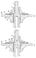
【図1】(a)は本発明の第1の実施形態の要部断面図、(b)は(a)の様態から入力側ディスクが軸方向に移動した状態を示す断面図である。
【図2】(a)は本発明の第2の実施形態の要部断面図、(b)は本発明の第3の実施形態の要部断面図である。
【図3】従来のトロイダル型無段変速機の一例を示す断面図である。
【符号の説明】
1 入力軸
1a 段差部(第1の段差部)
2A,2B 入力側ディスク
2b,9a 段差(第2の段差部)
3A,3B 出力側ディスク
4 出力歯車
5 ニードル軸受
6 ボールスプライン
7 カム板
9 ローディングナット(ナット部材)
10 皿ばね(弾性部材)
11 パワーローラ
30 シム[0001]
BACKGROUND OF THE INVENTION
The present invention relates to a toroidal-type continuously variable transmission that can be used in a transmission for an automobile or the like.
[0002]
[Prior art]
FIG. 3 shows an example of a conventional toroidal continuously variable transmission that can be used as a transmission for an automobile. This toroidal type continuously variable transmission is a so-called double cavity type toroidal type continuously variable transmission for high torque, and two
[0003]
The input shaft 1 is rotationally driven by a
[0004]
The output side disks 3A and 3B are supported rotatably about the axis O of the input shaft 1 by
[0005]
A
[0006]
Therefore, in the continuously variable transmission configured as described above, when a rotational force is input from the
[0007]
By the way, power transmission in such a toroidal continuously variable transmission is performed by pressing oil between the
[0008]
However, in order to transmit power, it is necessary to generate a certain pressing force. Therefore, when the input torque is small, a necessary pressing force cannot be obtained only by the loading cam mechanism, and power cannot be transmitted. Therefore, the preload applying device described above is used so that power can be transmitted even when the torque is small.
[0009]
As described above, the preload applying device is constituted by the
[0010]
In such a preload applying device, when the
[0011]
In relation to such a problem, Japanese Patent Laid-Open No. 2000-74167 discloses a structure in which a
[0012]
Japanese Patent Application Laid-Open No. 2000-18351 discloses a structure in which a disc spring is installed on the back side of a front-side input-side disk to apply a preload. When preload adjustment is performed by installing a disc spring on the front side in this way, assembly is simplified and effective if a shim is inserted into the rear surface of the input disk on the rear side to perform position adjustment.
[0013]
[Problems to be solved by the invention]
However, in the structure disclosed in Japanese Patent Application Laid-Open No. 2000-74167 (the structure in FIG. 3 is the same), the supporting
[0014]
On the other hand, when a shim is provided in the structure disclosed in Japanese Patent Laid-Open No. 2000-18351, unless the shim position is restricted to be concentric with the input shaft, the step provided on the input shaft and the input side disk This will cause a situation where a shim is sandwiched between the back and the back. For this reason, a problem is caused in the preload adjustment of the disc spring, causing slippage due to insufficient preload and reduction in efficiency due to excessive preload.
[0015]
The present invention has been made by paying attention to the above circumstances, and has a simple structure with excellent reliability and durability that can ensure the concentricity between the input shaft and the disc spring or shim and can reliably perform the preload adjustment. An object is to provide a toroidal type continuously variable transmission.
[0016]
[Means for Solving the Problems]
In order to solve the above problems, the invention described in claim 1 includes an input shaft to which rotational force is input, an input side disk coupled to the input shaft and rotating integrally with the input shaft, and the input side An output side disk in which the rotational force of the disk is transmitted via the power roller, a pressing device that applies a pressing force to the contact portion between each input / output side disk and the power roller, and a preload that supplements the pressing force of the pressing device In the toroidal-type continuously variable transmission including the device, the preload applying device includes a nut member fastened to the input shaft and an elastic member for applying preload, and the nut member is provided on the input shaft. It is positioned abuts against the axially first stepped portion, respectively on the back of the nut member and the input side disk, a second step portion extending in parallel to form the input shaft and concentrically With preload provided The elastic member of the apparatus, while being supported by the outer peripheral portion of the second step of both the nut member and the input-side disks, is interposed between the nut member and the input side disk, the When the nut member is positioned at the first step portion of the input shaft, a gap smaller than the initial gap of the elastic member is formed between the input side disk and the nut member. It is characterized by.
[0017]
According to the first aspect of the present invention, since the nut member is abutted against the first step portion provided on the input shaft and is positioned in the axial direction, it is easy to confirm after the nut member is tightened. Thus, the reliability of the tightening operation can be improved, and the gap between the elastic members necessary for the design can be set with high accuracy. The second step portion are respectively provided on the back surface of the nut member and the input side disk, the elastic member of the preload application device, supported by the outer peripheral portion of the second step of both the nut member and the input side disk being, because it is interposed between the input side disk and the nut member, it is possible to input shaft and concentrically supporting the elastic member, therefore, there is no possibility that malfunction of the position of the elastic member occurs Assembling performance is improved. As a result, the assembly work time can be reduced, and as a result, the cost can be reduced. Thus, if it can be assembled reliably, the reliability of the toroidal-type continuously variable transmission can be improved without the risk of causing insufficient preload or excessive preload. Moreover, since such an effect can be realized only by providing a simple step, the finished surface and the number of parts are small, and the manufacturing cost can be kept low.
[0019]
Further , even when the input side disk moves in the axial direction at the time of torque load, the movement is absorbed by the gap, and the end face of the input side disk and the end face of the nut member come into contact with each other and the nut member causes the input side disk to move. Since the movement is restricted, the elastic member is not crushed. Therefore, the stress of the elastic member due to deformation can be suppressed, and deterioration of the elastic member can be prevented. Further, since the shim can be disposed between the input side disk and the nut member due to the existence of the gap, the gap of the elastic member can be easily adjusted by the shim.
[0021]
Further , even when the input side disk moves in the axial direction at the time of torque load, the elastic member does not deform beyond the amount of the initial gap due to the movement. Therefore, the stress of the elastic member due to deformation can be suppressed, and deterioration of the elastic member can be prevented.
[0022]
DETAILED DESCRIPTION OF THE INVENTION
Hereinafter, embodiments of the present invention will be described with reference to the drawings. The feature of the present invention is that the form of the preload application device has been improved, and other configurations and operations are the same as the conventional configurations and operations described above. Therefore, only the features of the present invention will be described below. Reference is made to the other portions, and the same reference numerals as those in FIG.
[0023]
FIG. 1 shows a first embodiment of the present invention in which a disc spring is installed on the back surface of an input side disk. As shown in FIG. 1 (a), the back surface of the
[0024]
As described above, in the configuration of the present embodiment, the
[0025]
Further, in the configuration of the present embodiment, the
[0026]
Thus, if the
[0027]
Further, in the configuration of the present embodiment, when the
[0028]
In this way, if a gap S1 can be formed between the
[0029]
FIG. 2 (a) shows a second embodiment of the present invention in which shims are installed on the back side of the input side disk. As shown in the drawing, a back surface of the
[0030]
Further, the
[0031]
Thus, in the configuration of the present embodiment, the
[0032]
Further, in the configuration of the present embodiment, when the
[0033]
FIG. 2B shows a third embodiment of the present invention in which shims are installed on the back surface of the input side disk. In this embodiment, a
[0034]
【The invention's effect】
As described above, according to the first aspect of the present invention, the nut member is abutted against the first step portion provided on the input shaft and is positioned in the axial direction. The later confirmation becomes easy, the reliability of the tightening operation can be improved, and the gap between the elastic members required for the design can be set with high accuracy. The second step portion are respectively provided on the back surface of the nut member and the input side disk, the elastic member of the preload application device, supported by the outer peripheral portion of the second step of both the nut member and the input side disk being, because it is interposed between the input side disk and the nut member, it is possible to input shaft and concentrically supporting the elastic member, therefore, there is no possibility that malfunction of the position of the elastic member occurs Assembling performance is improved. As a result, the assembly work time can be reduced, and as a result, the cost can be reduced. Thus, if it can be assembled reliably, the reliability of the toroidal-type continuously variable transmission can be improved without the risk of causing insufficient preload or excessive preload. Moreover, since such an effect can be realized only by providing a simple step, the finished surface and the number of parts are small, and the manufacturing cost can be kept low.
[0035]
Also , even when the input side disk moves in the axial direction when torque is applied, the movement is absorbed by the gap, and the end face of the input side disk and the end face of the nut member come into contact with each other so that the input side disk moves by the nut member. Therefore, the elastic member is not crushed. Therefore, the stress of the elastic member due to deformation can be suppressed, and deterioration of the elastic member can be prevented. Further, since the shim can be disposed between the input side disk and the nut member due to the existence of the gap, the gap of the elastic member can be easily adjusted by the shim.
[0036]
Further , even when the input side disk moves in the axial direction at the time of torque load, the elastic member does not deform beyond the amount of the initial gap due to the movement. Therefore, the stress of the elastic member due to deformation can be suppressed, and deterioration of the elastic member can be prevented.
[Brief description of the drawings]
FIG. 1A is a cross-sectional view of a main part of a first embodiment of the present invention, and FIG. 1B is a cross-sectional view showing a state where an input side disk has moved in an axial direction from the state of FIG.
2A is a cross-sectional view of a main part of a second embodiment of the present invention, and FIG. 2B is a cross-sectional view of a main part of a third embodiment of the present invention.
FIG. 3 is a cross-sectional view showing an example of a conventional toroidal continuously variable transmission.
[Explanation of symbols]
1
2A, 2B
3A, 3B Output side disk 4
10 Disc spring (elastic member)
11
Claims (1)
前記予圧付与装置は、入力軸に締結されたナット部材と、予圧を付与する弾性部材とを有し、
前記ナット部材は、前記入力軸に設けられた第1の段差部に当接されて軸方向に位置決めされ、
前記ナット部材および前記入力側ディスクの背面にはそれぞれ、前記入力軸と同心を成して平行に延びる第2の段差部が設けられ、
前記予圧付与装置の前記弾性部材は、前記ナット部材および前記入力側ディスクの両方の前記第2の段差部の外周部によって支持されつつ、前記入力側ディスクと前記ナット部材との間に介挿され、
前記ナット部材が前記入力軸の第1の段差部で位置決めされた際に、前記入力側ディスクと前記ナット部材との間には、前記弾性部材の初期隙間よりも小さい隙間が形成されるようになっていることを特徴とするトロイダル型無段変速機。An input shaft to which rotational force is input, an input side disk coupled to the input shaft and rotating integrally with the input shaft, an output side disk to which the rotational force of the input side disk is transmitted via a power roller, In a toroidal continuously variable transmission including a pressing device that applies a pressing force to the contact portion between each input / output disk and a power roller, and a preload applying device that compensates the pressing force of the pressing device,
The preload applying device includes a nut member fastened to an input shaft, and an elastic member for applying preload,
The nut member is abutted against a first step provided on the input shaft and is positioned in the axial direction;
Each of the nut member and the back surface of the input side disk is provided with a second step portion that is concentric with the input shaft and extends in parallel .
The elastic member of the preload application device, while being supported by the outer peripheral portion of the second step of both the nut member and the input-side disks, interposed between the nut member and the input side disk It is,
When the nut member is positioned at the first step portion of the input shaft, a gap smaller than the initial gap of the elastic member is formed between the input side disk and the nut member. toroidal type continuously variable transmission, characterized in that it it.
Priority Applications (1)
| Application Number | Priority Date | Filing Date | Title |
|---|---|---|---|
| JP2001329088A JP3758148B2 (en) | 2001-10-26 | 2001-10-26 | Toroidal continuously variable transmission |
Applications Claiming Priority (1)
| Application Number | Priority Date | Filing Date | Title |
|---|---|---|---|
| JP2001329088A JP3758148B2 (en) | 2001-10-26 | 2001-10-26 | Toroidal continuously variable transmission |
Publications (3)
| Publication Number | Publication Date |
|---|---|
| JP2003130161A JP2003130161A (en) | 2003-05-08 |
| JP2003130161A5 JP2003130161A5 (en) | 2005-06-09 |
| JP3758148B2 true JP3758148B2 (en) | 2006-03-22 |
Family
ID=19145045
Family Applications (1)
| Application Number | Title | Priority Date | Filing Date |
|---|---|---|---|
| JP2001329088A Expired - Fee Related JP3758148B2 (en) | 2001-10-26 | 2001-10-26 | Toroidal continuously variable transmission |
Country Status (1)
| Country | Link |
|---|---|
| JP (1) | JP3758148B2 (en) |
Families Citing this family (1)
| Publication number | Priority date | Publication date | Assignee | Title |
|---|---|---|---|---|
| JPWO2010073557A1 (en) * | 2008-12-26 | 2012-06-07 | アイシン・エィ・ダブリュ株式会社 | Friction wheel type continuously variable transmission |
-
2001
- 2001-10-26 JP JP2001329088A patent/JP3758148B2/en not_active Expired - Fee Related
Also Published As
| Publication number | Publication date |
|---|---|
| JP2003130161A (en) | 2003-05-08 |
Similar Documents
| Publication | Publication Date | Title |
|---|---|---|
| JP4372997B2 (en) | Variator transmission | |
| JP4196831B2 (en) | Electric power steering device | |
| JP4196630B2 (en) | Telescopic shaft for vehicle steering | |
| JP4196642B2 (en) | Telescopic shaft for vehicle steering | |
| JP4254194B2 (en) | Telescopic shaft for vehicle steering | |
| WO2008093861A1 (en) | Electric power steering device | |
| WO2018092681A1 (en) | Toroidal continuously variable transmission | |
| EP1657137B1 (en) | Steering apparatus | |
| JPH02120548A (en) | Toroidal type continuously variable transmission | |
| JP3758148B2 (en) | Toroidal continuously variable transmission | |
| JP3760987B2 (en) | Toroidal type continuously variable transmission and method of assembling the same | |
| JP3734159B2 (en) | Preloading jig for toroidal type continuously variable transmission and assembly method using the jig | |
| JP3292153B2 (en) | Toroidal type continuously variable transmission | |
| EP4047237B1 (en) | Clutch structure | |
| JP4326414B2 (en) | Torque limiter device manufacturing method and torque limiter device assembly method | |
| JP4096519B2 (en) | Planetary gear unit | |
| WO2017221484A1 (en) | Damper device | |
| JP3758149B2 (en) | Toroidal continuously variable transmission | |
| JP3587553B2 (en) | Vibration prevention device | |
| JP4055255B2 (en) | Toroidal type continuously variable transmission | |
| JP3632114B2 (en) | Roller transmission device and electric power steering device | |
| JP4725768B2 (en) | Toroidal continuously variable transmission | |
| JP2005233235A (en) | Toroidal type continuously variable transmission | |
| JPH06280957A (en) | Continuously variable transmission with friction wheel | |
| JP2940375B2 (en) | Friction wheel type continuously variable transmission |
Legal Events
| Date | Code | Title | Description |
|---|---|---|---|
| A521 | Written amendment |
Free format text: JAPANESE INTERMEDIATE CODE: A523 Effective date: 20040906 |
|
| A621 | Written request for application examination |
Free format text: JAPANESE INTERMEDIATE CODE: A621 Effective date: 20040906 |
|
| A131 | Notification of reasons for refusal |
Free format text: JAPANESE INTERMEDIATE CODE: A131 Effective date: 20050930 |
|
| A521 | Written amendment |
Free format text: JAPANESE INTERMEDIATE CODE: A523 Effective date: 20051124 |
|
| TRDD | Decision of grant or rejection written | ||
| A01 | Written decision to grant a patent or to grant a registration (utility model) |
Free format text: JAPANESE INTERMEDIATE CODE: A01 Effective date: 20051209 |
|
| A61 | First payment of annual fees (during grant procedure) |
Free format text: JAPANESE INTERMEDIATE CODE: A61 Effective date: 20051222 |
|
| R150 | Certificate of patent or registration of utility model |
Free format text: JAPANESE INTERMEDIATE CODE: R150 |
|
| FPAY | Renewal fee payment (event date is renewal date of database) |
Free format text: PAYMENT UNTIL: 20100113 Year of fee payment: 4 |
|
| FPAY | Renewal fee payment (event date is renewal date of database) |
Free format text: PAYMENT UNTIL: 20100113 Year of fee payment: 4 |
|
| FPAY | Renewal fee payment (event date is renewal date of database) |
Free format text: PAYMENT UNTIL: 20110113 Year of fee payment: 5 |
|
| FPAY | Renewal fee payment (event date is renewal date of database) |
Free format text: PAYMENT UNTIL: 20120113 Year of fee payment: 6 |
|
| FPAY | Renewal fee payment (event date is renewal date of database) |
Free format text: PAYMENT UNTIL: 20130113 Year of fee payment: 7 |
|
| FPAY | Renewal fee payment (event date is renewal date of database) |
Free format text: PAYMENT UNTIL: 20130113 Year of fee payment: 7 |
|
| FPAY | Renewal fee payment (event date is renewal date of database) |
Free format text: PAYMENT UNTIL: 20140113 Year of fee payment: 8 |
|
| LAPS | Cancellation because of no payment of annual fees |