JP3758145B2 - Trimming type with scrap cutting blade - Google Patents
Trimming type with scrap cutting blade Download PDFInfo
- Publication number
- JP3758145B2 JP3758145B2 JP2001321453A JP2001321453A JP3758145B2 JP 3758145 B2 JP3758145 B2 JP 3758145B2 JP 2001321453 A JP2001321453 A JP 2001321453A JP 2001321453 A JP2001321453 A JP 2001321453A JP 3758145 B2 JP3758145 B2 JP 3758145B2
- Authority
- JP
- Japan
- Prior art keywords
- blade
- scrap
- cutting blade
- scrap cutting
- trimming
- Prior art date
- Legal status (The legal status is an assumption and is not a legal conclusion. Google has not performed a legal analysis and makes no representation as to the accuracy of the status listed.)
- Expired - Fee Related
Links
Images


Description
【0001】
【発明の属する技術分野】
この発明はトリム加工のためのトリミング型に関するものであり、特に、ワークのスクラップ部を分断するための上部スクラップ分断刃と下部スクラップ分断刃とを備えたスクラップ分断刃付きトリミング型に関するものである。
【0002】
【従来の技術】
一般に、車体外板(ドア、天井、ボンネット、トランク等)や種々の外板(以下、ワークという)のプレス成形においては、ワークを一次成形した後、不用なスクラップ部を切り落として二次成形工程に供給する。スクラップ部を切り落とすためのトリミング型は、上型(ポンチホルダ)に取り付けられた上刃と、下型(ダイ)に取り付けられた下刃とで主要部が構成されており、下刃と上刃の噛み合いによってワークからスクラップ部を枠状ないしは額縁状の状態で切り落とすが、枠状あるいは額縁状のスクラップ部はその後の取り扱いが不便で、広い集積スペースを必要とする欠点がある。
【0003】
そこで、上刃と下刃にそれぞれ上部スクラップ分断刃、下部スクラップ分断刃を設け、上部スクラップ分断刃と下部スクラップ分断刃との噛み合いにより、分断のための切り込みをスクラップ部に形成し、その後のトリミングによってワークから切り落とすようにした「スクラップ分断刃付きトリミング型」(実公昭62−22268号公報)が提案されている。
図7はかかるスクラップ分断刃付きトリミング型の構造を示し、図7(a)は要部詳細斜視断面図、図7(b)及び図7(c)は図7(a)の側面図である。図7(a)〜(c)に示すように、トリミング型110の上刃111には、先行刃111aを有する上部トリミング刃111bが設けられると共に、先行刃111aと直角に交わるように上部スクラップ分断刃111cが設けられる。下刃112には、上部トリミング刃111bと上部スクラップ分断刃111cに対応させて下部トリミング刃112bと下部スクラップ分断刃112cが設けられる。下部スクラップ分断刃112cの上端面112dは、上部トリミング刃111bと下部トリミング刃112c同士の噛み合いストロークを得るため、下刃112の刃面よりも下方に位置しており、下部スクラップ分断刃112cの上端面112dの根元部には、バリ逃しのための切欠部112eが設けられる。また、前記先行刃111aには刃方向に沿って一定のシャー角が設定される。
先行刃111aの始端に直角に連なる上部スクラップ分断刃111cによりL字型の切り込みが行われると、先行刃111aは、下部トリミング刃112bと直ちに噛み合うが、下部スクラップ分断刃112cの上端面112dには先行刃111aに対応する刃がないので、スクラップ部Sは上部スクラップ分断刃111cの押圧力と、スクラップ部Sに作用する張力によって上部スクラップ分断刃111cの方向に僅かに切断される。
このような分断の形態は、「空中カット」と呼ばれており、下部スクラップ分断刃112cの上端面112dに沿う切り口は、切り裂くようにちぎれてバリが形成されるが、スクラップ部Sの分断箇所の根元側に生じたバリは、下方の切欠部112eに逃げてせん断を免れ、スクラップ部Sと一体となって切り落とされる。
【0004】
【発明が解決しようとする課題】
このように、切欠部にスクラップ部側のバリを逃してその後のせん断を防止すると、空中カット時に生じたスクラップ部のバリのワークへの付着が防止される。しかし、空中カット時の切り裂きの状態によっては、ワークに働く分力の方向と大きさによってワークに微少な位置ずれが発生したり、ワーク側に切り込みが進行することがある。
また、前記切欠部を設けると、切欠部に応力が集中してしまうため、必要な強度を得るには、高価な金属材料の使用を余儀なくされる。
この発明は前記事情に鑑みてなされたものであり、その目的は、空中カットによらずスクラップ部に切り込みを形成できるようにすることにある。
【0005】
【課題を解決するための手段】
請求項1記載の発明は、ワークのトリミングに先行してワークのスクラップ部に分断のための切り込みを形成する上部スクラップ分断刃と下部スクラップ分断刃とをトリミング型の上型と下型とに取り付けたスクラップ分断刃付きトリミング型において、前記上部スクラップ分断刃は、前記上型の外側部に、また、前記下部スクラップ分断刃は、前記下型の外側部に突出した台座の上面に取り付けられ、前記下部スクラップ分断刃は、第1の刃部と第2の刃部とに分割され、前記第1の刃部は、前記第2の刃部の一側面に設けられたガイド溝に昇降自在に且つ摺動自在に係合し、前記下部スクラップ分断刃の前記第1の刃部と前記第2の刃部の刃面を前記スクラップ部の下面に倣わせて形成すると共に、この第1の刃部を弾性体を介して昇降自在に支持させ、前記弾性体の付勢力によって前記下部スクラップ分断刃を上方側に移動させてその刃面を前記スクラップ部の下面に当接させて、前記下部スクラップ分断刃の前記第1の刃部と前記第2の刃部の刃面で前記スクラップ部の下面をスクラップ部の横断方向に且つ全幅に及んで支持した状態で前記上部スクラップ分断刃と前記下部スクラップ分断刃の前記第1の刃部と前記第2の刃部とで前記スクラップ部に前記切り込みを形成するように構成したことを特徴とするスクラップ分断刃付きトリミング型を提供するものである。
このように構成すると、ワークのスクラップ部が下部スクラップ分断刃に支持された状態で上部スクラップ分断刃と下部スクラップ分断刃によって切断されるので、バリの発生やワーク側への切り込みの進行を防止でき、ワークの位置ずれを防止することができる。このため、トリミングの加工精度が向上すると共に、バリに起因したワーク表面の痕跡をなくすことができる。
【0006】
さらに、請求項2記載の発明は、前記弾性体の初期設定荷重が前記スクラップ部の切断を可能とするように定められたスクラップ分断刃付きトリミング型を提供するものである。
このようにすると、下部スクラップ分断刃と上部スクラップ分断刃との相互干渉が防止され、上部スクラップ分断刃および下部スクラップ分断刃が保護されるので、信頼性、耐久性が向上する。
【0007】
なお、請求項1及び請求項2記載の発明において、下部スクラップ分断刃を予めスクラップ部の形状に基づいて複数に分割し、分割された各部を弾性体を介してそれぞれ昇降自在に支持させるようにしてもよい。この場合、下部スクラップ分断刃のトリミングライン側の分割部のみを弾性体を介して昇降自在としてもよい。このようにすると、刃面の成形が容易となり、メンテナンス性が向上する。
【0008】
【発明の実施の形態】
以下、添付図面を参照して本発明にかかるスクラップ分断刃付きトリミング型の一実施の形態を説明する。
【0009】
図1は本実施の形態にかかるスクラップ分断刃付きトリミング型の全体構成図である。トリミング型1の上型2及び下型3の外側部には、ワーク(一次成形品;ドロー成形品)Wのスクラップ部Sを切り落とすための上刃4と下刃5とが備えられると共に、ワークWのトリミングに先だってワークWのスクラップ部Sに分断のための切り込みを形成するための上部スクラップ分断刃6…と下部スクラップ分断刃7…とが備えられる。前記上部スクラップ分断刃6…は、上型2の外側部に、また、下部スクラップ分断刃7…は下型3の外側部から外側に突出した台座8…の上面に取り付けられる。上部スクラップ分断刃6…は、下型3に載置されているワークWのスクラップ部Sを下方に臨んでおり、また、下部スクラップ分断刃7…は、ワークWのスクラップ部Sを上方に臨んでいる。
【0010】
図2は前記上部スクラップ分断刃6および下部スクラップ分断刃7の取り付け状態を示す斜視図、図3は下部スクラップ分断刃7の構成を示す分解斜視図である。図2及び図3に示すように、上部スクラップ分断刃6には、ワークWのスクラップ部Sに切り込みを形成するための第1の刃部6aと、この第1の刃部6aによって形成された切り込みをさらにスクラップ部Sの横断方向に拡張して最終の切り込みとする第2の刃部6bとが設けられ、同様に、下部スクラップ分断刃7には、ワークWのスクラップ部Sに切り込みを形成するための第1の刃部7aと、この第1の刃部7aによって形成された切り込みをさらにスクラップ部Sの横断方向に拡張して最終の切り込みとする第2の刃部7bとが設けられる。
上部スクラップ分断刃6の第1の刃部6aと第2の刃部6bとは互いに一体に形成され、また、下部スクラップ分断刃7は、第1の刃部7aと第2の刃部7bとに分割されていて、その刃面でスクラップ部Sの下面を支持する。前記下部スクラップ分断刃7…の第1の刃部7aは、下部スクラップ分断刃7の第2の刃部7bの一側面に設けられた上下方向の直線状ガイド溝7cに昇降自在に且つ摺動自在に係合している。そして、下部スクラップ分断刃7の第1の刃部7aには、前記直線状ガイド溝7cとの対向部に上下方向の長孔7dが設けられており、座板(座金)9の孔と長孔7dとに挿入されたボルト10が直線状ガイド溝7cの底部に形成されているねじ孔7e(図3参照)と螺合している。
図3に示すように、前記ボルト10の先端部は、このボルト10の基部に対して縮径された螺子部10aとなっていて、前記ねじ孔7eと螺合するように構成されており、ボルト10の基部の長さは、前記座板9の肉厚と下部スクラップ分断刃7の第1の刃部7aの肉圧との合算値よりも僅かに大きくなっている。このため、ねじ孔7eに図2に示すようにボルト10が締結された状態では、第1の刃部7aと直線状ガイド溝7cの溝底との間に僅かなクリアランスが形成され、このクリアランスによって第1の刃部7aの昇降が可能となる。
【0011】
そして、下部スクラップ分断刃7の第1の刃部7aおよび第2の刃部7bの刃面は、スクラップ部Sの下面をスクラップ部Sの横断方向に且つ全幅に及んで支持するために、スクラップ部Sの下面に倣わせて形成され、下部スクラップ分断刃7の第1の刃部7aの下面と前記台座8の上面との間に弾性体11が介設される。
前記弾性体11は、所定のゴム硬度で所定のゴム弾性を有するウレタンゴム、クロロプレンゴム等のゴム、又は、圧縮コイルばね、板ばねなどのばね、あるいは、これらの複合部品によって構成されており(図示例では圧縮コイルばね)、その付勢力で下部スクラップ分断刃7の第1の刃部7aを上方へ移動させて、スクラップ部Sの下面に刃面を当接させ、この状態でスクラップ部Sを支持するようになっている。そして、弾性体11の初期設定荷重(セットフォース)は、下部スクラップ分断刃7の第1の刃部7aと上部スクラップ分断刃6の第1の刃部6aで前記スクラップ部Sの下面を支持しながらこの状態でスクラップ部Sに横断方向の切り込みを形成できるように設定されると共に、上部スクラップ分断刃6の第1の刃部6aと下部スクラップ分断刃7の第1の刃部7aとの噛み合いを保持させながら上部スクラップ分断刃6の第2の刃部6bと下部スクラップ分断刃7の第2の刃部7bで前記スクラップ部Sに切り込みを形成できるように設定される。
このように、弾性体11の初期設定荷重を決定すると、前記した上型2と下型3によって、スクラップ部S全体がワークWから切り離される際に、上部スクラップ分断刃6の第1の刃部6aと下部スクラップ分断刃7の第1の刃部7aとの相互干渉が防止されるので、干渉に起因した損傷が防止される。
【0012】
なお、図2及び図3において、前記下部スクラップ分断刃7の第1の刃部7aには、前記弾性体11による最大上昇位置を規制するため、下部に鍔状のストップ部7fが設けられ、下部スクラップ分断刃7の第2の刃部7bの下部には、前記した鍔状のストッパ7fを最大上昇位置に規制するための制止面部7gが設けられる。また、前記下部スクラップ分断刃7の第1の刃部7aの下面には、図3に示すように、前記弾性体11としての圧縮コイルばねをガイドするためのガイド部7hが設けられる。さらに、下部スクラップ分断刃7の第2の刃部7bの上面には、ワークWの位置決めのためスクラップ部Sに成形されている凸条部S1を係合させるための係合部7iが設けられる。
【0013】
次に、図1、図4、図5及び図6を参照して前記トリミング型1によるワークWのトリミング工程を説明する。
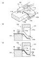
図1に示すように、下型3にワークWを載置し、スクラップ部Sの凸条部S1を下部スクラップ分断刃7の係合部7iに係合させてワークWのセットを完了する。続いて、上型2を下型3側に下降させる。上部スクラップ分断刃6が上型2と一体となって下降すると、図4に示すように、上部スクラップ分断刃6の第1の刃部6aと下部スクラップ分断刃7の第1の刃部7aとで、切り込みC1が形成される。切り込みC1は、上部スクラップ分断刃6の下降に連れてスクラップ部Sの横断方向に延びていく。上型2の下降が進み、上部スクラップ分断刃6の第1の刃部6aと下部スクラップ分断刃7の第1の刃部7bによる切り込みが完了すると、次に、上部スクラップ分断刃6の第2の刃部6bと下部スクラップ分断刃7の第2の刃部7bとでスクラップ部Sの横断方向に切り込みが広げられ上型2の上刃4と下型3の下刃5とがワークWのトリミングライン(図示せず)に接したとき、最終的な切り込みC2が形成される(図6(a)→図6(b)参照)。
このとき、上部スクラップ分断刃6の第1の刃部6aと下部スクラップ分断刃7の第1の刃部7aとの間の相互干渉は前記弾性体11の緩衝作用により防止される。
上部スクラップ分断刃6の第2の刃部6b及び下部スクラップ分断刃7の第2の刃部7bにより切り込みが完了した後は、図5に示すように、上刃4と下刃5との噛み合いによってスクラップ部Sが切り落とされる(図6(c)→図6(d)参照)。
【0014】
このように、本発明の一実施の形態にかかるトリミング型1によれば、スクラップ部Sを切り裂いて切り込みを形成する従来の空中カットとは異なって、下部スクラップ分断刃7の刃面でスクラップ部Sを支持し、この状態を保持して切り込みを形成するので、ワークWの位置ずれや、ワーク側への切り込みの発生がない。また、バリの形成が防止され、バリに起因する切粉の発生も防止されるので、次の成形工程での切粉による痕跡の発生を防止することができる。
【0015】
なお、本実施の一形態の説明においては、スクラップ部Sの複雑な形状に対応するため、下部スクラップ分断刃7の第1の刃部7aを第2の刃部7bの一側面に弾性体11を介して昇降自在に設けた例を示したが、下部スクラップ分断刃7の第2の刃部7bも前記弾性体11を介して昇降自在としてもよい。もちろん、スクラップ部Sの形状が単純で下部スクラップ分断刃7を複数に分割する必要がない場合は、スクラップ部Sの下面に倣わせて下部スクラップ分断刃7の刃面を形成し、下部スクラップ分断刃7全体を前記弾性体11を介して昇降自在に支持してもよい。このようにすると、廉価なトリミング型1とすることができる。
【0016】
また、本発明の一実施の形態の説明においては、下部スクラップ分断刃7の第2の刃部7bを弾性体11を介して昇降自在に設けるという説明をしたが、下部スクラップ分断刃7全体を固定としてその代わりに上部スクラップ分断刃6を弾性体11を介して昇降自在としてもよい。この場合、下部スクラップ分断刃7と同様に、上部スクラップ分断刃6の第2の刃部6bに対して第1の刃部6aを弾性体11を介して昇降自在としてもよい。さらに、上部スクラップ分断刃6の刃面を、スクラップ部Sの上面に倣わせて形成してもよい。
【0017】
【発明の効果】
以上、説明したことから明らかなようにこの発明によれば次の如き優れた効果を発揮する。
請求項1記載の発明によれば、スクラップ部を切り裂いて切り込みを形成する従来の空中カットとは異なって、下部スクラップ分断刃の刃面でスクラップ部を支持した状態で上部スクラップ分断刃と下部スクラップ分断刃との切断によってスクラップ部に切り込みを形成するので、切り裂きに起因するワークの位置ずれや、ワーク側への切り込みの進行を防止することができる。また、バリの形成が防止され、バリに起因する切粉の発生が防止されるので、次の成形工程での切粉の付着による痕跡の発生を防止することができる。さらに、バリを逃すための切欠部を必要としないので、下部スクラップ分断刃の強度を実質的に向上することができる。
請求項2記載の発明によれば、下部スクラップ分断刃と上部スクラップ分断刃との相互干渉が防止されるので、上部スクラップ分断刃および下部スクラップ分断刃の信頼性及び耐久性が向上する。
【図面の簡単な説明】
【図1】本発明の一実施の形態にかかるスクラップ分断刃付きトリミング型の全体構成を示す斜視図である。
【図2】本発明の一実施の形態にかかる上部スクラップ分断刃および下部スクラップ分断刃を示す斜視図である。
【図3】本発明の一実施の形態にかかる下部スクラップ分断刃の構成を示す分解斜視図である。
【図4】本発明の一実施の形態にかかるワークのトリミング工程の斜視図であり、スクラップ部に切り込みを形成した状態を示す解説斜視図である。
【図5】本発明の一実施の形態にかかるワークのトリミング工程の斜視図であり、トリミングにより、スクラップ部を切り落とした状態を示す斜視図である。
【図6】本発明の一実施の形態にかかるワークのトリミング工程の平面図であり、図6(a)はトリミング前の状態を示す平面図、図6(b)はスクラップ部に切り込みを形成した状態を示す平面図、図6(c)はトリミングによりワークからスクラップ部を切り離す状態を示す平面図、図6(d)はワークからスクラップ部が切り離された状態を示す平面図である。
【図7】従来のスクラップ分断刃付きトリミング型の構造を示し、図7(a)は要部詳細斜視断面図、図7(b)及び図7(c)は図7(a)の側面図である。
【符号の説明】
2 上型
3 下型
6 上部スクラップ分断刃
7 下部スクラップ分断刃
11 弾性体
C1 切り込み
W ワーク
S スクラップ部[0001]
BACKGROUND OF THE INVENTION
The present invention relates to a trimming die for trim processing, and more particularly to a trimming die with a scrap cutting blade provided with an upper scrap cutting blade and a lower scrap cutting blade for cutting a scrap portion of a workpiece.
[0002]
[Prior art]
In general, in press molding of car body skins (doors, ceilings, bonnets, trunks, etc.) and various skins (hereinafter referred to as workpieces), after the workpieces have been primary molded, unnecessary scrap parts are cut off and the secondary molding process To supply. The trimming die for cutting off the scrap part consists of an upper blade attached to the upper die (punch holder) and a lower blade attached to the lower die (die). The scrap part is cut off from the work in a frame-like or frame-like state by meshing, but the frame-like or frame-like scrap part is inconvenient to handle and has a drawback of requiring a large accumulation space.
[0003]
Therefore, an upper scrap cutting blade and a lower scrap cutting blade are provided on the upper blade and the lower blade, respectively, and an incision for cutting is formed in the scrap portion by meshing with the upper scrap cutting blade and the lower scrap cutting blade, followed by trimming. "Trimming type with scrap cutting blades" (Japanese Utility Model Publication No. 62-22268) is proposed.
FIG. 7 shows the structure of such a trimming die with a scrap cutting blade, FIG. 7 (a) is a detailed perspective sectional view of the main part, and FIGS. 7 (b) and 7 (c) are side views of FIG. 7 (a). . As shown in FIGS. 7A to 7C, an
When L-shaped cutting is performed by the upper
Such a form of division is called “aerial cut”, and the cut along the
[0004]
[Problems to be solved by the invention]
As described above, if the burr on the scrap part side is missed in the notch and the subsequent shearing is prevented, adhesion of the burr of the scrap to the work caused during the air cut is prevented. However, depending on the state of tearing during aerial cutting, the workpiece may be slightly misaligned or cut into the workpiece depending on the direction and magnitude of the component force acting on the workpiece.
In addition, when the cutout portion is provided, stress concentrates on the cutout portion, and thus an expensive metal material is inevitably used to obtain a required strength.
This invention is made in view of the said situation, The objective is to enable it to form a notch in a scrap part irrespective of aerial cutting.
[0005]
[Means for Solving the Problems]
According to the first aspect of the present invention, an upper scrap cutting blade and a lower scrap cutting blade for forming a cut for cutting in the scrap portion of the work prior to the trimming of the work are attached to the upper die and the lower die of the trimming die. In the trimming die with scrap cutting blade, the upper scrap cutting blade is attached to the outer portion of the upper die, and the lower scrap cutting blade is attached to the upper surface of the pedestal protruding to the outer portion of the lower die, The lower scrap cutting blade is divided into a first blade portion and a second blade portion, and the first blade portion is movable up and down in a guide groove provided on one side surface of the second blade portion, and The first blade portion is slidably engaged to form the first blade portion of the lower scrap cutting blade and the blade surface of the second blade portion following the lower surface of the scrap portion. Elevating through an elastic body Is supported on the stationary, the blade surface is brought into contact with the lower surface of the scrap portion is moved upward the lower scrap cutting blade by the urging force of the elastic body, said first blade of said lower scrap cutting blade The first scrap of the upper scrap cutting blade and the lower scrap cutting blade in a state where the lower surface of the scrap portion is supported across the entire width of the scrap portion by the blade surface of the portion and the second blade portion . The present invention provides a trimming die with a scrap cutting blade, characterized in that the cut portion is formed in the scrap portion by the blade portion and the second blade portion .
With this configuration, since the scrap part of the workpiece is supported by the lower scrap cutting blade and is cut by the upper scrap cutting blade and the lower scrap cutting blade, it is possible to prevent the occurrence of burrs and the progress of cutting to the workpiece side. Therefore, it is possible to prevent the workpiece from being displaced. For this reason, the trimming processing accuracy can be improved and traces of the workpiece surface due to burrs can be eliminated.
[0006]
Furthermore, the invention according to
If it does in this way, mutual interference with a lower scrap parting blade and an upper scrap parting blade is prevented, and since an upper scrap parting blade and a lower scrap parting blade are protected, reliability and durability improve.
[0007]
In the first and second aspects of the invention, the lower scrap cutting blade is divided into a plurality of pieces in advance based on the shape of the scrap portion, and each of the divided portions is supported so as to be movable up and down via an elastic body. May be. In this case, only the division part on the trimming line side of the lower scrap cutting blade may be freely raised and lowered via the elastic body. If it does in this way, shaping of a blade face will become easy and maintenance nature will improve.
[0008]
DETAILED DESCRIPTION OF THE INVENTION
Hereinafter, an embodiment of a trimming die with a scrap cutting blade according to the present invention will be described with reference to the accompanying drawings.
[0009]
FIG. 1 is an overall configuration diagram of a trimming die with a scrap cutting blade according to the present embodiment. On the outer side of the
[0010]
FIG. 2 is a perspective view showing how the upper
The
As shown in FIG. 3, the tip of the
[0011]
The blade surfaces of the
The
As described above, when the initial set load of the
[0012]
2 and 3, the
[0013]
Next, the trimming process of the workpiece W by the trimming die 1 will be described with reference to FIGS. 1, 4, 5, and 6. FIG.
As shown in FIG. 1, the workpiece W is placed on the
At this time, mutual interference between the
After the cutting is completed by the
[0014]
As described above, according to the trimming die 1 according to the embodiment of the present invention, unlike the conventional aerial cut in which the scrap portion S is cut and the cut is formed, the scrap portion is formed on the blade surface of the lower
[0015]
In the description of the present embodiment, in order to cope with the complicated shape of the scrap portion S, the
[0016]
In the description of the embodiment of the present invention, the
[0017]
【The invention's effect】
As is apparent from the above description, the present invention exhibits the following excellent effects.
According to the first aspect of the present invention, unlike the conventional aerial cut in which the scrap portion is cut to form a cut, the upper scrap cutting blade and the lower scrap are supported with the scrap portion supported by the blade surface of the lower scrap cutting blade. Since the notch is formed in the scrap portion by cutting with the cutting blade, it is possible to prevent the position shift of the workpiece caused by the tearing and the progress of the incision to the workpiece side. Moreover, since the formation of burrs is prevented and the generation of chips due to burrs is prevented, the generation of traces due to the adhesion of chips in the next molding step can be prevented. Furthermore, since the notch part for missing a burr | flash is not required, the intensity | strength of a lower scrap parting blade can be improved substantially.
According to the invention described in
[Brief description of the drawings]
FIG. 1 is a perspective view showing an overall configuration of a trimming die with a scrap cutting blade according to an embodiment of the present invention.
FIG. 2 is a perspective view showing an upper scrap cutting blade and a lower scrap cutting blade according to an embodiment of the present invention.
FIG. 3 is an exploded perspective view showing a configuration of a lower scrap cutting blade according to an embodiment of the present invention.
FIG. 4 is a perspective view of a workpiece trimming process according to an embodiment of the present invention, and is an explanatory perspective view showing a state where a cut is formed in a scrap portion.
FIG. 5 is a perspective view of a workpiece trimming process according to an embodiment of the present invention, and is a perspective view showing a state in which a scrap portion is cut off by trimming.
6A is a plan view of a workpiece trimming process according to an embodiment of the present invention, FIG. 6A is a plan view showing a state before trimming, and FIG. 6B is a cut portion formed in a scrap portion; FIG. 6C is a plan view showing a state where the scrap part is separated from the work by trimming, and FIG. 6D is a plan view showing a state where the scrap part is separated from the work.
7 shows the structure of a conventional trimming die with a scrap cutting blade, FIG. 7 (a) is a detailed perspective sectional view of the main part, and FIGS. 7 (b) and 7 (c) are side views of FIG. 7 (a). It is.
[Explanation of symbols]
2 Upper die 3 Lower die 6 Upper
Claims (2)
前記上部スクラップ分断刃は、前記上型の外側部に、また、前記下部スクラップ分断刃は、前記下型の外側部に突出した台座の上面に取り付けられ、
前記下部スクラップ分断刃は、第1の刃部と第2の刃部とに分割され、前記第1の刃部は、前記第2の刃部の一側面に設けられたガイド溝に昇降自在に且つ摺動自在に係合し、
前記下部スクラップ分断刃の前記第1の刃部と前記第2の刃部の刃面を前記スクラップ部の下面に倣わせて形成すると共に、この第1の刃部を弾性体を介して昇降自在に支持させ、前記弾性体の付勢力によって前記下部スクラップ分断刃を上方側に移動させてその刃面を前記スクラップ部の下面に当接させて、前記下部スクラップ分断刃の前記第1の刃部と前記第2の刃部の刃面で前記スクラップ部の下面をスクラップ部の横断方向に且つ全幅に及んで支持した状態で前記上部スクラップ分断刃と前記下部スクラップ分断刃の前記第1の刃部と前記第2の刃部とで前記スクラップ部に前記切り込みを形成するように構成したことを特徴とするスクラップ分断刃付きトリミング型。In a trimming die with scrap cutting blades, in which an upper scrap cutting blade and a lower scrap cutting blade are formed on the upper die and lower die of the trimming die to form a notch for cutting in the scrap portion of the workpiece prior to workpiece trimming. ,
The upper scrap cutting blade is attached to the outer portion of the upper mold, and the lower scrap cutting blade is attached to the upper surface of the pedestal protruding to the outer portion of the lower mold,
The lower scrap cutting blade is divided into a first blade portion and a second blade portion, and the first blade portion can be raised and lowered freely in a guide groove provided on one side surface of the second blade portion. And slidably engaged,
The first blade portion of the lower scrap cutting blade and the blade surface of the second blade portion are formed to follow the lower surface of the scrap portion, and the first blade portion can be raised and lowered via an elastic body. The lower scrap cutting blade is moved upward by the urging force of the elastic body, and the blade surface is brought into contact with the lower surface of the scrap portion, whereby the first blade portion of the lower scrap cutting blade said first blade of said upper scrap cutting blade and the lower scrap cutting blade in a state in which said lower surface of said scrap portion in the blade surface of the second blade portion to and supported span the entire width in the transverse direction of the scrap portion and A trimming die with a scrap cutting blade, characterized in that the cut is formed in the scrap portion by the portion and the second blade portion .
Priority Applications (1)
| Application Number | Priority Date | Filing Date | Title |
|---|---|---|---|
| JP2001321453A JP3758145B2 (en) | 2001-10-19 | 2001-10-19 | Trimming type with scrap cutting blade |
Applications Claiming Priority (1)
| Application Number | Priority Date | Filing Date | Title |
|---|---|---|---|
| JP2001321453A JP3758145B2 (en) | 2001-10-19 | 2001-10-19 | Trimming type with scrap cutting blade |
Publications (2)
| Publication Number | Publication Date |
|---|---|
| JP2003126926A JP2003126926A (en) | 2003-05-08 |
| JP3758145B2 true JP3758145B2 (en) | 2006-03-22 |
Family
ID=19138669
Family Applications (1)
| Application Number | Title | Priority Date | Filing Date |
|---|---|---|---|
| JP2001321453A Expired - Fee Related JP3758145B2 (en) | 2001-10-19 | 2001-10-19 | Trimming type with scrap cutting blade |
Country Status (1)
| Country | Link |
|---|---|
| JP (1) | JP3758145B2 (en) |
Families Citing this family (4)
| Publication number | Priority date | Publication date | Assignee | Title |
|---|---|---|---|---|
| JP4799828B2 (en) * | 2004-03-30 | 2011-10-26 | プレス工業株式会社 | Punching device |
| JP5018040B2 (en) * | 2006-11-24 | 2012-09-05 | オイレス工業株式会社 | Trimming press processing equipment |
| CN114433691A (en) * | 2021-11-29 | 2022-05-06 | 江苏蓝图机械制造有限公司 | Precise and rapid forming process and device for engineering machinery cab door |
| CN117000863B (en) * | 2023-10-07 | 2023-12-08 | 常州达亚汽车零部件有限公司 | High-precision automobile panel trimming die and automatic stamping equipment applying same |
-
2001
- 2001-10-19 JP JP2001321453A patent/JP3758145B2/en not_active Expired - Fee Related
Also Published As
| Publication number | Publication date |
|---|---|
| JP2003126926A (en) | 2003-05-08 |
Similar Documents
| Publication | Publication Date | Title |
|---|---|---|
| JP3653793B2 (en) | Press working mold and press working method | |
| JP4279532B2 (en) | Mold apparatus and lower mold for use in processing method of molded product | |
| US20100199739A1 (en) | Interchangeable spring loaded scrap cutter | |
| JP2611128B2 (en) | Cutting die for follow-up cutting | |
| CN111819053B (en) | Die cutting tool and method for cutting metal sheets | |
| JP3758145B2 (en) | Trimming type with scrap cutting blade | |
| CN206104645U (en) | Deburring area cut -out press mechanism | |
| JP2006205234A (en) | Burring dies and burring method | |
| CN211027756U (en) | Bending and cutting integrated mechanism on progressive die | |
| JP3489378B2 (en) | Press equipment | |
| KR100726398B1 (en) | Triming processing equipment of scrap cutter and that cutting method | |
| JP2006198667A (en) | Forming die for punch press and forming method in punch press | |
| JP5183869B2 (en) | Punch mold and mold used for chamfering method | |
| JP2005144493A (en) | Double action cam mold | |
| JP3273769B2 (en) | Press type cutting tool and pipe processing method | |
| JP2002172437A (en) | Cam forcibly returning apparatus | |
| JP2007175733A (en) | Double-action cam mold for punching crooked surface | |
| JP2829818B2 (en) | Shearing method and wall-shearing mold | |
| CN218693176U (en) | Blanking-tooth-shaped hole punching-circular hole punching composite die for automobile rear axle three-way support | |
| JPS6320419Y2 (en) | ||
| KR100461674B1 (en) | Press mold | |
| JP2008307593A (en) | Trimming press die | |
| KR100412652B1 (en) | Press system for trimming | |
| JP4222472B2 (en) | Punch mold | |
| KR20030084312A (en) | Press mold |
Legal Events
| Date | Code | Title | Description |
|---|---|---|---|
| A977 | Report on retrieval |
Free format text: JAPANESE INTERMEDIATE CODE: A971007 Effective date: 20050912 |
|
| A131 | Notification of reasons for refusal |
Free format text: JAPANESE INTERMEDIATE CODE: A131 Effective date: 20050921 |
|
| A521 | Written amendment |
Free format text: JAPANESE INTERMEDIATE CODE: A523 Effective date: 20051013 |
|
| TRDD | Decision of grant or rejection written | ||
| A01 | Written decision to grant a patent or to grant a registration (utility model) |
Free format text: JAPANESE INTERMEDIATE CODE: A01 Effective date: 20051221 |
|
| A61 | First payment of annual fees (during grant procedure) |
Free format text: JAPANESE INTERMEDIATE CODE: A61 Effective date: 20051222 |
|
| R150 | Certificate of patent or registration of utility model |
Free format text: JAPANESE INTERMEDIATE CODE: R150 |
|
| FPAY | Renewal fee payment (event date is renewal date of database) |
Free format text: PAYMENT UNTIL: 20100113 Year of fee payment: 4 |
|
| FPAY | Renewal fee payment (event date is renewal date of database) |
Free format text: PAYMENT UNTIL: 20100113 Year of fee payment: 4 |
|
| FPAY | Renewal fee payment (event date is renewal date of database) |
Free format text: PAYMENT UNTIL: 20110113 Year of fee payment: 5 |
|
| FPAY | Renewal fee payment (event date is renewal date of database) |
Free format text: PAYMENT UNTIL: 20110113 Year of fee payment: 5 |
|
| FPAY | Renewal fee payment (event date is renewal date of database) |
Free format text: PAYMENT UNTIL: 20120113 Year of fee payment: 6 |
|
| LAPS | Cancellation because of no payment of annual fees |