JP3758030B2 - Image data interpolation program, image data interpolation method, and image data interpolation apparatus - Google Patents
Image data interpolation program, image data interpolation method, and image data interpolation apparatus Download PDFInfo
- Publication number
- JP3758030B2 JP3758030B2 JP2001287053A JP2001287053A JP3758030B2 JP 3758030 B2 JP3758030 B2 JP 3758030B2 JP 2001287053 A JP2001287053 A JP 2001287053A JP 2001287053 A JP2001287053 A JP 2001287053A JP 3758030 B2 JP3758030 B2 JP 3758030B2
- Authority
- JP
- Japan
- Prior art keywords
- image data
- pixel
- interpolation
- image
- data interpolation
- Prior art date
- Legal status (The legal status is an assumption and is not a legal conclusion. Google has not performed a legal analysis and makes no representation as to the accuracy of the status listed.)
- Expired - Fee Related
Links
- 238000000034 method Methods 0.000 title claims description 235
- 238000012545 processing Methods 0.000 claims description 203
- 238000011156 evaluation Methods 0.000 claims description 76
- 230000002093 peripheral effect Effects 0.000 claims description 9
- 230000006870 function Effects 0.000 description 165
- 230000008569 process Effects 0.000 description 120
- 238000004364 calculation method Methods 0.000 description 45
- 239000000976 ink Substances 0.000 description 41
- 238000010586 diagram Methods 0.000 description 38
- 230000008859 change Effects 0.000 description 28
- 238000006243 chemical reaction Methods 0.000 description 22
- 239000003086 colorant Substances 0.000 description 12
- 239000000049 pigment Substances 0.000 description 11
- 230000000694 effects Effects 0.000 description 9
- 239000011159 matrix material Substances 0.000 description 7
- 239000000975 dye Substances 0.000 description 6
- 230000007246 mechanism Effects 0.000 description 6
- 238000007792 addition Methods 0.000 description 5
- 230000006854 communication Effects 0.000 description 3
- 238000004891 communication Methods 0.000 description 3
- 239000000470 constituent Substances 0.000 description 3
- 230000009467 reduction Effects 0.000 description 3
- 238000012546 transfer Methods 0.000 description 3
- 238000012935 Averaging Methods 0.000 description 2
- FFBHFFJDDLITSX-UHFFFAOYSA-N benzyl N-[2-hydroxy-4-(3-oxomorpholin-4-yl)phenyl]carbamate Chemical compound OC1=C(NC(=O)OCC2=CC=CC=C2)C=CC(=C1)N1CCOCC1=O FFBHFFJDDLITSX-UHFFFAOYSA-N 0.000 description 2
- 239000013078 crystal Substances 0.000 description 2
- 238000012888 cubic function Methods 0.000 description 2
- 238000012552 review Methods 0.000 description 2
- 230000004913 activation Effects 0.000 description 1
- 230000007175 bidirectional communication Effects 0.000 description 1
- 230000001364 causal effect Effects 0.000 description 1
- 230000003247 decreasing effect Effects 0.000 description 1
- 230000001771 impaired effect Effects 0.000 description 1
- 238000007726 management method Methods 0.000 description 1
- 239000000463 material Substances 0.000 description 1
- 239000002245 particle Substances 0.000 description 1
- 238000003672 processing method Methods 0.000 description 1
- 238000013441 quality evaluation Methods 0.000 description 1
- 238000001454 recorded image Methods 0.000 description 1
- 238000007430 reference method Methods 0.000 description 1
- 238000010187 selection method Methods 0.000 description 1
Images


Classifications
-
- G—PHYSICS
- G06—COMPUTING; CALCULATING OR COUNTING
- G06T—IMAGE DATA PROCESSING OR GENERATION, IN GENERAL
- G06T3/00—Geometric image transformation in the plane of the image
- G06T3/40—Scaling the whole image or part thereof
- G06T3/4007—Interpolation-based scaling, e.g. bilinear interpolation
Description
【0001】
【発明の属する技術分野】
本発明は、画像データ補間プログラム、画像データ補間方法および画像データ補間装置に関する。
【0002】
【従来の技術】
コンピュータなどで画像を扱う際には、画像をドットマトリクス状の画素で表現し、各画素を階調値で表している。例えば、コンピュータの画面で水平方向に640ドット、垂直方向に480ドットの画素で写真やコンピュータグラフィックスを表示することが多い。
一方、カラープリンタの性能向上がめざましく、そのドット密度は720dpi(dot/inch)というように極めて高精度となっている。すると、640×480ドットの画像をドット単位で対応させて印刷させようとすると極めて小さくなってしまう。この場合、階調値も異なる上、解像度の意味合い自体が異なるのであるから、ドット間を補間して印刷用のデータに変換しなければならない。すなわち、1対1の対応で画像が小さく印刷されてしまうなら画像データの画素を増やす処理(これを高解像度化あるいは拡大化と呼ぶ)を行うし、逆の場合には画像データの画素を減らす処理(これを低解像度化あるいは縮小化と呼ぶ)を行う。
【0003】
従来、このような場合にドットを補間する手法として、最近隣内挿法(ニアリストネイバ補間:以下、ニアリスト法と呼ぶ)や、3次たたみ込み内挿法(キュービックコンボリューション補間:以下、キュービック法と呼ぶ)や、パターンマッチング法などの手法が知られている。これらの各補間手法はそれぞれに特徴がある。例えば、上記キュービック法においては演算量は多いものの元画像の階調を損なうことなく画像補間することができる。従って、一般的に多階調の画素によって構成される自然画の画像補間に使用して好適である。パターンマッチング法においては、元画像の階調を損なう傾向にあるが画像の輪郭をくっきりさせることができる。従って、一般的に画像の階調数が少ないロゴやイラスト等の画像補間に使用して好適である。
【0004】
【発明が解決しようとする課題】
画像データに基づいて印刷装置で印刷を行うために、従来は補間対象画像がロゴやイラストであると思われる場合にはパターンマッチング法を使用し、自然画と思われる場合にはキュービック法を使用している。しかし、画像の性質、すなわちロゴやイラストの画像と自然画像とを自動で的確に判別するのは一般には容易でなく、当該判別を間違えたときには適当でない補間処理を実行してしまう場合があった。また、ロゴやイラストと自然画との区別は絶対的なものではなく、自然画像中においてもロゴ的であって輪郭をくっきりとさせたい対象は存在し得る。
【0005】
さらに、画像の性質に応じた処理を行うにしても、実際に印刷する際に低品質の印刷を行うにも関わらず、自然画用の微妙な階調を再現する補間処理を行っても無駄である。
本発明は、上記課題にかんがみてなされたもので、補間対象画像の性質判別に基づく補間手法決定の誤りを防止するとともに、印刷品質に応じた的確な補間処理を行うことが可能な画像データ補間プログラム、画像データ補間方法、画像データ補間装置を提供することを目的とする。
【0006】
【課題を解決するための手段】
上記目的を達成するためには、コンピュータにて画像をドットマトリクス状の画素で多階調表現した画像データに対して画素補間を行う画像データ補間プログラムであって、上記画像データを取得する画像データ取得機能と、上記画像データに対して画素の変化度合を低減することなく補間を行う第一の補間処理機能と、上記画像データに対して画像の階調性を損なうことなく補間を行う第二の補間処理機能と、補間される画素周辺の参照画素に基づいて画像の性質を判断し、同性質に基づいて上記第一および第二の補間処理の重畳比率を決定する第一重畳比率決定機能と、同決定された重畳比率で上記第一の補間処理機能による画像データと第二の補間処理機能による補間画像データとを重畳する画像データ重畳機能と、同重畳されたデータを補間処理後のデータとして出力する画像データ出力機能とをコンピュータに実行させる構成としてもよい。
【0007】
上記構成においては、コンピュータにて画像をドットマトリクス状の画素で多階調表現した画像データに対して画素補間を行うにあたり、画像データ取得機能にて画像データを取得する。当該取得画像データに対しては、第一の補間処理機能および第二の補間処理機能によって補間処理を実行することが可能であり、第一の補間処理機能は上記画像データに対して画素の変化度合を低減することなく補間を行い、第二の補間処理機能は画像の階調性を損なうことなく補間を行う。
【0008】
また、第一重畳比率決定機能は補間される画素周辺の参照画素に基づいて画像の性質を判断して同性質に基づいて上記第一および第二の補間処理の重畳比率を決定し、画像データ重畳機能は同第一重畳比率決定機能にて決定された重畳比率で上記第一の補間処理機能による画像データと第二の補間処理機能による補間画像データとを重畳する。そして、画像データ出力機能にて同重畳されたデータを補間処理後のデータとして出力する。すなわち、第一の補間処理機能と第二の補間処理機能との二系統の補間処理が可能であって、両者の処理画像データは画像の性質を反映する比率で重畳される。従って、補間対象画像がロゴや自然画等のいずれかであるとし、対象画像の補間を行うのに適していない補間処理のみを実行してしまうことはなく、補間手法選択を決定的に誤ることはない。
【0009】
ただし、以上の第一重畳比率は第一および第二の補間処理を混合する場合の比率のみならず、一方のみを示す「0」や「1」の値をとることも当然に可能である。
以上説明した構成によれば、二系統の補間処理を参照画素のデータに依存する評価関数に基づいて重畳するので、補間対象画像の性質判別に基づく補間手法決定の誤りを防止することが可能である。
尚、ここで、第一の補間処理機能においては画素の変化度合を低減することなく補間処理を実行することができればよく、いわゆるエッジをぼかすことなく、エッジ部分を維持したり強調したりすることができる補間処理が該当する。また、第二の補間処理機能においては画像の階調性を損なうことなく補間処理を実行することができればよく、画素間で微妙に変化する階調値を均一化してしまうことなく、微妙な階調値変化を再現できる補間処理が該当する。また、第一重畳比率決定機能において補間される画素周辺の複数画素を参照すると、参照した画素における画素の変化傾向等を把握することが可能になり、当該補間対象画像が「自然画らしい」,「イラストらしい」等といった画像の性質が判明する。従って、参照画素のデータは補間対象画像の性質を反映しているといえ、補間対象画像の性質に応じて上記第一の補間処理および第二の補間処理の適した方の重畳比率を高くすることができる。
【0010】
補間処理手法は上述のように種々のものがあり、このように二系統の補間処理を実行するにしても二種類の補間処理のみの重畳に限る必要はない。そのための構成の一例として、上記第一の補間処理機能と第二の補間処理機能とは複数種類の補間処理から実行する補間処理を選択可能とすることもできる。すなわち、第一の補間処理機能にて実行する画素の変化度合を低減させない補間には複数の種類が存在し、第二の補間処理機能にて実行する画像の階調性を損なわない補間にも複数の種類が存在する。従って、これらの中から補間対象画像に使用して好適なものを選択したり、使用可能なものを選択したりすることで、より補間対象画像の種類に適した補間処理を行うことができる。
このように、補間処理の選択肢が広がり、より適切な補間処理を実行することができる。
【0011】
このような構成の具体例として、上記第一の補間処理機能は、参照画素中に所定のパターンが存在するときに予め決定された規則で補間を行うパターンマッチング補間とニアリスト法による補間とを実行可能とすることもできる。すなわち、パターンマッチング補間では所定のパターンを画素の変化度合に基づいて検出することが多いので、検出されたパターンに対して、変化度合を維持し、または、強調するような補間を実行するように予め補間規則を決定しておくことにより変化度合を低減することなく画像補間を実行可能である。
【0012】
また、ニアリスト法においては補間画素に最も近い元の画素の値を補間画素の値とするので、変化度合は維持される。従って、両者とも第一の補間処理機能の系統であり、双方のいずれかを場合に応じて選択可能にする。具体的には、上記パターンマッチング補間では参照画素中に所定のパターンが存在しない場合には補間処理自体を実行することができないので、その場合にニアリスト法の実行を選択すれば良い。
このように、容易に画素の変化度合を低減することなく補間を実行することができる。
【0013】
さらに、第二の補間処理機能の具体例として、上記第二の補間処理機能は、キュービック法による補間を実行可能である構成としてある。すなわち、キュービック法による補間では、一般に補間画素の周り16個の画素を参照画素とし、当該参照画素の階調値を参照画素と補間画素との距離に依存した影響度合いで反映させつつ補間画素データを生成する。従って、同キュービック法によると補間画素に対して参照画素の微妙な階調値変化を反映させることが可能であり、同キュービック法は第二の補間処理機能の系統である。かかるキュービック法を重畳させることによって多階調の自然画像等の画像補間に対応することができる。
このように、容易に画像の階調性を損なうことなく補間を実行することができる。
【0014】
補間対象画像に対して二系統の補間処理を重畳させる構成の中において、一つの特徴的な発明を抽出することができる。すなわち、本願発明は、コンピュータにて画像を複数の画素で多階調表現した画像データに対して画素補間を行う画像データ補間プログラムであって、上記画像データを取得し、同画像データにおける補間される画素周辺の参照画素に基づいて画像の非自然画らしさの程度を表す特徴量を取得し、かつ、同取得した特徴量が所定値を超えることを条件に、補間される画素周辺の参照画素中にエッジパターンが存在すると判断した場合、各エッジパターン毎に規則を異ならせて予め規定した、補間される画素生成のための加重平均に使用する周辺の画素の選択規則のうち、上記存在するエッジパターンに対応する選択規則によって周辺の画素を選択し、この選択した画素を用いた画素補間を行う、処理をコンピュータに実行させる構成としてある。
上記のように構成した発明においては、コンピュータにて画像を複数の画素で多階調表現した画像データに対して画素補間を行うにあたり、画像データを取得する。次に、同画像データにおける補間される画素周辺の参照画素に基づいて、画像の非自然画らしさの程度を表す特徴量を取得する。そして、取得した特徴量が所定値を超えることを条件に、補間される画素周辺の参照画素中にエッジパターンが存在すると判断した場合に、各エッジパターン毎に規則を異ならせて予め決定した、補間される画素生成のための加重平均に使用する周辺の画素の選択規則のうち、上記存在するエッジパターンに対応する選択規則によって周辺の画素を選択し、この選択した画素を用いた画素補間を行う。つまり、画質の性質に基づいて決定する上記重畳比率は、画質の性質の程度を示す特徴量としても捉えられるので、同特徴量の値に応じて所定の補間処理の実行の可否を判断する。そして、補間される画素周辺の参照画素中に存在するエッジパターン毎に予め決定した規則によって補間を行えば、エッジパターン毎に適した補間処理を行うことができる。
本発明の他の態様では、上記参照画素のデータに依存する評価関数によって上記特徴量を決定する構成としてもよい。すなわち、上記評価関数は参照画素のデータに依存する関数であり、上述のように参照画素は当該補間対象画像の性質を反映している。従って、参照画素のデータに依存する評価関数を使用することによって、容易に上記特徴量を決定することができる。
このように本発明によれば、容易に特徴量を計算することができる。
【0015】
上記特徴量を決定する具体的な手法の一例としては、上記参照画素の階調値に基づいて特徴量を決定する構成としてもよい。すなわち、参照画素の階調値は補間対象画像の性質を反映しており、当該階調値に依存する関数にすることによって補間対象画像の性質に応じて上記特徴量を決定することができる。
このように本発明によれば、容易に補間対象画像の性質に応じて上記特徴量を決定することができる。
【0016】
さらにこの場合の構成の一例として、本発明の他の態様では、上記参照画素中の異なる階調値の出現回数に基づいて上記特徴量を決定する構成としてもよい。すなわち、ロゴやイラスト等の画像は通常色数が少ないので参照画素中の数画素は同一階調値を有すると考えられ、異なる階調値を有する画素数は少ない。一方、自然画像は通常色数が多いので参照画素中で異なる階調値を有する画素数は多い。このように、参照画素中の異なる階調値の出現回数は補間対象画像の性質を反映しており、画像の性質に応じた上記特徴量を決定することができる。具体例としては、参照画素中の異なる階調値の出現回数を調べ、同出現回数が小さいものほど上記特徴量を大きくすることが挙げられる。
このように本発明によれば、容易に非自然画らしさに応じて上記特徴量を決定することができる。
【0017】
さらに、かかる構成の一例として、本発明の他の態様では、上記参照画素中の異なる階調値の出現回数が所定のしきい値より小さいときに上記特徴量は最大値となる構成としてもよい。すなわち、上述のように多階調画像の階調値出現回数は大きく少階調画像の階調値出現回数は小さい傾向にあるので、参照画素の同出現回数が所定のしきい値より小さいときにはイラストやロゴ等の画像であるとみなし、補間される画素周辺の参照画素中にエッジパターンが存在するか否かの判断を必ず行う。この結果、イラストやロゴ等の画像において、輪郭をぼかしてしまうことを防止することができる。
このように本発明によれば、容易に非自然画らしさに応じて上記特徴量を決定することができる。
【0018】
さらに、他の構成の一例として、本発明の他の態様では、上記参照画素の階調値幅が大きいほど上記特徴量を大きくする構成としてもよい。ここで、階調値幅は階調値の最大値と最小値との差であり、参照画素がいわゆるエッジを形成しているときにはこの階調値幅が大きくなる。そこで、階調値幅が大きいほど上記特徴量を大きくすることにより、参照画素にエッジらしい部分がある場合、補間される画素周辺の参照画素中にエッジパターンが存在するか否かの判断を行うようにする。具体的には、上記評価関数の値で上記特徴量を与え、当該評価関数を階調値幅に対する単調増加関数にする等して実現可能である。
このように本発明によれば、参照画素にエッジらしい部分があるほどそのエッジを低減しないように画像補間を行うことができる。
【0019】
さらに、上記階調値の具体例として、本発明の他の態様では、上記参照画素の階調値は同参照画素の輝度値である構成としてもよい。すなわち、画像をドットマトリクス状の画素で多階調表現した場合、通常一画素について各色の階調値データを有しており、画素の輝度値は各色の階調値から決定されるので、輝度値を使用することによって一画素の特徴を的確に捉え、上記特徴量計算に反映させることができる。
このように本発明によれば、一画素の特徴を的確に評価関数に反映させることができる。
【0020】
ところで、このような画像補間プログラムは、かかる画像データを入力して印刷装置にて印刷させるためにコンピュータにて補間処理を実行しつつ印刷制御の処理を実行させる印刷制御プログラムにおいても適用可能である。
このため、上記画像データを用いて印刷装置にて印刷させようとする際の印刷品質を取得する印刷品質取得機能と、上記取得した印刷品質に基づいて上記第一および第二の補間処理の重畳比率を決定する第二重畳比率決定機能と、上記重畳されたデータに基づいて印刷制御処理を実行する印刷制御処理機能とを実行させる構成としても良い。
【0021】
上記構成においては、画像をドットマトリクス状の画素で表現した画像データを入力して印刷装置にて印刷させるためにコンピュータにて補間処理を実行しつつ印刷制御の処理を実行させるにあたり、印刷品質取得機能は、上記画像データを用いて上記印刷装置にて印刷させようとする際の印刷品質を取得する。また、第二重畳比率決定機能は上記取得した印刷品質に基づいて上記第一および第二の補間処理の重畳比率を決定し、画像データ重畳機能は同第二重畳比率決定機能にて決定された重畳比率で上記第一の補間処理機能による画像データと第二の補間処理機能による補間画像データとを重畳する。そして、印刷制御処理機能は同重畳されたデータに基づいて印刷制御処理を実行する。すなわち、第一の補間処理機能と第二の補間処理機能との二系統の補間処理が可能であって、両者の処理画像データが印刷品質に基づく比率で重畳され、印刷される。従って、各印刷品質に対して効果的な補間処理が行われた状態で印刷結果を得ることができる。また、補間対象画像の性質がロゴや自然画等のいずれかであるとし、対象画像の補間を行うのに適していない補間処理のみを実行してしまうことはなく、補間手法選択を決定的に誤った印刷結果を得ることがない。
【0022】
むろん、この場合においても第二重畳比率は第一および第二の補間処理を混合する場合の比率のみならず、一方のみを示す「0」や「1」の値をとることも可能である。
このように、二系統の補間処理を参照画素のデータに依存する評価関数に基づいて重畳するので、補間対象画像の性質判別に基づく補間手法決定の誤りを防止することが可能である。
また、上記第二重畳比率決定機能は印刷品質に基づいて重畳比率を決定する。すなわち、印刷品質が低いと微妙な階調性を損なわないように補間処理を実行してもその効果は印刷結果に表れないなど、印刷品質と補間処理の効果とには因果関係がある。従って、印刷品質に基づいて重畳比率を決定することによって、補間処理が印刷結果に与える効果に応じて上記第一の補間処理および第二の補間処理の適した方の重畳比率を高くすることができる。具体例としては印刷品質に依存する評価関数を使用することが考えられ、同評価関数を使用することにより容易に重畳比率を決定することができる。
このように、評価関数を使用して容易に重畳比率を計算することができる。
【0023】
このように、印刷品質に基づいて補間処理の効果が表れやすいものの比率を高くするための構成の一例として、上記第二重畳比率決定機能は、上記取得した印刷品質が高くなるほど上記第二の補間処理の重畳比率を大きくする構成としてある。すなわち、上記第二の補間処理は階調性を損なうことなく画素を補間するものであり、補間処理において再現されている微妙な階調変化が印刷結果においても再現されているためには、印刷品質が高くなければ意味がない。従って、印刷品質が高いほど第二の補間処理の重畳比率を大きくすることにより、印刷品質に応じた補間処理の重畳を行うことができる。
【0024】
このように、容易に印刷品質に応じた補間処理の重畳を行うことができる。
さらに、このような第二重畳比率決定には種々の態様が考えられるが、その構成の一例として、上記第二重畳比率決定機能は、上記取得した印刷品質が高い場合に上記第一の補間処理のみが実行されることがないようにする構成としてある。すなわち、上記第一の補間処理においては画素の変化度合を低減することはないが上記階調性を損なう傾向にあり、高品質印刷時に第一の補間処理を行うのみでは元画像の階調性を全く再現しない補間を行って印刷する可能性がある。そこで、高品質印刷時に第一の補間処理のみが実行されるような重畳比率とならないようにすることで印刷結果との関係で補間手法選択を決定的に誤ることがない。
このように、印刷結果との関係で補間手法選択を決定的に誤ることがない。
【0025】
ここで、印刷品質は種々のパラメータによって決定され、上記印刷品質取得機能では当該種々のパラメータを取得することによって印刷品質を取得することができる。例えば、印刷用紙の品質を取得すると印刷品質を取得することになる。印刷用紙には光沢紙や普通紙等種々の用紙が存在し、同じ画像データに基づいて印刷用紙以外の条件を同じにして印刷を実行したとしても、印刷用紙が異なれば印刷結果は非常に異なってくるからである。従って、上記印刷品質取得機能にて印刷用紙の品質を取得し、上記第二重畳比率決定機能で当該印刷用紙の品質に基づいて重畳比率を決定すれば、印刷品質に応じた補間処理の重畳を行うことができる。
【0026】
このように、容易に印刷品質に応じた補間処理の重畳を行うことができる。
印刷品質の他の例としては、印刷速度が挙げられる。すなわち、近年の印刷装置においてはある程度印刷画質が低くなるとしても印刷速度を優先する高速印刷モードと印刷速度が遅くなるとしても高画質を優先する低速印刷モードとを備えている場合がある。そこで、かかる印刷速度の違いを取得すると印刷品質の違いを取得することになるので、上記印刷品質取得機能にて印刷速度を取得し、上記第二重畳比率決定機能で当該印刷速度に基づいて重畳比率を決定すれば、印刷品質に応じた補間処理の重畳を行うことができる。
このように、容易に印刷速度に応じた補間処理の重畳を行うことができる。
【0027】
さらに、印刷品質の他の例として、印刷解像度が挙げられる。すなわち、上述のように印刷装置の印刷精度は極めて高精度であり、通常の印刷時には元画像データのドット間を補間している。この際、同じデータ量の元画像データであって、印刷される面積が同じであっても、印刷解像度(dpi)の違いによって印刷結果は非常に異なるものとなる。従って、印刷解像度を取得すると印刷品質を取得することになり、上記印刷品質取得機能にて印刷解像度を取得し、上記第二重畳比率決定機能で当該印刷解像度に基づいて重畳比率を決定すれば、印刷品質に応じた補間処理の重畳を行うことができる。
このように、容易に印刷解像度に応じた補間処理の重畳を行うことができる。
【0028】
さらに、印刷品質の他の例として、インクの種類が挙げられる。すなわち、印刷装置にて使用されるインクは顔料や染料があり、両者を比較すると顔料の方がにじみにくいという性質がある。従って、印刷用紙に印刷した場合には、顔料の方がいわゆるエッジが目立つ傾向にあり、インクの種類が異なれば印刷品質が異なることになる。そこで、上記印刷品質取得機能にてインクの種類を取得し、上記第二重畳比率決定機能において、顔料を使用する場合の方が上記第一の補間処理比率が小さくなるようにすれば、印刷品質に応じた補間処理の重畳を行うことができる。
このように、容易にインクの種類に応じた補間処理の重畳を行うことができる。
【0029】
なお、本発明はプログラム自体として成立するのみならず、その記録媒体としても成立することはいうまでもない。また、このような記録媒体は、磁気記録媒体であってもよいし光磁気記録媒体であってもよいし、今後開発されるいかなる記録媒体においても全く同様に考えることができる。また、一次複製品、二次複製品などの複製段階については全く問う余地無く同等である。さらに、一部がソフトウェアであって、一部がハードウェアで実現されている場合においても発明の思想において全く異なるものではなく、一部を記録媒体上に記憶しておいて必要に応じて適宜読み込まれるような形態のものとしてあってもよい。
【0030】
このように、本発明にかかるの画像データ補間プログラムは、かかる制御に従って処理を進めていく上で、その根底にはその手順に発明が存在するということは当然であり、方法としても適用可能であることは容易に理解できる。このため、請求項7〜請求項12にかかる発明においても、基本的には同様の作用となる。すなわち、必ずしも実体のある媒体などに限らず、その方法としても有効であることに相違はない。
【0031】
また、このようなプログラムは実体のあるコンピュータにおいて実現され、その意味で本発明をそのようなコンピュータからなる装置としても適用可能であることは容易に理解できる。このため、請求項13〜請求項18にかかる発明においても、基本的には同様の作用となる。むろん、このような装置は単独で実施される場合もあるし、ある機器に組み込まれた状態で他の方法とともに実施されることもあるなど、発明の思想としてはこれに限らず、各種の態様を含むものであって、適宜、変更可能である。
【0032】
【発明の効果】
以上説明したように、二系統の補間処理を参照画素のデータに依存する評価関数に基づいて重畳するので、補間対象画像の性質判別に基づく補間手法決定の誤りを防止することが可能である。
また、容易に画素の変化度合を低減することなく補間を実行することができる。
また、請求項1、請求項7、請求項13の発明によれば、各エッジパターン毎に応じて適した補間処理を実行することができる。
また、請求項参2、請求項8、請求項14の発明によれば、参照画素のデータに依存する評価関数に基づいて特徴量を決定するので、補間対象画像の性質判別に基づく補間手法決定の誤りを防止することが可能である。また、容易に上記特徴量を計算することができる。
【0033】
さらに、請求項3、請求項9、請求項15の発明によれば、容易に非自然画らしさに応じて上記特徴量を決定することができる。
さらに、請求項4、請求項10、請求項16の発明によれば、容易に非自然画らしさに応じて上記特徴量を決定することができる。
【0034】
さらに、請求項5、請求項11、請求項17の発明によれば、参照画素にエッジらしい部分がある場合には、補間される画素周辺の参照画素中にエッジパターンが存在するか否かの判断を行うようにすることができる。
さらに、請求項6、請求項12、請求項18の発明によれば、一画素の特徴を的確に評価関数に反映させることができる。
さらに、二系統の補間処理を参照画素のデータに依存する評価関数に基づいて重畳するので、補間対象画像の性質判別に基づく補間手法決定の誤りを防止することが可能である。
【0035】
さらに、評価関数を使用して容易に重畳比率を計算することができる。
さらに、容易に印刷品質に応じた補間処理の重畳を行うことができる。
さらに、印刷結果との関係で補間手法選択を決定的に誤ることがない。
【0036】
【発明の実施の形態】
以下、図面にもとづいて本発明の実施形態を説明する。
図1は、本発明の画像データ補間装置の主要構成を示すブロック図である。
ディジタル処理を前提とすると、画像はドットマトリクス状の画素で表現することになり、各画素を表すデータの集まりで画像データが構成される。そして、画素単位で処理する系においては、画像の拡大縮小は画素単位で実施することになる。本画像データ補間装置はこのような画素単位での拡大処理を実施するものであり、画像データ取得手段C11は、このような画像データを取得し、第一の補間処理手段C12および第二の補間処理手段C13はこの画像データにおける構成画素数を増やす補間処理を行う。ここで、第一の補間処理手段C12は補間処理としてパターンマッチング法とニアリスト法とを実行可能になっており、第二の補間処理手段C13は補間処理としてキュービック法を実行可能になっている。
【0037】
第一重畳比率決定手段C14は上記画像データ取得手段C11が取得した画像データ中、補間される画素周辺の参照画素に基づいて画像の性質を判断し、同性質に基づいて上記第一の補間処理手段C12および第二の補間処理手段C13による補間画素の重畳比率を決定する。同第一重畳比率決定手段C14が重畳比率を決定すると、画像データ重畳手段C15が当該重畳比率にて上記第一の補間処理手段C12および第二の補間処理手段C13による補間画素データを重畳する。そして、画像データ出力手段C16は画像データ重畳手段C15が重畳した画素データを出力する。
【0038】
本実施形態においてはこのような画像データ補間装置を実現するハードウェアの一例としてコンピュータシステム10を採用している。
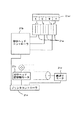
図2は、同コンピュータシステム10をブロック図により示している。
本コンピュータシステム10は、画像入力デバイスとして、スキャナ11aとデジタルスチルカメラ11bとビデオカメラ11cとを備えており、コンピュータ本体12に接続されている。それぞれの入力デバイスは画像をドットマトリクス状の画素で表現した画像データを生成してコンピュータ本体12に出力可能となっており、ここで同画像データはRGBの三原色においてそれぞれ256階調表示することにより、約1670万色を表現可能となっている。
【0039】
コンピュータ本体12には、外部補助記憶装置としてのフロッピー(R)ディスクドライブ13aとハードディスク13bとCD−ROMドライブ13cとが接続されており、ハードディスク13bにはシステム関連の主要プログラムが記録されており、フロッピー(R)ディスク13a1やCD−ROM13c1などから適宜必要なプログラムなどを読み込み可能となっている。
また、コンピュータ本体12を外部のネットワークなどに接続するための通信デバイスとしてモデム14aが接続されており、外部のネットワークに同公衆通信回線を介して接続し、ソフトウェアやデータをダウンロードして導入可能となっている。この例ではモデム14aにて電話回線を介して外部にアクセスするようにしているが、LANアダプタを介してネットワークに対してアクセスする構成とすることも可能である。この他、コンピュータ本体12の操作用にキーボード15aやマウス15bも接続されている。
【0040】
さらに、画像出力デバイスとして、ディスプレイ17aとカラープリンタ17bとを備えている。ディスプレイ17aについては水平方向に800画素と垂直方向に600画素の表示エリアを備えており、各画素毎に上述した1670万色の表示が可能となっている。むろん、この解像度は一例に過ぎず、640×480画素であったり、1024×768画素であるなど、適宜、変更可能である。
【0041】
また、カラープリンタ17bはインクジェットプリンタであり、CMYKの四色の色インクを用いて記録媒体たる印刷用紙上にドットを付して画像を印刷可能となっている。画像密度は360×360DPIや720×720DPIといった高密度印刷が可能となっているが、階調表限については色インクを付すか否かといった2階調表現となっている。
一方、このような画像入力デバイスを使用して画像を入力しつつ、画像出力デバイスに表示あるいは出力するため、コンピュータ本体12内では所定のプログラムが実行されることになる。そのうち、基本プログラムとして稼働しているのはオペレーティングシステム(OS)12aであり、このオペレーティングシステム12aにはディスプレイ17aでの表示を行わせるディスプレイドライバ(DSP DRV)12bとカラープリンタ17bに印刷出力を行わせるプリンタドライバ(PRT DRV)12cが組み込まれている。これらのドライバ12b,12cの類はディスプレイ17aやカラープリンタ17bの機種に依存しており、それぞれの機種に応じてオペレーティングシステム12aに対して追加変更可能である。また、機種に依存して標準処理以上の付加機能を実現することもできるようになっている。すなわち、オペレーティングシステム12aという標準システム上で共通化した処理体系を維持しつつ、許容される範囲内での各種の追加的処理を実現できる。
【0042】
むろん、このようなプログラムを実行する前提として、コンピュータ本体12内にはCPU12eとRAM12fとROM12gとI/O12hなどが備えられており、演算処理を実行するCPU12eがRAM12fを一時的なワークエリアや設定記憶領域として使用したりプログラム領域として使用しながら、ROM12gに書き込まれた基本プログラムを適宜実行し、I/O12hを介して接続されている外部機器及び内部機器などを制御している。
【0043】
ここで、基本プログラムとしてのオペレーティングシステム12a上でアプリケーション12dが実行される。アプリケーション12dの処理内容は様々であり、操作デバイスとしてのキーボード15aやマウス15bの操作を監視し、操作された場合には各種の外部機器を適切に制御して対応する演算処理などを実行し、さらには、処理結果をディスプレイ17aに表示したり、カラープリンタ17bに出力したりすることになる。
【0044】
かかるコンピュータシステム10では、画像入力デバイスであるスキャナ11aなどで画像データを取得し、アプリケーション12dによる所定の画像処理を実行した後、画像出力デバイスとしてのディスプレイ17aやカラープリンタ17bに表示出力することが可能である。この場合、単に画素同士の対応に着目すると、カラープリンタ17bにおける画素密度とスキャナ11aの画素密度が一致する場合にはスキャンした元画像の大きさと印刷される画像の大きさとが一致するが、両者にずれがあれば画像の大きさが異なることになる。スキャナ11aの場合はカラープリンタ17bの画素密度と近似するものも多いが、高画質化のために画素密度の向上が図られているカラープリンタ17bの画素密度の方が一般的な画像入力デバイスにおける画素密度よりも高密度であることが多い。特に、ディスプレイ17aの表示密度と比較すると各段に高密度であり、ディスプレイ17a上での表示を画素単位で一致させて印刷させるとなると極めて小さな画像になりかねない。
【0045】
このため、オペレーティングシステム12aで基準となる画素密度を決定しつつ実際のデバイスごとの画素密度の相違を解消するために解像度変換が実施される。例えば、ディスプレイ17aの解像度が72DPIであるとするときに、オペレーティングシステム12aで360DPIを基準とするならば、ディスプレイドライバ12bが両者の間の解像度変換を実施する。また、同様の状況でカラープリンタ17bの解像度が720DPIであればプリンタドライバ12cが解像度変換を実施する。
【0046】
解像度変換は画像データにおける構成画素数を増やす処理にあたるので補間処理に該当し、これらのディスプレイドライバ12bやプリンタドライバ12cがその機能の一つとして補間処理を実施する。ここにおいて、ディスプレイドライバ12bやプリンタドライバ12cは上述した第一の補間処理手段C12,第二の補間処理手段C13を実行可能であり、さらに第一重畳比率決定手段C14,画像データ重畳手段C15,画像データ出力手段C16を実行し、画像の性質に応じた比率の重畳を行うようにしている。
【0047】
なお、かかるディスプレイドライバ12bやプリンタドライバ12cは、ハードディスク13bに記憶されており、起動時にコンピュータ本体12にて読み込まれて稼働する。また、導入時にはCD−ROM13c1であるとかフロッピー(R)ディスク13a1などの媒体に記録されてインストールされる。従って、これらの媒体は画像データ補間プログラムを記録した媒体を構成する。
本実施形態においては、画像データ補間装置をコンピュータシステム10として実現しているが、必ずしもかかるコンピュータシステムを必要とするわけではなく、同様の画像データに対して補間処理が必要なシステムであればよい。例えば、図3に示すようにデジタルスチルカメラ11b1内に補間処理する画像データ補間装置を組み込み、補間処理した画像データを用いてディスプレイ17a1に表示させたりカラープリンタ17b1に印字させるようなシステムであっても良い。また、図4に示すように、コンピュータシステムを介することなく画像データを入力して印刷するカラープリンタ17b2においては、スキャナ11a2やデジタルスチルカメラ11b2あるいはモデム14a2等を介して入力される画像データについて自動的に解像度変換を行って印刷処理するように構成することも可能である。
この他、図5に示すようなカラーファクシミリ装置18aや図6に示すようなカラーコピー装置18bといった画像データを扱う各種の装置においても当然に適用可能である。
【0048】
図7は上述したプリンタドライバ12cが実行する解像度変換に関連するソフトウェアフローを示している。図7においてステップS102では元画像データを取得する。アプリケーション12dにてスキャナ11aから画像を読み込み、所定の画像処理を行った後で印刷処理すると、所定の解像度の印刷データはオペレーティングシステム12aを介してプリンタドライバ12cが取得するので、この段階が該当する。この処理はソフトウェアとしてみるときに画像データ取得工程あるいは画像データ取得機能ということになるが、当該画像データ取得ステップを含めてコンピュータに実行させる各種のステップは、オペレーティングシステム12a自体やハードウェアを直接に含まないものとして理解することができる。これに対して、CPUなどのハードウェアと有機一体的に結合したものと考えると画像データ取得手段C11に該当する。
【0049】
ステップS104では読み込んだ画像データにおいて、補間される画素を注目画素とし、当該注目画素を中心として周辺の5×5画素の領域の画素データを参照画素としつつ、同参照画素の輝度値のヒストグラムを作成する。ステップS106では得られたヒストグラムにて異なる輝度値が出現する回数を取得し、同出現回数が15より小さいか否かを判別する。異なる輝度値が多いものほど参照画素中に色数が多いことから、ここでは輝度値出現回数が15より小さいものを非自然画であるとしており、上記ステップS106にて出現回数が15より小さいと判別されたときにステップS110にて上記第一の補間処理の重畳比率(rate)を1にする。
【0050】
ステップS106にて輝度値出現回数が15より小さくないと判別されたときにはステップS108で評価関数Fによってrateを決定する。詳細は後述するが、この評価関数Fは上記参照画素の輝度値幅すなわち参照画素中の最大輝度値Ymaxと最小輝度値Yminとの差の関数である。従って、ステップS104,S106,S108,S110に示す一連の処理が第一重畳比率決定工程あるいは第一重畳比率決定機能に相当するし、これらがCPUなどのハードウェアと有機一体的に結合したものと考えると第一重畳比率決定手段C14を構成することになる。
【0051】
ステップS108あるいはステップS110にてrateを決定すると、ステップS112にて同rateが「0」であるか否かを判別し、rateが「0」である時には第一の補間処理を行わないようになっている。ステップS112にてrateが「0」であると判別されないときにはステップS114にて第一の補間処理を実行する。従って、この処理が上記第一の補間処理工程あるいは第一の補間処理機能に相当するし、これらがCPUなどのハードウェアと有機一体的に結合したものと考えると第一の補間処理手段C12を構成することになる。
【0052】
さらに、ステップS116ではrateが「1」であるか否かを判別し、rateが「1」である時には第二の補間処理を行わないようになっている。ステップS116にてrateが「1」であると判別されないときにはステップS118にて第二の補間処理を実行する。従って、この処理が上記第二の補間処理工程あるいは第二の補間処理機能に相当するし、これらがCPUなどのハードウェアと有機一体的に結合したものと考えると第二の補間処理手段C13を構成することになる。このようにしてrateを決定し、第一の補間処理あるいは第二の補間処理を実行した後にはステップS120にて当該rateに基づいて以下の式により画素データを重畳して補間画素を生成する。
重畳データ=
(第一の補間処理)×rate+(第二の補間処理)×(1−rate)
…(1)
従って、この処理が上記画像データ重畳工程あるいは画像データ重畳機能に相当し、これらがCPUなどのハードウェアと有機一体的に結合したものと考えると画像データ重畳手段C15を構成することになる。このようにして上記注目画素に対する補間データの生成が終了すると、ステップS122にて上記入力した元画像データの全注目画素についての重畳処理が終了したか否かを判別し、全注目画素についての処理が終了するまで上記ステップS104以降の処理を繰り返す。全注目画素についての重畳処理が終了したら、ステップS124にて補間された画像データを出力する。プリンタドライバ12cの場合、解像度変換だけで印刷データが得られるわけではなく、色変換であるとか、ハーフトーン処理が必要になる。従って、ここで画像データを出力するとは、次の段階へのデータの受け渡しを意味し、この処理が上記画像データ出力工程あるいは画像データ出力機能に相当し、これらがCPUなどのハードウェアと有機一体的に結合したものと考えると画像データ出力手段C16を構成することになる。
【0053】
次に、以上のフローのステップS114における第一の補間処理フローを説明する。図8はかかる第一の補間処理フローを示しており、同図において、ステップS202では、パターンマッチングを行うため、上記ステップS104で取得した5×5画素の領域の画素データからさらに、上記注目画素を中心とした周辺3×3画素の領域の画素データを抽出する。そして、ステップS204では、上記抽出画素の輝度値が後述する所定のしきい値より大きいか否かによって当該画素データを2値パターン化する。
【0054】
ステップS206では上記ステップS204で2値パターンが予め用意された所定のエッジパターンと一致するか否かを判別する。ここで、エッジパターンは上記3×3画素の領域が「30°」,「45°」等のエッジを有している場合の2値パターンであり、当該エッジパターンと上記ステップS204で作成した2値パターンとが一致するか否かを判別することにより当該3×3画素の領域がエッジであるか否かを判別している。
【0055】
ステップS206にて両パターンが一致すると判別されたときには、ステップS208において上記エッジパターンに応じて予め決定された規則によって補間画素を生成する。フローでは、このパターン一致時の処補間処理をパターンマッチング法と表記している。ステップS206にて両パターンが一致すると判別されないときには、ステップS210においてニアリスト法で補間画素を生成する。このようにして、上記注目画素に対する補間処理を実行したら、ステップS212にて当該データをRAM12fに格納して上記図7に示すフローに復帰する。
【0056】
次に、以上のようなフローに対するより具体的な処理について説明する。本実施形態においては、ステップS102で取得する元画像がコンピュータグラフィックス(非自然画)であるか写真(自然画)であるかを判定し、判定結果を重畳比率に反映させるようになっている。むろん、補間対象画像の性質判別に基づく補間手法決定の誤りを防止するために、上記rateを「1」もしくは「0」に固定しない構成も可能であるが、本実施形態においては輝度値出現回数が15より小さければまず非自然画であるとし、非自然画に対して第二の補間処理を実行して画像の輪郭を曖昧にさせないようにすることを重視してある。
【0057】
この判別は具体的には図9に示す輝度値のヒストグラムを利用しており、ステップ104においては、5×5画素の領域の各参照画素について輝度値を求め、輝度が取りうる範囲において画素数のヒストグラムを集計する。そして当該輝度値出現回数、すなわち分布数が「0」でない輝度値がいくつ表れているかカウントし、ステップS106における判別を行う。むろん、一画像において1670万色のうちで同じ輝度となる色が複数存在するのは当然であり、非自然画との比較だけに着目すれば、色であっても輝度であっても多いか少ないかの比較は可能であり、輝度値の他、色の出現回数を集計して非自然画か否かの判別を行っても良い。
【0058】
尚、上記参照画素についての画素データがその成分要素として輝度を持っていればその輝度値を用いて分布を求めることが可能である。しかしながら、輝度値が直接の成分値となっていない画像データの場合でも、間接的には輝度を表す成分値を備えている。従って、輝度値が直接の成分値となっていない表色空間から輝度値が直接の成分値となっている表色空間への変換を行えば輝度値を得ることができる。
【0059】
異なる表色空間の間での色変換は変換式によって一義的に定まるものではなく、それぞれの成分値を座標とする色空間について相互に対応関係を求めておき、この対応関係を記憶した色変換テーブルを参照して逐次変換する必要がある。すると、厳密には1670万個の要素の色変換テーブルを持たなければならない。効率的な記憶資源の利用を考えた結果、すべての座標値についての対応関係を用意しておくのではなく、通常は適当なとびとびの格子点について対応関係を用意しておき、補間演算を併用するようにしている。しかし、かかる補間演算はいくつかの乗算や加算を経て可能となるものであるため、演算処理量は膨大となってくる。
【0060】
すなわち、フルサイズの色変換テーブルを使用するのであれば処理量としては少なくなるもののテーブルサイズが非現実的な問題となり、テーブルサイズを現実的なサイズにすれば演算処理量が非現実的となることが多い。このような状況に鑑み、本実施形態においては簡略化した輝度値計算法を採用している。すなわち、本実施形態の補間対象画像データはRGBの表色空間を採用しており、各成分値は色の明るさを示しているので、それぞれの成分値を単独で見た場合に輝度に線形に対応しているという性質がある。従って、各色の加算割合を考慮することなく単に
Y=(R+G+B)/3
としても各画素の輝度値を反映したデータであると言え、本実施形態では当該式によって値度値を算出している。
【0061】
むろん、輝度値の計算はこのような手法に限ることはなく、テレビジョンなどの場合に利用されているように、RGBの三原色から輝度を求める次式の変換式を採用しても良い。
Y=0.30R+0.59G+0.11B
このようにすれば、三回の乗算と二回の加算だけで輝度値を求めることができるようになる。
このような、輝度値のヒストグラムにおいて分布数が「0」でない輝度値が15より多ければ、ステップS108にて予め決定された評価関数Fによって重畳比率rateを決定する。図10の実線はかかる評価関数F(y)の具体例を示しており、同評価関数は「y」が「0≦y≦255」の範囲で値を有し、「0≦F(y)≦1」の範囲で変動する。また、「0≦y≦64」の範囲では「F(y)=0」であり、「192≦y≦255」の範囲では「F(y)=1」であり、「64≦y≦192」の範囲ではF(y)は「0」から「1」まで直線的に増加する。ここで、「y」には上記図9における輝度値幅「Ymax−Ymin」が代入される。従って、輝度値幅が大きいほど、すなわち参照画素相互の関係がよりエッジらしいものほどrateが大きくなる。
【0062】
また、このようにエッジらしいものほどrateを大きくするための関数は上記図10に示す例に限る必要はなく、輝度値幅を変数としたときに輝度値幅とともに単調に増加する関数であればよい。また、必ずしも評価関数の最大値を「1」にし、最小値を「0」にする必要もなく、図10の点線に示すように評価関数の最大値を「0.7」にして第一の補間処理のみを実行することを防止したり、輝度値幅「0」〜「255」にわたってなめらかに変化する評価関数を採用することもできる。
【0063】
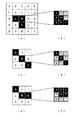
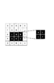
図9のようなヒストグラムであれば、分布数が「0」でない輝度値が19個あるのでステップS106の判別を経てステップS108にて図10に示す評価関数によってrateが決定され、ステップS114とステップS118にてそれぞれ第一の補間処理と第二の補間処理が実行される。図11(a)は上記図8のステップS202において抽出する3×3画素の輝度パターンの一例を示している。ステップS204では同図(a)に示す輝度パターンから同図(b)に示す2値パターンを作成するようになっており、まず各画素Pijについて上記輝度値計算式に基づいて輝度値Yijを計算する。
【0064】
そして、これらの輝度値の最大値Ymaxと最小値Yminとの中間の値を求め、当該中間の値を上記しきい値Ytとする。しきい値が算出された後には各輝度値Yijとしきい値Ytとを比較し、同しきい値より輝度値が大きいものと小さいものとに分けて2値の画素パターンに変換する。むろん、しきい値の選び方や2値パターン作成の手法は上記の態様に限る必要はなく、輝度値の中間値128をしきい値にしたり、輝度値の最小値が「45」以下の場合はこのような極端な輝度値は使用しないことにして最小値を「45」として取り扱うなど種々の態様を採用可能である。
【0065】
図11(b)に示す2値パターンが作成されると、ステップS206にて同2値パターンが予め用意されたエッジパターンと一致するか否かが判別される。ここで予め用意するエッジパターンは種々のパターンが採用可能である。具体的には、図11(b)に示すパターンは予め用意されているエッジパターンと一致する。ここで、同図(b)のエッジパターンと一致するということは、同図のj方向における上方側に位置する画素の輝度値と同j方向における下方側に位置する画素の輝度値とでは輝度値差が大きい傾向にあり、かつ紙面左右方向には輝度値差があまりないことを示している。従って、このようなパターンは紙面左右方向に平行なエッジであることになる。そこで、このエッジパターンに対して予め決められた規則で画素補間処理を行う。
【0066】
この予め決められた規則にはエッジパターンによって種々の規則があるが、概略的には上記3×3画素の領域内の所定画素の階調値に対して当該画素と補間される画素との距離の逆比を重みとした加重平均を計算するものである。ここで、補間画素の生成時に加重平均を行う画素をどのような指針の基に選ぶかという点や、エッジの角度,方向等をどのように反映させるかという点において種々のバリエーションが考えられ、上記エッジパターンごとに所定のバリエーションを対応させるという意味でエッジパターンに対して予め決められた規則で画素補間処理を行うことになる。
【0067】
また、上記エッジパターンは3×3画素の領域であるが、上記エッジの角度や方向等を見極めるのには上記5×5画素の参照画素をも使用する。すなわち、エッジパターンは予め種々の2値パターンをデータベースとして持っている必要があるが、5×5画素の領域で予め所定のパターンを用意するとその数が膨大になってしまう。そこで、本実施形態においては、予め用意するエッジパターンの数が現実的な数となる3×3画素の領域に対して2値パターンを生成し、当該生成パターンとエッジパターンとが一致するか否かを判別した上でさらにエッジの性質を反映させるべく5×5画素の領域を参照する。
【0068】
以下、図11(b)に示す2値パターンとマッチすると判別された場合の画素補間処理規則を説明する。図12(a)は上記参照画素データたる5×5画素の領域を示しており、画素のそれぞれにA〜Yのアルファベットを付して個々の画素を区別している。かかる表記において上記パターンマッチングに使用する上記3×3画素の領域は「G,H,I,L,M,N,Q,R,S」の画素であり、上記注目画素は画素Mである。また、図12(a)は当該3×3画素の領域においてすでに2値パターン化した後の状態を示している。
【0069】
図12(b)は補間処理後の画素を示しており、注目画素Mは補間されて画素a〜iになる。かかる画素生成時の計算の基本式は次式に示すものであり、補間画素から元画素への距離の逆比を重みとした加重平均を実行している。ここで、生成される補間画素の階調値をxbar とし、Pnは参照される元画素(G,H,I,L,M,N,Q,R,S)の階調値であり、rnは生成される補間画素から参照されるそれぞれの元画素への距離である。
【0070】
【数1】

【0071】
本例に示す3×3画素のパターンは上述のように水平方向(i方向)には輝度値差があまりない、すなわち水平方向のエッジであるので、本式Pnには水平に並んでいる3画素のもののみが代入されるようになっており、原則として元画素L,M,Nの階調値が代入される。また、本実施形態においては、さらに上記水平方向のエッジと垂直な方向の輝度値変化をも反映させた補間を行うようになっており、当該水平方向のエッジと垂直な方向に輝度値が変化している場合にはPnに元画素Q,R,Sの階調値を代入し、エッジ変化の様子を補間画素g,h,iの階調値に反映させる。すなわち、注目画素Mの方がエッジ側の画素Rよりも値が大きい(小さい)ならば、画素Rでうめても強調にはならないため、注目画素をそのまま使用することとする。
【0072】
このため、補間計算を行う前に画素Mと画素Rとの輝度値を比較し、画素Rの輝度値が画素Mの輝度値より大きい場合には上記元画素Q,R,Sの階調値を上式に代入して補間画素g,h,iを生成している。この結果、補間画素d,e,fに比べて補間画素g,h,iの輝度値がより大きくなって補間された画像データにおいてエッジがより強調される。
この場合の具体的な判断条件は、
((M=エッジ)&(R>M))or((M≠エッジ)&(R<M))
であり、その際の計算式を示すと、
a=d=(Lx2+Mx2+N)/5
b=e=(L+Mx2+N)/4
c=f=(L+Mx2+Nx2)/5
g=(Qx4+Rx6+Sx3)/13
h=(Q+Rx2+S)/4
i=(Qx3+Rx6+Sx4)/13
となる。一方、画素Rの輝度値が画素Mの輝度値より小さい場合は強調処理は行わず元画素L,M,Nの階調値のみが使用される。
【0073】
この場合の具体的な判断条件は、
not(((M=エッジ)&(R>M))or((M≠エッジ)&(R<M)))であり、その際の計算式を示すと、
a=d=g=(Lx2+Mx2+N)/5
b=e=h=(L+Mx2+N)/4
c=f=i=(L+Mx2+Nx2)/5
となる。尚、上式で補間画素の階調値を計算するにあたり、元画素MをPnに代入する場合には重みとして距離の逆比を使用するとその値が大きくなりすぎるため、その場合のみ重みを半分にするようにしてある。
【0074】
本実施形態においては、以上の規則によって水平エッジに対してその垂直方向への輝度値変化を考慮しつつ補間処理を実行しているが、当該水平エッジ以外にも種々のエッジパターンについての処理が可能であり図13はその例を示している。上記ステップS206において同図(a)に示すパターンが発見されたときには、さらに3×3画素の領域外の所定画素を参照して同図(b)に示す補間画素を生成する。同パターンにおける規則では、補間画素a,d,e,g,h,iの階調値計算においては、元画素L,M,Rを使用する。
【0075】
補間画素b,c,fの階調値計算は5×5画素の領域に含まれる所定画素の輝度値に基づいて、いずれの画素を元画素にするかを変えている。すなわち、当該パターンが直角エッジであれば元画素L,M,Rを使用して補間画素b,c,fを生成するし、直角エッジでなければ元画素G,H,N,Sを使用して補間画素b,c,fを生成『する。
まず、本パターンが直角であるとする判断条件は、
(((M=K=エッジ)&(F=エッジでない))or((M=W=エッジ)&(X=エッジでない)))
or
(((M=K=エッジでない)&(F=エッジ))or((M=W=エッジでない)&(X=エッジ)))
であり、その際の計算式を示すと
c=(L+Mx2+R)/4
b=(Lx4+Mx6+Rx3)/13
f=(Lx3+Mx6+Rx4)/13
a=(Lx2+Mx2+R)/5
d=(Lx3+Mx3+Rx2)/8
e=(L+Mx2+R)/4
g=(L+M+R)/3
h=(Lx2+Mx3+Rx3)/8
i=(L+Mx2+Rx2)/5
となる。次に、この直角以外でも直角に近い第一のパターンとしての条件判断は、
(((M=F=エッジ)&(A=エッジでない))or((M=X=エッジ)&(Y=エッジでない)))
or
(((M=F=エッジでない)&(A=エッジ))or((M=X=エッジでない)&(Y=エッジ)))
であり、その際の計算式を示すと
c=(G+Hx2+Nx2+S)/6
b=(Lx4+Mx6+Rx3)/13
f=(Lx3+Mx6+Rx4)/13
となり、a,d,e,g,h,iについては同様の計算式とする。そして、上記二つの条件判断がいずれも成立しない場合の計算式を示すと、
c=(G+Hx2+Nx2+S)/6
b=(Gx15+Hx30+Nx20+Sx12)/77
f=(Gx12+Hx20+Nx30+Sx15)/77
となり、この場合もa,d,e,g,h,iについては同様の計算式とする。
【0076】
さらに、図13(c)に示すパターンが発見されたときには、同図(d)に示す補間画素を生成する。すなわち、同図(c)に示すパターンは3×3画素領域の対角線を結んだ直線の一部(45度のエッジ)らしいので、これらの直線を構成する元画素G、M、Sを使用して補間画素a,e,iを生成する。また、5×5画素の領域に含まれる所定画素の輝度値に基づいて元画素のエッジ角度や線の太さを判別し、当該判別に応じて補間画素b,c,f,d,g,hの生成に使用する元画素を「G,M,S」と「H,N」とで変更したり、「G,M,S」と「L,R」とで変更したりする。
【0077】
検出した45度のエッジか、45度エッジの一部なのか30度エッジの一部なのかの判断によって処理は3つに分岐する。この判断条件を図36に示す。なお、図中で破線で囲った説明は各判断の意図する内容である。
処理1が選択された際の計算式は、
b=(Gx5+Mx10+Sx4)/19
c=(G+Mx2+S)/4
f=(Gx4+Mx10+Sx5)/19
となり、処理2が選択された際の計算式は、
b=(Gx5+Mx10+Sx4)/19
c=(H+N)/2
f=(Gx4+Mx10+Sx5)/19
となり、処理3が選択された際の計算式は、
b=(Hx3+Nx2)/5
c=(H+N)/2
f=(Hx2+Nx3)/5
となる。これら以外の画素についての計算式は、
a=(Gx3+Mx6+Sx2)/11
d=(Gx5+Mx10+Sx4)/19
e=(G+Mx2+S)/4
g=(G+Mx2+R)/4
h=(Gx4+Mx10+Sx5)/19
i=(Gx2+Mx6+Sx3)/11
となる。
【0078】
図13(e)に示すパターンが発見されたときには、同図(f)に示す補間画素を生成する。すなわち、上記図(c)に示す直線よりさらに角度の浅い直線(30度のエッジ)らしいので、これらの直線を構成する元画素G,M,Nを使用して補間画素a,b,c,e,fを生成する。さらに、5×5画素の領域に含まれる所定画素の輝度値に基づいて元画素のエッジ角度や突出画素等を判別し、当該判別に応じて補間画素d,g,h,iの生成に使用する元画素を「G,M,N」と「L,R,S」とで変更する。
【0079】
より具体的に説明すると、検出した30度のエッジについて処理は4つに分岐する。この判断条件を図37に示す。なお、図中で破線で囲った説明は各判断の意図する内容である。
処理1が選択された際の計算式は、
d=(G+Mx2+N)/4
g=(G+Mx2+S)/4
h=(Gx3+Mx8+Nx5)/16
i=(G+Mx3+Nx3)/7
となり、処理2が選択された際の計算式は、
d=(G+Mx2+N)/4
g=(Lx2+Rx2+S)/5
h=(Lx4+Rx6+Sx3)/13
i=(Lx3+Rx6+Sx4)/13
となり、処理3が選択された際の計算式は、
d=(G+Mx2+N)/4
g=(Lx2+Rx2+S)/5
h=(Lx4+Rx6+Sx3)/13
i=(G+Mx3+Nx3)/7
となり、処理4が選択された際の計算式は、
d=(Lx15+Rx10+Sx6)/31
g=(Lx2+Rx2+S)/5
h=(Lx4+Rx6+Sx3)/13
i=(Lx3+Rx6+Sx4)/13
となる。これら以外の画素についての計算式は、
a=(Gx4+Mx6+Nx3)/13
b=(Gx3+Mx6+Nx4)/13
c=(G+Mx2+Nx2)/5
e=(Gx4+Mx6+Nx3)/13
f=(Gx2+Mx5+Nx5)/12
となる。
【0080】
以上示したエッジパターンや5×5画素領域の参照手法,使用する元画素の選択手法等はその例示であり、種々の態様が採用可能であるし、補間画素を生成する際の倍率も上述のように縦横にそれぞれ3倍の画素を生成する態様の他、2倍,4倍等種々の倍率を採用することもできる。
まず、2倍補間の例について説明する。図38〜図42は元画素Mから補間画素a〜補間画素dが生成される場合の対応を示しており、図38はパターンマッチングで水平エッジが発見された場合を示している。この場合も、注目画素Mの方がエッジ側の画素Rよりも値が大きい(小さい)ならば、画素Rでうめても強調にはならないため、注目画素をそのまま使用することとする。より具体的な判断条件は、
((M=エッジ)&(R>M))or((M=エッジでない)&(R<M))
であり、これが成立すれば強調処理を行う。その場合の計算式は、
a=b=M
c=d=R
となり、これ以外の場合は強調処理を行わないので、
a=b=c=d=M
となる。
【0081】
次に図39は、パターンマッチングで角エッジが発見された場合であり、直角のエッジか否かの判断条件は、
(((M=K=エッジ)&(F=エッジでない))or((M=W=エッジ)&(X=エッジでない)))
or(((M=K=エッジでない)&(F=エッジ))or((M=W=エッジでない)&(X=エッジ)))
であり、これが成立すれば直角であることを強調するために、
b=(L+R)/2
という式で計算し、そうでない場合には、
b=(Gx2+Hx3+Nx3+Sx2)/10
という式で計算する。その他の画素の計算式は、
a=(Lx3+Rx2)/5
c=(L+R)/2
d=(Lx2+Rx3)/5
となる。
【0082】
図40は、パターンマッチングで45度のエッジが発見された場合であり、45度のエッジの一部なのか30度のエッジの一部なのかの判断を行うため、図41に示す条件判断で2つの処理に分岐する。ここで、処理1となった場合の計算式は、
b=(G+S)/2
となり、処理2となった場合の計算式は、
b=(H+N)/2
となる。これ以外の画素の計算式は、
a=(Gx2+S)/3
c=(G+S)/2
d=(G+Sx2)/3
となる。
【0083】
図42は、パターンマッチングで30度のエッジが発見された場合であり、図43に示す条件判断で3つの処理に分岐する。ここで、処理1となった場合の計算式は、
c=(G+N)/2
d=(G+Nx2)/3
となり、処理2となった場合の計算式は、
c=(Lx3+Rx3+Sx2)/8
d=(Lx2+Rx3+Sx3)/8
となり、処理3となった場合の計算式は、
c=(Lx3+Rx3+Sx2)/8
d=(G+Nx2)/3
となる。これ以外の画素の計算式は、
a=(Gx3+Nx2)/5
b=(Gx2+Nx3)/5
となる。
【0084】
上記3×3画素の領域において予め用意したエッジパターンと上記2値パターンとが一致したと判別されないときには、第一の補間処理としてこのようなパターンマッチング法が使用せず、ニアリスト法が実行される。ニアリスト法は図14に示すように、周囲の四つの格子点Pij,Pi+1j,Pij+1,Pi+1j+1と内挿したい点Puvとの距離を求め、もっとも近い格子点のデータをそのまま移行させる。これを一般式で表すと、
Puv=Pij
ここで、i=[u+0.5]、j=[v+0.5]である。なお、[]はガウス記号で整数部分を取ることを示している。
【0085】
図15は、ニアリスト法で画素数を縦横3倍ずつに補間する状況を示している。補間する前には四隅の画素(□△○●)があるとして、補間して生成する画素にはこれらの画素のうちもっとも近い画素のデータをそのまま移行させている。すなわち、この例で言えば四隅の画素に隣接する画素についてそれぞれ複写することになる。また、かかる処理を行うと、図16に示すように白い画素を背景として黒い画素が斜めに配置される元画像は、図17に示すように黒の画素が縦横に3倍に拡大されつつ斜め方向に配置されることになる。ニアリスト法においては、画像のエッジがそのまま保持される特徴を有する。それ故に拡大すればジャギーが目立つもののエッジはエッジとして保持される。
【0086】
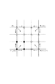
このようにして第一の補間処理による補間画素を生成した後、上記rateが「1」でなければさらに上記第二の補間処理を実行する。本実施形態においてはこの第二の補間処理としていわゆるキュービック法による補間処理を実行するようになっており、以下かかる処理を説明する。キュービック法は図18に示すように、内挿したい点Puvを取り囲む四つの格子点のみならず、その一周り外周の格子点を含む計16の格子点のデータを利用する。
【0087】
内挿点Puvを取り囲む計16の格子点がそれぞれに値を備えている場合に、内挿点Puvはそれらの影響を受けて決定される。例えば、一次式で補間しようとすれば、内挿点を挟む二つの格子点からの距離に反比例させて重みづけ加算すればよい。X軸方向に注目すると、内挿点Puvから上記16の格子点との距離は、図面上、左外側の格子点までの距離をx1、左内側の格子点までの距離をx2、右内側の格子点までの距離x3、右外側の格子点までの距離x4と表しつつ、このような距離に対応した影響度合いを関数f(x)で表すことにする。また、Y軸方向に注目すると、内挿点Puvから上記16の格子点との距離は、上方外側の格子点までの距離をy1、上方内側の格子点までの距離をy2、下方内側の格子点までの距離y3、下方外側の格子点までの距離y4と表しつつ、同様に影響度合いは関数f(y)で表せる。
【0088】
16の格子点は以上のような距離に応じた影響度合いで内挿点Puvに寄与するので、全ての格子点にデータに対してX軸方向とY軸方向のそれぞれの影響度合いを累積させる一般式は次式のようになる。
【0089】
【数2】
f(t) = {sin(πt)}/πt
となる。なお、上述した各距離x1〜x4,y1〜y4は格子点Puvの座標値(u,v)について絶対値を利用して次のように算出することになる。
x1 = 1+(u-|u|) y1 = 1+(v-|v|)
x2 = (u-|u|) y2 = (v-|v|)
x3 = 1-(u-|u|) y3 = 1-(v-|v|)
x4 = 2-(u-|u|) y4 = 2-(v-|v|)
以上の前提のもとでPについて展開すると、
【0090】
【数3】
【0091】
【数4】
【0092】
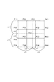
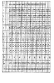
図19と図20はキュービック法にて補間される際の具体例を示している。理解を容易にするため、垂直方向についてのデータの変化はなく、水平方向についてエッジが生じているモデルについて説明する。また、補間する画素を3点とする。
まず、図20の具体的数値について説明する。補間前の画素の階調値を左列に「Original」として示しており、階調値「64」の画素(P0、P1、P2、P3)が4点並び、階調値「128」の画素(P4)を1点挟み、階調値「192」の画素(P5、P6、P7、P8、P9)が5点並んでいる。この場合、エッジは階調値「128」の画素の部分である。
【0093】
ここで各画素間に3点の画素(Pn1、Pn2、Pn3)を内挿することになると、内挿される画素間の距離は「0.25」となり、上述したx1〜x4は内挿点毎に表の中程の列の数値となる。x1〜x4に対応してf(x1)〜f(x4)も一義的に計算されることになり、例えば、x1,x2,x3,x4が、それぞれ「1.25」、「0.25」、「0.75」、「1.75」となる場合、それに対するf(t)については、概略「−0.14」、「0.89」、「0.30」、「−0.05」となる。また、x1,x2,x3,x4が、それぞれ「1.50」、「0.50」、「0.50」、「1.50」となる場合、それに対するf(t)については、「−0.125」、「0.625」、「0.625」、「−0.125」となる。また、x1,x2,x3,x4が、それぞれ「1.75」、「0.75」、「0.25」、「1.25」となる場合、それに対するf(t)については、概略「−0.05」、「0.30」、「0.89」、「−0.14」となる。以上の結果を用いて内挿点の階調値を演算した結果を表の右列に示しているとともに、図19においてグラフで示している。なお、このグラフの意味するところについて後に詳述する。
【0094】
垂直方向についてのデータの変化がないものとみなすと、演算は簡略化され、水平方向に並ぶ四つの格子点のデータ(P1,P2,P3,P4 )だけを参照しつつ、内挿点から各格子点までの距離に応じた影響度合いf(t)を利用して次のように算出できる。
P=P1・f(x1)+P21f(x2)+P3・f(x3)+P4・f(x4)
従って、内挿点P21について算出する場合には、
P21=64*f(1.25)+64*f(0.25)+64*f(0.75)+128*f(1.75)
=64*(-0.14063)+64*(0.890625)+64*(0.296875)+128*(-0.04688)
=61
となる。
【0095】
キュービック法によれば3次関数的に表せる以上、そのカーブの形状を調整することによって補間結果の品質を左右することができる。
その調整の一例として、
0<t<0.5 f(t) = -(8/7)t**3-(4/7)t**2+1
0.5<t<1 f(t) = (1-t)(10/7)
1<t<1.5 f(t) = (8/7)(t-1)**3+(4/7)(t-1)**2-(t-1)
1.5<t<2 f(t) = (3/7)(t-2)
としたものをハイブリッドバイキュービック法あるいはM(モディファイド)キュービック法と呼ぶことにする。
【0096】
図21はMキュービック法にて補間される際の具体例を示しており、キュービック法の場合と同じ仮定のモデルについて補間した結果を示している。また、図19にもMキュービック法による補間処理結果を示しており、この例では3次関数的なカーブがわずかに急峻となり、画像全体のイメージがシャープとなる。Mキュービック法,通常のキュービック法のいずれを使用するにしても、上記第二の補間処理においてはキュービック法によって補間画素を生成すれば、上記重畳データ計算式の変数、すなわち第一の補間処理データ,rate,第二の補間処理データの全てが算出されていることになるので、同式に値を代入することによって補間画素の重畳データを算出する。
【0097】
以下、図22(a)に示すような画像データに対して重畳処理が行われる様子を説明する。ここで、当該説明中における注目画素の周り5×5の領域では輝度値Yの出現回数が15より大きく、上記rateが「0」,「1」でないものとする。従って、ステップS108にてrateが計算された後、ステップS114にて第一の補間処理を実行する。ステップS202では図22(a)に示す注目画素周りの3×3画素の領域(実線領域)を抽出し、ステップS204で当該領域データから図22(b)に示す2値パターンを作成する。
【0098】
この2値パターンは予め用意された所定のエッジパターンと一致し、ステップS208にてパターンマッチング法による処理が行われ、図22(c)に示す補間画素が生成される。このとき、図22(a)に示す3×3の画素は対角線方向のエッジであって左下に向けて輝度勾配がついている。従って、図22(c)に示す補間画素においては、かかる3×3画素の性質を反映し対角線方向のエッジを保持しつつ左下に向けて輝度勾配がついてエッジを強調している。
【0099】
一方、ステップS118では図22(a)に示す画素データを使用して図22(d)に示す補間画素を生成する。ここで、上述のように、補間画素生成にはその周りの16個の画素データが使用され、例えば、図22(d)に黒点として示す右上の画素を生成するには図22(a)に示す実線および点線領域からなる16画素を使用する。かかる補間画素においては、キュービック法の性質から上記実線および点線領域の画素相互間の微妙な変化を反映しつつも上記パターンマッチング法に比べてエッジが曖昧になっている。すなわち、補間画素の対角線方向にエッジがあるが左下方向に向けての輝度勾配が緩やかになってエッジが曖昧になっている。
【0100】
このように第一の補間処理および第二の補間処理にて補間画素を生成した後には第一の補間処理による各補間画素にrateが乗じられ、第二の補間処理による各補間画素に(1−rate)が乗じられて図22(e)に示すように重畳画素が生成される。同図(e)に示すように、注目画素に対する重畳補間画素を生成すると、ステップS122の判別を経て新たな座標値の注目画素について全て補間処理し、ステップS124にて補間画像データを次段の処理へ引き渡す。ただし、補間倍率によっては補間画像データのデータ量が極めて多大になることもあるし、そもそもプリンタドライバ12cが利用可能なメモリ領域がさほど多くない場合もある。このような場合には一定のデータ量ごとに分けて出力するようにしても構わない。
【0101】
最後に、本実施形態の総括を図34に示している。スキャナ11aが写真をスキャンして電子化したものは元画像データとなり、以後の過程で処理対象となる。この元画像データを取得する手段は画像データ取得手段C11である。
ステップS104では、元画像データを読み込み、注目画素を中心とした周辺の5×5画素の領域で輝度値のヒストグラムを作成する。ステップS106では、得られたヒストグラムにて異なる輝度値が出現する回数を取得し、所定のしきい値よりも少なければ、画像の性質が単純な非自然画であると判断して第一の補間処理の重畳比率(rate)を1としてしまうが、多ければ画像の性質は自然画あるいは非自然画の混合画像である判断して評価関数Fによってrateを決定する。この評価関数Fは上記領域での最大輝度値Ymaxと最小輝度値Yminとの差の関数であり、エッジらしさを評価したものとなる。このようにして画像の性質から重畳比率を得る手段は第一重畳比率決定手段C14である。
【0102】
ステップS114では、注目画素を中心とした所定の領域でパターンマッチング法かニアリスト法によってエッジを保存しやすい傾向にある補間処理を行なうので、これが第一の補間処理手段C12となる。
一方、ステップS118では、画素相互間の微妙な変化を反映しつつもパターンマッチング法に比べてエッジが曖昧になるキュービック法で補間処理を行うので、これが第二の補間処理手段C13となる。
【0103】
そして、ステップS120では、上記のようにして決定された重畳比率(rate)を使用する計算式(1)により、それぞれ別個に補間処理された画素データに重み付けをつけて加算し、補間画素を生成する。この重畳比率の総和は当然「1」となる。むろん、この手段が画像データ重畳手段C15である。
以後、注目画素を逐次移動させていって全画素について処理を実施したら、補間画像が作成される。従って、ステップS124では完成した補間画像データを出力する。この過程が画像データ出力手段C16であるが、一例としてプリンタ17bに出力すれば印刷物が得られることになる。
【0104】
次に、本発明の他の実施形態を説明する。この実施形態では、画像データ補間プログラムを印刷システムに使用する。なお、上述した実施形態と共通する構成部品などについてはそのまま参照する。
上述したカラープリンタ17bには、プリンタドライバ12cを介してアプリケーション12dの処理結果が印刷データとして出力され、同カラープリンタ17bは色インクを用いて印刷用紙上にドットを付すことにより対応する画像を印刷する。
【0105】
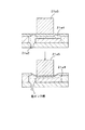
図23〜図25にはこのようなカラープリンタの一例としてカラーインクジェットプリンタ21の概略構成を示している。本カラーインクジェットプリンタ21は、三つの印字ヘッドユニットからなる印字ヘッド21aと、この印字ヘッド21aを制御する印字ヘッドコントローラ21bと、当該印字ヘッド21aを桁方向に移動させる印字ヘッド桁移動モータ21cと、印字用紙を行方向に送る紙送りモータ21dと、これらの印字ヘッドコントローラ21bと印字ヘッド桁移動モータ21cと紙送りモータ21dにおける外部機器とのインターフェイスにあたるプリンタコントローラ21eとからなるドット印刷機構を備え、印刷データに応じて印刷用紙である記録媒体上で印字ヘッド21aを走査しながら画像印刷可能となっている。
【0106】
また、図24は印字ヘッド21aの具体的な構成を示しており、図25はインク吐出時の動作を示している。印字ヘッド21aには色インクタンク21a1からノズル21a2へと至る微細な管路21a3が形成されており、同管路21a3の終端部分にはインク室21a4が形成されている。このインク室21a4の壁面は可撓性を有する素材で形成され、この壁面に電歪素子であるピエゾ素子21a5が備えられている。このピエゾ素子21a5は電圧を印加することによって結晶構造が歪み、高速な電気−機械エネルギー変換を行うものであるが、かかる結晶構造の歪み動作によって上記インク室21a4の壁面を押し、当該インク室21a4の容積を減少させる。すると、このインク室21a4に連通するノズル21a2からは所定量の色インク粒が勢いよく吐出することになる。このポンプ構造をマイクロポンプ機構と呼ぶことにする。
【0107】
なお、一つの印字ヘッドユニットには独立した二列のノズル21a2が形成されており、各列のノズル21a2には独立して色インクが供給されるようになっている。従って、三つの印字ヘッドユニットでそれぞれ二列のノズルを備えることになり、最大限に利用して六色の色インクを使用することも可能である。図23に示す例では、左列の印字ヘッドユニットにおける二列を黒インクに利用し、中程の印字ヘッドユニットにおける一列だけを使用してシアン色インクに利用し、右列の印字ヘッドユニットにおける左右の二列をそれぞれマゼンタ色インクとイエロー色インクに利用している。
【0108】
一方、印字ヘッド21aに形成されているノズル21a2の鉛直方向の間隔は印刷解像度とは一致せず、一般的にはこのノズル21a2は印刷解像度よりも大きな間隔で形成されている。これにもかかわらずより高解像度の印刷を可能とするのは、紙送り方向について紙送りモータ21dを制御するからである。例えば、ノズル21a2の間隔の間で紙を8段階で送り、各段階毎に印字ヘッド21aを桁送り方向に操作して印刷すれば解像度は向上する。むろん、桁送り方向については任意の間隔で色インクを吐出すればそれが解像度と言えるから、タイミングの制御次第と言える。なお、厳密な意味では色インクのドット径も解像度の要素となりえるが、ここでは理解の簡便のため無視することにする。
【0109】
本実施形態においては、上述したようなハードウェアシステムを前提とし、コンピュータシステム10の画像入力デバイスで取得した画像データに基づいて印刷を実行する。その際、元の画像データの解像度とカラープリンタ17bの解像度とに差がある場合には補間処理を実行することになる。ここで、アプリケーション12dが印刷処理を実行した際にカラープリンタ17bに対して印刷データが出力される際の解像度と階調度の変化について説明する。
【0110】
図26は画像データの流れを示している。アプリケーション12dはオペレーティングシステム12aに対して印刷要求を発生し、その際に出力サイズと印刷用紙と印刷速度とインクの種類とRGB256階調の画像データを受け渡す。すると、オペレーティングシステム12aはプリンタドライバ12cに対してこの出力サイズと印刷用紙と印刷速度とインクの種類と画像データを受け渡す。ここで、オペレーティングシステム12aはディスプレイドライバ12bを介してディスプレイ17aに表示を行いつつ、キーボード15aやマウス15bの操作結果をプリンタドライバ12cに出力し、プリンタドライバ12cは上記指定された出力サイズになるよう画像補間処理を実行して印刷データを生成する。通常、この印刷データはCMYK2階調であり、オペレーティングシステム12aを介してハードウェアポートよりカラープリンタ17bに出力されることになる。
【0111】
このように、本実施形態においては、印刷制御プログラムをコンピュータシスム10にて実行してカラープリンタ17bに印刷データを出力しているが、対象となる印刷装置は上述したインクジェット方式のカラープリンタ21に限定されるものではない。例えば、同カラープリンタ21はマイクロポンプ機構を採用するインクジェット方式のものであるがマイクロポンプ機構以外のものを採用することも可能である。図27に示すようにノズル21a6近傍の管路21a7の壁面にヒータ21a8を設けておくとともに、このヒータ21a8に加熱して気泡を発生させ、その圧力で色インクを吐出するようなバブルジェット(R)方式のポンプ機構も実用化されている。
【0112】
また、他の機構として図28にはいわゆる電子写真方式のカラープリンタ22の主要部概略構成を示している。感光体としての回転ドラム22aの周縁には回転方向に対応して帯電装置22bと露光装置22cと現像装置22dと転写装置22eとが配置され、帯電装置22bにて回転ドラム22aの周面を均一に帯電させた後、露光装置22cによって画像部分の帯電を除去し、現像装置22dで帯電していない部分にトナーを付着させ、転写装置22eによって同トナーを記録媒体としての紙上に転写させる。その後、ヒータ22fとローラ22gとの間を通過させて同トナーを溶融して紙に定着させている。そして、これらが一組となって一色のトナーによる印刷を行わせることになるので、合計四色分が個別に備えられている。
【0113】
すなわち、その印刷装置の具体的な構成は特に限定されるものではないし、このような個別的な印刷手法の適用範囲のみならずその適用態様についても各種の変更が可能である。
次に、上述した印刷システムを利用して出力解像度に応じた最適な画像処理を実行する処理について説明する。
図29は、この印刷システムの概略構成を示すブロック図である。印刷品質取得手段C21は、実行された印刷ジョブにおいて印刷させようとする印刷品質を取得し、第一の補間処理手段C22および第二の補間処理手段C23はこの画像データにおける構成画素数を増やす補間処理を行う。ここで、第一の補間処理手段C22は補間処理としてパターンマッチング法とニアリスト法とを実行可能になっており、第二の補間処理手段C23は補間処理としてキュービック法を実行可能になっている。
【0114】
第二重畳比率決定手段C24は上記印刷品質取得手段C21が取得した印刷品質に基づいて上記第一の補間処理手段C22および第二の補間処理手段C23による補間画素の重畳比率を決定する。同第二重畳比率決定手段C24が重畳比率を決定すると、画像データ重畳手段C25が当該重畳比率にて上記第一の補間処理手段C22および第二の補間処理手段C23による補間画素データを重畳する。そして、印刷制御処理手段C26は画像データ重畳手段C25が重畳した画素データに基づいて印刷用データを生成するとともに印刷を実行する。
【0115】
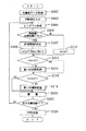
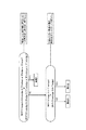
図30は上述したプリンタドライバ12cが実行する印刷処理に関連するソフトウェアフローを示している。図30においてステップS302では元画像データを取得する。例えば、アプリケーション12dにてスキャナ11aから画像を読み込み、所定の画像処理を行った後で印刷処理すると、所定の解像度の画像データがオペレーティングシステム12aを介してプリンタドライバ12cに引き渡されるため、この引渡の段階が該当する。
【0116】
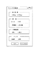
ステップS303では印刷設定を入力する。アプリケーション12dにて印刷処理を実行する際には、オペレーティングシステム12aがGUI環境を提供するものとすると図31に示すように印刷操作用のウィンドウ表示が行われる。ここで入力されるパラメータなどは各種のものを採用可能であるが、本実施形態においては、「(印刷の)部数」、「開始ページ」、「終了ページ」などがある。また、操作指示ボタンとしては「OK」ボタンと「キャンセル」ボタンとともに、「プリンタの設定」ボタンも用意されている。
【0117】
「プリンタの設定」を指示すると、図32に示すようなウィンドウ表示が行われる。このウィンドウ表示はプリンタ毎の機能に応じた各種の設定を行うために用意されており、後述するようにこのウィンドウにおける設定内容に応じて重畳比率が変更される。本例では「(印刷)解像度」として「360dpi」と「720dpi」の一方を選択できる。また、「用紙」として「A4」か「B5」のサイズおよび「普通紙」か「光沢紙」の品質、「印刷速度」として「速い」か「遅い」か、「インク」として「顔料」か「染料」かを選択できる。むろん、この印刷設定は一例であり、これらの全てをユーザに選択させるように構成する必要はなく、上記カラープリンタ17bと双方向通信を行ってインク種類等を行う等種々の態様を採用可能である。
【0118】
本実施形態においては、上述の設定内容はオペレーティングシステム12aの管理下にある設定ファイルに格納されるようになっており、既に設定がなされているのであれば当該設定ファイルを参照して読み出すし、操作者が印刷操作に伴って設定内容を変更する場合には変更後の設定内容を印刷設定として読み出す。このようなステップS303の処理はソフトウェアとしてみるときに上記印刷品質取得工程あるいは印刷品質取得機能ということになるが、当該印刷品質取得工程を含めてコンピュータに実行させる各種のステップは、オペレーティングシステム12a自体やハードウェアを直接に含まないものとして理解することができる。これに対して、CPUなどのハードウェアと有機一体的に結合したものと考えると印刷品質取得手段C21に該当する。
【0119】
ステップS304では読み込んだ画像データにおいて、補間される画素を注目画素とし、当該注目画素を中心として周辺の5×5画素の領域の画素データを参照画素としつつ、同参照画素の輝度値のヒストグラムを作成する。ステップS306では得られたヒストグラムにて異なる輝度値が出現する回数を取得し、同出現回数が15より小さいか否かを判別する。異なる輝度値が多いものほど参照画素中に色数が多いことから、ここでは輝度値出現回数が15より小さいものを非自然画であるとしており、上記ステップS306にて出現回数が15より小さいと判別されたときにステップS310にて上記第一の補間処理の重畳比率(rate)を1にする。
【0120】
ステップS306にて輝度値出現回数が15より小さくないと判別されたときにはステップS307にて上記ステップS303で入力した印刷設定内容に基づいて評価関数Fを決定する。同ステップS307における評価関数Fの決定では印刷品質が高いときに上記第二の補間処理の重畳比率を大きくなるように評価関数F決定する。詳細は後述するが、本実施形態においては印刷品質が高い場合と低い場合との2種の評価関数が用意されており、印刷品質が高い場合の評価関数値は印刷品質が低い場合の評価関数値より小さくなっている。また、この評価関数Fは上記参照画素の輝度値幅すなわち参照画素中の最大輝度値Ymaxと最小輝度値Yminとの差の関数である。
【0121】
ステップS308では上記ステップS307にて決定された評価関数Fに対して上記ヒストグラムに基づく最大輝度値Ymaxと最小輝度値Yminとの差を代入し、rateを決定する。従って、ステップS304,S306,S307,S308,S310に示す一連の処理が第二重畳比率決定工程あるいは第二重畳比率決定機能に相当するし、これらがCPUなどのハードウェアと有機一体的に結合したものと考えると第二重畳比率決定手段C24を構成することになる。
【0122】
ステップS308あるいはステップS310にてrateを決定すると、ステップS312にて同rateが「0」であるか否かを判別し、rateが「0」である時には第一の補間処理を行わないようになっている。ステップS312にてrateが「0」であると判別されないときにはステップS314にて第一の補間処理を実行する。従って、この処理が上記第一の補間処理工程あるいは第一の補間処理機能に相当するし、これらがCPUなどのハードウェアと有機一体的に結合したものと考えると第一の補間処理手段C22を構成することになる。
【0123】
さらに、ステップS316ではrateが「1」であるか否かを判別し、rateが「1」である時には第二の補間処理を行わないようになっている。ステップS316にてrateが「1」であると判別されないときにはステップS318にて第二の補間処理を実行する。従って、この処理が上記第二の補間処理工程あるいは第二の補間処理機能に相当するし、これらがCPUなどのハードウェアと有機一体的に結合したものと考えると第二の補間処理手段C23を構成することになる。このようにしてrateを決定し、第一の補間処理あるいは第二の補間処理を実行した後にはステップS320にて当該rateに基づいて上述した式(1)により画素データを重畳して補間画素を生成する。
重畳データ=
(第一の補間処理)×rate+(第二の補間処理)×(1−rate)
…(1)
従って、この処理が上記画像データ重畳工程あるいは画像データ重畳機能に相当し、これらがCPUなどのハードウェアと有機一体的に結合したものと考えると画像データ重畳手段C25を構成することになる。このようにして上記注目画素に対する補間データの生成が終了すると、ステップS322にて上記入力した元画像データの全注目画素についての重畳処理が終了したか否かを判別し、全注目画素についての処理が終了するまで上記ステップS304以降の処理を繰り返す。
【0124】
全注目画素についての重畳処理が終了したら、ステップS324にて補間された画像データに基づく印刷を行う。プリンタドライバ12cの場合、解像度変換だけで印刷データが得られるわけではなく、色変換であるとか、ハーフトーン処理が必要になる。従って、ここでは、かかる変換処理等を実行した上で印刷データを上記カラープリンタ17bに出力しており、この処理が上記印刷制御処理工程あるいは印刷制御処理機能に相当し、これらがCPUなどのハードウェアと有機一体的に結合したものと考えると印刷制御処理手段C26を構成することになる。
【0125】
次に、以上のようなフローに対するより具体的な処理について説明する。本実施形態においては、ステップS302で取得する元画像がコンピュータグラフィックス(非自然画)であるか写真(自然画)であるかを判定し、印刷品質のみならず当該判定結果を重畳比率に反映させるようになっている。むろん、補間手法決定の誤りを防止するために、上記rateを「1」もしくは「0」に固定しない構成も可能であるが、本実施形態においては輝度値出現回数が15より小さければまず非自然画であるとし、非自然画に対して第二の補間処理を実行して画像の輪郭を曖昧にさせないようにすることを重視してある。
【0126】
この判別は具体的には図14に示す輝度値のヒストグラムを利用しており、ステップ104においては、5×5画素の領域の各参照画素について輝度値を求め、輝度が取りうる範囲において画素数のヒストグラムを集計する。そして当該輝度値出現回数すなわち、分布数が「0」でない輝度値がいくつ表れているかカウントし、ステップS306における判別を行う。
このように、輝度値のヒストグラムにおいて分布数が「0」でない輝度値が15より多ければ、上記第一の補間処理の重畳比率を評価関数によって決定する。本実施形態においては、評価関数は予め高印刷品質用と低印刷品質用との2種類用意されており、上記図32に示すウィンドウで設定した設定内容のうち、一つでも高品質を示すものがあればステップS306にて高印刷品質用評価関数を使用するよう決定する。図33は評価関数F(y)の一例を示しており、同図F1が低印刷品質用評価関数であり、同図F2が高印刷品質用評価関数である。
【0127】
評価関数F1(y)は「y」が「0≦y≦255」の範囲で値を有し、「0≦F(y)≦1」の範囲で変動する。また、「0≦y≦64」の範囲では「F(y)=0」であり、「192≦y≦255」の範囲では「F(y)=1」であり、「64≦y≦192」の範囲ではF(y)は「0」から「1」まで直線的に増加する。また、評価関数F2(y)は「y」が「0≦y≦255」の範囲で値を有し、「0≦F(y)≦0.7」の範囲で変動する。また、「0≦y≦64」の範囲では「F(y)=0」であり、「192≦y≦255」の範囲では「F(y)=0.7」であり、「64≦y≦192」の範囲ではF(y)は「0」から「0.7」まで直線的に増加する。
【0128】
ここで、「y」には上記図14における輝度値幅「Ymax−Ymin」が代入される。従って、輝度値幅が大きいほど、すなわち参照画素相互の関係がよりエッジらしいものほどrateが大きくなる。さらに、同じ輝度値幅であっても評価関数F1の値は常に評価関数F2の値以上である。すなわち、同じ輝度値幅でも高品質印刷の場合は画像の階調性を損なわないで補間処理を行う第二の補間処理の重畳比率が大きくなる。
【0129】
「高印刷解像度」,「高印刷用紙品質」,「低速印刷」のいずれかまたは組み合わせを選択した状態、すなわち高い印刷品質で印刷を行うときに、元画像の階調性を損なわない補間を行えば、微妙な階調変化が印刷結果において利用者の目に見える効果として再現される。一方、低い印刷品質で印刷を行うときには微妙な階調変化を再現可能な印刷データを使用して印刷を行っても印刷結果において利用者の目に見える効果として再現されない。従って、高印刷品質時に第二の補間処理を行う価値があると言え、本実施形態では評価関数F2を使用することで同第二の補間処理の重畳比率を高くする。
【0130】
また、本実施形態ではインクの種類も上記評価関数の選択に影響を与えている。ここで、インクの種類は「顔料」と「染料」が選択可能であり、いずれのものが高品質であるとは一概に決定できないが、「顔料」は「染料」に比べてにじまない傾向にあり、両者を比べると印刷結果において「顔料」の方がエッジが目立つ傾向にある。従って、インクの種類は印刷品質を反映していると言え、本実施形態において両インクで同程度の印刷結果を得ようとすると「顔料」の場合に「染料」に比べて第二の補間処理の比率が高くなるようにすればよい。そこで、本実施形態においては、インクが「顔料」である時には上記評価関数F2を使用するようになっている。
【0131】
むろん、本実施形態における評価関数および上記取得した印刷設定の反映のさせ方は一例であって、種々の態様を採用することができる。例えば、評価関数は上述のように2種類である必要はなく、複数種類のものを用意することができる。上記実施形態のように印刷品質に影響を与える印刷設定項目が4種類ある場合に4つの評価関数を用意し、高品質に設定された項目が一つ増える毎により最大値の小さな評価関数を選択するようなことが考えられる。
【0132】
また、このように予め複数の評価関数を用意しておく必要もなく、上述の評価関数F1を一つ用意しておいて高品質印刷時に当該評価関数を「0.7倍」したものを使用してrateを決定するように構成することもできるし、高品質に設定された項目が一つ増えるごとに評価関数を「0.9倍」する等の構成も可能である。さらに、関数の形状も上記図33に示す例に限る必要はなく、輝度値幅を変数としたときに輝度値幅とともに単調に増加する関数であればよいし、輝度値幅「0」〜「255」にわたってなめらかに変化する評価関数を採用すること等もできる。
【0133】
上述のようにしてステップS307にて使用する評価関数が決定されると、ステップS308にて当該決定された評価関数によって重畳比率rateを決定する。図14のようなヒストグラムであれば、分布数が「0」でない輝度値が19個あるのでステップS306の判別を経てステップS307の処理を実行する。また、図32に示すように解像度にて「720dpi」,用紙にて「光沢紙」、印刷速度にて「速い」、インクにて「顔料」が選択されている状態では、解像度と用紙とインクにて高品質印刷用の評価関数を選択するべき印刷設定がなされているので、ステップS307にて評価関数F2を選択する。そして、ステップS308にて評価関数F2によってrateが決定され、ステップS314とステップS318にてそれぞれ第一の補間処理と第二の補間処理が実行される。
【0134】
第一の補間処理による補間画素を生成した後、上記rateが「1」でなければさらに上記第二の補間処理を実行する。
Mキュービック法,通常のキュービック法のいずれを使用するにしても、上記第二の補間処理においてはキュービック法によって補間画素を生成すれば、上記重畳データ計算式(1)の変数、すなわち第一の補間処理データ,rate,第二の補間処理データの全てが算出されていることになる。式(1)に値を代入することによって補間画素の重畳データを算出する。
【0135】
ここで、上記図32に示すようにこの状態における印刷品質は高品質であって、微妙な階調変化を印刷結果に反映できる状態である。このとき評価関数はF2であるのでキュービック法の重畳比率が高くなっている。
一方、上記図32に示すウィンドウにおいて、解像度で「360dpi」,用紙にて「普通紙」、印刷速度にて「速い」、インクにて「染料」が選択されている状態では印刷品質は低く、第二の補間処理による効果は目立たない。この状態では、上述のように評価関数F1が使用され、上記図32に示す設定状態と比較して第二の補間処理の重畳比率が低くなっている。このときには階調値を再現するようなキュービック法よりエッジを強調するパターンマッチング法あるいはニアリスト法の重畳比率の方が高くなり、低印刷品質でありながらもシャープな印刷結果を得ることができる。
【0136】
最後に、本発明の総括を図35に示している。
「プリンタの設定」のウィンドウ表示ではプリンタ毎の機能に応じた各種の設定が可能であり、その設定内容は設定ファイルに格納される。既に設定がなされているのであれば当該設定ファイルを参照して読み出すし印刷操作に伴って設定内容を変更する場合には変更後の設定内容を読み出す。ステップS303ではこのようにして印刷設定を入力し、印刷品質取得手段C21に該当する。
【0137】
一方、ステップS304では、元画像データを読み込み、注目画素を中心とした周辺の5×5画素の領域で輝度値のヒストグラムを作成する。ステップS306では、得られたヒストグラムにて異なる輝度値が出現する回数を取得し、所定のしきい値よりも少なければ、画像の性質が単純な非自然画であると判断して第一の補間処理の重畳比率(rate)を1としてしまうが、多ければ画像の性質は自然画あるいは非自然画の混合画像である判断して評価関数Fによってrateを決定するために評価関数を決定する。評価関数Fは印刷品質に応じて決定され、低画質用の評価関数F1と高画質用の評価関数F2とがある。評価関数Fは、上記領域での最大輝度値Ymaxと最小輝度値Yminとの差の関数であり、エッジらしさを評価したものとなる。エッジらしさが高い場合には評価関数F1でエッジが強調されやすい比較的演算負荷の低い補間処理の割合を高め、そうでなければ評価関数F2で滑らかさを強調する演算負荷の高い補間処理の割合を高める。このようにして印刷品質の高低から重畳比率を得る手段は第二重畳比率決定手段C24である。
【0138】
ステップS314では、注目画素を中心とした所定の領域でパターンマッチング法かニアリスト法によってエッジを保存しやすい傾向にある補間処理を行なうので、これが第一の補間処理手段C22となる。
一方、ステップS318では、画素相互間の微妙な変化を反映しつつもパターンマッチング法に比べてエッジが曖昧になるキュービック法で補間処理を行うので、これが第二の補間処理手段C23となる。
【0139】
そして、ステップS320では、上記のようにして決定された重畳比率(rate)を使用する計算式(1)により、それぞれ別個に補間処理された画素データに重み付けをつけて加算し、補間画素を生成する。この重畳比率の総和は当然「1」となる。むろん、この手段が画像データ重畳手段C25である。
以後、注目画素を逐次移動させていって全画素について処理を実施したら、補間画像が作成され、ステップS324では完成した補間画像データを使用してプリンタ17bに印刷させることになる。この過程が印刷制御処理手段C26である。
【0140】
このように、本発明においては、所定の評価関数に基づいて第一の補間処理および第二の補間処理を重畳する。従って、重畳された画素はパターンマッチング法のみの場合に比べてエッジが曖昧になっているが、キュービック法のみの場合に比べるとエッジがシャープになっている。また、キュービック法のみの場合に比べて微妙な階調変化が低減しているが、パターンマッチング法のみの場合に比べると階調変化が豊かになっている。また、上記評価関数が輝度値幅の関数であることから、画像の性質に応じた補間処理比率を決定可能である。さらに、補間処理の効果に対して直接的に影響を与える印刷品質に対してより適した補間処理の重畳比率を高くする。この結果、個々の補間処理の長所がより目立つようになる。また、両者の欠点を際だたせてしまうようなこともない。従って、補間対象画像の性質判別に基づく補間手法決定の誤りを防止しつつ、印刷品質に応じた的確な補間処理を行うことができる。
【図面の簡単な説明】
【図1】 本発明の一実施形態にかかる画像データ補間装置のブロック図である。
【図2】 同画像データ補間装置の具体的ハードウェアのブロック図である。
【図3】 本発明の画像データ補間装置の他の適用例を示す概略図である。
【図4】 本発明の画像データ補間装置の他の適用例を示す概略図である。
【図5】 本発明の画像データ補間装置の他の適用例を示す概略図である。
【図6】 本発明の画像データ補間装置の他の適用例を示す概略図である。
【図7】 プリンタドライバが実行する解像度変換に関連する処理のフローチャートである。
【図8】 第一の補間処理フローチャートである。
【図9】 輝度値のヒストグラムを示す図である。
【図10】 評価関数F(y)の具体例を示す図である。
【図11】 3×3画素の輝度パターンの一例を示す図である。
【図12】 参照画素である5×5画素の領域を示す図である。
【図13】 エッジパターンの具体例を示す図である。
【図14】 ニアリスト法の概念図である。
【図15】 ニアリスト法で各格子点のデータが移行される状況を示す図である。
【図16】 ニアリスト法の補間前の状況を示す概略図である。
【図17】 ニアリスト法の補間後の状況を示す概略図である。
【図18】 キュービック法の概念図である。
【図19】 キュービック法の具体的適用時におけるデータの変化状況を示す図である。
【図20】 キュービック法の具体的適用例を示す図である。
【図21】 Mキュービック法の具体的適用例を示す図である。
【図22】 画像データに対して重畳処理が行われる具体的な様子を示す図である。
【図23】 インクジェット方式のカラープリンタの概略ブロック図である。
【図24】 同カラープリンタにおける印字ヘッドユニットの概略説明図である。
【図25】 同印字ヘッドユニットで色インクを吐出させる状況を示す概略説明図である。
【図26】 本印刷システムにおける画像データの流れを示すフロー図である。
【図27】 バブルジェット(R)方式の印字ヘッドで色インクを吐出させる状況を示す概略説明図である。
【図28】 電子写真方式のプリンタの概略説明図である。
【図29】 印刷システムの概略構成を示すブロック図である。
【図30】 プリンタドライバが実行する印刷処理に関連する処理のフローチャートである。
【図31】 印刷処理の操作ウィンドウを示す図である。
【図32】 プリンタの設定の操作ウィンドウを示す図である。
【図33】 評価関数F(y)の具体例を示す図である。
【図34】本発明の概略構成を示す図である。
【図35】本発明の概略構成を示す図である。
【図36】 45度のエッジに対する条件判断を示す図である。
【図37】 30度のエッジに対する条件判断を示す図である。
【図38】 2倍補間の場合に水平エッジが発見された場合の元画素と補間画素との対応を示す図である。
【図39】 2倍補間の場合に直角エッジが発見された場合の元画素と補間画素との対応を示す図である。
【図40】 2倍補間の場合に45度エッジが発見された場合の元画素と補間画素との対応を示す図である。
【図41】 45度のエッジに対する条件判断を示す図である。
【図42】 2倍補間の場合に30度エッジが発見された場合の元画素と補間画素との対応を示す図である。
【図43】 30度のエッジに対する条件判断を示す図である。
【符号の説明】
10…コンピュータシステム
11a…スキャナ
11b…デジタルスチルカメラ
11c…ビデオカメラ
12…コンピュータ本体
12a…オペレーティングシステム
12b…ディスプレイドライバ
12c…プリンタドライバ
12d…アプリケーション
13a…フロッピー(R)ディスクドライブ
13a1…フロッピー(R)ディスク
13b…ハードディスク
13c…CD−ROMドライブ
13c1…CD−ROM
14a…モデム
15a…キーボード
15b…マウス
17a…ディスプレイ
17b…カラープリンタ
18a…カラーファクシミリ装置
18b…カラーコピー装置
21…カラーインクジェットプリンタ
22…カラープリンタ[0001]
BACKGROUND OF THE INVENTION
The present invention relates to an image data interpolation program, an image data interpolation method, and an image data interpolation apparatus.
[0002]
[Prior art]
When an image is handled by a computer or the like, the image is expressed by a dot matrix pixel, and each pixel is expressed by a gradation value. For example, photographs and computer graphics are often displayed with pixels of 640 dots in the horizontal direction and 480 dots in the vertical direction on a computer screen.
On the other hand, the performance of color printers is remarkably improved, and the dot density is extremely high, such as 720 dpi (dot / inch). Then, if an image of 640 × 480 dots is printed in correspondence with each dot, the image becomes extremely small. In this case, since the gradation values are different and the meaning of the resolution itself is different, it is necessary to interpolate between dots and convert the data into printing data. That is, if the image is printed small with a one-to-one correspondence, a process for increasing the pixel of the image data (this is called high resolution or enlargement) is performed, and in the opposite case, the pixel of the image data is decreased. Processing (this is called resolution reduction or reduction) is performed.
[0003]
Conventionally, as a method for interpolating dots in such a case, nearest neighbor interpolation (nearlist neighbor interpolation: hereinafter referred to as the nearlist method) or cubic convolution interpolation (cubic convolution interpolation: hereinafter) A technique such as a cubic method) and a pattern matching method are known. Each of these interpolation methods has its own characteristics. For example, in the cubic method, although the amount of calculation is large, image interpolation can be performed without impairing the gradation of the original image. Therefore, it is suitable for use in image interpolation of natural images generally composed of multi-gradation pixels. In the pattern matching method, although the gradation of the original image tends to be impaired, the outline of the image can be sharpened. Therefore, it is suitable for use in image interpolation such as logos and illustrations, which generally have a small number of gradations.
[0004]
[Problems to be solved by the invention]
In order to print on the printing device based on the image data, the pattern matching method is conventionally used when the image to be interpolated is considered to be a logo or illustration, and the cubic method is used when the image is considered to be a natural image. is doing. However, it is generally not easy to automatically and accurately determine the nature of an image, that is, a logo or illustration image and a natural image, and if the determination is incorrect, an inappropriate interpolation process may be performed. . Further, the distinction between a logo or illustration and a natural image is not absolute, and there may be an object that is logo-like and has a clear outline in a natural image.
[0005]
Furthermore, even if processing according to the nature of the image is performed, it is useless to perform interpolation processing that reproduces subtle gradations for natural images, even though low-quality printing is performed during actual printing. It is.
The present invention has been made in view of the above problems, and is an image data interpolation capable of preventing an error in determining an interpolation method based on property determination of an image to be interpolated and performing an accurate interpolation process according to print quality. An object is to provide a program, an image data interpolation method, and an image data interpolation apparatus.
[0006]
[Means for Solving the Problems]
To achieve the above purposeTheAn image data interpolation program for performing pixel interpolation on image data obtained by expressing a multi-tone image with dot matrix pixels on a computer, the image data acquisition function for acquiring the image data, and the image data A first interpolation processing function for performing interpolation without reducing the degree of pixel change, and a second interpolation processing function for performing interpolation on the image data without impairing the gradation of the image. A first superimposition ratio determination function that determines the property of the image based on reference pixels around the pixel and determines the superimposition ratio of the first and second interpolation processes based on the same property, and the determined superimposition ratio The image data superimposing function for superimposing the image data by the first interpolation processing function and the interpolation image data by the second interpolation processing function, and outputting the superimposed data as data after the interpolation processing. And an image data output function as a to be executed by a computer forAlso good.
[0007]
the aboveConstitutionIn image processing, when performing pixel interpolation on image data in which an image is expressed in multi-tone with dot matrix pixels by a computer, image data is acquired by an image data acquisition function. Interpolation processing can be performed on the acquired image data by the first interpolation processing function and the second interpolation processing function, and the first interpolation processing function performs pixel change with respect to the image data. Interpolation is performed without reducing the degree, and the second interpolation processing function performs interpolation without impairing the gradation of the image.
[0008]
The first superimposition ratio determining function determines the characteristics of the image based on reference pixels around the pixel to be interpolated, determines the superimposition ratio of the first and second interpolation processes based on the same characteristics, The superimposing function superimposes the image data by the first interpolation processing function and the interpolated image data by the second interpolation processing function at the superimposition ratio determined by the first superimposition ratio determining function. Then, the data superimposed by the image data output function is output as data after interpolation processing. IeThe secondTwo types of interpolation processing are possible, one interpolation processing function and the second interpolation processing function, and both processed image data are superimposed at a ratio that reflects the nature of the image. Therefore, assuming that the image to be interpolated is either a logo or a natural image, the interpolation method that is not suitable for performing the interpolation of the target image is not executed, and the interpolation method selection is decisively wrong. There is no.
[0009]
However, the above first superimposition ratio can naturally take not only the ratio in the case of mixing the first and second interpolation processes but also a value of “0” or “1” indicating only one of them.
Explained aboveConstitutionAccording to the above, since the two interpolation processes are superimposed based on the evaluation function depending on the reference pixel data, it is possible to prevent an error in determining the interpolation method based on the property determination of the interpolation target image.
Here, in the first interpolation processing function, it is only necessary to be able to execute the interpolation processing without reducing the degree of change of the pixel, and the edge portion is maintained or emphasized without blurring the so-called edge. Applicable interpolation processing is applicable. Further, the second interpolation processing function only needs to be able to execute the interpolation processing without losing the gradation of the image. Interpolation processing that can reproduce the tone value change is applicable. Further, by referring to a plurality of pixels around the pixel to be interpolated in the first superposition ratio determination function, it becomes possible to grasp the change tendency of the pixel in the referred pixel, and the interpolation target image is “natural image”, The image properties such as “Illustration” are revealed. Therefore, it can be said that the reference pixel data reflects the property of the interpolation target image, and the superimposition ratio of the appropriate one of the first interpolation processing and the second interpolation processing is increased according to the property of the interpolation target image. be able to.
[0010]
There are various interpolation processing methods as described above, and even if two types of interpolation processing are executed as described above, it is not necessary to limit the superposition to only two types of interpolation processing. As an example of the configuration for that,UpThe first interpolation processing function and the second interpolation processing function can select an interpolation processing to be executed from a plurality of types of interpolation processing. In other words, there are multiple types of interpolation that do not reduce the degree of pixel change executed by the first interpolation processing function, and interpolation that does not impair the gradation of the image executed by the second interpolation processing function. There are several types. Therefore, an interpolation process more suitable for the type of the interpolation target image can be performed by selecting a suitable one to be used for the interpolation target image from these or selecting a usable one.
in this way, ComplementThe range of options for the inter-process is widened, and a more appropriate interpolation process can be executed.
[0011]
As a specific example of such a configuration,UpThe first interpolation processing function can also execute pattern matching interpolation that performs interpolation according to a predetermined rule when a predetermined pattern exists in the reference pixel and interpolation by the near list method. That is, in pattern matching interpolation, a predetermined pattern is often detected based on the degree of change in pixels. Therefore, interpolation that maintains or emphasizes the degree of change is performed on the detected pattern. Image interpolation can be executed without reducing the degree of change by determining an interpolation rule in advance.
[0012]
In the near list method, the value of the original pixel closest to the interpolation pixel is used as the value of the interpolation pixel, so that the degree of change is maintained. Therefore, both are systems of the first interpolation processing function, and either one of them can be selected according to the case. Specifically, in the above pattern matching interpolation, the interpolation process itself cannot be executed when a predetermined pattern does not exist in the reference pixel. In this case, the execution of the near list method may be selected.
in this wayYongInterpolation can be easily performed without reducing the degree of pixel change.
[0013]
Furthermore, as a specific example of the second interpolation processing function,UpThe second interpolation processing function is configured to be able to execute interpolation by the cubic method. That is, in the interpolation by the cubic method, generally 16 pixels around the interpolation pixel are set as reference pixels, and the interpolation pixel data is reflected while reflecting the gradation value of the reference pixel with the degree of influence depending on the distance between the reference pixel and the interpolation pixel. Is generated. Therefore, according to the cubic method, it is possible to reflect a subtle gradation value change of the reference pixel with respect to the interpolation pixel, and the cubic method is a system of the second interpolation processing function. By superimposing such a cubic method, it is possible to cope with image interpolation such as a multi-gradation natural image.
in this wayYongInterpolation can be easily performed without impairing the gradation of the image.
[0014]
One characteristic invention can be extracted in a configuration in which two systems of interpolation processing are superimposed on an interpolation target image. That is, the present invention is an image data interpolation program for performing pixel interpolation on image data in which an image is expressed in multiple gradations by a plurality of pixels by a computer. The image data is acquired and interpolated in the image data. The reference pixel around the pixel to be interpolated is obtained on the condition that the feature amount representing the degree of non-natural image quality of the image is acquired based on the reference pixel around the target pixel and the acquired feature amount exceeds a predetermined value. If it is determined that an edge pattern is present, the above-mentioned rules exist for selecting neighboring pixels used for weighted averaging for generating pixels to be interpolated, which are defined in advance by different rules for each edge pattern. A configuration is adopted in which a peripheral pixel is selected according to a selection rule corresponding to an edge pattern, and pixel interpolation using the selected pixel is performed. .
In the invention configured as described above, image data is acquired when performing pixel interpolation on image data in which an image is expressed in multiple gradations by a plurality of pixels by a computer. Next, based on reference pixels around the pixel to be interpolated in the image data, a feature amount representing the degree of non-natural image quality of the image is acquired. And when it is determined that an edge pattern exists in the reference pixels around the pixel to be interpolated on the condition that the acquired feature amount exceeds a predetermined value, the rule is determined in advance for each edge pattern, Among the selection rules of the surrounding pixels used for the weighted average for generating the pixel to be interpolated, the surrounding pixels are selected according to the selection rule corresponding to the existing edge pattern, and pixel interpolation using the selected pixel is performed. Do. That is, the superposition ratio determined based on the quality of image quality is also regarded as a feature quantity indicating the degree of the quality of the image quality, and therefore whether or not to execute a predetermined interpolation process is determined according to the value of the feature quantity. If interpolation is performed according to a rule determined in advance for each edge pattern existing in reference pixels around the pixel to be interpolated, interpolation processing suitable for each edge pattern can be performed.
In another aspect of the present invention, the feature amount may be determined by an evaluation function that depends on the reference pixel data. That is, the evaluation function is a function depending on the data of the reference pixel, and the reference pixel reflects the property of the interpolation target image as described above. Therefore, the feature amount can be easily determined by using an evaluation function that depends on reference pixel data.
As described above, according to the present invention, the feature amount can be easily calculated.
[0015]
Above featuresAn example of a specific method for determining,UpBased on the tone value of the reference pixelFeature valueIt is good also as a structure which determines. That is, the gradation value of the reference pixel reflects the property of the interpolation target image, and the function depending on the gradation value is used according to the property of the interpolation target image.Above featuresCan be determined.
As described above, according to the present invention, it is possible to easily depend on the nature of the interpolation target image.Above featuresCan be determined.
[0016]
Furthermore, as an example of the configuration in this case, in another aspect of the present invention,,UpBased on the number of appearances of different gradation values in the reference pixelAbove featuresIt is good also as a structure which determines. That is, since images such as logos and illustrations usually have a small number of colors, it is considered that several pixels in the reference pixels have the same gradation value, and the number of pixels having different gradation values is small. On the other hand, since natural images usually have a large number of colors, the number of pixels having different gradation values in the reference pixels is large. In this way, the number of appearances of different gradation values in the reference pixel reflects the nature of the interpolation target image and depends on the nature of the image.Above featuresCan be determined. As a specific example, the number of appearances of different gradation values in the reference pixel is examined.Above featuresIs increased.
Thus, according to the present invention, it is possible to easily respond to the non-natural image quality.Above featuresCan be determined.
[0017]
Furthermore, as an example of such a configuration, in another aspect of the present invention,,UpWhen the number of appearances of different gradation values in the reference pixel is smaller than a predetermined threshold valueThe above feature value is the maximum valueIt is good also as a structure. That is, as described above, the number of appearances of the gradation value of the multi-tone image tends to be large and the number of appearances of the gradation value of the low-gradation image tends to be small. Consider it an image such as an illustration or logo,It is always determined whether an edge pattern exists in the reference pixels around the pixel to be interpolated.As a result, images such as illustrations and logosLeaveIt is possible to prevent the outline from being blurred.
Thus, according to the present invention, it is possible to easily respond to the non-natural image quality.Above featuresCan be determined.
[0018]
Furthermore, as another example of the configuration, in another aspect of the present invention,,UpThe larger the gradation value width of the reference pixel,Above featuresIt is good also as a structure which enlarges. Here, the gradation value width is the difference between the maximum value and the minimum value of the gradation value, and this gradation value width becomes large when the reference pixel forms a so-called edge. Therefore, the larger the gradation value width,Above featuresThe reference pixel has an edge-like part by increasingIn this case, it is determined whether an edge pattern exists in the reference pixels around the pixel to be interpolated.Specifically, the value of the above evaluation functionAbove featuresAnd the evaluation function can be realized as a monotonically increasing function with respect to the gradation value width.
As described above, according to the present invention, it is possible to perform image interpolation so as not to reduce the edge as the reference pixel has an edge-like portion.
[0019]
Furthermore, as a specific example of the gradation value, in another aspect of the present invention, the gradation value of the reference pixel may be a luminance value of the reference pixel. In other words, when an image is expressed with multiple gradations using pixels in a dot matrix, the gradation value data of each color is usually stored for one pixel, and the luminance value of the pixel is determined from the gradation value of each color. By using the value accurately capture the characteristics of one pixel,Above featuresIt can be reflected in the calculation.
Thus, according to the present invention, the characteristics of one pixel can be accurately reflected in the evaluation function.
[0020]
By the way, such an image interpolation program can also be applied to a print control program that executes a print control process while executing an interpolation process in a computer in order to input such image data and cause the printing apparatus to print the image data. .
For this reason,UpA print quality acquisition function for acquiring print quality when printing is performed by the printing apparatus using the recorded image data, and a superposition ratio of the first and second interpolation processes is determined based on the acquired print quality The second superposition ratio determining function and the print control processing function for executing the print control process based on the superposed data may be executed.
[0021]
the aboveConstitutionIn order to execute the print control process while executing the interpolation process in the computer in order to input the image data expressing the image by the dot matrix pixel and print it by the printing apparatus, the print quality acquisition function is The printing quality when printing is performed by the printing apparatus using the image data is acquired. The second superimposition ratio determination function determines the superimposition ratio of the first and second interpolation processes based on the acquired print quality, and the image data superimposition function is determined by the second superimposition ratio determination function. The image data obtained by the first interpolation processing function and the interpolation image data obtained by the second interpolation processing function are superimposed at a superposition ratio. The print control processing function executes a print control process based on the superimposed data. IeThe secondTwo types of interpolation processing are possible, one interpolation processing function and the second interpolation processing function, and both processed image data are superimposed and printed at a ratio based on print quality. Therefore, a print result can be obtained in a state where an effective interpolation process is performed for each print quality. In addition, assuming that the nature of the interpolation target image is either a logo or a natural image, the interpolation method selection is decisive, without executing only the interpolation processing that is not suitable for interpolation of the target image. Incorrect print results are not obtained.
[0022]
Of course, in this case as well, the second superposition ratio can take not only the ratio in the case of mixing the first and second interpolation processes, but also a value of “0” or “1” indicating only one of them.
in this way,twoSince the system interpolation processing is superimposed based on the evaluation function that depends on the reference pixel data, it is possible to prevent an error in determining the interpolation method based on the property determination of the interpolation target image.
The second superposition ratio determining function determines the superposition ratio based on the print quality. In other words, there is a causal relationship between the print quality and the effect of the interpolation process, such that if the print quality is low, the effect does not appear in the print result even if the interpolation process is executed so as not to impair the delicate gradation. Therefore, by determining the superimposition ratio based on the print quality, the superimposition ratio of the appropriate one of the first interpolation process and the second interpolation process can be increased according to the effect of the interpolation process on the print result. it can. As a specific example, it is conceivable to use an evaluation function depending on the print quality, and the superposition ratio can be easily determined by using the evaluation function.
in this way, ReviewThe superposition ratio can be easily calculated using the valence function.
[0023]
In this way, as an example of a configuration for increasing the ratio of those that are likely to have an effect of interpolation processing based on print quality,UpThe second superposition ratio determining function is configured to increase the superposition ratio of the second interpolation processing as the acquired print quality increases. In other words, the second interpolation process interpolates pixels without impairing the gradation, and the subtle gradation change reproduced in the interpolation process is also reproduced in the print result. It is meaningless if the quality is not high. Therefore, the higher the print quality is, the larger the superposition ratio of the second interpolation process is, so that the interpolation process can be superimposed according to the print quality.
[0024]
in this wayYongInterpolation processing according to print quality can be easily performed.
Furthermore, there are various modes for determining such a second superposition ratio.,UpThe second superposition ratio determination function is configured to prevent only the first interpolation process from being executed when the acquired print quality is high. That is, in the first interpolation process, the degree of change in pixels is not reduced, but there is a tendency to deteriorate the gradation. The gradation characteristic of the original image is obtained only by performing the first interpolation process during high-quality printing. May be printed with interpolation that does not reproduce the image at all. Thus, by making sure that the superposition ratio is not such that only the first interpolation processing is executed during high-quality printing, the interpolation method selection will not be erroneously determined in relation to the printing result.
in this way,markThere is no decisive mistake in selecting an interpolation method in relation to the printing result.
[0025]
Here, the print quality is determined by various parameters, and the print quality acquisition function can acquire the print quality by acquiring the various parameters. For example, when the quality of the printing paper is acquired, the printing quality is acquired. There are various types of printing paper, such as glossy paper and plain paper, and even if printing is performed under the same conditions other than printing paper based on the same image data, the printing results will be very different if the printing paper is different. Because it comes. Therefore, if the print quality is acquired by the print quality acquisition function and the superposition ratio is determined based on the quality of the print paper by the second superposition ratio determination function, the interpolation processing according to the print quality is superimposed. It can be carried out.
[0026]
in this wayYongInterpolation processing according to print quality can be easily performed.
Another example of print quality is printing speed. That is, recent printing apparatuses may have a high-speed printing mode that prioritizes printing speed even if the printing image quality is lowered to some extent and a low-speed printing mode that prioritizes high image quality even if the printing speed is slow. Therefore, if such a difference in print speed is acquired, a difference in print quality is acquired. Therefore, the print speed is acquired by the print quality acquisition function, and the second overlap ratio determination function is used to superimpose based on the print speed. If the ratio is determined, interpolation processing according to the print quality can be superimposed.
in this wayYongInterpolation processing according to the printing speed can be easily performed.
[0027]
Furthermore, another example of print quality is print resolution. That is, as described above, the printing accuracy of the printing apparatus is extremely high, and during normal printing, interpolation is performed between dots of the original image data. At this time, even if the original image data has the same amount of data and the printed area is the same, the print results are very different due to the difference in print resolution (dpi). Therefore, if the print resolution is acquired, the print quality is acquired, the print resolution is acquired by the print quality acquisition function, and the superimposition ratio is determined based on the print resolution by the second superimposition ratio determination function. Interpolation of interpolation processing according to print quality can be performed.
in this wayYongInterpolation processing according to the printing resolution can be easily performed.
[0028]
Furthermore, as another example of the print quality, there is a type of ink. That is, the ink used in the printing apparatus includes pigments and dyes, and the pigments are less likely to bleed when compared with each other. Therefore, when printing on a printing paper, the so-called edge tends to be more conspicuous in the pigment, and the print quality differs if the type of ink is different. Therefore, if the type of ink is acquired by the print quality acquisition function and the first interpolation processing ratio is smaller in the second superposition ratio determination function when the pigment is used, the print quality can be reduced. It is possible to superimpose interpolation processing according to the above.
in this wayYongInterpolation processing according to the type of ink can be easily performed.
[0029]
Needless to say, the present invention is not only established as a program itself but also as a recording medium thereof. Such a recording medium may be a magnetic recording medium, a magneto-optical recording medium, or any recording medium that will be developed in the future. In addition, the duplication stages such as the primary duplication product and the secondary duplication product are equivalent without any question. Further, even when a part is software and a part is realized by hardware, the idea of the invention is not completely different, and a part is stored on a recording medium and is appropriately changed as necessary. It may be in the form of being read.
[0030]
in this way,Image data interpolation according to the present inventionWhen the program proceeds according to such control, it is natural that the invention exists in the procedure at the bottom, and it can be easily understood that the program can be applied as a method. For this reason,Claims 7 to 12In the invention according to this embodiment, the same operation is basically performed. In other words, the present invention is not necessarily limited to a tangible medium, and there is no difference that the method is effective.
[0031]
In addition, it can be easily understood that such a program is realized in an actual computer, and that the present invention can be applied as an apparatus including such a computer. For this reason,Claims 13 to 18In the invention according to this embodiment, the same operation is basically performed. Of course, such an apparatus may be implemented alone, or may be implemented together with other methods in a state of being incorporated in a certain device. Can be changed as appropriate.
[0032]
【The invention's effect】
As explained aboveSecondSince the system interpolation processing is superimposed based on the evaluation function that depends on the reference pixel data, it is possible to prevent an error in determining the interpolation method based on the property determination of the interpolation target image.
AlsoYongInterpolation can be easily performed without reducing the degree of pixel change.
Also,According to the first, seventh, and thirteenth aspects of the invention, it is possible to execute an interpolation process suitable for each edge pattern.
Also,According to the inventions of
[0033]
further,According to the third, ninth, and fifteenth aspects of the present invention, the feature amount can be easily determined according to the non-natural image quality.Can be determined.
further,According to the invention of
[0034]
further,
further,Claims 6, 12, and 18According to this invention, the feature of one pixel can be accurately reflected in the evaluation function.
further,twoSince the system interpolation processing is superimposed based on the evaluation function that depends on the reference pixel data, it is possible to prevent an error in determining the interpolation method based on the property determination of the interpolation target image.
[0035]
further, ReviewThe superposition ratio can be easily calculated using the valence function.
furtherYongInterpolation processing according to print quality can be easily performed.
further,markThere is no decisive mistake in selecting an interpolation method in relation to the printing result.
[0036]
DETAILED DESCRIPTION OF THE INVENTION
Hereinafter, embodiments of the present invention will be described with reference to the drawings.
FIG. 1 is a block diagram showing the main configuration of the image data interpolation apparatus of the present invention.
Assuming digital processing, an image is expressed by a dot matrix pixel, and image data is composed of a collection of data representing each pixel. In a system where processing is performed in units of pixels, image enlargement / reduction is performed in units of pixels. The present image data interpolation apparatus performs such a pixel-by-pixel enlargement process, and the image data acquisition means C11 acquires such image data, and the first interpolation processing means C12 and the second interpolation. The processing means C13 performs an interpolation process for increasing the number of constituent pixels in the image data. Here, the first interpolation processing means C12 can execute the pattern matching method and the near list method as the interpolation processing, and the second interpolation processing means C13 can execute the cubic method as the interpolation processing. .
[0037]
The first superimposition ratio determining unit C14 determines the property of the image based on the reference pixels around the pixel to be interpolated in the image data acquired by the image data acquiring unit C11, and the first interpolation processing based on the property. A superimposition ratio of interpolation pixels by means C12 and second interpolation processing means C13 is determined. When the first superimposition ratio determining means C14 determines the superposition ratio, the image data superimposing means C15 superimposes the interpolated pixel data by the first interpolation processing means C12 and the second interpolation processing means C13 at the superimposition ratio. The image data output means C16 outputs the pixel data superimposed by the image data superimposing means C15.
[0038]
In the present embodiment, a
FIG. 2 is a block diagram showing the
The
[0039]
A floppy (R)
In addition, a
[0040]
Furthermore, a
[0041]
The
On the other hand, in order to display or output to the image output device while inputting an image using such an image input device, a predetermined program is executed in the computer main body 12. Among them, an operating system (OS) 12a is operating as a basic program, and the
[0042]
Of course, the computer main body 12 is provided with a CPU 12e, a
[0043]
Here, the
[0044]
In such a
[0045]
Therefore, resolution conversion is performed in order to eliminate the difference in pixel density for each actual device while determining the reference pixel density in the
[0046]
The resolution conversion corresponds to an interpolation process because it is a process of increasing the number of constituent pixels in the image data, and the
[0047]
The
In the present embodiment, the image data interpolation apparatus is realized as the
In addition, the present invention can naturally be applied to various apparatuses that handle image data such as a color facsimile apparatus 18a as shown in FIG. 5 and a
[0048]
FIG. 7 shows a software flow related to resolution conversion executed by the
[0049]
In step S104, in the read image data, the pixel to be interpolated is set as the target pixel, and the pixel data of the peripheral 5 × 5 pixel region around the target pixel is set as the reference pixel, and the histogram of the luminance value of the reference pixel is displayed. create. In step S106, the number of times that different luminance values appear in the obtained histogram is acquired, and it is determined whether or not the number of appearances is smaller than 15. As the number of different luminance values increases, the number of colors in the reference pixel increases. Therefore, here, a pixel whose luminance value appears less than 15 is regarded as a non-natural image, and the number of appearances is smaller than 15 in step S106. When it is determined, the superposition ratio (rate) of the first interpolation process is set to 1 in step S110.
[0050]
When it is determined in step S106 that the number of appearances of the luminance value is not less than 15, rate is determined by the evaluation function F in step S108. Although details will be described later, the evaluation function F is a function of the luminance value width of the reference pixel, that is, the difference between the maximum luminance value Ymax and the minimum luminance value Ymin in the reference pixel. Therefore, the series of processing shown in steps S104, S106, S108, and S110 corresponds to the first superimposition ratio determining step or the first superimposition ratio determining function, and these are organically combined with hardware such as a CPU. Considering this, the first superposition ratio determining means C14 is configured.
[0051]
When the rate is determined in step S108 or step S110, it is determined whether or not the rate is “0” in step S112. When the rate is “0”, the first interpolation process is not performed. ing. If it is not determined in step S112 that the rate is "0", the first interpolation process is executed in step S114. Accordingly, this processing corresponds to the first interpolation processing step or the first interpolation processing function, and the first interpolation processing means C12 is considered to be integrally combined with hardware such as a CPU. Will be composed.
[0052]
Further, in step S116, it is determined whether or not the rate is “1”. When the rate is “1”, the second interpolation processing is not performed. If it is not determined in step S116 that the rate is "1", the second interpolation process is executed in step S118. Therefore, this processing corresponds to the second interpolation processing step or the second interpolation processing function, and considering that these are organically combined with hardware such as a CPU, the second interpolation processing means C13 is Will be composed. After determining the rate in this way and executing the first interpolation process or the second interpolation process, in step S120, based on the rate, pixel data is superimposed by the following formula to generate an interpolation pixel.
Superimposition data =
(First interpolation processing) × rate + (second interpolation processing) × (1-rate)
... (1)
Therefore, if this process corresponds to the image data superimposing step or the image data superimposing function and these are considered to be organically combined with hardware such as a CPU, the image data superimposing means C15 is configured. When the generation of the interpolation data for the target pixel is completed in this way, it is determined in step S122 whether or not the superimposition processing for all the target pixels of the input original image data is completed, and the process for all the target pixels is performed. The process after step S104 is repeated until the process ends. When the superimposition process for all the target pixels is completed, the interpolated image data is output in step S124. In the case of the
[0053]
Next, the first interpolation processing flow in step S114 of the above flow will be described. FIG. 8 shows the first interpolation processing flow. In FIG. 8, in step S202, in order to perform pattern matching, the pixel of interest is further extracted from the pixel data of the 5 × 5 pixel area acquired in step S104. Pixel data of a region of 3 × 3 pixels around the center is extracted. In step S204, the pixel data is converted into a binary pattern depending on whether or not the luminance value of the extracted pixel is larger than a predetermined threshold value described later.
[0054]
In step S206, it is determined whether or not the binary pattern matches the predetermined edge pattern prepared in advance in step S204. Here, the edge pattern is a binary pattern when the 3 × 3 pixel region has an edge of “30 °”, “45 °”, etc., and the edge pattern and the 2 created in step S204 above. By determining whether or not the value pattern matches, it is determined whether or not the 3 × 3 pixel region is an edge.
[0055]
If it is determined in step S206 that both patterns match, an interpolated pixel is generated in accordance with a rule determined in advance in accordance with the edge pattern in step S208. In the flow, the process interpolation process at the time of pattern matching is expressed as a pattern matching method. If it is not determined in step S206 that both patterns match, an interpolation pixel is generated by the near list method in step S210. When the interpolation processing for the target pixel is executed in this way, the data is stored in the
[0056]
Next, more specific processing for the above flow will be described. In the present embodiment, it is determined whether the original image acquired in step S102 is computer graphics (non-natural image) or a photograph (natural image), and the determination result is reflected in the superposition ratio. . Of course, in order to prevent an error in determining the interpolation method based on the property determination of the interpolation target image, a configuration in which the rate is not fixed to “1” or “0” is possible. If it is smaller than 15, the image is first considered to be a non-natural image, and emphasis is placed on executing the second interpolation process on the non-natural image so as not to obscure the contour of the image.
[0057]
Specifically, this determination uses a histogram of luminance values shown in FIG. 9. In
[0058]
If the pixel data for the reference pixel has luminance as a component element, the distribution can be obtained using the luminance value. However, even in the case of image data in which the luminance value is not a direct component value, the component value that indirectly represents the luminance is provided. Accordingly, the luminance value can be obtained by performing conversion from the color space where the luminance value is not a direct component value to the color space where the luminance value is a direct component value.
[0059]
The color conversion between different color spaces is not uniquely determined by the conversion formula, but the color conversion with each component value as a coordinate is obtained and the color conversion is stored. It is necessary to perform sequential conversion with reference to the table. Then, strictly speaking, it is necessary to have a color conversion table of 16.7 million elements. As a result of considering the efficient use of storage resources, instead of preparing correspondences for all coordinate values, we usually prepare correspondences for appropriate discrete grid points and use interpolation operations together. Like to do. However, since such an interpolation calculation is possible through several multiplications and additions, the amount of calculation processing becomes enormous.
[0060]
That is, if a full-size color conversion table is used, the processing amount is reduced, but the table size becomes an unrealistic problem, and if the table size is made a realistic size, the calculation processing amount becomes unrealistic. There are many cases. In view of such a situation, a simplified luminance value calculation method is employed in the present embodiment. That is, the interpolation target image data of the present embodiment employs the RGB color space, and each component value indicates the brightness of the color. Therefore, when each component value is viewed independently, the luminance is linear. There is a nature that corresponds to. Therefore, without considering the addition ratio of each color,
Y = (R + G + B) / 3
However, in this embodiment, the value value is calculated by the equation.
[0061]
Of course, the calculation of the luminance value is not limited to such a method, and a conversion formula of the following expression for obtaining the luminance from the three primary colors of RGB may be adopted as used in the case of television or the like.
Y = 0.30R + 0.59G + 0.11B
In this way, the luminance value can be obtained by only three multiplications and two additions.
In such a luminance value histogram, if there are more than 15 luminance values whose distribution number is not “0”, the superimposition ratio rate is determined by the evaluation function F previously determined in step S108. The solid line in FIG. 10 shows a specific example of the evaluation function F (y). The evaluation function has a value in a range where “y” is “0 ≦ y ≦ 255”, and “0 ≦ F (y)”. It fluctuates in the range of ≦ 1 ”. Further, “F (y) = 0” in the range of “0 ≦ y ≦ 64”, “F (y) = 1” in the range of “192 ≦ y ≦ 255”, and “64 ≦ y ≦ 192”. In the range “”, F (y) increases linearly from “0” to “1”. Here, the luminance value width “Ymax−Ymin” in FIG. 9 is substituted for “y”. Therefore, the rate increases as the luminance value width increases, that is, as the relationship between the reference pixels is more likely to be an edge.
[0062]
In addition, the function for increasing the rate as the edge appears is not limited to the example shown in FIG. 10, and any function that increases monotonously with the luminance value width when the luminance value width is a variable may be used. Further, it is not always necessary to set the maximum value of the evaluation function to “1” and the minimum value to “0”, and the first value of the evaluation function is set to “0.7” as shown by the dotted line in FIG. It is also possible to prevent the execution of only the interpolation process, or to employ an evaluation function that changes smoothly over the luminance value range “0” to “255”.
[0063]
In the case of a histogram as shown in FIG. 9, since there are 19 luminance values whose distribution number is not “0”, the rate is determined by the evaluation function shown in FIG. In S118, the first interpolation process and the second interpolation process are executed. FIG. 11A shows an example of a 3 × 3 pixel luminance pattern extracted in step S202 of FIG. In step S204, the binary pattern shown in FIG. 6B is created from the brightness pattern shown in FIG. 6A. First, the brightness value Yij is calculated for each pixel Pij based on the above brightness value calculation formula. To do.
[0064]
Then, an intermediate value between the maximum value Ymax and the minimum value Ymin of these luminance values is obtained, and the intermediate value is set as the threshold value Yt. After the threshold value is calculated, each luminance value Yij is compared with the threshold value Yt, and the pixel value is converted into a binary pixel pattern by dividing the luminance value into those having a luminance value larger and smaller than the threshold value. Of course, the method of selecting the threshold value and the method of creating the binary pattern need not be limited to the above-described mode. If the
[0065]
When the binary pattern shown in FIG. 11B is created, it is determined in step S206 whether or not the binary pattern matches an edge pattern prepared in advance. Here, various patterns can be adopted as the edge pattern prepared in advance. Specifically, the pattern shown in FIG. 11B matches an edge pattern prepared in advance. Here, the coincidence with the edge pattern in FIG. 5B means that the luminance value of the pixel located on the upper side in the j direction and the luminance value of the pixel located on the lower side in the j direction in FIG. This shows that the value difference tends to be large, and that there is not much difference in luminance value in the left-right direction on the paper. Accordingly, such a pattern is an edge parallel to the horizontal direction of the paper. Therefore, pixel interpolation processing is performed on the edge pattern according to a predetermined rule.
[0066]
The predetermined rule includes various rules depending on the edge pattern. In general, the distance between the pixel and the pixel to be interpolated with respect to the gradation value of the predetermined pixel in the 3 × 3 pixel region is roughly described. The weighted average with the inverse ratio of is weighted is calculated. Here, various variations can be considered in terms of how to select a pixel for performing weighted averaging when generating an interpolation pixel, and how to reflect the angle, direction, etc. of the edge, Pixel interpolation processing is performed according to a rule predetermined for the edge pattern in the sense that a predetermined variation is associated with each edge pattern.
[0067]
The edge pattern is a 3 × 3 pixel region, but the 5 × 5 pixel reference pixel is also used to determine the angle and direction of the edge. That is, the edge pattern needs to have various binary patterns as a database in advance, but if a predetermined pattern is prepared in advance in an area of 5 × 5 pixels, the number of the patterns becomes enormous. Therefore, in the present embodiment, a binary pattern is generated for a 3 × 3 pixel region in which the number of edge patterns prepared in advance is a realistic number, and whether or not the generated pattern matches the edge pattern. In order to further reflect the nature of the edge, a 5 × 5 pixel region is referred to.
[0068]
Hereinafter, a pixel interpolation processing rule when it is determined that the binary pattern shown in FIG. FIG. 12A shows an area of 5 × 5 pixels as the reference pixel data, and the individual pixels are distinguished by attaching alphabets A to Y to the pixels. In this notation, the 3 × 3 pixel region used for the pattern matching is a pixel “G, H, I, L, M, N, Q, R, S”, and the pixel of interest is a pixel M. FIG. 12A shows a state after the binary pattern has already been formed in the 3 × 3 pixel region.
[0069]
FIG. 12B shows the pixel after the interpolation process, and the target pixel M is interpolated into pixels a to i. The basic formula of calculation at the time of pixel generation is as shown in the following formula, and a weighted average is performed with the inverse ratio of the distance from the interpolation pixel to the original pixel as a weight. Here, the gradation value of the generated interpolation pixel is xbar, Pn is the gradation value of the original pixel (G, H, I, L, M, N, Q, R, S) to be referred to, and rn Is the distance from the generated interpolated pixel to each original pixel referenced.
[0070]
[Expression 1]
[0071]
As described above, the 3 × 3 pixel pattern shown in this example has little difference in luminance value in the horizontal direction (i direction), that is, an edge in the horizontal direction. Only the pixels are substituted, and in principle, the gradation values of the original pixels L, M, and N are substituted. Further, in the present embodiment, interpolation is performed to reflect a change in luminance value in a direction perpendicular to the horizontal edge, and the luminance value changes in a direction perpendicular to the horizontal edge. In this case, the gradation values of the original pixels Q, R, and S are substituted into Pn, and the state of the edge change is reflected in the gradation values of the interpolation pixels g, h, and i. That is, if the value of the pixel of interest M is larger (smaller) than the pixel R on the edge side, the pixel of interest will not be emphasized even if it is filled with the pixel R, so that the pixel of interest is used as it is.
[0072]
Therefore, the luminance values of the pixel M and the pixel R are compared before the interpolation calculation, and if the luminance value of the pixel R is larger than the luminance value of the pixel M, the gradation values of the original pixels Q, R, and S Is substituted into the above equation to generate interpolated pixels g, h, i. As a result, the luminance values of the interpolated pixels g, h, i are larger than the interpolated pixels d, e, f, and the edges are more emphasized in the interpolated image data.
The specific judgment conditions in this case are:
((M = edge) & (R> M)) or ((M ≠ edge) & (R <M))
And the calculation formula at that time is
a = d = (Lx2 + Mx2 + N) / 5
b = e = (L + Mx2 + N) / 4
c = f = (L + Mx2 + Nx2) / 5
g = (Qx4 + Rx6 + Sx3) / 13
h = (Q + Rx2 + S) / 4
i = (Qx3 + Rx6 + Sx4) / 13
It becomes. On the other hand, when the luminance value of the pixel R is smaller than the luminance value of the pixel M, only the gradation values of the original pixels L, M, and N are used without performing enhancement processing.
[0073]
The specific judgment conditions in this case are:
not (((M = edge) & (R> M)) or ((M ≠ edge) & (R <M))).
a = d = g = (Lx2 + Mx2 + N) / 5
b = e = h = (L + Mx2 + N) / 4
c = f = i = (L + Mx2 + Nx2) / 5
It becomes. In calculating the gradation value of the interpolated pixel using the above formula, if the inverse ratio of the distance is used as the weight when the original pixel M is substituted for Pn, the value becomes too large. It is supposed to be.
[0074]
In the present embodiment, the interpolation processing is executed with respect to the horizontal edge in consideration of the change in the luminance value in the vertical direction according to the above rules. However, in addition to the horizontal edge, various edge patterns are processed. FIG. 13 shows an example. When the pattern shown in FIG. 9A is found in step S206, an interpolation pixel shown in FIG. 5B is generated with reference to a predetermined pixel outside the 3 × 3 pixel area. According to the rule in the same pattern, the original pixels L, M, and R are used in the calculation of the gradation values of the interpolated pixels a, d, e, g, h, and i.
[0075]
The gradation value calculation of the interpolation pixels b, c, and f changes which pixel is the original pixel based on the luminance value of a predetermined pixel included in the 5 × 5 pixel area. That is, if the pattern is a right-angled edge, the interpolated pixels b, c, and f are generated using the original pixels L, M, and R. If the pattern is not a right-angled edge, the original pixels G, H, N, and S are used. To generate interpolation pixels b, c, and f.
First, the judgment condition that this pattern is a right angle is:
(((M = K = edge) & (F = not edge)) or ((M = W = edge) & (X = not edge)))
or
(((M = K = not an edge) & (F = edge)) or ((M = W = not an edge) & (X = edge)))
And the calculation formula at that time is
c = (L + Mx2 + R) / 4
b = (Lx4 + Mx6 + Rx3) / 13
f = (Lx3 + Mx6 + Rx4) / 13
a = (Lx2 + Mx2 + R) / 5
d = (Lx3 + Mx3 + Rx2) / 8
e = (L + Mx2 + R) / 4
g = (L + M + R) / 3
h = (Lx2 + Mx3 + Rx3) / 8
i = (L + Mx2 + Rx2) / 5
It becomes. Next, the condition judgment as the first pattern close to a right angle other than this right angle is
(((M = F = edge) & (A = not edge)) or ((M = X = edge) & (Y = not edge)))
or
(((M = F = not an edge) & (A = edge)) or ((M = X = not an edge) & (Y = edge)))
And the calculation formula at that time is
c = (G + Hx2 + Nx2 + S) / 6
b = (Lx4 + Mx6 + Rx3) / 13
f = (Lx3 + Mx6 + Rx4) / 13
And a, d, e, g, h, i are the same calculation formula. And the calculation formula when neither of the above two condition judgments is satisfied is as follows:
c = (G + Hx2 + Nx2 + S) / 6
b = (Gx15 + Hx30 + Nx20 + Sx12) / 77
f = (Gx12 + Hx20 + Nx30 + Sx15) / 77
In this case, the same calculation formula is used for a, d, e, g, h, and i.
[0076]
Further, when the pattern shown in FIG. 13C is found, an interpolation pixel shown in FIG. 13D is generated. That is, since the pattern shown in FIG. 5C seems to be a part of a straight line connecting the diagonal lines of the 3 × 3 pixel region (edge of 45 degrees), the original pixels G, M, and S constituting these straight lines are used. Interpolated pixels a, e, i are generated. Further, the edge angle and the line thickness of the original pixel are determined based on the luminance value of a predetermined pixel included in the 5 × 5 pixel region, and the interpolation pixels b, c, f, d, g, The original pixel used for generating h is changed between “G, M, S” and “H, N”, or changed between “G, M, S” and “L, R”.
[0077]
The processing branches into three depending on whether the detected 45-degree edge, part of the 45-degree edge, or part of the 30-degree edge. This judgment condition is shown in FIG. In addition, the description enclosed with the broken line in the figure is the content intended by each determination.
The calculation formula when
b = (Gx5 + Mx10 + Sx4) / 19
c = (G + Mx2 + S) / 4
f = (Gx4 + Mx10 + Sx5) / 19
And the calculation formula when
b = (Gx5 + Mx10 + Sx4) / 19
c = (H + N) / 2
f = (Gx4 + Mx10 + Sx5) / 19
The calculation formula when
b = (Hx3 + Nx2) / 5
c = (H + N) / 2
f = (Hx2 + Nx3) / 5
It becomes. The calculation formula for other pixels is as follows:
a = (Gx3 + Mx6 + Sx2) / 11
d = (Gx5 + Mx10 + Sx4) / 19
e = (G + Mx2 + S) / 4
g = (G + Mx2 + R) / 4
h = (Gx4 + Mx10 + Sx5) / 19
i = (Gx2 + Mx6 + Sx3) / 11
It becomes.
[0078]
When the pattern shown in FIG. 13E is found, the interpolated pixel shown in FIG. 13F is generated. That is, it seems to be a straight line (an edge of 30 degrees) having a shallower angle than the straight line shown in FIG. 3C, and therefore, the interpolation pixels a, b, c, e and f are generated. Further, based on the luminance value of a predetermined pixel included in the 5 × 5 pixel area, the edge angle of the original pixel, the protruding pixel, and the like are discriminated and used to generate the interpolated pixels d, g, h, i according to the discrimination. The original pixel to be changed is changed between “G, M, N” and “L, R, S”.
[0079]
More specifically, the processing branches into four for the detected 30-degree edge. This determination condition is shown in FIG. In addition, the description enclosed with the broken line in the figure is the content intended by each determination.
The calculation formula when
d = (G + Mx2 + N) / 4
g = (G + Mx2 + S) / 4
h = (Gx3 + Mx8 + Nx5) / 16
i = (G + Mx3 + Nx3) / 7
And the calculation formula when
d = (G + Mx2 + N) / 4
g = (Lx2 + Rx2 + S) / 5
h = (Lx4 + Rx6 + Sx3) / 13
i = (Lx3 + Rx6 + Sx4) / 13
The calculation formula when
d = (G + Mx2 + N) / 4
g = (Lx2 + Rx2 + S) / 5
h = (Lx4 + Rx6 + Sx3) / 13
i = (G + Mx3 + Nx3) / 7
The calculation formula when
d = (Lx15 + Rx10 + Sx6) / 31
g = (Lx2 + Rx2 + S) / 5
h = (Lx4 + Rx6 + Sx3) / 13
i = (Lx3 + Rx6 + Sx4) / 13
It becomes. The calculation formula for other pixels is as follows:
a = (Gx4 + Mx6 + Nx3) / 13
b = (Gx3 + Mx6 + Nx4) / 13
c = (G + Mx2 + Nx2) / 5
e = (Gx4 + Mx6 + Nx3) / 13
f = (Gx2 + Mx5 + Nx5) / 12
It becomes.
[0080]
The above-described edge pattern, 5 × 5 pixel area reference method, original pixel selection method to be used, etc. are examples, and various modes can be adopted, and the magnification for generating an interpolation pixel is also described above. As described above, various magnifications such as 2 times and 4 times can be adopted in addition to a mode in which pixels are three times in length and width.
First, an example of double interpolation will be described. 38 to 42 show the correspondence when the interpolation pixel a to the interpolation pixel d are generated from the original pixel M, and FIG. 38 shows the case where the horizontal edge is found by pattern matching. Also in this case, if the value of the target pixel M is larger (smaller) than the pixel R on the edge side, the target pixel is used as it is because the pixel R does not enhance. More specific judgment conditions are
((M = edge) & (R> M)) or ((M = not edge) & (R <M))
If this is true, enhancement processing is performed. In that case, the formula is
a = b = M
c = d = R
In other cases, the emphasis process is not performed.
a = b = c = d = M
It becomes.
[0081]
Next, FIG. 39 shows a case where a corner edge is found by pattern matching.
(((M = K = edge) & (F = not edge)) or ((M = W = edge) & (X = not edge)))
or (((M = K = not an edge) & (F = edge)) or ((M = W = not an edge) & (X = edge)))
To emphasize that if this is true, then
b = (L + R) / 2
If this is not the case,
b = (Gx2 + Hx3 + Nx3 + Sx2) / 10
Calculate with the following formula. The calculation formula for other pixels is
a = (Lx3 + Rx2) / 5
c = (L + R) / 2
d = (Lx2 + Rx3) / 5
It becomes.
[0082]
FIG. 40 shows a case where an edge of 45 degrees is found by pattern matching. In order to determine whether it is a part of a 45 degree edge or a part of a 30 degree edge, the condition judgment shown in FIG. Branches into two processes. Here, the calculation formula in the case of
b = (G + S) / 2
And the formula for
b = (H + N) / 2
It becomes. The calculation formula of other pixels is
a = (Gx2 + S) / 3
c = (G + S) / 2
d = (G + Sx2) / 3
It becomes.
[0083]
FIG. 42 shows a case where an edge of 30 degrees is found by pattern matching, and branches to three processes according to the condition judgment shown in FIG. Here, the calculation formula in the case of
c = (G + N) / 2
d = (G + Nx2) / 3
And the formula for
c = (Lx3 + Rx3 + Sx2) / 8
d = (Lx2 + Rx3 + Sx3) / 8
And the formula for
c = (Lx3 + Rx3 + Sx2) / 8
d = (G + Nx2) / 3
It becomes. The calculation formula of other pixels is
a = (Gx3 + Nx2) / 5
b = (Gx2 + Nx3) / 5
It becomes.
[0084]
When it is not determined that the edge pattern prepared in advance in the 3 × 3 pixel area matches the binary pattern, such a pattern matching method is not used as the first interpolation processing, and the near list method is executed. The In the near list method, as shown in FIG. 14, the distance between the four surrounding grid points Pij, Pi + 1j, Pij + 1, Pi + 1j + 1 and the point Puv to be interpolated is obtained, and the data of the nearest grid point is transferred as it is. This can be expressed as a general formula:
Puv = Pij
Here, i = [u + 0.5] and j = [v + 0.5]. In addition, [] has shown taking an integer part with a Gauss symbol.
[0085]
FIG. 15 shows a situation in which the number of pixels is interpolated by three times in the vertical and horizontal directions by the near list method. It is assumed that there are four corner pixels (□ Δ ○ ●) before interpolation, and the data of the nearest pixel among these pixels is transferred as it is to the pixel generated by interpolation. That is, in this example, the pixels adjacent to the pixels at the four corners are respectively copied. Further, when such processing is performed, an original image in which black pixels are diagonally arranged with a white pixel as a background as shown in FIG. 16 is diagonally expanded while black pixels are enlarged three times vertically and horizontally as shown in FIG. Will be placed in the direction. The near list method has a feature that the edge of an image is maintained as it is. Therefore, when enlarged, the edge of the jaggy is conspicuous, but the edge is held as an edge.
[0086]
After the interpolation pixel is generated by the first interpolation process in this way, the second interpolation process is further executed unless the rate is “1”. In the present embodiment, interpolation processing by a so-called cubic method is executed as the second interpolation processing, and this processing will be described below. As shown in FIG. 18, the cubic method uses data of a total of 16 lattice points including not only four lattice points surrounding the point Puv to be interpolated but also surrounding lattice points.
[0087]
When a total of 16 grid points surrounding the interpolation point Puv have values, the interpolation point Puv is determined by the influence thereof. For example, if interpolation is to be performed using a linear expression, weighted addition may be performed in inverse proportion to the distance from two grid points sandwiching the interpolation point. If attention is paid to the X-axis direction, the distance from the interpolation point Puv to the above 16 grid points is x1, the distance to the left outer grid point, the distance to the left inner grid point, x2, While expressing the distance x3 to the grid point and the distance x4 to the right outer grid point, the degree of influence corresponding to such a distance is represented by a function f (x). Further, when paying attention to the Y-axis direction, the distance from the interpolation point Puv to the 16 grid points is y1, the distance to the upper outer grid point, y2 to the upper inner grid point, and the lower inner grid point. While representing the distance y3 to the point and the distance y4 to the lower outside lattice point, the degree of influence can be similarly expressed by the function f (y).
[0088]
Since the 16 grid points contribute to the interpolation point Puv with an influence degree corresponding to the distance as described above, the influence degree in the X-axis direction and the Y-axis direction with respect to data is accumulated in all the grid points. The formula is as follows.
[0089]
[Expression 2]
f (t) = {sin (πt)} / πt
It becomes. The distances x1 to x4 and y1 to y4 described above are calculated as follows using the absolute values of the coordinate values (u, v) of the lattice points Puv.
x1 = 1+ (u- | u |) y1 = 1+ (v- | v |)
x2 = (u- | u |) y2 = (v- | v |)
x3 = 1- (u- | u |) y3 = 1- (v- | v |)
x4 = 2- (u- | u |) y4 = 2- (v- | v |)
If we expand about P under the above assumptions,
[0090]
[Equation 3]
[0091]
[Expression 4]
[0092]
19 and 20 show specific examples when interpolation is performed by the cubic method. In order to facilitate understanding, a model in which there is no change in data in the vertical direction and an edge occurs in the horizontal direction will be described. Also, the number of pixels to be interpolated is 3 points.
First, specific numerical values in FIG. 20 will be described. The gradation value of the pixel before interpolation is shown as “Original” in the left column, and four pixels (P0, P1, P2, P3) having the gradation value “64” are arranged, and the pixel having the gradation value “128”. Five pixels (P5, P6, P7, P8, P9) having a gradation value “192” are arranged with one point between (P4). In this case, the edge is a pixel portion having a gradation value of “128”.
[0093]
When three pixels (Pn1, Pn2, Pn3) are interpolated between the pixels, the distance between the interpolated pixels is “0.25”, and the above-described x1 to x4 are for each interpolation point. It becomes the numerical value of the middle column of the table. f (x1) to f (x4) are also calculated uniquely corresponding to x1 to x4. For example, x1, x2, x3, and x4 are “1.25” and “0.25”, respectively. , “0.75”, and “1.75”, f (t) corresponding thereto are roughly “−0.14”, “0.89”, “0.30”, “−0.05”. " In addition, when x1, x2, x3, and x4 are “1.50”, “0.50”, “0.50”, and “1.50”, respectively, 0.125 "," 0.625 "," 0.625 ", and" -0.125 ". In addition, when x1, x2, x3, and x4 are “1.75”, “0.75”, “0.25”, and “1.25”, respectively, −0.05 ”,“ 0.30 ”,“ 0.89 ”, and“ −0.14 ”. The result of calculating the gradation value of the interpolation point using the above results is shown in the right column of the table and is also shown in a graph in FIG. The meaning of this graph will be described in detail later.
[0094]
If it is assumed that there is no change in the data in the vertical direction, the calculation is simplified, and only the data of four grid points (P1, P2, P3, P4) arranged in the horizontal direction are referred to, and Using the influence degree f (t) corresponding to the distance to the grid point, it can be calculated as follows.
P = P1 ・ f (x1) + P21f (x2) + P3 ・ f (x3) + P4 ・ f (x4)
Therefore, when calculating the interpolation point P21,
P21 = 64 * f (1.25) + 64 * f (0.25) + 64 * f (0.75) + 128 * f (1.75)
= 64 * (-0.14063) + 64 * (0.890625) + 64 * (0.296875) +128 * (-0.04688)
= 61
It becomes.
[0095]
Since the cubic method can be expressed in a cubic function, the quality of the interpolation result can be influenced by adjusting the shape of the curve.
As an example of the adjustment,
0 <t <0.5 f (t) =-(8/7) t ** 3- (4/7) t ** 2 + 1
0.5 <t <1 f (t) = (1-t) (10/7)
1 <t <1.5 f (t) = (8/7) (t-1) ** 3+ (4/7) (t-1) ** 2- (t-1)
1.5 <t <2 f (t) = (3/7) (t-2)
Will be called the hybrid bicubic method or the M (modified) cubic method.
[0096]
FIG. 21 shows a specific example when interpolation is performed by the M cubic method, and shows a result of interpolation for the same hypothetical model as in the cubic method. FIG. 19 also shows the result of interpolation processing by the M cubic method. In this example, the cubic function-like curve becomes slightly steep, and the entire image becomes sharp. Regardless of whether the M cubic method or the normal cubic method is used, if the interpolation pixel is generated by the cubic method in the second interpolation processing, the variable of the superimposition data calculation formula, that is, the first interpolation processing data is used. , Rate, and all of the second interpolation processing data are calculated, the interpolation data of the interpolation pixel is calculated by substituting the values into the same equation.
[0097]
Hereinafter, a state in which the superimposition process is performed on the image data as illustrated in FIG. Here, it is assumed that the number of appearances of the luminance value Y is greater than 15 in the 5 × 5 region around the target pixel in the description, and the rate is not “0” or “1”. Therefore, after the rate is calculated in step S108, the first interpolation process is executed in step S114. In step S202, a 3 × 3 pixel area (solid line area) around the target pixel shown in FIG. 22A is extracted, and in step S204, a binary pattern shown in FIG. 22B is created from the area data.
[0098]
This binary pattern matches a predetermined edge pattern prepared in advance, and processing by the pattern matching method is performed in step S208 to generate an interpolation pixel shown in FIG. At this time, the 3 × 3 pixel shown in FIG. 22A is a diagonal edge and has a luminance gradient toward the lower left. Therefore, in the interpolation pixel shown in FIG. 22C, the edge is emphasized with a luminance gradient toward the lower left while retaining the edge in the diagonal direction reflecting the properties of the 3 × 3 pixel.
[0099]
On the other hand, in step S118, the interpolated pixel shown in FIG. 22 (d) is generated using the pixel data shown in FIG. 22 (a). Here, as described above, 16 pixel data around the interpolation pixel are used to generate the interpolation pixel. For example, in order to generate the upper right pixel shown as a black dot in FIG. 16 pixels consisting of the solid line and dotted line areas shown are used. In such an interpolated pixel, the edge is ambiguous compared to the pattern matching method while reflecting a subtle change between the pixels in the solid line and dotted line regions due to the nature of the cubic method. That is, although there is an edge in the diagonal direction of the interpolated pixel, the luminance gradient in the lower left direction becomes gentle and the edge is ambiguous.
[0100]
After the interpolation pixels are generated by the first interpolation process and the second interpolation process in this way, each interpolation pixel by the first interpolation process is multiplied by rate, and each interpolation pixel by the second interpolation process is (1). -Rate) is multiplied to generate a superimposed pixel as shown in FIG. As shown in FIG. 4E, when the superimposed interpolation pixel for the target pixel is generated, all the target pixels having new coordinate values are interpolated through the determination in step S122, and the interpolated image data is converted into the next stage in step S124. Deliver to processing. However, depending on the interpolation magnification, the amount of interpolated image data may be extremely large, or the memory area that can be used by the
[0101]
Finally, a summary of this embodiment is shown in FIG. The digital image obtained by scanning the photograph by the
In step S104, the original image data is read, and a histogram of luminance values is created in a peripheral 5 × 5 pixel area centered on the target pixel. In step S106, the number of times the different luminance values appear in the obtained histogram is acquired, and if it is less than a predetermined threshold value, it is determined that the nature of the image is a simple non-natural image and the first interpolation is performed. The processing superimposition ratio (rate) is set to 1, but if it is large, the nature of the image is determined to be a natural image or a non-natural image mixed image, and the rate is determined by the evaluation function F. This evaluation function F is a function of the difference between the maximum luminance value Ymax and the minimum luminance value Ymin in the above region, and evaluates the edge likeness. The means for obtaining the superposition ratio from the image properties in this way is the first superposition ratio determination means C14.
[0102]
In step S114, an interpolation process that tends to preserve edges is performed in a predetermined region centered on the target pixel by the pattern matching method or the near list method, and this is the first interpolation processing means C12.
On the other hand, in step S118, the interpolation processing is performed by the cubic method in which the edge is ambiguous compared to the pattern matching method while reflecting a subtle change between pixels, and this is the second interpolation processing means C13.
[0103]
In step S120, the pixel data that has been interpolated separately is weighted and added according to the calculation formula (1) using the superposition ratio (rate) determined as described above to generate an interpolation pixel. To do. The sum of the superposition ratios is naturally “1”. Of course, this means is the image data superimposing means C15.
Thereafter, when the pixel of interest is sequentially moved and processing is performed for all the pixels, an interpolation image is created. Accordingly, in step S124, the completed interpolation image data is output. This process is the image data output means C16. As an example, if it is output to the
[0104]
Next, another embodiment of the present invention will be described. In this embodiment, an image data interpolation program is used for the printing system. Note that components and the like common to the above-described embodiment are referred to as they are.
The
[0105]
23 to 25 show a schematic configuration of a
[0106]
FIG. 24 shows a specific configuration of the
[0107]
In addition, two independent rows of nozzles 21a2 are formed in one print head unit, and color ink is supplied independently to the nozzles 21a2 in each row. Therefore, two print nozzle units are provided for each of the three print head units, and it is possible to use six color inks to the maximum. In the example shown in FIG. 23, two rows in the print head unit in the left row are used for black ink, only one row in the middle print head unit is used for cyan ink, and in the print head unit in the right row. The left and right two rows are used for magenta ink and yellow ink, respectively.
[0108]
On the other hand, the interval in the vertical direction of the nozzles 21a2 formed in the
[0109]
In the present embodiment, printing is executed based on image data acquired by the image input device of the
[0110]
FIG. 26 shows the flow of image data. The
[0111]
As described above, in this embodiment, the print control program is executed by the
[0112]
As another mechanism, FIG. 28 shows a schematic configuration of main parts of a so-called electrophotographic color printer 22. A charging
[0113]
That is, the specific configuration of the printing apparatus is not particularly limited, and various changes can be made not only in the application range of such an individual printing method but also in the application mode.
Next, a process for executing optimal image processing corresponding to the output resolution using the above-described printing system will be described.
FIG. 29 is a block diagram showing a schematic configuration of this printing system. The print quality acquisition unit C21 acquires the print quality to be printed in the executed print job, and the first interpolation processing unit C22 and the second interpolation processing unit C23 interpolate to increase the number of constituent pixels in the image data. Process. Here, the first interpolation processing means C22 can execute the pattern matching method and the near list method as the interpolation processing, and the second interpolation processing means C23 can execute the cubic method as the interpolation processing. .
[0114]
The second superimposition ratio determining means C24 determines the superimposition ratio of the interpolation pixels by the first interpolation processing means C22 and the second interpolation processing means C23 based on the print quality acquired by the print quality acquisition means C21. When the second superimposition ratio determining means C24 determines the superposition ratio, the image data superimposing means C25 superimposes the interpolated pixel data by the first interpolation processing means C22 and the second interpolation processing means C23 at the superimposition ratio. The print control processing unit C26 generates print data based on the pixel data superimposed by the image data superimposing unit C25 and executes printing.
[0115]
FIG. 30 shows a software flow related to the printing process executed by the
[0116]
In step S303, print settings are input. When the printing process is executed by the
[0117]
When “printer setting” is instructed, a window display as shown in FIG. 32 is performed. This window display is prepared for making various settings according to the function of each printer, and the superposition ratio is changed according to the setting contents in this window as will be described later. In this example, one of “360 dpi” and “720 dpi” can be selected as “(print) resolution”. Also, the size of “A4” or “B5” as “paper” and the quality of “plain paper” or “glossy paper”, “fast” or “slow” as “printing speed”, “pigment” as “ink” “Dye” can be selected. Of course, this print setting is merely an example, and it is not necessary to configure the user to select all of them. Various modes such as performing ink communication by performing bidirectional communication with the
[0118]
In the present embodiment, the above-described setting contents are stored in a setting file under the management of the
[0119]
In step S304, in the read image data, the pixel to be interpolated is set as the target pixel, the pixel data of the peripheral 5 × 5 pixel region around the target pixel is set as the reference pixel, and the histogram of the luminance value of the reference pixel is displayed. create. In step S306, the number of times that different luminance values appear in the obtained histogram is acquired, and it is determined whether or not the number of appearances is smaller than 15. As the number of different luminance values increases, the number of colors in the reference pixel increases. Therefore, in this case, a non-natural image having a luminance value appearance count smaller than 15 is considered to be a non-natural image. When it is determined, the superposition ratio (rate) of the first interpolation processing is set to 1 in step S310.
[0120]
If it is determined in step S306 that the number of appearances of the luminance value is not less than 15, the evaluation function F is determined based on the print setting contents input in step S303 in step S307. In the determination of the evaluation function F in step S307, the evaluation function F is determined so that the superposition ratio of the second interpolation processing is increased when the print quality is high. Although details will be described later, in this embodiment, two types of evaluation functions are prepared for cases where the print quality is high and low, and the evaluation function value when the print quality is high is the evaluation function when the print quality is low. It is smaller than the value. The evaluation function F is a function of the difference between the luminance value width of the reference pixel, that is, the maximum luminance value Ymax and the minimum luminance value Ymin in the reference pixel.
[0121]
In step S308, the rate is determined by substituting the difference between the maximum luminance value Ymax and the minimum luminance value Ymin based on the histogram for the evaluation function F determined in step S307. Therefore, the series of processing shown in steps S304, S306, S307, S308, and S310 corresponds to the second superimposition ratio determining step or the second superimposition ratio determining function, and these are organically combined with hardware such as a CPU. If it thinks as a thing, the 2nd superimposition ratio determination means C24 will be comprised.
[0122]
When the rate is determined in step S308 or step S310, it is determined in step S312 whether or not the rate is “0”. When the rate is “0”, the first interpolation process is not performed. ing. If it is not determined in step S312 that the rate is “0”, the first interpolation process is executed in step S314. Accordingly, this processing corresponds to the first interpolation processing step or the first interpolation processing function, and the first interpolation processing means C22 is considered to be organically coupled with hardware such as a CPU. Will be composed.
[0123]
Further, in step S316, it is determined whether or not the rate is “1”. When the rate is “1”, the second interpolation process is not performed. If it is not determined in step S316 that the rate is “1”, the second interpolation process is executed in step S318. Therefore, this processing corresponds to the second interpolation processing step or the second interpolation processing function, and considering that these are organically combined with hardware such as a CPU, the second interpolation processing means C23 is provided. Will be composed. After determining the rate in this way and executing the first interpolation process or the second interpolation process, the pixel data is superimposed by the above-described equation (1) based on the rate in step S320, and the interpolation pixel is determined. Generate.
Superimposition data =
(First interpolation processing) × rate + (second interpolation processing) × (1-rate)
... (1)
Therefore, if this process corresponds to the image data superimposing step or the image data superimposing function and these are considered to be organically coupled with hardware such as a CPU, the image data superimposing means C25 is configured. When the generation of the interpolation data for the target pixel is completed in this way, it is determined in step S322 whether or not the superimposition process for all the target pixels of the input original image data is completed, and the process for all the target pixels is performed. The process from step S304 onward is repeated until the process ends.
[0124]
When the superimposition processing for all the target pixels is completed, printing based on the image data interpolated in step S324 is performed. In the case of the
[0125]
Next, more specific processing for the above flow will be described. In the present embodiment, it is determined whether the original image acquired in step S302 is computer graphics (non-natural image) or a photograph (natural image), and not only the print quality but also the determination result is reflected in the superposition ratio. It is supposed to let you. Of course, in order to prevent an error in determining the interpolation method, a configuration in which the rate is not fixed to “1” or “0” is possible. However, in this embodiment, if the number of appearances of the luminance value is smaller than 15, first, it is unnatural. The emphasis is on executing the second interpolation process on the non-natural image so as not to obscure the contour of the image.
[0126]
Specifically, this determination uses a histogram of luminance values shown in FIG. 14. In
In this way, if the luminance value histogram has more than 15 luminance values whose distribution number is not “0”, the superimposition ratio of the first interpolation processing is determined by the evaluation function. In this embodiment, two types of evaluation functions are prepared in advance, one for high print quality and one for low print quality, and one of the setting contents set in the window shown in FIG. 32 shows high quality. If there is, it is determined in step S306 to use the high print quality evaluation function. FIG. 33 shows an example of the evaluation function F (y), where FIG. F1 is an evaluation function for low print quality, and FIG. 33 is an evaluation function for high print quality.
[0127]
The evaluation function F1 (y) has a value in a range where “y” is “0 ≦ y ≦ 255” and fluctuates within a range of “0 ≦ F (y) ≦ 1”. Further, “F (y) = 0” in the range of “0 ≦ y ≦ 64”, “F (y) = 1” in the range of “192 ≦ y ≦ 255”, and “64 ≦ y ≦ 192”. In the range “”, F (y) increases linearly from “0” to “1”. The evaluation function F2 (y) has a value in the range of “0 ≦ y ≦ 255” for “y”, and fluctuates in the range of “0 ≦ F (y) ≦ 0.7”. In the range of “0 ≦ y ≦ 64”, “F (y) = 0”, and in the range of “192 ≦ y ≦ 255”, “F (y) = 0.7”, and “64 ≦ y In the range of ≦ 192, F (y) increases linearly from “0” to “0.7”.
[0128]
Here, the luminance value width “Ymax−Ymin” in FIG. 14 is substituted for “y”. Therefore, the rate increases as the luminance value width increases, that is, as the relationship between the reference pixels is more likely to be an edge. Furthermore, the value of the evaluation function F1 is always greater than or equal to the value of the evaluation function F2 even with the same luminance value width. That is, in the case of high quality printing with the same luminance value width, the superposition ratio of the second interpolation processing that performs the interpolation processing without losing the gradation of the image is increased.
[0129]
Interpolation that does not impair the gradation of the original image when printing with high print resolution, high print paper quality, or low speed print, or in combination with high print quality. For example, a subtle gradation change is reproduced as an effect visible to the user in the print result. On the other hand, when printing is performed with low print quality, even if printing is performed using print data that can reproduce a subtle gradation change, the printed result is not reproduced as an effect visible to the user. Therefore, it can be said that it is worth performing the second interpolation process at the time of high print quality. In this embodiment, the superimposition ratio of the second interpolation process is increased by using the evaluation function F2.
[0130]
In the present embodiment, the type of ink also affects the selection of the evaluation function. Here, “pigment” and “dye” can be selected as the type of ink, and it cannot be generally determined that either one is of high quality, but “pigment” tends not to bleed compared to “dye”. There is a tendency that the edges of the “pigment” are more conspicuous in the print result when comparing the two. Therefore, it can be said that the type of ink reflects the print quality. In this embodiment, when the same print result is obtained with both inks, the second interpolation process is performed in the case of “pigment” compared to “dye”. The ratio may be increased. Therefore, in the present embodiment, when the ink is a “pigment”, the evaluation function F2 is used.
[0131]
Of course, the method of reflecting the evaluation function and the acquired print setting in this embodiment is merely an example, and various aspects can be adopted. For example, the evaluation function does not need to be two types as described above, and a plurality of types can be prepared. When there are four types of print setting items that affect print quality as in the above embodiment, four evaluation functions are prepared, and an evaluation function having a smaller maximum value is selected each time one item set to high quality is added. It is possible to do this.
[0132]
In addition, it is not necessary to prepare a plurality of evaluation functions in advance as described above. One evaluation function F1 described above is prepared, and the evaluation function is used which is "0.7 times" during high quality printing. Thus, the rate can be determined, or the evaluation function can be "0.9 times" every time one item set to high quality is added. Furthermore, the shape of the function need not be limited to the example shown in FIG. 33, and may be a function that increases monotonously with the luminance value width when the luminance value width is a variable, and covers the luminance value widths “0” to “255”. It is also possible to employ a smoothly changing evaluation function.
[0133]
When the evaluation function to be used is determined in step S307 as described above, the superposition ratio rate is determined by the determined evaluation function in step S308. In the case of the histogram as shown in FIG. 14, since there are 19 luminance values whose distribution number is not “0”, the process of step S307 is executed after the determination of step S306. Also, as shown in FIG. 32, when “720 dpi” for resolution, “glossy paper” for paper, “fast” for printing speed, and “pigment” for ink are selected, resolution, paper, and ink are selected. In step S307, the evaluation function F2 is selected because the print setting for selecting the evaluation function for high-quality printing has been made. In step S308, the rate is determined by the evaluation function F2, and the first interpolation process and the second interpolation process are executed in steps S314 and S318, respectively.
[0134]
After the interpolation pixel is generated by the first interpolation process, the second interpolation process is further executed unless the rate is “1”.
Regardless of whether the M cubic method or the normal cubic method is used, if the interpolation pixel is generated by the cubic method in the second interpolation processing, the variable of the superposition data calculation formula (1), that is, the first Interpolation process data, rate, and second interpolation process data are all calculated. By substituting a value into Equation (1), the superimposed data of the interpolation pixel is calculated.
[0135]
Here, as shown in FIG. 32 described above, the print quality in this state is high, and a slight gradation change can be reflected in the print result. At this time, since the evaluation function is F2, the superposition ratio of the cubic method is high.
On the other hand, in the window shown in FIG. 32, the print quality is low when “360 dpi” for resolution, “plain paper” for paper, “fast” for printing speed, and “dye” for ink are selected. The effect of the second interpolation process is not noticeable. In this state, the evaluation function F1 is used as described above, and the superposition ratio of the second interpolation process is lower than that in the setting state shown in FIG. At this time, the superposition ratio of the pattern matching method that emphasizes the edge or the near list method is higher than the cubic method that reproduces the gradation value, and it is possible to obtain a sharp print result although the print quality is low.
[0136]
Finally, a summary of the present invention is shown in FIG.
In the “Printer Settings” window display, various settings can be made according to the function of each printer, and the setting contents are stored in a setting file. If the setting has already been made, the setting file is read with reference to the setting file. When the setting content is changed in accordance with the printing operation, the changed setting content is read. In step S303, the print setting is input in this way, and this corresponds to the print quality acquisition unit C21.
[0137]
On the other hand, in step S304, the original image data is read, and a histogram of luminance values is created in a peripheral 5 × 5 pixel area centered on the target pixel. In step S306, the number of times the different luminance values appear in the obtained histogram is acquired, and if it is less than a predetermined threshold, it is determined that the nature of the image is a simple non-natural image and the first interpolation is performed. The process superposition ratio (rate) is set to 1, but if it is large, the image function is determined to be a natural image or a non-natural image mixed image, and the evaluation function is determined in order to determine the rate by the evaluation function F. The evaluation function F is determined according to the print quality, and includes an evaluation function F1 for low image quality and an evaluation function F2 for high image quality. The evaluation function F is a function of the difference between the maximum luminance value Ymax and the minimum luminance value Ymin in the above-described region, and evaluates the edge likeness. When the edge likelihood is high, the ratio of the interpolation processing with a relatively low calculation load that is easy to emphasize the edge with the evaluation function F1 is increased. Otherwise, the ratio of the interpolation processing with a high calculation load that emphasizes the smoothness with the evaluation function F2. To increase. The means for obtaining the superposition ratio from the print quality in this way is the second superposition ratio determining means C24.
[0138]
In step S314, an interpolation process that tends to preserve edges is performed by a pattern matching method or a near list method in a predetermined region centered on the pixel of interest, and this is the first interpolation processing means C22.
On the other hand, in step S318, the interpolation processing is performed by the cubic method in which the edge is ambiguous compared to the pattern matching method while reflecting a subtle change between pixels, and this is the second interpolation processing means C23.
[0139]
In step S320, weighted addition is performed on the pixel data individually interpolated by the calculation formula (1) using the superposition ratio (rate) determined as described above to generate an interpolation pixel. To do. The sum of the superposition ratios is naturally “1”. Of course, this means is the image data superimposing means C25.
Thereafter, when the pixel of interest is sequentially moved and processing is performed for all the pixels, an interpolation image is created, and in step S324, the completed interpolation image data is used and printed by the
[0140]
Thus, in the present invention, the first interpolation process and the second interpolation process are superimposed based on a predetermined evaluation function. Therefore, although the edge of the superimposed pixel is ambiguous compared to the case of only the pattern matching method, the edge is sharper than that of the case of only the cubic method. In addition, subtle gradation changes are reduced compared to the cubic method alone, but the gradation changes are richer than in the pattern matching method alone. In addition, since the evaluation function is a function of the luminance value width, it is possible to determine the interpolation processing ratio according to the property of the image. Furthermore, the overlap ratio of the interpolation process more suitable for the print quality that directly affects the effect of the interpolation process is increased. As a result, the advantages of the individual interpolation processes become more noticeable. In addition, there is no such thing as highlighting the disadvantages of both. Therefore, it is possible to perform an accurate interpolation process according to the print quality while preventing an error in determining an interpolation method based on the property determination of the interpolation target image.
[Brief description of the drawings]
FIG. 1 is a block diagram of an image data interpolation apparatus according to an embodiment of the present invention.
FIG. 2 is a block diagram of specific hardware of the image data interpolation device.
FIG. 3 is a schematic view showing another application example of the image data interpolation apparatus of the present invention.
FIG. 4 is a schematic view showing another application example of the image data interpolation apparatus of the present invention.
FIG. 5 is a schematic view showing another application example of the image data interpolation apparatus of the present invention.
FIG. 6 is a schematic view showing another application example of the image data interpolation apparatus of the present invention.
FIG. 7 is a flowchart of processing related to resolution conversion executed by a printer driver.
FIG. 8 is a first interpolation processing flowchart.
FIG. 9 is a diagram showing a histogram of luminance values.
FIG. 10 is a diagram illustrating a specific example of an evaluation function F (y).
FIG. 11 is a diagram illustrating an example of a luminance pattern of 3 × 3 pixels.
FIG. 12 is a diagram illustrating a 5 × 5 pixel region that is a reference pixel;
FIG. 13 is a diagram illustrating a specific example of an edge pattern.
FIG. 14 is a conceptual diagram of the near list method.
FIG. 15 is a diagram showing a situation in which data at each grid point is transferred by the near list method.
FIG. 16 is a schematic diagram showing a state before interpolation in the near list method.
FIG. 17 is a schematic diagram illustrating a situation after interpolation in the near list method.
FIG. 18 is a conceptual diagram of the cubic method.
FIG. 19 is a diagram showing a change state of data at the time of concrete application of the cubic method.
FIG. 20 is a diagram illustrating a specific application example of the cubic method.
FIG. 21 is a diagram illustrating a specific application example of the M cubic method.
FIG. 22 is a diagram illustrating a specific state in which superimposition processing is performed on image data.
FIG. 23 is a schematic block diagram of an inkjet color printer.
FIG. 24 is a schematic explanatory diagram of a print head unit in the color printer.
FIG. 25 is a schematic explanatory diagram illustrating a situation in which color ink is ejected by the print head unit.
FIG. 26 is a flowchart showing the flow of image data in the printing system.
FIG. 27 is a schematic explanatory diagram illustrating a state in which color ink is ejected by a bubble jet (R) type print head.
FIG. 28 is a schematic explanatory diagram of an electrophotographic printer.
FIG. 29 is a block diagram illustrating a schematic configuration of a printing system.
FIG. 30 is a flowchart of processing related to printing processing executed by a printer driver.
FIG. 31 is a diagram illustrating an operation window for print processing.
FIG. 32 is a diagram illustrating an operation window for setting a printer.
FIG. 33 is a diagram illustrating a specific example of an evaluation function F (y).
FIG. 34 is a diagram showing a schematic configuration of the present invention.
FIG. 35 is a diagram showing a schematic configuration of the present invention.
FIG. 36 is a diagram illustrating condition determination for a 45-degree edge.
FIG. 37 is a diagram showing condition determination for an edge of 30 degrees.
FIG. 38 is a diagram illustrating a correspondence between an original pixel and an interpolation pixel when a horizontal edge is found in the case of double interpolation.
FIG. 39 is a diagram illustrating a correspondence between an original pixel and an interpolation pixel when a right-angled edge is found in the case of double interpolation.
FIG. 40 is a diagram illustrating a correspondence between an original pixel and an interpolation pixel when a 45-degree edge is found in the case of double interpolation.
FIG. 41 is a diagram illustrating condition determination for a 45-degree edge.
FIG. 42 is a diagram illustrating a correspondence between an original pixel and an interpolation pixel when a 30-degree edge is found in the case of double interpolation.
FIG. 43 is a diagram illustrating condition determination for a 30-degree edge.
[Explanation of symbols]
10. Computer system
11a ... Scanner
11b ... Digital still camera
11c ... Video camera
12 ... Computer body
12a ... Operating system
12b ... Display driver
12c ... Printer driver
12d Application
13a: floppy (R) disk drive
13a1 Floppy (R) disk
13b ... Hard disk
13c ... CD-ROM drive
13c1 CD-ROM
14a ... modem
15a ... Keyboard
15b ... Mouse
17a ... Display
17b ... Color printer
18a ... Color facsimile machine
18b ... color copying machine
21 ... Color inkjet printer
22 Color printer
Claims (18)
上記画像データを取得し、
同画像データにおける補間される画素周辺の参照画素に基づいて画像の非自然画らしさの程度を表す特徴量を取得し、
かつ、同取得した特徴量が所定値を超えることを条件に、補間される画素周辺の参照画素中にエッジパターンが存在すると判断した場合、各エッジパターン毎に規則を異ならせて予め規定した、補間される画素生成のための加重平均に使用する周辺の画素の選択規則のうち、上記存在するエッジパターンに対応する選択規則によって周辺の画素を選択し、この選択した画素を用いた画素補間を行う、
処理をコンピュータに実行させることを特徴とする画象データ補間プログラム。An image data interpolation program for performing pixel interpolation on image data in which an image is expressed in multiple gradations by a plurality of pixels on a computer,
Get the above image data,
Based on the reference pixels around the pixel to be interpolated in the image data, a feature amount representing the degree of unnaturalness of the image is acquired,
And, if it is determined that an edge pattern exists in the reference pixels around the pixel to be interpolated on the condition that the acquired feature amount exceeds a predetermined value, the rule is different for each edge pattern and defined in advance. Among the selection rules of the surrounding pixels used for the weighted average for generating the pixel to be interpolated, the surrounding pixels are selected according to the selection rule corresponding to the existing edge pattern, and pixel interpolation using the selected pixel is performed. Do,
An image data interpolation program for causing a computer to execute processing.
上記参照画素のデータに依存する評価関数によって上記特徴量を決定することを特徴とする画像データ補間プログラム。In the image data interpolation program according to claim 1,
An image data interpolation program characterized in that the feature amount is determined by an evaluation function depending on the data of the reference pixel.
上記参照画素中の異なる階調値の出現回数に基づいて上記特徴量を決定することを特徴とする画像データ補間プログラム。In the image data interpolation program according to claim 1 or 2,
An image data interpolation program for determining the feature amount based on the number of appearances of different gradation values in the reference pixel.
上記参照画素中の異なる階調値の出現回数が所定のしきい値より小さいときに上記特徴量は最大値となることを特徴とする画像データ補間プログラム。In the image data interpolation program according to claim 3,
An image data interpolation program characterized in that the feature amount becomes a maximum value when the number of appearances of different gradation values in the reference pixel is smaller than a predetermined threshold value.
上記参照画素の階調値幅が大きいほど上記特徴量を大きくすることを特徴とする画像データ補間プログラム。In the image data interpolation program according to any one of claims 3 and 4,
An image data interpolation program for increasing the feature amount as the gradation value width of the reference pixel increases.
上記参照画素の階調値は同参照画素の輝度値であることを特徴とする画像データ補間プログラム。In the image data interpolation program according to any one of claims 3 to 5,
An image data interpolation program, wherein the gradation value of the reference pixel is a luminance value of the reference pixel.
上記画像データを取得し、同画像データにおける補間される画素周辺の参照画素に基づいて画像の非自然画らしさの程度を表す特徴量を取得し、かつ、同取得した特徴量が所定値を超えることを条件に、補間される画素周辺の参照画素中にエッジパターンが存在すると判断した場合、各エッジパターン毎に規則を異ならせて予め規定した、補間される画素生成のための加重平均に使用する周辺の画素の選択規則のうち、上記存在するエッジパターンに対応する選択規則によって周辺の画素を選択し、この選択した画素を用いた画素補間を行うことを特徴とする画象データ補間方法。An image data interpolation method for performing pixel interpolation on image data in which an image is expressed in multiple gradations by a plurality of pixels,
The image data is acquired, a feature amount representing the degree of non-natural image quality of the image is acquired based on reference pixels around the pixel to be interpolated in the image data, and the acquired feature amount exceeds a predetermined value. If it is determined that there is an edge pattern in the reference pixels around the pixel to be interpolated, it is used for the weighted average for generating the pixel to be interpolated, which is defined in advance with different rules for each edge pattern. An image data interpolation method comprising: selecting peripheral pixels according to a selection rule corresponding to the existing edge pattern from the selection rules of peripheral pixels to be performed, and performing pixel interpolation using the selected pixels.
上記参照画素のデータに依存する評価関数によって上記特徴量を決定することを特徴とする画像データ補間方法。In the image data interpolation method according to claim 7,
An image data interpolation method, wherein the feature amount is determined by an evaluation function depending on data of the reference pixel.
上記参照画素中の異なる階調値の出現回数に基づいて上記特徴量を決定することを特徴とする画像データ補間方法。In the image data interpolation method according to any one of claims 7 and 8,
An image data interpolation method, wherein the feature amount is determined based on the number of appearances of different gradation values in the reference pixel.
上記参照画素中の異なる階調値の出現回数が所定のしきい値より小さいときに上記特徴量は最大値となることを特徴とする画像データ補間方法。In the image data interpolation method according to claim 9,
An image data interpolation method, wherein the feature amount is a maximum value when the number of appearances of different gradation values in the reference pixel is smaller than a predetermined threshold value.
上記参照画素の階調値幅が大きいほど上記特徴量を大きくすることを特徴とする画像データ補間方法。In the image data interpolation method according to any one of claims 9 and 10,
An image data interpolation method, wherein the feature amount is increased as the gradation value width of the reference pixel is larger.
上記参照画素の階調値は同参照画素の輝度値であることを特徴とする画像データ補間方法。In the image data interpolation method according to any one of claims 9 to 11,
An image data interpolation method, wherein the gradation value of the reference pixel is a luminance value of the reference pixel.
上記画像データを取得し、同画像データにおける補間される画素周辺の参照画素に基づいて画像の非自然画らしさの程度を表す特徴量を取得し、かつ、同取得した特徴量が所定値を超えることを条件に、補間される画素周辺の参照画素中にエッジパターンが存在すると判断した場合、各エッジパターン毎に規則を異ならせて予め規定した、補間される画素生成のための加重平均に使用する周辺の画素の選択規則のうち、上記存在するエッジパターンに対応する選択規則によって周辺の画素を選択し、この選択した画素を用いた画素補間を行うことを特徴とする画像データ補間装置。An image data interpolation device that performs pixel interpolation on image data in which an image is expressed in multiple gradations by a plurality of pixels,
The image data is acquired, a feature amount representing the degree of non-natural image quality of the image is acquired based on reference pixels around the pixel to be interpolated in the image data, and the acquired feature amount exceeds a predetermined value. If it is determined that there is an edge pattern in the reference pixels around the pixel to be interpolated, it is used for the weighted average for generating the pixel to be interpolated, which is defined in advance with different rules for each edge pattern. An image data interpolating apparatus comprising: selecting peripheral pixels according to a selection rule corresponding to the existing edge pattern, and performing pixel interpolation using the selected pixels.
上記参照画素のデータに依存する評価関数によって上記特徴量を決定することを特徴とする画像データ補間装置。In the image data interpolating device according to claim 13,
An image data interpolation apparatus, wherein the feature amount is determined by an evaluation function depending on data of the reference pixel.
上記参照画素中の異なる階調値の出現回数に基づいて上記特徴量を決定することを特徴とする画像データ補間装置。In the image data interpolation device according to any one of claims 13 and 14,
An image data interpolation apparatus, wherein the feature amount is determined based on the number of appearances of different gradation values in the reference pixel.
上記参照画素中の異なる階調値の出現回数が所定のしきい値より小さいときに上記特徴量は最大値となることを特徴とする画像データ補間装置。In the image data interpolation device according to claim 15,
The image data interpolating apparatus according to claim 1, wherein the feature amount becomes a maximum value when the number of appearances of different gradation values in the reference pixel is smaller than a predetermined threshold value.
上記参照画素の階調値幅が大きいほど上記特徴量を大きくすることを特徴とする画像データ補間装置。The image data interpolation device according to any one of claims 15 and 16,
An image data interpolation apparatus characterized in that the feature amount is increased as the gradation value width of the reference pixel is increased.
上記参照画素の階調値は同参照画素の輝度値であることを特徴とする画像データ補間装置。In the image data interpolation device according to any one of claims 15 to 17,
An image data interpolation apparatus, wherein the gradation value of the reference pixel is a luminance value of the reference pixel.
Priority Applications (1)
| Application Number | Priority Date | Filing Date | Title |
|---|---|---|---|
| JP2001287053A JP3758030B2 (en) | 2000-04-24 | 2001-09-20 | Image data interpolation program, image data interpolation method, and image data interpolation apparatus |
Applications Claiming Priority (5)
| Application Number | Priority Date | Filing Date | Title |
|---|---|---|---|
| JP2000-123174 | 2000-04-24 | ||
| JP2000123174 | 2000-04-24 | ||
| JP2000-123175 | 2000-04-24 | ||
| JP2000123175 | 2000-04-24 | ||
| JP2001287053A JP3758030B2 (en) | 2000-04-24 | 2001-09-20 | Image data interpolation program, image data interpolation method, and image data interpolation apparatus |
Related Parent Applications (1)
| Application Number | Title | Priority Date | Filing Date |
|---|---|---|---|
| JP2001125700A Division JP3588797B2 (en) | 2000-04-24 | 2001-04-24 | Image data interpolation program, image data interpolation method and image data interpolation device |
Related Child Applications (1)
| Application Number | Title | Priority Date | Filing Date |
|---|---|---|---|
| JP2004106169A Division JP2004254334A (en) | 2000-04-24 | 2004-03-31 | Image data interpolation program, image data interpolation method and image data interpolation device |
Publications (3)
| Publication Number | Publication Date |
|---|---|
| JP2002165089A JP2002165089A (en) | 2002-06-07 |
| JP2002165089A5 JP2002165089A5 (en) | 2005-03-03 |
| JP3758030B2 true JP3758030B2 (en) | 2006-03-22 |
Family
ID=27343186
Family Applications (1)
| Application Number | Title | Priority Date | Filing Date |
|---|---|---|---|
| JP2001287053A Expired - Fee Related JP3758030B2 (en) | 2000-04-24 | 2001-09-20 | Image data interpolation program, image data interpolation method, and image data interpolation apparatus |
Country Status (1)
| Country | Link |
|---|---|
| JP (1) | JP3758030B2 (en) |
-
2001
- 2001-09-20 JP JP2001287053A patent/JP3758030B2/en not_active Expired - Fee Related
Also Published As
| Publication number | Publication date |
|---|---|
| JP2002165089A (en) | 2002-06-07 |
Similar Documents
| Publication | Publication Date | Title |
|---|---|---|
| US7627191B2 (en) | Image manipulation | |
| JP4328926B2 (en) | Image data interpolation method, image data interpolation apparatus, and medium on which pixel interpolation program is recorded | |
| JP4565016B2 (en) | Image processing apparatus, image processing method and program thereof, and computer-readable storage medium storing the program | |
| EP1180743B1 (en) | Apparatus and method for image data interpolation | |
| JP5451313B2 (en) | Image processing apparatus, image processing method, and program | |
| JP6781406B2 (en) | Image processing equipment and computer programs | |
| JP4058583B2 (en) | PRINT CONTROL DEVICE, PRINT CONTROL METHOD, AND MEDIUM RECORDING PRINT CONTROL PROGRAM | |
| JP4089862B2 (en) | Image forming apparatus, image forming method, and recording medium | |
| JP4208369B2 (en) | Image processing apparatus, image processing method, storage medium, and image processing system | |
| JP3588797B2 (en) | Image data interpolation program, image data interpolation method and image data interpolation device | |
| JP3758030B2 (en) | Image data interpolation program, image data interpolation method, and image data interpolation apparatus | |
| JP3063754B2 (en) | Image data interpolation device, image data interpolation method, medium recording image data interpolation program | |
| JP2004254334A (en) | Image data interpolation program, image data interpolation method and image data interpolation device | |
| JP4400760B2 (en) | Image data interpolation apparatus, image data printing apparatus, image data interpolation method, and medium on which image data interpolation program is recorded | |
| JP2002165089A5 (en) | ||
| JP3201338B2 (en) | Image data interpolation apparatus, image data interpolation method, and medium recording image data interpolation program | |
| JP3503136B2 (en) | Pixel interpolation device and pixel interpolation method | |
| JP3462423B2 (en) | Medium recording print control program, print control device, and print control method | |
| JP4517288B2 (en) | Image processing apparatus, image processing method, and program thereof | |
| JP4042862B2 (en) | Image forming apparatus | |
| JP4009805B2 (en) | Image data interpolation apparatus, image data interpolation method, and medium on which image data interpolation program is recorded | |
| JP6260144B2 (en) | Image processing apparatus and computer program | |
| JP2004096715A (en) | Image data interpolation apparatus, computer for image data interpolation processing, image data interpolation method and medium with image data interpolation program recorded thereon | |
| JP2000076430A5 (en) | ||
| KR20120060742A (en) | Micro pictures printing system, image forming method and printing method thereof |
Legal Events
| Date | Code | Title | Description |
|---|---|---|---|
| A521 | Request for written amendment filed |
Free format text: JAPANESE INTERMEDIATE CODE: A523 Effective date: 20040330 |
|
| A621 | Written request for application examination |
Free format text: JAPANESE INTERMEDIATE CODE: A621 Effective date: 20040330 |
|
| A871 | Explanation of circumstances concerning accelerated examination |
Free format text: JAPANESE INTERMEDIATE CODE: A871 Effective date: 20040330 |
|
| A975 | Report on accelerated examination |
Free format text: JAPANESE INTERMEDIATE CODE: A971005 Effective date: 20040510 |
|
| A131 | Notification of reasons for refusal |
Free format text: JAPANESE INTERMEDIATE CODE: A131 Effective date: 20040713 |
|
| A521 | Request for written amendment filed |
Free format text: JAPANESE INTERMEDIATE CODE: A523 Effective date: 20040913 |
|
| A131 | Notification of reasons for refusal |
Free format text: JAPANESE INTERMEDIATE CODE: A131 Effective date: 20050105 |
|
| A521 | Request for written amendment filed |
Free format text: JAPANESE INTERMEDIATE CODE: A523 Effective date: 20050301 |
|
| A02 | Decision of refusal |
Free format text: JAPANESE INTERMEDIATE CODE: A02 Effective date: 20050525 |
|
| A521 | Request for written amendment filed |
Free format text: JAPANESE INTERMEDIATE CODE: A523 Effective date: 20050720 |
|
| A911 | Transfer to examiner for re-examination before appeal (zenchi) |
Free format text: JAPANESE INTERMEDIATE CODE: A911 Effective date: 20050729 |
|
| TRDD | Decision of grant or rejection written | ||
| A01 | Written decision to grant a patent or to grant a registration (utility model) |
Free format text: JAPANESE INTERMEDIATE CODE: A01 Effective date: 20051207 |
|
| A61 | First payment of annual fees (during grant procedure) |
Free format text: JAPANESE INTERMEDIATE CODE: A61 Effective date: 20051220 |
|
| R150 | Certificate of patent or registration of utility model |
Free format text: JAPANESE INTERMEDIATE CODE: R150 |
|
| FPAY | Renewal fee payment (event date is renewal date of database) |
Free format text: PAYMENT UNTIL: 20100113 Year of fee payment: 4 |
|
| FPAY | Renewal fee payment (event date is renewal date of database) |
Free format text: PAYMENT UNTIL: 20110113 Year of fee payment: 5 |
|
| FPAY | Renewal fee payment (event date is renewal date of database) |
Free format text: PAYMENT UNTIL: 20110113 Year of fee payment: 5 |
|
| FPAY | Renewal fee payment (event date is renewal date of database) |
Free format text: PAYMENT UNTIL: 20120113 Year of fee payment: 6 |
|
| LAPS | Cancellation because of no payment of annual fees |